US4792303A - Air circulation and exhaust control system for commercial ovens - Google Patents
Air circulation and exhaust control system for commercial ovensDownload PDFInfo
- Publication number
- US4792303A US4792303AUS07/101,840US10184087AUS4792303AUS 4792303 AUS4792303 AUS 4792303AUS 10184087 AUS10184087 AUS 10184087AUS 4792303 AUS4792303 AUS 4792303A
- Authority
- US
- United States
- Prior art keywords
- oven
- conveyor
- control system
- air circulation
- exhaust
- Prior art date
- Legal status (The legal status is an assumption and is not a legal conclusion. Google has not performed a legal analysis and makes no representation as to the accuracy of the status listed.)
- Expired - Fee Related
Links
Images


Classifications
- A—HUMAN NECESSITIES
- A21—BAKING; EDIBLE DOUGHS
- A21B—BAKERS' OVENS; MACHINES OR EQUIPMENT FOR BAKING
- A21B1/00—Bakers' ovens
- A21B1/02—Bakers' ovens characterised by the heating arrangements
- A21B1/24—Ovens heated by media flowing therethrough
- A21B1/26—Ovens heated by media flowing therethrough by hot air
- A—HUMAN NECESSITIES
- A21—BAKING; EDIBLE DOUGHS
- A21B—BAKERS' OVENS; MACHINES OR EQUIPMENT FOR BAKING
- A21B1/00—Bakers' ovens
- A21B1/42—Bakers' ovens characterised by the baking surfaces moving during the baking
- A21B1/48—Bakers' ovens characterised by the baking surfaces moving during the baking with surfaces in the form of an endless band
- B—PERFORMING OPERATIONS; TRANSPORTING
- B65—CONVEYING; PACKING; STORING; HANDLING THIN OR FILAMENTARY MATERIAL
- B65G—TRANSPORT OR STORAGE DEVICES, e.g. CONVEYORS FOR LOADING OR TIPPING, SHOP CONVEYOR SYSTEMS OR PNEUMATIC TUBE CONVEYORS
- B65G2207/00—Indexing codes relating to constructional details, configuration and additional features of a handling device, e.g. Conveyors
- B65G2207/24—Helical or spiral conveying path
Definitions
- This inventionrelates generally to commercial ovens of the type used in baking bread and similar food products, and more particularly to an air circulation and exhaust control system for commercial ovens.
- ovensSince prehistoric times, ovens have been used in baking bread and similar dough products and in various other types of food preparation activities. A wide variety of oven types have been successfully employed, including open hearth types, deck types, tray types, rack types, and more recently conveyorized ovens. Conveyorized ovens are particularly adapted to modern automated bakeries wherein conveyor systems transport dough receiving pans through the various components of the bakery to produce food products on a continuous basis.
- the present inventionrelates to an air circulation and exhaust control system that is particularly adapted for use in conjunction with conveyorized ovens.
- a conveyortransports dough receiving trays through an enclosure defining the oven interior.
- a plurality of ribbon burnerslocated at predetermined points adjacent the path of the conveyor burn a mixture of natural gas and air to maintain a predetermined elevated temperature within the oven interior. The heated air tends to rise within the oven interior.
- An inlet plenumhas inlet apertures situated above the ribbon burners.
- a circulation fandraws the heated air through the inlet apertures and the inlet plenum and discharges the air through outlet passages to outlet plenums.
- the outlet plenumsdirect the air to a plurality of discharge tubes situated at predetermined points adjacent the conveyor.
- the enclosure surrounding the conveyorincludes a top panel enclosing the top of the oven interior.
- An exhaust blower assemblycontrols the flow of exhaust air out of the oven interior through discharge ports in the top panel.
- the exhaust blower assembly speedis regulated in accordance with the flow rate of air and gas into the ribbon burners. In this manner, the escape of heated gases from the oven interior is regulated to limit heat loss while simultaneously maintaining the desired atmosphere within the oven interior.
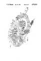
- FIG. 1is a perspective view of an oven having an air circulation and exhaust control system incorporating the present invention in which certain component parts have been omitted and certain other component parts have been broken away more clearly to illustrate certain features of the invention;
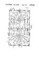
- FIG. 2is a top view of the oven of FIG. 1 in which the top panel of the oven enclosure has been omitted for clarity;
- FIG. 3is an exploded perspective view of one of the conveyor support stands of the oven of FIG. 1;
- FIG. 4is a partial side view of the oven of FIG. 1 illustrating the construction and operation of the ribbon burners;
- FIG. 5is a further illustration of the construction and operation of the ribbon burners of the oven of FIG. 1;
- FIG. 6is a transverse sectional view of the oven of FIG. 1 in which certain component parts have been omitted for clarity;
- FIG. 7is a diagramatic illustration of the construction and operation of the oven of FIG. 1;
- FIG. 8is a top view of the oven of FIG. 1;
- FIG. 9is a side view of the oven of FIG. 1 further illustrating certain components of the air circulation and exhaust control system
- FIG. 9Ais a schematic view of the control circuitry of the air circulation and exhaust control system.
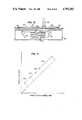
- FIG. 10is a diagramatic longitudinal sectional view of the oven of FIG. 1 illustrating the flow of exhaust gases therefrom;
- FIG. 11is a chart schematically illustrating the operation of the exhaust fans of the oven of FIG. 1;
- FIG. 12is a view similar to FIG. 2 illustrating a second embodiment of the invention.
- the oven 20includes an enclosure 24 comprising a bottom panel or floor 26, side panels or walls 28 and a ceiling or top panel 30.
- the walls 28 and the top panel 30preferably are formed of opposed sheet metal panels having a layer of thermally insulating material sandwiched therebetween.
- the floor 26may be formed from similar thermally insulated panels, or from concrete or the like.
- the floor 26, the walls 28, and the top panel 30define an oven interior 32.
- a conveyor 40is located in the oven interior 32.
- the conveyor 40is preferably constructed as illustrated and described in co-pending patent application Ser. No. 880,642, filed June 26, 1986, the disclosure of which is incorporated herein by reference.
- the conveyor 40preferably has a generally oval shape with relatively elongated sides and relatively curved ends. While the particular conveyor 40 in the oven 20 is a double spiral conveyor, it will be understood that other conveyor configurations can be used in the practice of the invention.
- the conveyor 40comprises an interior, ascending spiral 42 and an exterior, descending spiral 44.
- An inlet tier 46comprising the lowermost tier of one side of the conveyor 40 extends through an inlet door 48 of the enclosure 24.
- a first transfer portion 50connects the inlet tier 46 with the interior, ascending spiral 42.
- the interior, ascending spiral 42comprises a plurality of conveyor tiers including an uppermost tier 52.
- a second transfer portion 54connects the uppermost tier 52 of the ascending spiral 42 with an upper tier 56 of the exterior, descending spiral 44 of the conveyor 40.
- the descending spiral 44comprises a plurality of conveyor tiers, including an outlet tier 58 that forms the lowermost tier of the descending spiral 44.
- the outlet tier 58is on the opposite side of the conveyor 40 from the inlet tier 46, and extends outside the enclosure 24 through a door 60.
- inlet tier 46 and the outlet tier 58are situated in the same plane. This greatly facilitates both the construction and the operation of the oven 20.
- order of ascension and decension, the location of the transfer portions, and the location of the inlet and outlet tiersmay be varied in accordance with the requirements of particular applications of the invention.
- dough receiving trays Tare sequentially received on the inlet tier 46.
- the trays Twill be received in the oven 20 directly from a proofer wherein dough contained in the trays T has been caused to rise.
- the dough receiving trays Ttravel along the inlet tier 46 and across the first transfer portion 50 to the interior, ascending spiral 42 of the conveyor 40.
- the dough receiving trays Tare transported upwardly along each of the tiers of the ascending spiral 42 and ultimately arrive at the uppermost tier 52.
- the dough receiving trays Tmove across the second transfer portion 54 to the exterior, descending spiral 44 of the conveyor 40.
- the food receiving trays Tare thereafter transported downwardly, traveling along each of the tiers of the descending spiral 44 to arrive at the outlet tier 58 whereupon the food receiving trays T are transported out of the enclosure 24 of the oven 20.
- the conveyor 40 of the oven 20includes a continuous track 70.
- the operating components of the conveyor 40 including the track 70are supported by a plurality of support stands 72 which are preferably formed from a corrosion-resistant material such as stainless steel or "CORTEN" steel.
- Each support stand 72includes a bottom plate 74 secured to the floor 26 of the enclosure 24 by suitable fasteners extending through fastener receiving apertures 76.
- a pair of side plates 78are secured to and extend upwardly from the bottom plate 74, and a top plate 80 connects the upper ends of the side plates 78.
- a plurality of brackets 82are secured to and extend inwardly from the side plates 78 of the support stand 72.
- the brackets 82are arranged in opposed sets.
- a plate 84interconnects each set of brackets 82 by means of suitable fasteners 86 extending through fastener receiving holes 88 and 90 formed in the brackets 82 and the plate 84, respectively.
- a plurality of track supporting saddles 92are each ridgedly secured to a portion of the track extending adjacent one of the support stands 72 by welding or by suitable fasteners.
- Each saddle 92includes a plate receiving aperture 94 which receives one of the plates 84 interconnecting an opposed set of brackets 82 of the support stand 72.
- the aperture 94 of each saddle 92is designed loosely to receive its corresponding plate 84 in the horizontal direction, with the tolerance in the vertical direction being a slide fit. In this manner, the conveyor 40 of the oven 20 is securely supported within the oven interior 32 while simultaneously accommodating thermal expansion and contraction of the component parts of the conveyor 40 and the support stands 72.
- each ribbon burner 100comprises a V-shaped length of metal tubing 102 having a slot 104 formed therein from which a mixture of natural gas and air is discharged for combustion.
- the V-shaped length of metal tubing 102is supported by a three-point suspension system.
- a pair of collars 106 supported from frame members 108loosely receive the tubing 102 to facilitate thermal expansion thereof.
- a pin and slot connection 110supports the apex of the V-shaped length of metal tubing 102 from a frame member 112, again accommodating thermal expansion.
- An inlet manifold 114extends to an elbow 116.
- a length of flexible tubing 118connects the elbow 116 to the V-shaped length of metal tubing 102.
- a supply of combustion airis connected to a manifold 120 through a conduit 122 having an air flow indicator 123 mounted thereon.
- a supply of gaseous fuelfor example natural gas, butane, propane, etc., is connected to a manifold 124 through a conduit 126.
- the manifolds 120 and 124are in turn connected to mixing valves 128 that interconnect the conduits 122 and 126 and the inlet manifolds 114.
- the gaseous fuelis provided at a pressure of one atmosphere absolute. Air passing through the mixing valves 128 and the inlet manifolds 114 causes a pressure differential between the flowing air and the gaseous fuel. This pressure differential draws gaseous fuel into the mixing valves 128 and the inlet manifolds 114 thereby receive a combustible mixture from the mixing valves 128 comprising about ten parts combustion air and one part gaseous fuel as determined by the setting of the valves 128.
- the air flow indicator 123senses the air flow volume and provides the information to a computer 129.
- the combustible mixtureflows through the inlet manifolds 114, the flexible tubing 118 and the V-shaped length of metal tubing 102 and is discharged through the slot 104.
- Each ribbon burner 100is provided with an ignitor 130 situated at one end of the slot 104.
- the ignitors 130comprise spark plugs that are actuated by transformers situated within a housing 132. Upon actuation, the ignitors 130 ignite the combustible mixture discharged through the slots 104 of the V-shaped lengths of metal tubing 102.
- flame sensors 134mounted in the walls 28 of the enclosure 24.
- the flame sensors 134comprise optical devices that are focused on the ends of the slots 104 of the lengths of V-shaped metal tubing 102 remote from the ignitors 130.
- the flame sensors 134normally provide an electrical signal indicative of the presence of flame at the ends of the slots 104 remote from the inlet ends thereof.
- the air circulation and exhaust control system 22 of the oven 20includes a pair of inlet plenums 140 each having an outer inlet aperture 142 and an inner inlet aperture 144.
- the inlet plenums 140extend to a circulation fan 146 located inside the oven enclosure 24 which is driven by a motor 148 mounted on top of the top panel 30 of the enclosure 24 and, therefore, outside the oven interior 32.
- the circulation fan 146draws heated gases into the inlet plenums 140 through the inlet apertures 142 and 144 thereof and discharges the heated gases through outlet passages 150.
- the outlet passages 150extend to outlet plenums 152 which in turn extend to discharge tubes 154.
- Each discharge tube 154includes a relatively large diameter inner section 156 and a relatively small diameter outer section 158. Both the inner section 156 and the outer section 158 of the discharge tube 154 have a plurality of outlet apertures 160 formed therein.
- each discharge tubeis rotatably positionable relative to its respective outlet plenum 152 so that the direction of discharge of heated gases through the outlet apertures 160 in each inner section 156 is adjustable in accordance with the operating parameters of the particular oven installation.
- the outer section 158 of each discharge tube 154is rotatably positionable relative to the inner section 156 thereof, again to direct the discharge of heated gases therefrom as may be required by particular applications of the invention.
- the conveyor 40has a generally oval shape comprising relatively long, straight side portions and relatively curved end portions.
- the ribbon burners 100are adjacent the relatively straight side portions of the tiers of the conveyor 40. Operating the ribbon burners 100 creates heated gases comprising both the products of combustion and air which has been heated by contact with and mixture into the products of combustion. These heated gases tend to flow upwardly within the oven interior 32 and therefore flow into the inlet apertures 142 and 144 of the inlet plenums 140 of the air circulation and exhaust control system 22.
- the outlet plenums 152 of the air circulation and exhaust control system 22are semi-cylindrical.
- the discharge tubes 154extend radially outwardly from the outlet plenums 152 to points situated adjacent the relatively curved ends of the tiers of the conveyor 40.
- the air circulation and exhaust control system 22functions in one aspect to withdraw heated gases from adjacent the relatively straight side portions of the conveyor 40 and to recirculate and discharge the heated gases in regions adjacent to the curved end portions of the conveyor 40.
- FIG. 7diagramatically illustrates the path of the dough receiving trays T through the oven 20 and the relationship of the moving dough receiving trays T to the ribbon burners 100 and the discharge tubes 154.
- a ribbon burner 100underlies the inlet tier 46 of the conveyor 40.
- the first transfer portion 50 of the conveyor 40directs the trays T to the interior, ascending spiral 42.
- Ribbon burners 100underlie lower portions of the ascending spiral 42.
- Both discharge tubes 154 and ribbon burners 100underlie the upper portions of the ascending spiral 42.
- the trays THaving reached the top of the interior, ascending spiral 42, the trays T travel across the second transfer portion 54 to the exterior, descending spiral 44 of the conveyor 40. As the dough receiving trays T and the food products contained therein travel downwardly on the descending spiral 44 of the conveyor 40, the trays pass under the discharge tubes 154 and over the ribbon burners 100.
- the positioning of the discharge tubes 154 above the trays T and the products carried therein on the descending spiral 44 of the conveyor 40is an important feature of the invention.
- the doughis wet and tender. It is important to heat the dough and cause it to lose water before putting a crust on the dough.
- the discharge tubes 154are therefore placed beneath the interior, ascending spiral 42 of the conveyor 40.
- the concentration of discharge tubes 154 and ribbon burners 100is greater around the inside loop than around the outside loop to assist in driving water out of the dough and toughening the dough.
- the discharge tubes 154are above the dough receiving trays T to assist in building a crust and browning the dough products. It will be understood, however, that the direction of discharge of heated gases from the tubes 154 depends upon the nature of the food products being prepared in the oven.
- FIGS. 1 and 6the flow of the hot gases within the oven interior 32 is shown.
- the heated gases caused by operation of the ribbon burners 100flow into the inlet apertures 142 and 144 and into the inlet plenums 140 as shown by the arrows 170.
- the gasesflow out of the discharge tubes 154 as shown by the arrows 172.
- the flow from the orifices 160is shown as directed horizontally downwardly onto the exterior, descending spiral 44 and vertically upwardly toward the bottom of the interior, ascending spiral 42 of the conveyor 40.
- the orifices 160 of the relatively large diameter inner sections 156 and the relatively small diameter outer sections 158 of each of the discharge tubes 154are positioned to eliminate local "hot spots" and "cold spots” found in each individual oven made according to the present invention.
- the heated gases from the outlet apertures 160 in certain of the discharge tubes 154may be directed toward the back of the dough receiving trays to adjust for the speed of the conveyor and eliminate cold spots.
- the direction of the flow of gases through the outlet apertures 160 of the discharges tubes 154is critical to successful operation of the present invention.
- different conveyor speeds, different gas and air flow rates, different oven temperatures and different types of dough and productfor instance, fermentation dough versus continuous dough, dough sprayed with water, seeds on top of the dough, etc., all affect the baking of the product in any given oven. Therefore, the rotational positioning of the outlet apertures 160 as indicated by the arrows 172 must be individually adjusted by a skilled oven operator for each of the discharge tubes 154 in each oven and for each product produced in the oven.
- a pair of discharge ports 180are formed in the top panel 30 of the enclosure 24 of the oven 20.
- a pair of conduits 182each extend from one of the discharge ports 180 to an exhaust blower assembly 184.
- the exhaust blower assemblies 184withdraw heated gases from the oven interior 32 and discharge the heated gases into the atmosphere through stacks 186.
- each blower assembly 184includes a blower shaft 190 having a sprocket 192 secured thereto.
- a timing belt 194drivingly connects the sprocket 192 with a sprocket 196 which in turn drives a speed switch 198 and a tachometer 200.
- the tachometer 200provides the computer 129 with an electrical output analogous to the rotational speed of a blower shaft 190, and the speed switch 198 functions as a governor to prevent operation of the ribbon burners 100 until the blower assembly 184 is operating at a sufficiently high rotational speed.
- the rate of flow of combustion air into the manifold 120is continuously monitored by the air flow indicator 123 and the flow rate is provided to the computer 129.
- the flow rate of the gaseous fuelis proportional to the flow rate of the combustion air and is determined by the setting of the mixing valves 128.
- the computer 129compares the combined flow rate with the exhaust flow rate as indicated by the tachometer 200.
- the computer 129then adjusts the speed of each exhaust blower assembly 184 so that the operational speed of each exhaust blower assembly 184 is maintained at a level that results in an exhaust flow rate that is roughly 7% above the combined flow rate of the combustion air and the gaseous fuel into the oven interior 32.
- a slight negative pressureis maintained at the doors 48 and 60 through which the trays T enter and leave the oven interior 32.
- the exhaust blower assembly 184 of the air circulation and exhaust control system 22has several operational ranges. These include a standby range 202, a baking range 204, a reserve range 206 and a purge range 208.
- the standby range 202is used when the oven is in a heated condition but no food products are being transported therethrough by the conveyor 40.
- the baking range 204is the normal operational range of the exhaust blower assembly 184 when the oven 20 processes food products that are transported therethrough on the trays T by the conveyor 40.
- the reserve range 206is normally not used, but is provided for those circumstances in which the operational conditions of the oven dictate a greater exhaust flow rate than is normally required.
- the purge range 208is used to remove all heated gases from the interior of the oven, for example, during emergency conditions, or when it is necessary to prepare the oven for maintenance, etc.
- the relationship between the recirculation components and the exhaust control components of the air circulation and exhaust control system 22 of the oven 20is further illustrated by reference to FIG. 10.
- the combined flow rate of combustion air and gaseous fuel into the ribbon burners 100is 360 cubic feet per minute.
- the flow rate of heated gases through the inlet plenums 140, the outlet passages 150, the outlet plenums 152, and the discharge tubes 154 under the action of the circulation fan 146 as indicated by the arrows 210is 2400 cubic feet per minute.
- the flow rate of gases out of the oven through the discharge ports 180 as indicated by the arrows 212is 390 cubic feet per minute.
- the rate of flow of gases returned to the burner area as indicated by the arrows 214is 2010 cubic feet per minute.
- the flow rate of air through the doors 48 and 60, which also flows to the burner areais 30 cubic feet per minute.
- the combined flow rate of combustion air and gaseous fuel into the ribbon burners 100is 600 cubic feet per minute.
- the recirculation rate as indicated by the arrows 210is 2400 cubic feet per minute
- the exhaust flow rate as indicated by the arrows 212is 640 cubic feet per minute
- the rate of return of gases to the burner area as indicated by the arrows 214is 1760 cubic feet per minute.
- the rate of flow of air through the doors 48 and 60is 40 cubic feet per minute.
- the combined flow rate of combustion air and gaseous fuel into the ribbon burners 100is 920 cubic feet per minute
- the recirculation rate as indicated by the arrows 210is 2400 cubic feet per minute
- the exhaust flow rate as indicated by the arrows 212is 990 cubic feet per minute
- the rate of flow of gases back to the burner area as indicated by the arrows 214is 1410 cubic feet per minute.
- the rate of flow of air through the doors 48 and 60is 70 cubic feet per minute.
- the combined flow rate of combustion air and gaseous fuel into the ribbon burners 100is 1065 cubic feet per minute
- the recirculation rate as indicated by the arrows 210is 2400 cubic feet per minute
- the exhaust flow rate as indicated by the arrows 212is 1140 cubic feet per minute.
- gasesare returned to the burner area as indicated by the arrows 214 at the rate of 1260 cubic feet per minute, and the rate of air flow through the doors 48 and 60 is 75 cubic feet per minute.
- the ribbon burners 100are not operated and neither combustion air nor gaseous fuel is admitted thereto.
- the recirculation rate as indicated by the arrows 210is 2400 cubic feet per minute
- the exhaust flow rate as indicated by the arrows 212is 3800 cubic feet per minute.
- heated gasesare withdrawn from the burner area in the direction opposite that indicated by the arrows 214 at a rate of 1400 cubic feet per minute.
- the rate of air flow into the oven interioris 3800 cubic feet per minute.
- an oven 220comprising a second embodiment of the invention is illustrated therein.
- the oven 220incorporates numerous component parts which are substantially identical in function and construction to component parts of the oven 20 as illustrated in FIGS. 1-11 and described above. Such identical component parts are designated in FIG. 12 with the same reference numerals utilized to designate the component parts of the oven 20, but are differentiated therefrom by means of a prime (') designation.
- the oven 220differs from the oven 20 comprising the first embodiment of the invention primarily in the fact that it incorporates dual inlet plenums 222 and 224 and dual circulation fans 226 and 228 leading to the outlet passages 150', the outlet plenums 152' and the discharge tubes 154'. This allows control of the circulation rate of heated gases to the opposite ends of the oven interior 32' by regulating the operational speeds of the circulation fans 226 and 228 rather than the use of dampers as might otherwise be required in those embodiments of the invention employing a single circulation fan.
Landscapes
- Life Sciences & Earth Sciences (AREA)
- Engineering & Computer Science (AREA)
- Food Science & Technology (AREA)
- Baking, Grill, Roasting (AREA)
Abstract
Description
Claims (17)
Priority Applications (1)
| Application Number | Priority Date | Filing Date | Title |
|---|---|---|---|
| US07/101,840US4792303A (en) | 1986-12-01 | 1987-09-28 | Air circulation and exhaust control system for commercial ovens |
Applications Claiming Priority (2)
| Application Number | Priority Date | Filing Date | Title |
|---|---|---|---|
| US06/936,160US4726766A (en) | 1986-12-01 | 1986-12-01 | Air circulation and exhaust control system for commerical ovens |
| US07/101,840US4792303A (en) | 1986-12-01 | 1987-09-28 | Air circulation and exhaust control system for commercial ovens |
Related Parent Applications (1)
| Application Number | Title | Priority Date | Filing Date |
|---|---|---|---|
| US06/936,160DivisionUS4726766A (en) | 1986-12-01 | 1986-12-01 | Air circulation and exhaust control system for commerical ovens |
Publications (1)
| Publication Number | Publication Date |
|---|---|
| US4792303Atrue US4792303A (en) | 1988-12-20 |
Family
ID=25468253
Family Applications (3)
| Application Number | Title | Priority Date | Filing Date |
|---|---|---|---|
| US06/936,160Expired - Fee RelatedUS4726766A (en) | 1986-12-01 | 1986-12-01 | Air circulation and exhaust control system for commerical ovens |
| US07/101,840Expired - Fee RelatedUS4792303A (en) | 1986-12-01 | 1987-09-28 | Air circulation and exhaust control system for commercial ovens |
| US07/101,841Expired - Fee RelatedUS4787842A (en) | 1986-12-01 | 1987-09-28 | Air circulation and exhaust control system for commercial ovens |
Family Applications Before (1)
| Application Number | Title | Priority Date | Filing Date |
|---|---|---|---|
| US06/936,160Expired - Fee RelatedUS4726766A (en) | 1986-12-01 | 1986-12-01 | Air circulation and exhaust control system for commerical ovens |
Family Applications After (1)
| Application Number | Title | Priority Date | Filing Date |
|---|---|---|---|
| US07/101,841Expired - Fee RelatedUS4787842A (en) | 1986-12-01 | 1987-09-28 | Air circulation and exhaust control system for commercial ovens |
Country Status (1)
| Country | Link |
|---|---|
| US (3) | US4726766A (en) |
Cited By (21)
| Publication number | Priority date | Publication date | Assignee | Title |
|---|---|---|---|---|
| US4941819A (en)* | 1986-12-01 | 1990-07-17 | Stewart Systems, Inc. | Air circulation and exhaust control system for commercial ovens |
| US4997365A (en)* | 1990-01-23 | 1991-03-05 | Apv Baker Inc. | Spiral conveyor baking apparatus |
| US5010808A (en)* | 1990-01-23 | 1991-04-30 | Apv Baker Inc. | Spiral conveyor oven |
| WO1991011660A1 (en)* | 1990-01-26 | 1991-08-08 | Stein, Inc. | Cooking oven for slow cooking of food products |
| US5111929A (en)* | 1991-04-24 | 1992-05-12 | Checker Machine, Inc. | Spiral conveyor cleaning system |
| US5123336A (en)* | 1988-11-28 | 1992-06-23 | Koenig Helmut | Plant for treating baking good |
| US5243962A (en)* | 1990-01-26 | 1993-09-14 | Stein, Inc. | Cooking oven for slow-cooking of food products |
| US5329916A (en)* | 1992-02-26 | 1994-07-19 | Koppens Machinefabriek B.V. | Oven |
| US5335590A (en)* | 1992-10-30 | 1994-08-09 | Philip Morris Incorporated | Apparatus for treatment of solid material |
| US5702245A (en)* | 1996-03-20 | 1997-12-30 | Stein, Inc. | Conveyor for processing equipment having gas flow compensation |
| US6095805A (en)* | 1997-04-11 | 2000-08-01 | Koppens Convenience Food Systems | Steam oven |
| US6418834B1 (en)* | 1999-07-26 | 2002-07-16 | Paul M. Perrine | Apparatus for treating an item during travel of the item along a treating trough |
| US20070012307A1 (en)* | 2004-03-23 | 2007-01-18 | Middleby Corporation | Conveyor oven apparatus and method |
| US20070298148A1 (en)* | 2004-11-08 | 2007-12-27 | Stork Titan B.V. | Treatment Device and Method for Treating Food Products With Conditioned Air |
| US20100112169A1 (en)* | 2008-10-24 | 2010-05-06 | Gunawardena Ramesh M | Continuous process for cooking bacon with improved recovery |
| US20110048244A1 (en)* | 2009-08-28 | 2011-03-03 | Wiker John H | Apparatus and method for controlling a combustion blower in a gas-fueled conveyor oven |
| US20110048245A1 (en)* | 2009-08-28 | 2011-03-03 | Schjerven Sr William S | Apparatus and method for controlling a conveyor oven |
| USRE43035E1 (en) | 2000-11-17 | 2011-12-20 | Middeby Marshall Incorporated | Conveyor oven having an energy management system for a modulated gas flow |
| US20160000095A1 (en)* | 2012-01-27 | 2016-01-07 | Ts Techniek Bv | Dual drum spiral oven |
| US9585400B2 (en) | 2004-03-23 | 2017-03-07 | The Middleby Corporation | Conveyor oven apparatus and method |
| US10024548B2 (en) | 2003-02-21 | 2018-07-17 | The Middleby Corporation | Self-cleaning oven |
Families Citing this family (35)
| Publication number | Priority date | Publication date | Assignee | Title |
|---|---|---|---|---|
| US4726766A (en)* | 1986-12-01 | 1988-02-23 | Stewart Systems, Inc. | Air circulation and exhaust control system for commerical ovens |
| US4882981A (en)* | 1987-12-02 | 1989-11-28 | Stewart Systems, Inc. | Continuous proof and bake apparatus having improved conveyor system |
| US4912943A (en)* | 1988-12-14 | 1990-04-03 | Liquid Air Corporation | Method and apparatus for enhancing production capacity and flexibility of a multi-tier refrigeration tunnel |
| US5322007A (en)* | 1991-08-15 | 1994-06-21 | Heat And Control, Inc. | Compact, high-capacity oven |
| CA2130961C (en)* | 1993-12-01 | 2004-01-20 | Henry Jack Moore Jr. | Induced draft combustion water heater |
| NL9401778A (en)* | 1994-10-26 | 1996-06-03 | Kaak Johan H B | Cupboard for temporarily storing dough pieces. |
| US5606861A (en)* | 1995-06-07 | 1997-03-04 | Air Liquide America Corporation | Crossflow cryogenic freezer and method of use |
| ES2120342B1 (en)* | 1995-10-31 | 1999-06-01 | Puig Martinez Eulalia | INSTALLATION FOR THE PREPARATION OF PORTIONS OF BREAD MASS. |
| US5921091A (en)* | 1996-10-09 | 1999-07-13 | American Air Liquide, Incorporated | Liquid air food freezer and method |
| US5765381A (en)* | 1997-03-04 | 1998-06-16 | Air Liquide America Corporation | Multitier crossflow cryogenic freezer and method of use |
| US6125192A (en)* | 1997-04-21 | 2000-09-26 | Digital Persona, Inc. | Fingerprint recognition system |
| US5881636A (en)* | 1998-07-01 | 1999-03-16 | Sweet; Dan | Heat impingement bake oven |
| US6065463A (en)* | 1998-10-19 | 2000-05-23 | Sasib Bakery North America, Inc. | Forced convective track oven |
| US6138660A (en)* | 1999-01-06 | 2000-10-31 | Sasib Bakery North America, Inc. | Forced convective track oven having oval spirals |
| US6408842B1 (en)* | 2000-03-29 | 2002-06-25 | Alfred Herrera | Oven |
| DE10038169A1 (en)* | 2000-08-04 | 2002-03-07 | November Ag Molekulare Medizin | Synthetic particle for marking a substance |
| US6689407B2 (en)* | 2001-06-25 | 2004-02-10 | Goodmark Foods, Inc. | Enhanced capacity food processing systems with efficient space utilization |
| US6793068B2 (en)* | 2002-02-04 | 2004-09-21 | Conagra Foods, Inc. | Food transport routing systems, devices, and guides for food processing systems and related methods |
| US20030159653A1 (en)* | 2002-02-28 | 2003-08-28 | Dando Ross S. | Manifold assembly for feeding reactive precursors to substrate processing chambers |
| US6713107B2 (en)* | 2002-03-01 | 2004-03-30 | Conagra Foods, Inc. | Airflow distribution systems for food processors |
| CA2497378A1 (en)* | 2005-02-16 | 2006-08-16 | Alberta Welltest Incinerators Ltd. | Gas phase thermal unit |
| NL1032727C2 (en)* | 2006-10-23 | 2008-04-24 | Kaak Johan H B | Oven with several horizontal flow chambers. |
| US10398148B2 (en) | 2008-01-03 | 2019-09-03 | Souhel Khanania | Oven |
| US8201493B2 (en)* | 2008-01-03 | 2012-06-19 | Souhel Khanania | Oven |
| US8167114B2 (en)* | 2008-01-03 | 2012-05-01 | Souhel Khanania | System and method for product removal |
| ES2879632T3 (en)* | 2008-06-19 | 2021-11-22 | Gea Food Solutions Bakel Bv | Spiral oven with controlled air flow along the width of the belt |
| US8646383B1 (en)* | 2009-09-15 | 2014-02-11 | David Howard | Spiral oven apparatus and method of cooking |
| US9375016B2 (en)* | 2012-07-31 | 2016-06-28 | Stewart Systems Baking, LLC | Convection heating in track ovens |
| US8652556B1 (en)* | 2012-09-27 | 2014-02-18 | Laitram, L.L.C. | Cooking method and cooker for cooking foodstuffs in stackable trays |
| KR102305832B1 (en)* | 2015-01-05 | 2021-09-28 | 삼성전자주식회사 | Gas Oven |
| US10039304B2 (en) | 2015-05-06 | 2018-08-07 | John Bean Technologies Ab | System and method for adjusting air flow in spiral conveyers |
| ES2784700T3 (en)* | 2015-11-17 | 2020-09-30 | Gea Food Solutions Bakel Bv | Improved drag oven |
| ES2702554T3 (en)* | 2016-04-26 | 2019-03-01 | Metalquimia Sa | Plant and air drying method of chopped food |
| WO2019224459A2 (en)* | 2018-05-24 | 2019-11-28 | Sg2C | Installation for product flow regulation |
| CN109588435A (en)* | 2018-12-21 | 2019-04-09 | 广州复雅机械设备有限公司 | Food transmitting device |
Citations (45)
| Publication number | Priority date | Publication date | Assignee | Title |
|---|---|---|---|---|
| US798345A (en)* | 1904-10-10 | 1905-08-29 | Frank Johnson | Drying apparatus. |
| US937000A (en)* | 1905-01-27 | 1909-10-12 | Sydney Jacobson | Continuous baking-oven. |
| US1073126A (en)* | 1912-01-23 | 1913-09-16 | Minor L Hitchcock | Baking device. |
| US1555336A (en)* | 1923-07-14 | 1925-09-29 | Westinghouse Electric & Mfg Co | Automatic bread toaster |
| US1716460A (en)* | 1926-04-08 | 1929-06-11 | Baker Perkins Co Inc | Bread-making plant and machinery |
| US1790876A (en)* | 1931-02-03 | mueller | ||
| US1938294A (en)* | 1931-03-18 | 1933-12-05 | Edward J Lauterbur | Proofing and baking apparatus |
| US1949684A (en)* | 1932-01-14 | 1934-03-06 | Louis D Houlis | Sectional baking oven |
| US2236085A (en)* | 1940-07-22 | 1941-03-25 | Petersen Oven Co | Baking oven |
| US2236711A (en)* | 1938-07-05 | 1941-04-01 | John W Billingsley | Dehydrator |
| US2271091A (en)* | 1940-06-22 | 1942-01-27 | Mach And Tool Designing Co | Method and apparatus for heat treating and sintering |
| US2289629A (en)* | 1941-01-21 | 1942-07-14 | Petersen Oven Co | Oven construction |
| US2373076A (en)* | 1940-02-05 | 1945-04-03 | Baker Perkins Inc | Oven mechanism |
| GB621799A (en)* | 1946-05-24 | 1949-04-20 | John Edward Pointon | Improvements in and relating to ovens for baking bread or the like |
| US2674809A (en)* | 1950-08-24 | 1954-04-13 | Raduner & Co Ag | Apparatus for thermic treatment by infrared radiation |
| US2709412A (en)* | 1950-02-25 | 1955-05-31 | Eagerman Julius | Automatic baking oven |
| US2732627A (en)* | 1956-01-31 | Drying apparatus for alimentary paste of | ||
| US2780182A (en)* | 1952-10-16 | 1957-02-05 | American Mach & Foundry | Automatic bread plant |
| US2961976A (en)* | 1956-03-30 | 1960-11-29 | Ooms Hugo Theodore Guillaume | Arrangement for the distribution and regulation of the heating fluid in baker's ovens and the like |
| US3027994A (en)* | 1962-04-03 | Bread and roll cooler | ||
| US3240316A (en)* | 1966-03-15 | Bread cqqling apparatus | ||
| US3249741A (en)* | 1963-05-20 | 1966-05-03 | Reflectotherm Inc | Apparatus for baking by differential wave lengths |
| US3269142A (en)* | 1964-12-24 | 1966-08-30 | Frick Co | Processing apparatus for changing the temperature of articles |
| US3310007A (en)* | 1964-01-14 | 1967-03-21 | John C Ford | Tortilla oven |
| US3440973A (en)* | 1966-11-10 | 1969-04-29 | William E Lanham | Proofers for bread products and conveyor systems which are adapted to use therein |
| US3478705A (en)* | 1967-04-03 | 1969-11-18 | William E Lanham | Proofers and ovens for bread products |
| US3570651A (en)* | 1966-11-10 | 1971-03-16 | William E Lanham | Conveyor system |
| US3581679A (en)* | 1968-12-02 | 1971-06-01 | Winkler Kg F | Oven apparatus |
| US3589307A (en)* | 1968-11-06 | 1971-06-29 | Lanham Machinery Co Inc | Oven |
| US3861334A (en)* | 1974-04-05 | 1975-01-21 | Air Preheater | Waste heat recovery |
| US4098200A (en)* | 1976-12-09 | 1978-07-04 | Dauvergne Hector A | Low pollution solid waste burner |
| US4230451A (en)* | 1978-02-17 | 1980-10-28 | Maurice Chambe | Apparatus for the thermal treatment of organic materials |
| US4244349A (en)* | 1978-12-22 | 1981-01-13 | Scheu Manufacturing Company | Portable forced air heater |
| US4270467A (en)* | 1980-01-14 | 1981-06-02 | Enertherm, Inc. | Low mass flow waste fuel incinerator |
| US4309171A (en)* | 1980-05-27 | 1982-01-05 | Granco Equipment, Inc. | Billet heating furnace with pressurized entrance seal |
| US4355601A (en)* | 1981-09-25 | 1982-10-26 | Conoco Inc. | Recirculating flue gas fluidized bed heater |
| US4449921A (en)* | 1982-09-02 | 1984-05-22 | Frank Catallo | Combined oven and fume incinerator and method of operating same |
| US4507083A (en)* | 1982-09-21 | 1985-03-26 | Joseph Fraioli | Gas-fired infrared projection heater |
| US4544352A (en)* | 1983-12-09 | 1985-10-01 | Lanham Machinery Company, Inc. | Baking oven with heated air distribution |
| US4565137A (en)* | 1983-08-08 | 1986-01-21 | Aqua-Chem, Inc. | Bio-mass suspension burner |
| US4573907A (en)* | 1984-11-07 | 1986-03-04 | Maxon Corporation | Low oxygen and low pressure drop burner |
| US4608961A (en)* | 1984-04-30 | 1986-09-02 | Lanham Machinery Company, Inc. | Exhaust damper control |
| US4631029A (en)* | 1983-12-09 | 1986-12-23 | Lanham Machinery Company, Inc. | Baking oven with heated air distribution-II |
| US4726766A (en)* | 1986-12-01 | 1988-02-23 | Stewart Systems, Inc. | Air circulation and exhaust control system for commerical ovens |
| US4891517A (en)* | 1987-07-22 | 1990-01-02 | Fuji Photo Film Co., Ltd. | Heat sensitive copying machine |
Family Cites Families (12)
| Publication number | Priority date | Publication date | Assignee | Title |
|---|---|---|---|---|
| US1707281A (en)* | 1925-10-30 | 1929-04-02 | Drying Systems Inc | Draft control for furnaces |
| US2160968A (en)* | 1936-08-12 | 1939-06-06 | B F Sturtevant Co | Fan system |
| US2202793A (en)* | 1939-04-06 | 1940-05-28 | B F Sturtevant Co | Fan system |
| US2348950A (en)* | 1941-09-30 | 1944-05-16 | Clayton G Anderson | Draft control means for furnaces |
| US3587490A (en)* | 1969-08-15 | 1971-06-28 | Combustion Eng | Method and means for inducing draft in a stack |
| US4204832A (en)* | 1978-08-10 | 1980-05-27 | Modine Manufacturing Company | Gas burner device |
| US4262608A (en)* | 1979-06-14 | 1981-04-21 | Jackson Bert W | Method and apparatus for powered flue products exhaust and preheated combustion air supply |
| US4402303A (en)* | 1982-01-28 | 1983-09-06 | Koenneman Donald E | Fan flow control device |
| US4483258A (en)* | 1982-07-08 | 1984-11-20 | Clear Air, Inc. | Incinerator steam generation system |
| US4487137A (en)* | 1983-01-21 | 1984-12-11 | Horvat George T | Auxiliary exhaust system |
| US4591517A (en)* | 1984-06-08 | 1986-05-27 | Overly, Inc. | Web dryer with variable ventilation rate |
| AT385524B (en)* | 1985-03-18 | 1988-04-11 | Fehrer Textilmasch | DEVICE FOR PRODUCING A YARN |
- 1986
- 1986-12-01USUS06/936,160patent/US4726766A/ennot_activeExpired - Fee Related
- 1987
- 1987-09-28USUS07/101,840patent/US4792303A/ennot_activeExpired - Fee Related
- 1987-09-28USUS07/101,841patent/US4787842A/ennot_activeExpired - Fee Related
Patent Citations (46)
| Publication number | Priority date | Publication date | Assignee | Title |
|---|---|---|---|---|
| US3240316A (en)* | 1966-03-15 | Bread cqqling apparatus | ||
| US1790876A (en)* | 1931-02-03 | mueller | ||
| US2732627A (en)* | 1956-01-31 | Drying apparatus for alimentary paste of | ||
| US3027994A (en)* | 1962-04-03 | Bread and roll cooler | ||
| US798345A (en)* | 1904-10-10 | 1905-08-29 | Frank Johnson | Drying apparatus. |
| US937000A (en)* | 1905-01-27 | 1909-10-12 | Sydney Jacobson | Continuous baking-oven. |
| US1073126A (en)* | 1912-01-23 | 1913-09-16 | Minor L Hitchcock | Baking device. |
| US1555336A (en)* | 1923-07-14 | 1925-09-29 | Westinghouse Electric & Mfg Co | Automatic bread toaster |
| US1716460A (en)* | 1926-04-08 | 1929-06-11 | Baker Perkins Co Inc | Bread-making plant and machinery |
| US1938294A (en)* | 1931-03-18 | 1933-12-05 | Edward J Lauterbur | Proofing and baking apparatus |
| US1949684A (en)* | 1932-01-14 | 1934-03-06 | Louis D Houlis | Sectional baking oven |
| US2236711A (en)* | 1938-07-05 | 1941-04-01 | John W Billingsley | Dehydrator |
| US2373076A (en)* | 1940-02-05 | 1945-04-03 | Baker Perkins Inc | Oven mechanism |
| US2271091A (en)* | 1940-06-22 | 1942-01-27 | Mach And Tool Designing Co | Method and apparatus for heat treating and sintering |
| US2236085A (en)* | 1940-07-22 | 1941-03-25 | Petersen Oven Co | Baking oven |
| US2289629A (en)* | 1941-01-21 | 1942-07-14 | Petersen Oven Co | Oven construction |
| GB621799A (en)* | 1946-05-24 | 1949-04-20 | John Edward Pointon | Improvements in and relating to ovens for baking bread or the like |
| US2709412A (en)* | 1950-02-25 | 1955-05-31 | Eagerman Julius | Automatic baking oven |
| US2674809A (en)* | 1950-08-24 | 1954-04-13 | Raduner & Co Ag | Apparatus for thermic treatment by infrared radiation |
| US2780182A (en)* | 1952-10-16 | 1957-02-05 | American Mach & Foundry | Automatic bread plant |
| US2961976A (en)* | 1956-03-30 | 1960-11-29 | Ooms Hugo Theodore Guillaume | Arrangement for the distribution and regulation of the heating fluid in baker's ovens and the like |
| US3249741A (en)* | 1963-05-20 | 1966-05-03 | Reflectotherm Inc | Apparatus for baking by differential wave lengths |
| US3310007A (en)* | 1964-01-14 | 1967-03-21 | John C Ford | Tortilla oven |
| US3269142A (en)* | 1964-12-24 | 1966-08-30 | Frick Co | Processing apparatus for changing the temperature of articles |
| US3440973B1 (en)* | 1966-11-10 | 1987-01-06 | ||
| US3570651A (en)* | 1966-11-10 | 1971-03-16 | William E Lanham | Conveyor system |
| US3440973A (en)* | 1966-11-10 | 1969-04-29 | William E Lanham | Proofers for bread products and conveyor systems which are adapted to use therein |
| US3478705A (en)* | 1967-04-03 | 1969-11-18 | William E Lanham | Proofers and ovens for bread products |
| US3589307A (en)* | 1968-11-06 | 1971-06-29 | Lanham Machinery Co Inc | Oven |
| US3581679A (en)* | 1968-12-02 | 1971-06-01 | Winkler Kg F | Oven apparatus |
| US3861334A (en)* | 1974-04-05 | 1975-01-21 | Air Preheater | Waste heat recovery |
| US4098200A (en)* | 1976-12-09 | 1978-07-04 | Dauvergne Hector A | Low pollution solid waste burner |
| US4230451A (en)* | 1978-02-17 | 1980-10-28 | Maurice Chambe | Apparatus for the thermal treatment of organic materials |
| US4244349A (en)* | 1978-12-22 | 1981-01-13 | Scheu Manufacturing Company | Portable forced air heater |
| US4270467A (en)* | 1980-01-14 | 1981-06-02 | Enertherm, Inc. | Low mass flow waste fuel incinerator |
| US4309171A (en)* | 1980-05-27 | 1982-01-05 | Granco Equipment, Inc. | Billet heating furnace with pressurized entrance seal |
| US4355601A (en)* | 1981-09-25 | 1982-10-26 | Conoco Inc. | Recirculating flue gas fluidized bed heater |
| US4449921A (en)* | 1982-09-02 | 1984-05-22 | Frank Catallo | Combined oven and fume incinerator and method of operating same |
| US4507083A (en)* | 1982-09-21 | 1985-03-26 | Joseph Fraioli | Gas-fired infrared projection heater |
| US4565137A (en)* | 1983-08-08 | 1986-01-21 | Aqua-Chem, Inc. | Bio-mass suspension burner |
| US4544352A (en)* | 1983-12-09 | 1985-10-01 | Lanham Machinery Company, Inc. | Baking oven with heated air distribution |
| US4631029A (en)* | 1983-12-09 | 1986-12-23 | Lanham Machinery Company, Inc. | Baking oven with heated air distribution-II |
| US4608961A (en)* | 1984-04-30 | 1986-09-02 | Lanham Machinery Company, Inc. | Exhaust damper control |
| US4573907A (en)* | 1984-11-07 | 1986-03-04 | Maxon Corporation | Low oxygen and low pressure drop burner |
| US4726766A (en)* | 1986-12-01 | 1988-02-23 | Stewart Systems, Inc. | Air circulation and exhaust control system for commerical ovens |
| US4891517A (en)* | 1987-07-22 | 1990-01-02 | Fuji Photo Film Co., Ltd. | Heat sensitive copying machine |
Cited By (37)
| Publication number | Priority date | Publication date | Assignee | Title |
|---|---|---|---|---|
| US4941819A (en)* | 1986-12-01 | 1990-07-17 | Stewart Systems, Inc. | Air circulation and exhaust control system for commercial ovens |
| US5123336A (en)* | 1988-11-28 | 1992-06-23 | Koenig Helmut | Plant for treating baking good |
| US4997365A (en)* | 1990-01-23 | 1991-03-05 | Apv Baker Inc. | Spiral conveyor baking apparatus |
| US5010808A (en)* | 1990-01-23 | 1991-04-30 | Apv Baker Inc. | Spiral conveyor oven |
| WO1991011660A1 (en)* | 1990-01-26 | 1991-08-08 | Stein, Inc. | Cooking oven for slow cooking of food products |
| US5078120A (en)* | 1990-01-26 | 1992-01-07 | Stein, Inc. | Cooking oven for slow cooking of food products |
| US5243962A (en)* | 1990-01-26 | 1993-09-14 | Stein, Inc. | Cooking oven for slow-cooking of food products |
| US5111929A (en)* | 1991-04-24 | 1992-05-12 | Checker Machine, Inc. | Spiral conveyor cleaning system |
| US5329916A (en)* | 1992-02-26 | 1994-07-19 | Koppens Machinefabriek B.V. | Oven |
| US5335590A (en)* | 1992-10-30 | 1994-08-09 | Philip Morris Incorporated | Apparatus for treatment of solid material |
| US5515775A (en)* | 1992-10-30 | 1996-05-14 | Philip Morris Incorporated | Apparatus for treatment of solid material |
| US5702245A (en)* | 1996-03-20 | 1997-12-30 | Stein, Inc. | Conveyor for processing equipment having gas flow compensation |
| US6095805A (en)* | 1997-04-11 | 2000-08-01 | Koppens Convenience Food Systems | Steam oven |
| US6418834B1 (en)* | 1999-07-26 | 2002-07-16 | Paul M. Perrine | Apparatus for treating an item during travel of the item along a treating trough |
| USRE43035E1 (en) | 2000-11-17 | 2011-12-20 | Middeby Marshall Incorporated | Conveyor oven having an energy management system for a modulated gas flow |
| US10024548B2 (en) | 2003-02-21 | 2018-07-17 | The Middleby Corporation | Self-cleaning oven |
| US10036558B2 (en) | 2003-02-21 | 2018-07-31 | The Middleby Corporation | Self-cleaning oven |
| US20070012307A1 (en)* | 2004-03-23 | 2007-01-18 | Middleby Corporation | Conveyor oven apparatus and method |
| US9585400B2 (en) | 2004-03-23 | 2017-03-07 | The Middleby Corporation | Conveyor oven apparatus and method |
| US10842156B2 (en) | 2004-03-23 | 2020-11-24 | The Middleby Corporation | Conveyor oven apparatus and method |
| US20090075224A1 (en)* | 2004-03-23 | 2009-03-19 | Wiker John H | Conveyor oven apparatus and method |
| US8087407B2 (en) | 2004-03-23 | 2012-01-03 | Middleby Corporation | Conveyor oven apparatus and method |
| US8281779B2 (en) | 2004-03-23 | 2012-10-09 | Middleby Corporation | Conveyor oven apparatus and method |
| US8371285B2 (en) | 2004-03-23 | 2013-02-12 | Middleby Corporation | Conveyor oven apparatus and method |
| US9585401B2 (en) | 2004-03-23 | 2017-03-07 | The Middleby Corporation | Conveyor oven apparatus and method |
| US8839779B2 (en) | 2004-03-23 | 2014-09-23 | Middleby Corporation | Conveyor oven apparatus and method |
| US10039289B2 (en) | 2004-03-23 | 2018-08-07 | The Middleby Corporation | Conveyor oven apparatus and method |
| US20070298148A1 (en)* | 2004-11-08 | 2007-12-27 | Stork Titan B.V. | Treatment Device and Method for Treating Food Products With Conditioned Air |
| US9700059B2 (en)* | 2004-11-08 | 2017-07-11 | Stork Titan B V | Treatment device and method for treating food products with conditioned air |
| US20100112169A1 (en)* | 2008-10-24 | 2010-05-06 | Gunawardena Ramesh M | Continuous process for cooking bacon with improved recovery |
| US8753703B2 (en) | 2008-10-24 | 2014-06-17 | John Bean Technologies Corporation | Continuous process for cooking bacon with improved recovery |
| US20110048244A1 (en)* | 2009-08-28 | 2011-03-03 | Wiker John H | Apparatus and method for controlling a combustion blower in a gas-fueled conveyor oven |
| US9609981B2 (en) | 2009-08-28 | 2017-04-04 | The Middleby Corporation | Apparatus and method for controlling a conveyor oven |
| US8839714B2 (en) | 2009-08-28 | 2014-09-23 | The Middleby Corporation | Apparatus and method for controlling a conveyor oven |
| US10362898B2 (en) | 2009-08-28 | 2019-07-30 | The Middleby Corporation | Apparatus and method for controlling a conveyor oven |
| US20110048245A1 (en)* | 2009-08-28 | 2011-03-03 | Schjerven Sr William S | Apparatus and method for controlling a conveyor oven |
| US20160000095A1 (en)* | 2012-01-27 | 2016-01-07 | Ts Techniek Bv | Dual drum spiral oven |
Also Published As
| Publication number | Publication date |
|---|---|
| US4787842A (en) | 1988-11-29 |
| US4726766A (en) | 1988-02-23 |
Similar Documents
| Publication | Publication Date | Title |
|---|---|---|
| US4792303A (en) | Air circulation and exhaust control system for commercial ovens | |
| US4941819A (en) | Air circulation and exhaust control system for commercial ovens | |
| US5906485A (en) | Tunnel-type conveyor oven having two types of heat sources | |
| US4884552A (en) | Gas oven | |
| US6880544B2 (en) | Rack oven | |
| AU2023203343B2 (en) | Convection conveyor oven manifold and damper system | |
| JPH0563719B2 (en) | ||
| US6837234B2 (en) | Oven heat exchanger and floor construction | |
| EP0274902A3 (en) | Air flow system for a low profile impingement oven | |
| US10792701B2 (en) | Pipe coupling thermal cleaning and coating curing oven and method | |
| JPH11502708A (en) | Furnace improvements | |
| US5560952A (en) | Process for continuously cooking food | |
| EP2162006B1 (en) | Gas-fired tunnel oven | |
| US5165889A (en) | Gas convection oven with heat exchanger and baffles | |
| US3494305A (en) | Heating apparatus for cooking food | |
| US4786247A (en) | Method of lengthening the flame from a gas burner | |
| US4615895A (en) | Forced air/gas burner and baking oven incorporating same | |
| US20030066204A1 (en) | Heat generating conveyor and tunnel oven | |
| GB2045593A (en) | Bakers oven | |
| WO2005094647A1 (en) | Conveyor oven apparatus and method | |
| USRE39828E1 (en) | Convection/impingement oven for continuously cooking food | |
| USRE33374E (en) | Forced air/gas burner and baking oven incorporating same | |
| US11585601B2 (en) | Flameless impingement oven | |
| JPH0821607A (en) | Gas-firing apparatus | |
| JPH08303724A (en) | Gas calcination device |
Legal Events
| Date | Code | Title | Description |
|---|---|---|---|
| AS | Assignment | Owner name:NCNB TEXAS NATIONAL BANK, A NATIONAL BANKING ASSOC Free format text:ASSIGNMENT OF ASSIGNORS INTEREST.;ASSIGNOR:NCNB TEXAS NATIONAL BANK;REEL/FRAME:005069/0538 Effective date:19890208 Owner name:FIRST CITY NATIONAL BANK OF HOUSTON, A NATIONAL BA Free format text:ASSIGNMENT OF ASSIGNORS INTEREST.;ASSIGNOR:NCNB TEXAS NATIONAL BANK;REEL/FRAME:005069/0538 Effective date:19890208 Owner name:FIRST CITY NATIONAL BANK OF HOUSTON, TEXAS Free format text:SECURITY INTEREST;ASSIGNOR:STEWART SYSTEMS, INC.;REEL/FRAME:005069/0511 Effective date:19890208 | |
| AS | Assignment | Owner name:STEWART SYSTEMS, INC. Free format text:RELEASED BY SECURED PARTY;ASSIGNOR:FIRST CITY, TEXAS-HOUSTON, N.A., FKA FIRST CITY NATIONAL BANK OF HOUSTON;REEL/FRAME:005521/0421 Effective date:19900515 Owner name:STEWART SYSTEMS, INC. Free format text:RELEASED BY SECURED PARTY;ASSIGNOR:FIRST CITY, TEXAS-HOUSTON, N.A. FKA FIRST CITY NATIONAL BANK OF HOUSTON;REEL/FRAME:005521/0393 Effective date:19900515 | |
| FEPP | Fee payment procedure | Free format text:PAYOR NUMBER ASSIGNED (ORIGINAL EVENT CODE: ASPN); ENTITY STATUS OF PATENT OWNER: LARGE ENTITY | |
| AS | Assignment | Owner name:STEWART SYSTEMS, INC., A CORP. OF DE Free format text:MERGER;ASSIGNORS:STEWART SYSTEMS, INC., A CORP. OF TX (MERGED INTO);SASIB BAKERY EQUIPMENT, INC., A DE CORP. (CHANGED INTO);REEL/FRAME:006011/0042 Effective date:19901218 | |
| FPAY | Fee payment | Year of fee payment:4 | |
| FEPP | Fee payment procedure | Free format text:PAT HLDR NO LONGER CLAIMS SMALL ENT STAT AS INDIV INVENTOR (ORIGINAL EVENT CODE: LSM1); ENTITY STATUS OF PATENT OWNER: LARGE ENTITY | |
| FPAY | Fee payment | Year of fee payment:8 | |
| FEPP | Fee payment procedure | Free format text:PAYER NUMBER DE-ASSIGNED (ORIGINAL EVENT CODE: RMPN); ENTITY STATUS OF PATENT OWNER: LARGE ENTITY Free format text:PAYOR NUMBER ASSIGNED (ORIGINAL EVENT CODE: ASPN); ENTITY STATUS OF PATENT OWNER: LARGE ENTITY | |
| REMI | Maintenance fee reminder mailed | ||
| LAPS | Lapse for failure to pay maintenance fees | ||
| FP | Lapsed due to failure to pay maintenance fee | Effective date:20001220 | |
| STCH | Information on status: patent discontinuation | Free format text:PATENT EXPIRED DUE TO NONPAYMENT OF MAINTENANCE FEES UNDER 37 CFR 1.362 |