US4792236A - Multi-canister tinter with lost-motion coupling - Google Patents
Multi-canister tinter with lost-motion couplingDownload PDFInfo
- Publication number
- US4792236A US4792236AUS07/052,381US5238187AUS4792236AUS 4792236 AUS4792236 AUS 4792236AUS 5238187 AUS5238187 AUS 5238187AUS 4792236 AUS4792236 AUS 4792236A
- Authority
- US
- United States
- Prior art keywords
- canister
- crank
- tinter
- plate
- impeller
- Prior art date
- Legal status (The legal status is an assumption and is not a legal conclusion. Google has not performed a legal analysis and makes no representation as to the accuracy of the status listed.)
- Expired - Fee Related
Links
- 230000008878couplingEffects0.000titledescription3
- 238000010168coupling processMethods0.000titledescription3
- 238000005859coupling reactionMethods0.000titledescription3
- 239000003973paintSubstances0.000claimsabstractdescription14
- 238000004140cleaningMethods0.000abstractdescription5
- 239000012530fluidSubstances0.000description18
- 239000000203mixtureSubstances0.000description6
- 239000000049pigmentSubstances0.000description6
- 238000003756stirringMethods0.000description4
- 210000003813thumbAnatomy0.000description4
- 238000006073displacement reactionMethods0.000description2
- 238000004519manufacturing processMethods0.000description2
- 239000003086colorantSubstances0.000description1
- 230000000295complement effectEffects0.000description1
- 238000007796conventional methodMethods0.000description1
- 230000007423decreaseEffects0.000description1
- 230000005484gravityEffects0.000description1
- 238000005304joiningMethods0.000description1
- 230000013011matingEffects0.000description1
- 238000000034methodMethods0.000description1
- 238000012986modificationMethods0.000description1
- 230000004048modificationEffects0.000description1
- 238000010186stainingMethods0.000description1
- 239000000725suspensionSubstances0.000description1
- 239000011345viscous materialSubstances0.000description1
- 238000003466weldingMethods0.000description1
Images


Classifications
- B—PERFORMING OPERATIONS; TRANSPORTING
- B01—PHYSICAL OR CHEMICAL PROCESSES OR APPARATUS IN GENERAL
- B01F—MIXING, e.g. DISSOLVING, EMULSIFYING OR DISPERSING
- B01F33/00—Other mixers; Mixing plants; Combinations of mixers
- B01F33/80—Mixing plants; Combinations of mixers
- B01F33/84—Mixing plants with mixing receptacles receiving material dispensed from several component receptacles, e.g. paint tins
- B01F33/841—Mixing plants with mixing receptacles receiving material dispensed from several component receptacles, e.g. paint tins with component receptacles fixed in a circular configuration on a horizontal table, e.g. the table being able to be indexed about a vertical axis
- B—PERFORMING OPERATIONS; TRANSPORTING
- B01—PHYSICAL OR CHEMICAL PROCESSES OR APPARATUS IN GENERAL
- B01F—MIXING, e.g. DISSOLVING, EMULSIFYING OR DISPERSING
- B01F2101/00—Mixing characterised by the nature of the mixed materials or by the application field
- B01F2101/30—Mixing paints or paint ingredients, e.g. pigments, dyes, colours, lacquers or enamel
- Y—GENERAL TAGGING OF NEW TECHNOLOGICAL DEVELOPMENTS; GENERAL TAGGING OF CROSS-SECTIONAL TECHNOLOGIES SPANNING OVER SEVERAL SECTIONS OF THE IPC; TECHNICAL SUBJECTS COVERED BY FORMER USPC CROSS-REFERENCE ART COLLECTIONS [XRACs] AND DIGESTS
- Y10—TECHNICAL SUBJECTS COVERED BY FORMER USPC
- Y10S—TECHNICAL SUBJECTS COVERED BY FORMER USPC CROSS-REFERENCE ART COLLECTIONS [XRACs] AND DIGESTS
- Y10S366/00—Agitating
- Y10S366/605—Paint mixer
Definitions
- the present inventionrelates to tinters and, more particularly, to multi-canister tinters having apparatus for stirring a tinter fluid in all of the canisters.
- Tinter fluidscontain a fluid carrier with a suspension of pigment dispersed therein. If not mixed on a regular basis, the pigment may settle to the bottom of the mixture. This produces different pigment densities at different depths in the mixture. Accordingly, a given quantity of tinter fluid from near the bottom of the mixture contains a greater amount of pigment than an equal quantity from near the top of the mixture. Furthermore, as tinter fluid is dispensed from the bottom of such a separated mixture, the density of pigment in the tinter fluid remaining in the mixture decreases. It is thus seen that it is important to provide a mechanism for stirring the tinter fluid.
- stirrerincludes a crank handle accessible for manual actuation external to a tinter canister.
- An impellerstirs the tinter fluid within the canister.
- One popular type of tinter dispenser systemincludes a plurality of tinters disposed in a circle on a rotatable plate. Twelve or more tinters are commonly employed. Manual stirring of so many tinters is generally not practical.
- One solutionincludes an electric motor mounted atop each tinter connected to drive an impeller within. The need for twelve or more motors, plus the wiring and control therefor, increases the cost of this solution.
- the apparatus of the above patentemploys an impeller operatively connected to a cover of its canister. When the cover is removed, the impeller is removed with it.
- the tinter fluid within the canisteris a viscous material having a high pigment content. Care must be taken to avoid staining items when the impeller, coated with tinter fluid, is removed with the cap. The ability to remove the impeller with the cap is useful in permitting cleaning of the interior of the canister.
- tintersemploy a stirrer having lower and upper bearings integral with the canister. Although this permits removal of the canister cap without removing the impeller, it makes it difficult to remove the impeller for cleaning prior to changing the color of the tinter fluid therein.
- the lost-motion rotary couplingpermits the cap to be removed independently of the impeller.
- the present inventionprovides a paint tinter system having a plurality of tinter canisters disposed in a circle about a rotatable plate.
- An orbiting platedriven by a single motor, is connected to drive arms, each of which is connected to a crank arm of a stirrer in one of the canisters.
- the connectionis made through a lost-motion device in a cap covering each canister.
- the capcaptures the end of the drive arm, whereby the cap may be removed and hinged out of the way for providing access to the canister
- An impelleris freely mounted for rotation in a socket in the bottom of the canister. The upper end of the impeller is driven by engagement between grooves in a pair of driver bosses rotated by the crank. Thus, when the cover is removed, the impeller may remain in position or be lifted from the socket for cleaning.
- a carousel paint tinter systemcomprising: a plate, a plurality of tinters disposed about a perimeter of the plate, a central portion of the plate being surrounded by the plurality of tinter, each of the tinters including a canister and a tinter pump, the canisters including first and second brace tabs on opposed sides thereof adjacent an upper end, the first brace tab of one canister overlapping and abutting the second brace tab of its neighboring canister, and means for rigidly affixing together all overlapping and abutting first and second brace tabs whereby a continuous ring of bracing is provided adjacent the upper ends.
- a paint tinter systemcomprising: a canister, the canister including a socket centrally disposed in a bottom thereof, an impeller within the canister, the impeller including a boss fittable within the socket, the socket and the boss having dimensions and fit effective to support the impeller, a cap on the canister, a crank shaft centrally disposed in the cap, means for rotating the crank shaft, a plate affixed to the crank shaft, first and second driver bosses at opposed ends of the plate, each of the driver bosses including a groove therein facing in a direction of rotation of the plate, first and second pins extending from the impeller, and the first and second pins being disposed at a radius effective to engage the first and second grooves whereby a lost-motion connection is attained between the plate and the impeller.
- a paint tintercomprising: a plate, at least one tinter on the plate, the tinter including a canister, an impeller within the canister, a cap fittable onto an upper end of the canister, the cap including an inner member having a guide centrally disposed therein, a crank shaft rotatably fitted through the guide, a plate affixed at a lower end of the crank shaft, first and second means for lost-motion connection from first and second opposed ends of the plate to the impeller, a crank affixed to an upper end of the crank shaft, the plate and the crank shaft capturing the inner member therewith, a drive arm, means for connecting a first end of the drive arm to a distal end of the crank for providing rotation thereto, means for preventing disconnection of the means for connecting, whereby the inner member, the crank and the drive arm form a unitary assembly, and means for lost-motion connection between distal ends of the plate and the impeller.
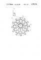
- FIG. 1is a top view of a multi-canister tinter having stirrers according to an embodiment of the invention.
- FIG. 2is a view taken in the direction II--II in FIG. 1.
- FIG. 3is a cross section of a canister and cap of one of the tinters of FIGS. 1 and 2.
- FIG. 3Ais a cross section taken along IIIA--IIIA in FIG. 3.
- FIG. 4is a side view of a portion of one of the tinters of FIGS. 1 and 2 with the cap in its operational position.
- FIG. 5is a side view corresponding to FIG. 4 with the cap hinged away from the top of its canister.
- a multi-canister tinter assemblyaccording to an embodiment of the invention.
- a plurality of identical tinters 12are disposed at equal angles about a perimeter of a rotary plate 14.
- twelve tinters 12are provided. More or less than twelve tinters 12 may be used.
- An orbit plate 16is driven by an eccentric drive mechanism to move a center 18 in an orbiting motion as indicated by a dashed circle 20.
- the eccentric drive mechanismis assumed to be conventional and may be of the type disclose in the referenced patent. Thus, further description thereof is unnecessary.
- a plurality of drive arms 22, equal in number to the number of tinters 12,are hingedly connected to a perimeter of orbit plate 16.
- a distal end of each of drive arms 22is operatively connected to its respective tinter 12.
- each tinter 12includes a canister 24 having a tinter pump 26 associated therewith.
- Tinter pump 26may be of any convenient type such as, for example, that disclosed or referenced in co-pending U.S. patent application Ser. No. 07/045,376 of common assignee with the present invention.
- tinter pump 26includes a horizontal-acting displacement pump 28 and a two-way valve 30.
- a knob 32controlling a dispensable amount of tinter fluid in a displacement chamber (not shown) is moved to a position guided by a scale 34.
- a handle 36 on two-way valve 30is moved to its dispensing position and knob 32 is pushed to its home position. As knob 32 is pushed to its home position, the dispensable amount of tinter fluid is dispensed through an outlet 38.
- each tinter 12is tied to its neighbor by brace tabs 40 and 42 engaged by a thumb screw 44. It will be noted that brace tabs 40 and 42 are disposed so that the upper surfaces of brace tab 40 abut the lower surfaces of their brace tabs 42. Referring momentarily to FIG. 1, the bracing provided by brace tabs 40 and 42 provide hoop strength by tying the tops of all tinters 12 together to form a closed circle.
- a cap 46 atop each canister 24includes a rim 48 and a cover 50. It will be noted that rim 48 has a diameter exceeding cover 50 to provide an abutment surface against which edges of thumb screw 44 may bear to hold cap 46 on place during operation. Although one skilled in the art would observe other ways of attaining engagement of thumb screw 44 with brace tabs 40 and 42, one o employs external threads on thumb screw 44 and complementary in a hole (not shown) in brace tab 40.
- canister 24includes an annular side wall 52 and a bottom 54.
- a socket 56is centrally disposed in bottom 54 for receiving a boss 58 extending thereinto from an impeller 60.
- Impeller 60includes a central vertical shaft 61 having a plurality of inclined vanes 63 extending horizontally therefrom at staggered locations along its length.
- a top bar 65extends horizontally from vertical shaft 61 toward an inner surface of annular side wall 52.
- An opening 62permits connection of tinter fluid from canister 24 to tinter pump 26 (FIG. 2).
- An inner member 64 of cap 46includes an annular wall 66 extending upward from a circular plate 68.
- Rim 48extends outward from circular plate 68.
- a groove 70 in a lower surface of rim 48embraces an upper end 72 of annular side wall 52.
- crank shaft 80is connected at its upper end to one end of a crank 82.
- Connection between crank shaft 80 and crank 82may employ any conventional technique such as cementing or welding but, in the preferred embodiment, one or more bosses 84 extend from an upper end of crank shaft 80 through mating holes in crank 82. Portions of bosses 84 extending beyond crank 82 are flattened to prevent withdrawal detachment.
- a hole 86 at an outer end of crank 82is engaged by a pin 88 affixed to drive arm 22.
- a window 89 covering approximately 180 degrees of cover 50permits entry of drive arm 22.
- a boss 90 atop drive arm 22provides a clearance between an upper surface 92 thereof and an inner surface of cover 50 which is less than the length of pin 88.
- top bar 65centrally connected to crank shaft 80, terminates in first and second driver bosses 96 and 98.
- the opposed ends of top bar 65include at least one tangential tab 100 and 102 facing against the direction of rotation of impeller 60. Curved ends 103 and 105 of top bar 65 are spaced closely enough to the inner surface of annular side wall 52 to permit initial misalignment of top bar 65 to be overcome.
- impeller 60may be placed in canister 24 with an arbitrary angular orientation with respect to circular plate 68. After less than 180 degrees of rotation of circular plate 68, driver bosses 96 and 98 are moved from their arbitrary disengaged position, shown in dashed line in FIG. 3A to their solid line position. The diameters of driver bosses 96 and 98, together with the radii on tangential tabs 100 and 102 are great enough to move top bar 65 into its centered position and thereafter to hold it there while urging impeller 60 in its rotary motion
- At least one, and preferably two, recesses 106 in annular wall 66permit deflection thereinto of staked portions 108 of a lower perimeter of cover 50. This provides a rapid and secure method for installing cover 50. It will be clear from the foregoing that, once cover 50 is installed, cap 46 becomes an integral unit hingedly attached by drive arm 22 to orbit plate 16.
- Drive arm 22includes a lower portion 110 having a pivot shaft 112 extending from each side thereof (only pivot shaft 112 is visible in the figure).
- a clamp 114secures each pivot shaft 112 to the surface of orbit plate 16.
- An offset portion 116is joined to lower portion 110 by a connecting portion 118. In this way, orbital motion of orbit plate 16 is transmitted directly to crank 82 (FIG. 3).
- cap 46is removed from canister 24 and hinged out of the way about pivot shaft 112 until a corner 120 joining offset portion 116 and connecting portion 118 contacts the upper surface of orbit plate 16. When this contact occurs, the center of gravity of the mass supported by pivot shaft 112 is over-center. Thus, the assembly tends to remain in the position shown, thereby clearing the top of canister 24 for filling or cleaning.
- driver bosses 96 and 98are not critical. If orbit plate 16 has remained stationary in the interim, driver bosses 96 and 98 will assume the same angular position they occupied when cap 46 was removed. Thus, engagement of grooves 100 in driver bosses 96 and 98 with pins 102 and 104 (FIG. 3) take place upon replacing cap 46. If orbit plate 16 has moved, driver bosses 96 and 98 will lie out of contact with driver bosses 96 and 98. However, within less than 180 degrees of orbital motion of orbit plate 16, driving contact will be established without requiring attention from an operator.
Landscapes
- Chemical & Material Sciences (AREA)
- Chemical Kinetics & Catalysis (AREA)
- Structures Of Non-Positive Displacement Pumps (AREA)
Abstract
Description
Claims (4)
Priority Applications (1)
| Application Number | Priority Date | Filing Date | Title |
|---|---|---|---|
| US07/052,381US4792236A (en) | 1987-05-21 | 1987-05-21 | Multi-canister tinter with lost-motion coupling |
Applications Claiming Priority (1)
| Application Number | Priority Date | Filing Date | Title |
|---|---|---|---|
| US07/052,381US4792236A (en) | 1987-05-21 | 1987-05-21 | Multi-canister tinter with lost-motion coupling |
Publications (1)
| Publication Number | Publication Date |
|---|---|
| US4792236Atrue US4792236A (en) | 1988-12-20 |
Family
ID=21977250
Family Applications (1)
| Application Number | Title | Priority Date | Filing Date |
|---|---|---|---|
| US07/052,381Expired - Fee RelatedUS4792236A (en) | 1987-05-21 | 1987-05-21 | Multi-canister tinter with lost-motion coupling |
Country Status (1)
| Country | Link |
|---|---|
| US (1) | US4792236A (en) |
Cited By (27)
| Publication number | Priority date | Publication date | Assignee | Title |
|---|---|---|---|---|
| US5558708A (en)* | 1995-05-11 | 1996-09-24 | C-Cure Corporation | System and method for dispersing pigment in cement based compositions |
| US5613775A (en)* | 1994-07-21 | 1997-03-25 | Fast S.P.A. | Apparatus for mixing liquid products to prepare coloring substances for paints and the like |
| US5711458A (en)* | 1996-01-22 | 1998-01-27 | Fluid Management, Inc. | Paint dispensing apparatus |
| US5846315A (en)* | 1995-05-11 | 1998-12-08 | C-Cure Corporation | Method for preparing a pigmented dispersing pigment cement composition |
| US6053218A (en)* | 1998-11-10 | 2000-04-25 | X-Pert Paint Mixing Systems, Inc. | Semi-automated system for dispensing automotive paint |
| US6095373A (en)* | 1998-11-10 | 2000-08-01 | X-Pert Paint Mixing Systems, Inc. | Paint container lid for a semi-automated automotive paint dispensing system |
| US6146009A (en)* | 1999-10-13 | 2000-11-14 | X-Pert Paint Mixing Systems, Inc. | Paint container lid member adaptable for use with a plurality of paint mixing systems |
| US6206250B1 (en) | 1999-10-13 | 2001-03-27 | X-Pert Paint Mixing Systems, Inc. | Lid member for a paint container useable with a semi-automated automotive paint dispensing system |
| US6230938B1 (en) | 1999-10-13 | 2001-05-15 | X-Pert Paint Mixing Systems, Inc. | Seal structure for a fluid pour spout of a paint container lid member |
| US6234218B1 (en) | 1999-10-13 | 2001-05-22 | X-Pert Paint Mixing Systems, Inc. | Semi-automated automotive paint dispensing system |
| US6692565B2 (en) | 2000-11-20 | 2004-02-17 | C-Cure Corp. | Colored cement |
| US20050194403A1 (en)* | 2004-02-27 | 2005-09-08 | Mink Johannes H. | Fluid and hair-dye dispensers |
| US20060000838A1 (en)* | 2004-06-02 | 2006-01-05 | Peter Santrach | Self-cleaning lid for a paint container fluid pour spout |
| US20080221386A1 (en)* | 1997-02-13 | 2008-09-11 | Gellman Barry N | Devices for minimally invasive pelvic surgery |
| US20100318220A1 (en)* | 2008-03-03 | 2010-12-16 | The Saranow Group, Llc | Blending station apparatus and method for using the same |
| US20110100504A1 (en)* | 2008-03-03 | 2011-05-05 | The Saranow Group, Llc | Blending station apparatus and method for using the same |
| US20110118781A1 (en)* | 2007-01-19 | 2011-05-19 | Cook James L | Method and suture-button construct for stabilization of cranial cruciate ligament deficient stifle |
| US8336582B2 (en) | 2008-03-03 | 2012-12-25 | Saranow Mitchell H | Method and system for the preparation of hair dye colors |
| US8393358B2 (en) | 2008-03-03 | 2013-03-12 | SureTint Technologies, LLC | Method for manual dispensing using standardized packaging |
| US20140299626A1 (en)* | 2011-02-03 | 2014-10-09 | Cps Color Equipment Spa Con Unicon Socio | Apparatus for the delivery of fluid products |
| US8897915B2 (en) | 2008-03-03 | 2014-11-25 | SureTint Technologies, LLC | Inventory security management for a hair dye storage system |
| US9177339B2 (en) | 2008-03-03 | 2015-11-03 | Sure Tint Technologies, LLC | System and method for color preparation and management |
| US9414665B2 (en) | 2008-03-03 | 2016-08-16 | SureTint Technologies, LLC | Blending color and control management system |
| US9877569B2 (en) | 2011-02-24 | 2018-01-30 | SureTint Technologies, LLC | System and method for batch sizing hair dye mixtures |
| US10897979B1 (en) | 2019-09-12 | 2021-01-26 | SureTint Technologies, LLC | System and method for hair dye color conversion |
| US11235298B2 (en) | 2008-03-03 | 2022-02-01 | SureTint Technologies, LLC | Blending station apparatus and method for using the same |
| US11246395B2 (en) | 2008-03-03 | 2022-02-15 | SureTint Technologies, LLC | Color conversion system and method |
Citations (7)
| Publication number | Priority date | Publication date | Assignee | Title |
|---|---|---|---|---|
| US920738A (en)* | 1909-01-12 | 1909-05-04 | Benjamin N Hawes | Butter-merger. |
| US1482279A (en)* | 1919-12-10 | 1924-01-29 | Josephine Trust | Mixing and beating machine |
| US1915220A (en)* | 1932-10-08 | 1933-06-20 | North Bros Mfg Co | Ice cream freezer |
| DE809346C (en)* | 1949-05-14 | 1951-07-30 | Jakob Wochinger | Dough and like agitator |
| US2736535A (en)* | 1953-04-24 | 1956-02-28 | William R Clark | Mixing device |
| US2905451A (en)* | 1958-03-28 | 1959-09-22 | Pure Oil Co | Mixing device |
| US2965363A (en)* | 1957-11-26 | 1960-12-20 | Air Hydraulics Inc | Paint mixing machine |
- 1987
- 1987-05-21USUS07/052,381patent/US4792236A/ennot_activeExpired - Fee Related
Patent Citations (7)
| Publication number | Priority date | Publication date | Assignee | Title |
|---|---|---|---|---|
| US920738A (en)* | 1909-01-12 | 1909-05-04 | Benjamin N Hawes | Butter-merger. |
| US1482279A (en)* | 1919-12-10 | 1924-01-29 | Josephine Trust | Mixing and beating machine |
| US1915220A (en)* | 1932-10-08 | 1933-06-20 | North Bros Mfg Co | Ice cream freezer |
| DE809346C (en)* | 1949-05-14 | 1951-07-30 | Jakob Wochinger | Dough and like agitator |
| US2736535A (en)* | 1953-04-24 | 1956-02-28 | William R Clark | Mixing device |
| US2965363A (en)* | 1957-11-26 | 1960-12-20 | Air Hydraulics Inc | Paint mixing machine |
| US2905451A (en)* | 1958-03-28 | 1959-09-22 | Pure Oil Co | Mixing device |
Cited By (61)
| Publication number | Priority date | Publication date | Assignee | Title |
|---|---|---|---|---|
| US5613775A (en)* | 1994-07-21 | 1997-03-25 | Fast S.P.A. | Apparatus for mixing liquid products to prepare coloring substances for paints and the like |
| US5558708A (en)* | 1995-05-11 | 1996-09-24 | C-Cure Corporation | System and method for dispersing pigment in cement based compositions |
| US5846315A (en)* | 1995-05-11 | 1998-12-08 | C-Cure Corporation | Method for preparing a pigmented dispersing pigment cement composition |
| US5855665A (en)* | 1995-05-11 | 1999-01-05 | C-Cure Corporation | System and method for producing a pigmented cement composition |
| US5951752A (en)* | 1995-05-11 | 1999-09-14 | C-Cure Corporation | Method of using a coloring composition in a concrete based composition |
| US5711458A (en)* | 1996-01-22 | 1998-01-27 | Fluid Management, Inc. | Paint dispensing apparatus |
| US20080221386A1 (en)* | 1997-02-13 | 2008-09-11 | Gellman Barry N | Devices for minimally invasive pelvic surgery |
| US6053218A (en)* | 1998-11-10 | 2000-04-25 | X-Pert Paint Mixing Systems, Inc. | Semi-automated system for dispensing automotive paint |
| US6095373A (en)* | 1998-11-10 | 2000-08-01 | X-Pert Paint Mixing Systems, Inc. | Paint container lid for a semi-automated automotive paint dispensing system |
| US6146009A (en)* | 1999-10-13 | 2000-11-14 | X-Pert Paint Mixing Systems, Inc. | Paint container lid member adaptable for use with a plurality of paint mixing systems |
| US6230938B1 (en) | 1999-10-13 | 2001-05-15 | X-Pert Paint Mixing Systems, Inc. | Seal structure for a fluid pour spout of a paint container lid member |
| US6234218B1 (en) | 1999-10-13 | 2001-05-22 | X-Pert Paint Mixing Systems, Inc. | Semi-automated automotive paint dispensing system |
| US6290110B1 (en) | 1999-10-13 | 2001-09-18 | X-Pert Paint Mixing Systems, Inc. | Fluid seal for a pour spout of a paint container lid member |
| US6474516B2 (en) | 1999-10-13 | 2002-11-05 | X-Pert Paint Mixing Systems, Inc. | Seal structure for a fluid pour spout of a paint container lid member |
| US6206250B1 (en) | 1999-10-13 | 2001-03-27 | X-Pert Paint Mixing Systems, Inc. | Lid member for a paint container useable with a semi-automated automotive paint dispensing system |
| US6755326B2 (en) | 1999-10-13 | 2004-06-29 | X-Pert Paint Mixing Systems, Inc. | Seal structure for a fluid pour spout of a paint container lid member |
| US6692565B2 (en) | 2000-11-20 | 2004-02-17 | C-Cure Corp. | Colored cement |
| US20060278663A1 (en)* | 2004-02-27 | 2006-12-14 | Lenteq, Lp | Valve actuator for a fluid dispenser |
| US20060191956A1 (en)* | 2004-02-27 | 2006-08-31 | Lenteq, Lp | Fluid and hair-dye dispensers |
| US7121430B2 (en) | 2004-02-27 | 2006-10-17 | Lentep, Lp | Fluid and hair-dye dispensers |
| US20060231578A1 (en)* | 2004-02-27 | 2006-10-19 | Lenteq, Lp | Fluid and hair-dye dispensers |
| US20060261090A1 (en)* | 2004-02-27 | 2006-11-23 | Lenteq, Lp | Fluid and hair dye dispensers having central support column |
| US20060261089A1 (en)* | 2004-02-27 | 2006-11-23 | Lenteq, Lp | Hair dye dispenser |
| US20060283889A1 (en)* | 2004-02-27 | 2006-12-21 | Lenteq, Lp | Two disc valve pump assembly for a fluid dispenser |
| US7185789B2 (en) | 2004-02-27 | 2007-03-06 | Lenteq, Lp | Hair dye dispenser |
| US20050194403A1 (en)* | 2004-02-27 | 2005-09-08 | Mink Johannes H. | Fluid and hair-dye dispensers |
| US7597217B2 (en) | 2004-02-27 | 2009-10-06 | Lenteq, Lp | Two disc valve pump assembly for a fluid dispenser |
| US20060000838A1 (en)* | 2004-06-02 | 2006-01-05 | Peter Santrach | Self-cleaning lid for a paint container fluid pour spout |
| US8424704B2 (en) | 2004-06-02 | 2013-04-23 | X-Pert Paint Mixing Systems, Inc. | Self-cleaning lid for a paint container fluid pour spout |
| US20110118781A1 (en)* | 2007-01-19 | 2011-05-19 | Cook James L | Method and suture-button construct for stabilization of cranial cruciate ligament deficient stifle |
| US20110100504A1 (en)* | 2008-03-03 | 2011-05-05 | The Saranow Group, Llc | Blending station apparatus and method for using the same |
| US9919278B2 (en) | 2008-03-03 | 2018-03-20 | SureTint Technologies, LLC | Blending station apparatus and method for using the same |
| US8393363B2 (en) | 2008-03-03 | 2013-03-12 | SureTint Technologies, LLC | Blending station apparatus and method for using the same |
| US8393358B2 (en) | 2008-03-03 | 2013-03-12 | SureTint Technologies, LLC | Method for manual dispensing using standardized packaging |
| US20100318220A1 (en)* | 2008-03-03 | 2010-12-16 | The Saranow Group, Llc | Blending station apparatus and method for using the same |
| US8567455B2 (en) | 2008-03-03 | 2013-10-29 | SureTint Technologies, LLC | Blending station apparatus and method for using the same |
| US12245680B2 (en) | 2008-03-03 | 2025-03-11 | B&R Holdings Llc | Color conversion system and method |
| US8897915B2 (en) | 2008-03-03 | 2014-11-25 | SureTint Technologies, LLC | Inventory security management for a hair dye storage system |
| US9177339B2 (en) | 2008-03-03 | 2015-11-03 | Sure Tint Technologies, LLC | System and method for color preparation and management |
| US11950683B2 (en) | 2008-03-03 | 2024-04-09 | B&R Holdings, Llc | Color conversion system and method |
| US9414665B2 (en) | 2008-03-03 | 2016-08-16 | SureTint Technologies, LLC | Blending color and control management system |
| US9524605B2 (en) | 2008-03-03 | 2016-12-20 | SureTint Technologies, LLC | System and method for color preparation and management |
| US9623388B2 (en) | 2008-03-03 | 2017-04-18 | SureTint Technologies, LLC | Blending station apparatus and method for using the same |
| US9839278B2 (en) | 2008-03-03 | 2017-12-12 | SureTint Technologies, LLC | Blending color and control management system |
| US11918964B2 (en) | 2008-03-03 | 2024-03-05 | SureTint Technologies, LLC | Blending station apparatus and method for using the same |
| US8336582B2 (en) | 2008-03-03 | 2012-12-25 | Saranow Mitchell H | Method and system for the preparation of hair dye colors |
| US10182638B2 (en) | 2008-03-03 | 2019-01-22 | SureTint Technologies, LLC | Blending color and control management system |
| US11246395B2 (en) | 2008-03-03 | 2022-02-15 | SureTint Technologies, LLC | Color conversion system and method |
| US10893740B2 (en) | 2008-03-03 | 2021-01-19 | SureTint Technologies, LLC | Color conversion system and method |
| US11235298B2 (en) | 2008-03-03 | 2022-02-01 | SureTint Technologies, LLC | Blending station apparatus and method for using the same |
| US11052359B2 (en) | 2008-03-03 | 2021-07-06 | SureTint Technologies, LLC | Blending station apparatus and method for using the same |
| US11103841B2 (en) | 2008-03-03 | 2021-08-31 | SureTint Technologies, LLC | Blending station apparatus and method for using the same |
| US9289734B2 (en)* | 2011-02-03 | 2016-03-22 | Cps Color Equipment Sa Con Unico Socio | Apparatus for the delivery of fluid products |
| US20140299626A1 (en)* | 2011-02-03 | 2014-10-09 | Cps Color Equipment Spa Con Unicon Socio | Apparatus for the delivery of fluid products |
| US10716386B2 (en) | 2011-02-24 | 2020-07-21 | SureTint Technologies, LLC | System and method for batch sizing hair dye mixtures |
| US11375801B2 (en) | 2011-02-24 | 2022-07-05 | SureTint Technologies, LLC | System and method for batch sizing hair dye mixtures |
| US9877569B2 (en) | 2011-02-24 | 2018-01-30 | SureTint Technologies, LLC | System and method for batch sizing hair dye mixtures |
| US10897979B1 (en) | 2019-09-12 | 2021-01-26 | SureTint Technologies, LLC | System and method for hair dye color conversion |
| US11344103B2 (en) | 2019-09-12 | 2022-05-31 | SureTint Technologies, LLC | System and method for hair dye color conversion |
| US11925251B2 (en) | 2019-09-12 | 2024-03-12 | SureTint Technologies, LLC | System and method for hair dye color conversion |
| US12408744B2 (en) | 2019-09-12 | 2025-09-09 | B&R Holdings, Llc | System and method for hair dye color conversion |
Similar Documents
| Publication | Publication Date | Title |
|---|---|---|
| US4792236A (en) | Multi-canister tinter with lost-motion coupling | |
| US7384188B2 (en) | Mixing lid having inner and outer paddles for mixing a liquid mixture in a container | |
| CA1280109C (en) | Paint mixing container | |
| CN103379953B (en) | Devices for dispensing multiple fluids | |
| JP3655003B2 (en) | Plug-in locking device for correctly attaching accessories to multi-component cartridges or dispensing devices | |
| US7217028B2 (en) | Off-axis goblet for food mixer | |
| US2894309A (en) | Container clamp for liquid mixing apparatus | |
| US5549384A (en) | Mixer with helically extending blades | |
| EP3332865B1 (en) | Stirrer for a viscous liquid | |
| NO941082D0 (en) | Mixers for mixing, especially of paint, lacquer and the like. | |
| HUT66245A (en) | Apparatus for mixing and preparing fusible materials | |
| US6390665B1 (en) | Spillage preventing blender | |
| CA2197114C (en) | Batching machine, in particular for dyes | |
| US6269978B1 (en) | Dispensing and dosing machine for dyestuffs | |
| KR20170138523A (en) | Mixer for fluid products | |
| US6991934B2 (en) | Tissue processor with integrated valve | |
| US7097348B2 (en) | Methods and apparatuses for mixing cosmetic preparations at a point of sale | |
| WO2011132290A1 (en) | Two-liquid mixing type injector | |
| AU2877797A (en) | Agitator cover for tinting box on paint mixing machines | |
| US4884245A (en) | Quick-connection drive coupling for mixing tank | |
| US3411756A (en) | Mixing device for fluids | |
| US5911342A (en) | Dye batching machine | |
| CN1130153C (en) | Household mixing appliance | |
| US5011045A (en) | Paint toner dispensing machine | |
| GB2045101A (en) | Supplying materials to a mixing chamber of a mechanical mixer |
Legal Events
| Date | Code | Title | Description |
|---|---|---|---|
| AS | Assignment | Owner name:RED DEVIL, INC., 2400 VAUXHAL RD., UNION, NEW JERS Free format text:ASSIGNMENT OF ASSIGNORS INTEREST.;ASSIGNORS:HEINIS, ROBERT;SKENE, JAMES C.;SMITH, RONALD;REEL/FRAME:004715/0709 Effective date:19870504 Owner name:RED DEVIL, INC., NEW JERSEY Free format text:ASSIGNMENT OF ASSIGNORS INTEREST;ASSIGNORS:HEINIS, ROBERT;SKENE, JAMES C.;SMITH, RONALD;REEL/FRAME:004715/0709 Effective date:19870504 | |
| AS | Assignment | Owner name:PHILADELPHIA NATIONAL BANK, INCORPORATED AS COREST Free format text:SECURITY INTEREST;ASSIGNOR:RED DEVIL, INCORPORATED, A CORP. OF NJ;REEL/FRAME:005895/0004 Effective date:19910613 | |
| FEPP | Fee payment procedure | Free format text:PAYOR NUMBER ASSIGNED (ORIGINAL EVENT CODE: ASPN); ENTITY STATUS OF PATENT OWNER: LARGE ENTITY | |
| FEPP | Fee payment procedure | Free format text:PAT HLDR NO LONGER CLAIMS SMALL ENT STAT AS SMALL BUSINESS (ORIGINAL EVENT CODE: LSM2); ENTITY STATUS OF PATENT OWNER: LARGE ENTITY | |
| AS | Assignment | Owner name:MELLON BANK, N.A., PENNSYLVANIA Free format text:ASSIGNMENT OF ASSIGNORS INTEREST.;ASSIGNOR:RED DEVIL INCORPORATED, A CORP. OF NJ;REEL/FRAME:005988/0331 Effective date:19911108 | |
| FPAY | Fee payment | Year of fee payment:4 | |
| AS | Assignment | Owner name:RED DEVIL, INCORPORATED, NEW JERSEY Free format text:ASSIGNMENT OF ASSIGNORS INTEREST;ASSIGNOR:MELLON BANK N.A.;REEL/FRAME:006709/0082 Effective date:19930913 | |
| REMI | Maintenance fee reminder mailed | ||
| LAPS | Lapse for failure to pay maintenance fees | ||
| FP | Lapsed due to failure to pay maintenance fee | Effective date:19961225 | |
| AS | Assignment | Owner name:CIT GROUP/BUSINESS CREDIT, INC., THE, NEW YORK Free format text:SECURITY INTEREST;ASSIGNOR:RED DEVIL, INC. A/K/A RED DEVIL, INCORPORATED;REEL/FRAME:013532/0257 Effective date:20021114 | |
| AS | Assignment | Owner name:RED DEVIL, INCORPORATED, NEW JERSEY Free format text:RELEASE OF SECURITY INTEREST;ASSIGNOR:CIT GROUP/BUSINESS CREDIT, INC., THE;REEL/FRAME:015027/0036 Effective date:20040213 | |
| STCH | Information on status: patent discontinuation | Free format text:PATENT EXPIRED DUE TO NONPAYMENT OF MAINTENANCE FEES UNDER 37 CFR 1.362 |