US4791372A - Conformable head or body coil assembly for magnetic imaging apparatus - Google Patents
Conformable head or body coil assembly for magnetic imaging apparatusDownload PDFInfo
- Publication number
- US4791372A US4791372AUS07/086,368US8636887AUS4791372AUS 4791372 AUS4791372 AUS 4791372AUS 8636887 AUS8636887 AUS 8636887AUS 4791372 AUS4791372 AUS 4791372A
- Authority
- US
- United States
- Prior art keywords
- assembly
- coil
- band
- specimen
- head
- Prior art date
- Legal status (The legal status is an assumption and is not a legal conclusion. Google has not performed a legal analysis and makes no representation as to the accuracy of the status listed.)
- Expired - Fee Related
Links
Images


Classifications
- G—PHYSICS
- G01—MEASURING; TESTING
- G01R—MEASURING ELECTRIC VARIABLES; MEASURING MAGNETIC VARIABLES
- G01R33/00—Arrangements or instruments for measuring magnetic variables
- G01R33/20—Arrangements or instruments for measuring magnetic variables involving magnetic resonance
- G01R33/28—Details of apparatus provided for in groups G01R33/44 - G01R33/64
- G01R33/32—Excitation or detection systems, e.g. using radio frequency signals
- G01R33/34—Constructional details, e.g. resonators, specially adapted to MR
- G01R33/341—Constructional details, e.g. resonators, specially adapted to MR comprising surface coils
- G—PHYSICS
- G01—MEASURING; TESTING
- G01R—MEASURING ELECTRIC VARIABLES; MEASURING MAGNETIC VARIABLES
- G01R33/00—Arrangements or instruments for measuring magnetic variables
- G01R33/20—Arrangements or instruments for measuring magnetic variables involving magnetic resonance
- G01R33/28—Details of apparatus provided for in groups G01R33/44 - G01R33/64
- G01R33/32—Excitation or detection systems, e.g. using radio frequency signals
- G01R33/34—Constructional details, e.g. resonators, specially adapted to MR
- G01R33/343—Constructional details, e.g. resonators, specially adapted to MR of slotted-tube or loop-gap type
- G—PHYSICS
- G01—MEASURING; TESTING
- G01R—MEASURING ELECTRIC VARIABLES; MEASURING MAGNETIC VARIABLES
- G01R33/00—Arrangements or instruments for measuring magnetic variables
- G01R33/20—Arrangements or instruments for measuring magnetic variables involving magnetic resonance
- G01R33/28—Details of apparatus provided for in groups G01R33/44 - G01R33/64
- G01R33/32—Excitation or detection systems, e.g. using radio frequency signals
- G01R33/34—Constructional details, e.g. resonators, specially adapted to MR
- G01R33/34084—Constructional details, e.g. resonators, specially adapted to MR implantable coils or coils being geometrically adaptable to the sample, e.g. flexible coils or coils comprising mutually movable parts
Definitions
- the present inventionis directed to a head or body coil assembly for picking up free induction decay or spin-echo signals from a test specimen (for example, human) produced by a magnetic resonance imaging (MRI) apparatus. More particularly, it is suitable for test specimens of varying diameter configuration.
- MRImagnetic resonance imaging
- Head or body coilsare necessary in MRI apparatus. They are commonly used both for providing radio frequency (RF) excitation signals and thereafter receiving a spin-echo or free induction decay signal indicating a characteristic of the specimen being examined. Since the so-called pickup signal is of a very small magnitude, it is important to maximize the signal above the ambient noise level. It is also desirable that the specimen or human patient (which inevitably comes in various sizes and shapes, depending on the body portion being imaged) uniformly fill the coil structure in an optimal manner.
- RFradio frequency
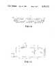
- FIG. 5illustrates a prior art coil of the saddle type where two separate coils provide a magnetic field vector B1 through the effective centers of the coils with the main magnetic field, Bo, lying along a centerline.
- the associated Velcro fasteningthus shifts the field vector depending on the size of the body portion.
- a head or body coil assemblyfor picking up free induction decay or spin-echo signals from a test specimen produced in a magnetic resonance imaging apparatus. It comprises an inductive pickup coil means for substantially surrounding the test specimen, including a thin, flexible, unitary, continuous band of conductive material substantially entirely covered with a flexible protective material.
- the bandhas a pair of ends with their facing interiors being provided with mutually adhering surfaces which, when fastened together, provides a conforming fit of the band around the specimens of varying diameter and configuration.
- FIG. 1is a perspective view showing a head coil assembly in use on a human patient.
- FIG. 2is a simplified plan view of an inductive pickup coil embodying the present invention.
- FIG. 3is a cross section taken along line 3--3 of FIG. 2.
- FIG. 4is a circuit schematic showing the overall circuit of the assembly embodying the present invention.
- FIG. 5is a perspective view of a prior art coil.
- FIG. 6is a simplified perspective view of the coil of FIG. 1.
- FIG. 1illustrates the inductive pickup coil 10 as it is surrounding the test specimen which, in this case, is a human head 11.
- the pickup coilconsists of a band of copper metal 12 in the form of a very thin flexible sheet which is covered by a sleeve 13 of cloth material. This is both for insulating purposes and for the patient's comfort.
- a flexible nonmagnetic material 14wrapped around the head 11, around which the coil 10 is placed. For example, it might be a sponge-like material.
- the two ends of the pickup coil 10which are designated 16 and 17 have adhered or placed on their interior facing portions a hook and loop type fastener 16a, 16b, such as VELCRO.
- a hook and loop type fastener 16a, 16bsuch as VELCRO.
- Thiscauses the flexible pickup coil 10 to adhere or provide a conforming fit around the head 11, or for that matter any other body part, and to accommodate varying configurations and diameters.
- a plastic clip 18can be provided where the force causing the two ends 16 and 17 to pull apart would be greatest.
- the pickup coilit is formed of a continuous band of thin copper material 12 (or any other conductive material), is substantially entirely covered with protective cloth 13, and by the use of VELCRO fastening 16a and 16b provides a conforming fit.
- the ends 16 and 17are electrically connected to a capacitive tuning unit 21 by means of the connector block 22 into which the ends and specifically the metallic band portions are inserted and held. This provides a very low resistance connection to allow easy tuning of the LC portions of the circuit to a resonance condition.
- the capacitive tuning unit 21contains as shown two adjustments--one for parallel capacitance C p and one for series capacitance C s . It is located on the same platform 22 as is the patient's head 11 and the coil 10.
- Unit 21compensates for the resistive loading caused by the specimen and especially specimens of different resistive values.
- the resonance condition of the circuitis adjusted so that, as is well known in MRI technology, the circuit is adjusted toward the resonance of the particular Larmor frequency being picked up.
- the output of capacitive tuning unit 21is a coaxial cable 23 which extends to the remaining processing circuitry. Details of this, such as an electronic switch by which an RF excitation pulse can be provided to the coil, and also a phase detector by which tuning can be more effectively accomplished is illustrated in the co-pending application Ser. No. 890,603 filed July 25, 1986, with James G. Holbrook and Otto J. Jaks as inventors entitled "Head or Body Coil Assembly for Magnetic Resonance Imaging Apparatus," and assigned to the present assignee. In that application a continuous band of conductive material is also utilized as the pickup coil. However, there is no specific closure or fastener shown and in its preferred embodiment it is a fixed type of structure. In the above application tuning is accomplished in two steps with a proximate unit to the coil and then a remote unit at the end of a transmission line or coaxial cable.
- FIG. 3shows the cloth material 13 covering the copper sheet 12 with the cloth of course being sewn together or fixed by glue at its ends 24 and 26.
- the overall circuit of the assemblyis illustrated in FIG. 4 with the pickup coil itself having an inductance L and a capacitance C which is generally due to the adhered ends 16 and 17.
- the tuning unit 21is shown in dashed outline as including the tunable series capacitor C s and the parallel capacitor C p .
- this tuningis accomplished, as discussed briefly above in connection with the co-pending application, by utilizing a phase detector to tune a signal for a maximum amplitude and an in phase condition.
- the improved head or body coil of the present inventionwhile conforming to fit around the head or other body part, does so while still maintaining an efficient and minimum loading configuration with relation to magnetic field B 1 vs. current, J.
- the geometrical axis 20 of the cylindrical configuration of coil 10should always substantially coincide with the solenoidal magnetic field axis B 1 produced by current, J, flowing in the coil or in response to a magnetic field in the direction indicated.
- the main magnetic fieldis shown in Bo.
- the active part of the pickup coilis the cylindrical conforming part with the remaining excess ends 16 and the 17 merely acting as a capacitor which can easily be compensated for.
- the effective pickup portion or the cylindrical solenoidal portionis the conforming part of the coil.
- the width of the coilcan also be adjusted for greatest efficiency and minimum loading if desired by choosing different width strips. Loading is minimized by limiting the RF magnetic field strength at locations of the specimen above or below the coil cylinder (N 2-3 strip widths). This reduces the power dissipation from induced eddy currents in the body, which reduces thermal noise.
- the foregoing choosing of the widthmust, of course, be consistent with a desired imaging field of view.
- the prior art showing in FIG. 5has a pickup or transmission coil which has its magnetic field B in a direction where the field vector is through the effective centers of the two coils.
- this coilis used in a magnetic resonance imaging machine of the supercooled type where the major magnetic field is in a direction different from that of the non-supercooled machine in which the present invention is utilized.
- the magnetic field B 1 in the present inventionis parallel to the Z or body axis of a patient, whereas in the "saddle type" coil of FIG. 5 it is perpendicular.
- the coil in FIG. 5does include a Velcro fastener but of a different type where one Velcro covered strap overlaps another so that the active ends of the coils themselves may never overlap.
- the ideal alignment of the coils 31 and 32is with the center of the coils (through which B 1 passes) 180 phase degrees apart and with edge to edge spacing of 60° (of the adjacent coil edges) for maximum magnetic field uniformity. This alignment is only applicable at one adjustment of the closure and thus other closures are either inefficient or cause errors.
Landscapes
- Physics & Mathematics (AREA)
- Condensed Matter Physics & Semiconductors (AREA)
- General Physics & Mathematics (AREA)
- Magnetic Resonance Imaging Apparatus (AREA)
Abstract
Description
Claims (7)
Priority Applications (3)
| Application Number | Priority Date | Filing Date | Title |
|---|---|---|---|
| US07/086,368US4791372A (en) | 1987-08-17 | 1987-08-17 | Conformable head or body coil assembly for magnetic imaging apparatus |
| EP88306602AEP0304165A1 (en) | 1987-08-17 | 1988-07-19 | Conformable head or body coil assembly for magnetic imaging apparatus |
| JP63204556AJPS6462146A (en) | 1987-08-17 | 1988-08-17 | Adaptable coil assembly in magnetic imaging apparatus for head or body of a person |
Applications Claiming Priority (1)
| Application Number | Priority Date | Filing Date | Title |
|---|---|---|---|
| US07/086,368US4791372A (en) | 1987-08-17 | 1987-08-17 | Conformable head or body coil assembly for magnetic imaging apparatus |
Publications (1)
| Publication Number | Publication Date |
|---|---|
| US4791372Atrue US4791372A (en) | 1988-12-13 |
Family
ID=22198117
Family Applications (1)
| Application Number | Title | Priority Date | Filing Date |
|---|---|---|---|
| US07/086,368Expired - Fee RelatedUS4791372A (en) | 1987-08-17 | 1987-08-17 | Conformable head or body coil assembly for magnetic imaging apparatus |
Country Status (3)
| Country | Link |
|---|---|
| US (1) | US4791372A (en) |
| EP (1) | EP0304165A1 (en) |
| JP (1) | JPS6462146A (en) |
Cited By (36)
| Publication number | Priority date | Publication date | Assignee | Title |
|---|---|---|---|---|
| WO1989004971A1 (en)* | 1987-11-25 | 1989-06-01 | Fonar Corporation | Solenoidal surface coils for magnetic resonance imaging |
| US5063933A (en)* | 1987-06-29 | 1991-11-12 | Kabushiki Kaisha Toshiba | Magnetic resonance imaging apparatus |
| US5143068A (en)* | 1990-11-26 | 1992-09-01 | Resonex, Inc. | Flexible and curved radio frequency (RF) coil for the human shoulder for magnetic resonance imaging apparatus |
| EP0579300A3 (en)* | 1992-06-22 | 1994-03-02 | Koninkl Philips Electronics Nv | |
| USD347475S (en) | 1992-02-21 | 1994-05-31 | Meacham Kenneth S | Magnetic resonance imaging coil bracket |
| US5339033A (en)* | 1992-08-11 | 1994-08-16 | Alliance Pharmaceutical Corp. | Method of improving fat saturation during MRI |
| US5390672A (en)* | 1993-10-08 | 1995-02-21 | Board Of Regents Univ. Of Nebraska | NMR liver coil |
| US5400787A (en)* | 1993-11-24 | 1995-03-28 | Magna-Lab, Inc. | Inflatable magnetic resonance imaging sensing coil assembly positioning and retaining device and method for using the same |
| US5435302A (en)* | 1988-09-09 | 1995-07-25 | Medrad, Inc. | Flexible surface coils for use in nuclear magnetic resonance imaging |
| US5519321A (en)* | 1993-06-01 | 1996-05-21 | Siemens Aktiengesellschaft | Circularly polarizing local antenna arrangement with a movable antenna |
| US5542424A (en)* | 1993-03-25 | 1996-08-06 | Rochester Institute Of Technology | Resonator for magnetic resonance imaging |
| US5577503A (en)* | 1991-12-04 | 1996-11-26 | Apogee Medical Products, Inc. | Apparatus and method for use in medical imaging |
| EP0753758A1 (en)* | 1995-07-11 | 1997-01-15 | Picker International, Inc. | Flexible nuclear magnetic resonance receiver coils and systems |
| US5663646A (en)* | 1995-03-30 | 1997-09-02 | Siemens Aktiengesellschaft | Head antenna for nuclear magnetic resonance examinations |
| US5905378A (en)* | 1997-02-13 | 1999-05-18 | General Electric Company | Flexible lightweight attached phased-array (FLAP) receive coils |
| US6044289A (en)* | 1991-12-04 | 2000-03-28 | Bonutti; Peter M. | Apparatus and method for controlling bending of a joint of a patient during imaging |
| US6054858A (en)* | 1997-01-27 | 2000-04-25 | General Electric Company | Method to automatically tune MRI RF coils |
| US6198961B1 (en)* | 1998-11-12 | 2001-03-06 | Picker International, Inc. | Interventional radio frequency coil assembly for magnetic resonance (MR) guided neurosurgery |
| US6263229B1 (en) | 1998-11-13 | 2001-07-17 | Johns Hopkins University School Of Medicine | Miniature magnetic resonance catheter coils and related methods |
| US20030052665A1 (en)* | 2001-09-17 | 2003-03-20 | Duggan Rodney James | Distributorless ignition adapter for diagnostic oscilloscopes |
| US6549800B1 (en) | 1996-04-25 | 2003-04-15 | Johns Hopkins Unversity School Of Medicine | Methods for in vivo magnetic resonance imaging |
| US6606513B2 (en) | 2000-02-01 | 2003-08-12 | Surgi-Vision, Inc. | Magnetic resonance imaging transseptal needle antenna |
| EP1337867A2 (en)* | 2000-11-09 | 2003-08-27 | Philips Medical Systems (Cleveland), Inc. | Mri rf coil systems having detachable, relocatable, and/or interchangeable sections and mri imaging systems and methods employing the same |
| US6628980B2 (en) | 2000-03-24 | 2003-09-30 | Surgi-Vision, Inc. | Apparatus, systems, and methods for in vivo magnetic resonance imaging |
| US6675033B1 (en) | 1999-04-15 | 2004-01-06 | Johns Hopkins University School Of Medicine | Magnetic resonance imaging guidewire probe |
| US6684096B2 (en)* | 2000-12-15 | 2004-01-27 | Berndt P. Schmit | Restraining apparatus and method for use in imaging procedures |
| US6684095B1 (en) | 1991-12-04 | 2004-01-27 | Bonutti 2003 Trust-A | Method of imaging a knee joint in a patient's leg with an imaging unit |
| US6898454B2 (en) | 1996-04-25 | 2005-05-24 | The Johns Hopkins University | Systems and methods for evaluating the urethra and the periurethral tissues |
| US20060167492A1 (en)* | 2005-01-24 | 2006-07-27 | Prince Martin R | Tourniquet for magnetic resonance angiography, and method of using same |
| US20060173390A1 (en)* | 2005-01-31 | 2006-08-03 | Robert Van Wyk | Immobilizing assembly and methods for use in diagnostic and therapeutic procedures |
| US7236816B2 (en) | 1996-04-25 | 2007-06-26 | Johns Hopkins University | Biopsy and sampling needle antennas for magnetic resonance imaging-guided biopsies |
| WO2008114195A3 (en)* | 2007-03-20 | 2008-11-20 | Koninkl Philips Electronics Nv | Rf receiver for an mri system comprising a susceptibility matched padding device |
| US20090012389A1 (en)* | 2007-07-05 | 2009-01-08 | Thomas Kundner | Arrangement and support device for attaching local coils in a magnetic resonance apparatus |
| US7848788B2 (en) | 1999-04-15 | 2010-12-07 | The Johns Hopkins University | Magnetic resonance imaging probe |
| US20130066362A1 (en)* | 2006-04-27 | 2013-03-14 | Vueklar Cardiovascular Ltd. | Occluder |
| US20180017643A1 (en)* | 2016-07-13 | 2018-01-18 | Stephan Zink | Size-variable local coil matrix with variable decoupling |
Families Citing this family (3)
| Publication number | Priority date | Publication date | Assignee | Title |
|---|---|---|---|---|
| US4882540A (en)* | 1988-06-28 | 1989-11-21 | Resonex, Inc. | Magnetic resonance imaging (MRI)apparatus with quadrature radio frequency (RF) coils |
| DE19509020A1 (en)* | 1995-03-13 | 1996-09-19 | Siemens Ag | Local antenna for magnetic resonance diagnosis |
| KR100404365B1 (en)* | 1999-09-09 | 2003-11-03 | 전인 | Pick-up apparatus for detecting resonance signal at outside of object |
Citations (6)
| Publication number | Priority date | Publication date | Assignee | Title |
|---|---|---|---|---|
| JPS6159806A (en)* | 1984-08-31 | 1986-03-27 | Hitachi Ltd | High-frequency coil for nmr imaging device |
| US4617936A (en)* | 1985-08-08 | 1986-10-21 | North American Philips Corporation | Flexible surface coil for magnetic resonance imaging |
| US4621237A (en)* | 1982-06-28 | 1986-11-04 | Oxford Research Systems Limited | Radiofrequency transducer and method of using same |
| US4636730A (en)* | 1984-08-16 | 1987-01-13 | General Electric Company | NMR spectroscopy body probes with at least one surface coil |
| WO1987001199A1 (en)* | 1985-08-14 | 1987-02-26 | Picker International Inc. | Surface coil system for magnetic resonance imaging |
| US4680549A (en)* | 1984-01-20 | 1987-07-14 | Instrumentarium Corp. | NMR coil arrangement |
Family Cites Families (4)
| Publication number | Priority date | Publication date | Assignee | Title |
|---|---|---|---|---|
| FR2481102A1 (en)* | 1980-04-29 | 1981-10-30 | Montagex | Automatic blood-pressure measurement and display appts. - uses piezoelectric sensor and electric pressure sensor connected to inflatable wrist cuff |
| FR2514633A1 (en)* | 1981-10-20 | 1983-04-22 | Saint Nicolas Cie Financiere | Combined sphygmomanometer and electrocardiograph mounted on bracelet - has electrode in casing and second electrode in form of conductive pushbutton pressed by hand of other wrist of patient |
| DE3324639C2 (en)* | 1983-07-08 | 1987-01-15 | Institut für Rundfunktechnik GmbH, 8000 München | Arrangement for generating a homogeneous magnetic field |
| FR2592297A1 (en)* | 1985-12-27 | 1987-07-03 | Spengler Ets E | Improvements to sphygmomanometers |
- 1987
- 1987-08-17USUS07/086,368patent/US4791372A/ennot_activeExpired - Fee Related
- 1988
- 1988-07-19EPEP88306602Apatent/EP0304165A1/ennot_activeWithdrawn
- 1988-08-17JPJP63204556Apatent/JPS6462146A/enactivePending
Patent Citations (6)
| Publication number | Priority date | Publication date | Assignee | Title |
|---|---|---|---|---|
| US4621237A (en)* | 1982-06-28 | 1986-11-04 | Oxford Research Systems Limited | Radiofrequency transducer and method of using same |
| US4680549A (en)* | 1984-01-20 | 1987-07-14 | Instrumentarium Corp. | NMR coil arrangement |
| US4636730A (en)* | 1984-08-16 | 1987-01-13 | General Electric Company | NMR spectroscopy body probes with at least one surface coil |
| JPS6159806A (en)* | 1984-08-31 | 1986-03-27 | Hitachi Ltd | High-frequency coil for nmr imaging device |
| US4617936A (en)* | 1985-08-08 | 1986-10-21 | North American Philips Corporation | Flexible surface coil for magnetic resonance imaging |
| WO1987001199A1 (en)* | 1985-08-14 | 1987-02-26 | Picker International Inc. | Surface coil system for magnetic resonance imaging |
Cited By (52)
| Publication number | Priority date | Publication date | Assignee | Title |
|---|---|---|---|---|
| US5063933A (en)* | 1987-06-29 | 1991-11-12 | Kabushiki Kaisha Toshiba | Magnetic resonance imaging apparatus |
| US4887038A (en)* | 1987-11-25 | 1989-12-12 | Fonar Corporation | Solenoidal surface coils for magnetic resonance imaging |
| WO1989004971A1 (en)* | 1987-11-25 | 1989-06-01 | Fonar Corporation | Solenoidal surface coils for magnetic resonance imaging |
| US5435302A (en)* | 1988-09-09 | 1995-07-25 | Medrad, Inc. | Flexible surface coils for use in nuclear magnetic resonance imaging |
| US5143068A (en)* | 1990-11-26 | 1992-09-01 | Resonex, Inc. | Flexible and curved radio frequency (RF) coil for the human shoulder for magnetic resonance imaging apparatus |
| US6684095B1 (en) | 1991-12-04 | 2004-01-27 | Bonutti 2003 Trust-A | Method of imaging a knee joint in a patient's leg with an imaging unit |
| US20040133097A1 (en)* | 1991-12-04 | 2004-07-08 | Bonutti Peter M. | Apparatus and method for use in medical imaging |
| US6044289A (en)* | 1991-12-04 | 2000-03-28 | Bonutti; Peter M. | Apparatus and method for controlling bending of a joint of a patient during imaging |
| US6882877B2 (en) | 1991-12-04 | 2005-04-19 | Bonutti Research, Inc. | Magnetic resonance imaging system and method |
| US5577503A (en)* | 1991-12-04 | 1996-11-26 | Apogee Medical Products, Inc. | Apparatus and method for use in medical imaging |
| USD347475S (en) | 1992-02-21 | 1994-05-31 | Meacham Kenneth S | Magnetic resonance imaging coil bracket |
| EP0579300A3 (en)* | 1992-06-22 | 1994-03-02 | Koninkl Philips Electronics Nv | |
| US5414358A (en)* | 1992-08-11 | 1995-05-09 | Alliance Pharmaceutical Corp. | Method of improving fat saturation during MRI |
| US5339033A (en)* | 1992-08-11 | 1994-08-16 | Alliance Pharmaceutical Corp. | Method of improving fat saturation during MRI |
| US5542424A (en)* | 1993-03-25 | 1996-08-06 | Rochester Institute Of Technology | Resonator for magnetic resonance imaging |
| US5519321A (en)* | 1993-06-01 | 1996-05-21 | Siemens Aktiengesellschaft | Circularly polarizing local antenna arrangement with a movable antenna |
| US5390672A (en)* | 1993-10-08 | 1995-02-21 | Board Of Regents Univ. Of Nebraska | NMR liver coil |
| US5400787A (en)* | 1993-11-24 | 1995-03-28 | Magna-Lab, Inc. | Inflatable magnetic resonance imaging sensing coil assembly positioning and retaining device and method for using the same |
| US5663646A (en)* | 1995-03-30 | 1997-09-02 | Siemens Aktiengesellschaft | Head antenna for nuclear magnetic resonance examinations |
| EP0753758A1 (en)* | 1995-07-11 | 1997-01-15 | Picker International, Inc. | Flexible nuclear magnetic resonance receiver coils and systems |
| US6549800B1 (en) | 1996-04-25 | 2003-04-15 | Johns Hopkins Unversity School Of Medicine | Methods for in vivo magnetic resonance imaging |
| US7778682B2 (en) | 1996-04-25 | 2010-08-17 | Johns Hopkins University | Biopsy and sampling needle antennas for magnetic resonance imaging-guided biopsies |
| US6898454B2 (en) | 1996-04-25 | 2005-05-24 | The Johns Hopkins University | Systems and methods for evaluating the urethra and the periurethral tissues |
| US7599729B2 (en) | 1996-04-25 | 2009-10-06 | The Johns Hopkins University | Evaluating the urethra and the periurethral tissues |
| US7236816B2 (en) | 1996-04-25 | 2007-06-26 | Johns Hopkins University | Biopsy and sampling needle antennas for magnetic resonance imaging-guided biopsies |
| US6184684B1 (en) | 1997-01-27 | 2001-02-06 | General Electric Company | Method to automatically tune MRI RF coils |
| US6054858A (en)* | 1997-01-27 | 2000-04-25 | General Electric Company | Method to automatically tune MRI RF coils |
| US6084411A (en)* | 1997-02-13 | 2000-07-04 | General Electric Company | Flexible lightweight attached phased-array (FLAP) receive coils |
| US5905378A (en)* | 1997-02-13 | 1999-05-18 | General Electric Company | Flexible lightweight attached phased-array (FLAP) receive coils |
| US6198961B1 (en)* | 1998-11-12 | 2001-03-06 | Picker International, Inc. | Interventional radio frequency coil assembly for magnetic resonance (MR) guided neurosurgery |
| US6263229B1 (en) | 1998-11-13 | 2001-07-17 | Johns Hopkins University School Of Medicine | Miniature magnetic resonance catheter coils and related methods |
| US6675033B1 (en) | 1999-04-15 | 2004-01-06 | Johns Hopkins University School Of Medicine | Magnetic resonance imaging guidewire probe |
| US7848788B2 (en) | 1999-04-15 | 2010-12-07 | The Johns Hopkins University | Magnetic resonance imaging probe |
| US7551953B2 (en) | 1999-04-15 | 2009-06-23 | Surgivision, Inc. | Magnetic resonance imaging needle antennas |
| US6606513B2 (en) | 2000-02-01 | 2003-08-12 | Surgi-Vision, Inc. | Magnetic resonance imaging transseptal needle antenna |
| US6628980B2 (en) | 2000-03-24 | 2003-09-30 | Surgi-Vision, Inc. | Apparatus, systems, and methods for in vivo magnetic resonance imaging |
| EP1337867A2 (en)* | 2000-11-09 | 2003-08-27 | Philips Medical Systems (Cleveland), Inc. | Mri rf coil systems having detachable, relocatable, and/or interchangeable sections and mri imaging systems and methods employing the same |
| US6684096B2 (en)* | 2000-12-15 | 2004-01-27 | Berndt P. Schmit | Restraining apparatus and method for use in imaging procedures |
| US6825648B2 (en)* | 2001-09-17 | 2004-11-30 | Rodney James Duggan | Distributorless ignition adapter for diagnostic oscilloscopes |
| US20030052665A1 (en)* | 2001-09-17 | 2003-03-20 | Duggan Rodney James | Distributorless ignition adapter for diagnostic oscilloscopes |
| US8190236B2 (en)* | 2005-01-24 | 2012-05-29 | Prince Martin R | Tourniquet for magnetic resonance angiography, and method of using same |
| US20060167492A1 (en)* | 2005-01-24 | 2006-07-27 | Prince Martin R | Tourniquet for magnetic resonance angiography, and method of using same |
| US11678890B2 (en)* | 2005-01-24 | 2023-06-20 | Martin R. Prince | Tourniquet for magnetic resonance angiography, and method of using same |
| US20130030284A1 (en)* | 2005-01-24 | 2013-01-31 | Prince Martin R | Tourniquet for magnetic resonance angiography, and method of using same |
| US20060173390A1 (en)* | 2005-01-31 | 2006-08-03 | Robert Van Wyk | Immobilizing assembly and methods for use in diagnostic and therapeutic procedures |
| US8932311B2 (en)* | 2006-04-27 | 2015-01-13 | Vueklar Cardiovascular Ltd. | Occluder |
| US20130066362A1 (en)* | 2006-04-27 | 2013-03-14 | Vueklar Cardiovascular Ltd. | Occluder |
| WO2008114195A3 (en)* | 2007-03-20 | 2008-11-20 | Koninkl Philips Electronics Nv | Rf receiver for an mri system comprising a susceptibility matched padding device |
| US7965081B2 (en)* | 2007-07-05 | 2011-06-21 | Siemens Aktiengesellschaft | Arrangement and support device for attaching local coils in a magnetic resonance apparatus |
| US20090012389A1 (en)* | 2007-07-05 | 2009-01-08 | Thomas Kundner | Arrangement and support device for attaching local coils in a magnetic resonance apparatus |
| US20180017643A1 (en)* | 2016-07-13 | 2018-01-18 | Stephan Zink | Size-variable local coil matrix with variable decoupling |
| US10641849B2 (en)* | 2016-07-13 | 2020-05-05 | Siemens Healthcare Gmbh | Size-variable local coil matrix with variable decoupling |
Also Published As
| Publication number | Publication date |
|---|---|
| JPS6462146A (en) | 1989-03-08 |
| EP0304165A1 (en) | 1989-02-22 |
Similar Documents
| Publication | Publication Date | Title |
|---|---|---|
| US4791372A (en) | Conformable head or body coil assembly for magnetic imaging apparatus | |
| US5905378A (en) | Flexible lightweight attached phased-array (FLAP) receive coils | |
| US4920318A (en) | Surface coil system for magnetic resonance imaging | |
| US6396271B1 (en) | Tunable birdcage transmitter coil | |
| US5143068A (en) | Flexible and curved radio frequency (RF) coil for the human shoulder for magnetic resonance imaging apparatus | |
| EP0388451B1 (en) | Quadrature surface coils for magnetic resonance imaging | |
| US4887038A (en) | Solenoidal surface coils for magnetic resonance imaging | |
| FI73320C (en) | NMR SPOLARRANGEMANG. | |
| US5990681A (en) | Low-cost, snap-in whole-body RF coil with mechanically switchable resonant frequencies | |
| US20060006865A1 (en) | Method and apparatus for magnetic resonance imaging and spectroscopy using microstrip transmission line coils | |
| US5689189A (en) | Technique for designing distributed radio frequency coils and distributed radio frequency coils designed thereby | |
| EP0256520A2 (en) | NMR local coil network | |
| US4839595A (en) | Magnetic resonance apparatus with a decoupling detection surface coil | |
| US6404199B1 (en) | Quadrature RF coil for vertical field MRI systems | |
| US5585721A (en) | Inductively coupled dedicated RF coils for MRI | |
| IL84884A (en) | Magnetic resonance imaging apparatus comprising an activatable birdcage rf coil | |
| US5329233A (en) | Cylindrical local coil for nuclear magnetic resonance imaging | |
| EP0356182A3 (en) | Coil assembly especially for magnetic resonance apparatus | |
| JPH01259848A (en) | Magnetic resonance apparatus | |
| JPS63309248A (en) | MRI surface coil device | |
| US5343862A (en) | NMR shoulder coil | |
| US5543710A (en) | NMR conformal solenoidal coil | |
| US5363113A (en) | Electromagnetic antenna and excitation antenna provided with such electromagnetic antenna for a nuclear magnetic resonance apparatus | |
| US4613837A (en) | Multiple feed Rf coils | |
| US4817612A (en) | Cross-coupled double loop receiver coil for NMR imaging of cardiac and thoraco-abdominal regions of the human body |
Legal Events
| Date | Code | Title | Description |
|---|---|---|---|
| AS | Assignment | Owner name:RESONEX, INC., 720 PALOMAR AVE., SUNNYVALE, CALIFO Free format text:ASSIGNMENT OF ASSIGNORS INTEREST.;ASSIGNORS:KIRK, GREGORY L.;MEWBORNE, JEFFREY D.;PARISH, DAVID M.;REEL/FRAME:004800/0325 Effective date:19870930 Owner name:RESONEX, INC., 720 PALOMAR AVE., SUNNYVALE, CALIFO Free format text:ASSIGNMENT OF ASSIGNORS INTEREST;ASSIGNORS:KIRK, GREGORY L.;MEWBORNE, JEFFREY D.;PARISH, DAVID M.;REEL/FRAME:004800/0325 Effective date:19870930 | |
| AS | Assignment | Owner name:BOND, CORNELIUS C. JR. Free format text:SECURITY INTEREST;ASSIGNOR:RESONEX, INC.;REEL/FRAME:004968/0065 Effective date:19881025 | |
| AS | Assignment | Owner name:TECHNOLOGY FUNDING SECURED INVESTORS II, A CA LIMI Free format text:SECURITY INTEREST;ASSIGNOR:RESONEX, INC., A CA CORP.;REEL/FRAME:005475/0542 Effective date:19900810 | |
| AS | Assignment | Owner name:LEVINTHAL, ELLIOTT, CALIFORNIA Free format text:RELEASED BY SECURED PARTY;ASSIGNOR:BOND, CORNELIUS;REEL/FRAME:005503/0631 Effective date:19881025 | |
| AS | Assignment | Owner name:TECHNOLOGY FUNDING SECURED INVESTORS II, 2000 ALAM Free format text:SECURITY INTEREST;ASSIGNOR:RESONEX, INC., A CORP. OF CA;REEL/FRAME:005578/0150 Effective date:19910123 | |
| AS | Assignment | Owner name:TECHNOLOGY FUNDING SECURED INVESTORS II, CALIFORNI Free format text:SECURITY INTEREST;ASSIGNOR:RESONEX, INC.;REEL/FRAME:005916/0306 Effective date:19911011 | |
| FPAY | Fee payment | Year of fee payment:4 | |
| AS | Assignment | Owner name:TECHNOLOGY FUNDING SECURED INVESTORS II Free format text:TO AMEND THE DEFINITION OF THE LOAN AGREEMENT IN A SECURITY AGREEMENT RECORDED AT REEL 5475, FRAME 0542.;ASSIGNOR:RESONEX, INC. A CORP. OF CALIFORNIA;REEL/FRAME:006147/0829 Effective date:19920612 | |
| AS | Assignment | Owner name:TECHNOLOGY FUNDING SEC. IN. II, CALIFORNIA Free format text:SECURITY INTEREST;ASSIGNOR:RESONEX, INC.;REEL/FRAME:006336/0921 Effective date:19921124 | |
| AS | Assignment | Owner name:RESONEX HOLDING COMPANY, CALIFORNIA Free format text:BILL OF SALE;ASSIGNOR:TECHNOLOGY FUNDING SECURED INVESTORS II;REEL/FRAME:007094/0418 Effective date:19940225 Owner name:RESONEX HOLDING CORPORATION, CALIFORNIA Free format text:FORECLOSURE SALE;ASSIGNORS:RESONEX, INC.;TECHNOLOGY FUNDING SECURED INVESTORS II;REEL/FRAME:007094/0433 Effective date:19940526 | |
| AS | Assignment | Owner name:TECHNOLOGY FUNDING SECURED INVESTORS III, AN INCOM Free format text:SECURITY INTEREST;ASSIGNOR:RESONEX HOLDING CORPORATION;REEL/FRAME:007496/0126 Effective date:19940526 | |
| FPAY | Fee payment | Year of fee payment:8 | |
| AS | Assignment | Owner name:RESONEX TECHNOLOGY GROUP, LLC, CALIFORNIA Free format text:ASSIGNMENT OF ASSIGNORS INTEREST;ASSIGNOR:RESONEX HOLDING CORPORATION;REEL/FRAME:007838/0089 Effective date:19960528 Owner name:RESONEX HOLDING CORPORATION, CALIFORNIA Free format text:SECURITY INTEREST;ASSIGNOR:TECHNOLOGY FUNDING SECURED INVESTORS III;REEL/FRAME:007838/0066 Effective date:19960524 | |
| AS | Assignment | Owner name:PHILIPS ELECTRONICS N.V., NETHERLANDS Free format text:LICENSE;ASSIGNORS:RESONEX HOLDINGS, LTD.;RESONEX HOLDING CORPORATION;REEL/FRAME:008098/0281 Effective date:19960715 | |
| AS | Assignment | Owner name:RESONEX HOLDING CORPORATION, CALIFORNIA Free format text:CORRECTIVE ASSIGNMENT TO CORRECT THE ASSIGNEE ON REEL 7094,FRAME 418;ASSIGNOR:TECHNOLOGY FUNDING SECURED INVESTORS II;REEL/FRAME:008119/0982 Effective date:19940225 | |
| REMI | Maintenance fee reminder mailed | ||
| LAPS | Lapse for failure to pay maintenance fees | ||
| FP | Lapsed due to failure to pay maintenance fee | Effective date:20001213 | |
| STCH | Information on status: patent discontinuation | Free format text:PATENT EXPIRED DUE TO NONPAYMENT OF MAINTENANCE FEES UNDER 37 CFR 1.362 |