US4790852A - Sleeves for affixing artificial joints to bone - Google Patents
Sleeves for affixing artificial joints to boneDownload PDFInfo
- Publication number
- US4790852A US4790852AUS06/907,746US90774686AUS4790852AUS 4790852 AUS4790852 AUS 4790852AUS 90774686 AUS90774686 AUS 90774686AUS 4790852 AUS4790852 AUS 4790852A
- Authority
- US
- United States
- Prior art keywords
- sleeve
- ellipse
- bone
- longitudinal axis
- perimeter
- Prior art date
- Legal status (The legal status is an assumption and is not a legal conclusion. Google has not performed a legal analysis and makes no representation as to the accuracy of the status listed.)
- Expired - Lifetime
Links
Images


Classifications
- A—HUMAN NECESSITIES
- A61—MEDICAL OR VETERINARY SCIENCE; HYGIENE
- A61F—FILTERS IMPLANTABLE INTO BLOOD VESSELS; PROSTHESES; DEVICES PROVIDING PATENCY TO, OR PREVENTING COLLAPSING OF, TUBULAR STRUCTURES OF THE BODY, e.g. STENTS; ORTHOPAEDIC, NURSING OR CONTRACEPTIVE DEVICES; FOMENTATION; TREATMENT OR PROTECTION OF EYES OR EARS; BANDAGES, DRESSINGS OR ABSORBENT PADS; FIRST-AID KITS
- A61F2/00—Filters implantable into blood vessels; Prostheses, i.e. artificial substitutes or replacements for parts of the body; Appliances for connecting them with the body; Devices providing patency to, or preventing collapsing of, tubular structures of the body, e.g. stents
- A61F2/02—Prostheses implantable into the body
- A61F2/30—Joints
- A61F2/30721—Accessories
- A61F2/30734—Modular inserts, sleeves or augments, e.g. placed on proximal part of stem for fixation purposes or wedges for bridging a bone defect
- A—HUMAN NECESSITIES
- A61—MEDICAL OR VETERINARY SCIENCE; HYGIENE
- A61B—DIAGNOSIS; SURGERY; IDENTIFICATION
- A61B17/00—Surgical instruments, devices or methods
- A61B17/16—Instruments for performing osteoclasis; Drills or chisels for bones; Trepans
- A61B17/1662—Instruments for performing osteoclasis; Drills or chisels for bones; Trepans for particular parts of the body
- A61B17/1664—Instruments for performing osteoclasis; Drills or chisels for bones; Trepans for particular parts of the body for the hip
- A61B17/1668—Instruments for performing osteoclasis; Drills or chisels for bones; Trepans for particular parts of the body for the hip for the upper femur
- A—HUMAN NECESSITIES
- A61—MEDICAL OR VETERINARY SCIENCE; HYGIENE
- A61B—DIAGNOSIS; SURGERY; IDENTIFICATION
- A61B17/00—Surgical instruments, devices or methods
- A61B17/16—Instruments for performing osteoclasis; Drills or chisels for bones; Trepans
- A61B17/17—Guides or aligning means for drills, mills, pins or wires
- A61B17/1739—Guides or aligning means for drills, mills, pins or wires specially adapted for particular parts of the body
- A61B17/1742—Guides or aligning means for drills, mills, pins or wires specially adapted for particular parts of the body for the hip
- A61B17/175—Guides or aligning means for drills, mills, pins or wires specially adapted for particular parts of the body for the hip for preparing the femur for hip prosthesis insertion
- A—HUMAN NECESSITIES
- A61—MEDICAL OR VETERINARY SCIENCE; HYGIENE
- A61F—FILTERS IMPLANTABLE INTO BLOOD VESSELS; PROSTHESES; DEVICES PROVIDING PATENCY TO, OR PREVENTING COLLAPSING OF, TUBULAR STRUCTURES OF THE BODY, e.g. STENTS; ORTHOPAEDIC, NURSING OR CONTRACEPTIVE DEVICES; FOMENTATION; TREATMENT OR PROTECTION OF EYES OR EARS; BANDAGES, DRESSINGS OR ABSORBENT PADS; FIRST-AID KITS
- A61F2/00—Filters implantable into blood vessels; Prostheses, i.e. artificial substitutes or replacements for parts of the body; Appliances for connecting them with the body; Devices providing patency to, or preventing collapsing of, tubular structures of the body, e.g. stents
- A61F2/02—Prostheses implantable into the body
- A61F2/30—Joints
- A61F2/30767—Special external or bone-contacting surface, e.g. coating for improving bone ingrowth
- A61F2/30771—Special external or bone-contacting surface, e.g. coating for improving bone ingrowth applied in original prostheses, e.g. holes or grooves
- A—HUMAN NECESSITIES
- A61—MEDICAL OR VETERINARY SCIENCE; HYGIENE
- A61B—DIAGNOSIS; SURGERY; IDENTIFICATION
- A61B17/00—Surgical instruments, devices or methods
- A61B17/16—Instruments for performing osteoclasis; Drills or chisels for bones; Trepans
- A61B17/164—Instruments for performing osteoclasis; Drills or chisels for bones; Trepans intramedullary
- A—HUMAN NECESSITIES
- A61—MEDICAL OR VETERINARY SCIENCE; HYGIENE
- A61B—DIAGNOSIS; SURGERY; IDENTIFICATION
- A61B17/00—Surgical instruments, devices or methods
- A61B17/16—Instruments for performing osteoclasis; Drills or chisels for bones; Trepans
- A61B17/17—Guides or aligning means for drills, mills, pins or wires
- A61B17/1739—Guides or aligning means for drills, mills, pins or wires specially adapted for particular parts of the body
- A61B17/1764—Guides or aligning means for drills, mills, pins or wires specially adapted for particular parts of the body for the knee
- A—HUMAN NECESSITIES
- A61—MEDICAL OR VETERINARY SCIENCE; HYGIENE
- A61B—DIAGNOSIS; SURGERY; IDENTIFICATION
- A61B17/00—Surgical instruments, devices or methods
- A61B17/16—Instruments for performing osteoclasis; Drills or chisels for bones; Trepans
- A61B17/17—Guides or aligning means for drills, mills, pins or wires
- A61B17/1739—Guides or aligning means for drills, mills, pins or wires specially adapted for particular parts of the body
- A61B17/1778—Guides or aligning means for drills, mills, pins or wires specially adapted for particular parts of the body for the shoulder
- A—HUMAN NECESSITIES
- A61—MEDICAL OR VETERINARY SCIENCE; HYGIENE
- A61F—FILTERS IMPLANTABLE INTO BLOOD VESSELS; PROSTHESES; DEVICES PROVIDING PATENCY TO, OR PREVENTING COLLAPSING OF, TUBULAR STRUCTURES OF THE BODY, e.g. STENTS; ORTHOPAEDIC, NURSING OR CONTRACEPTIVE DEVICES; FOMENTATION; TREATMENT OR PROTECTION OF EYES OR EARS; BANDAGES, DRESSINGS OR ABSORBENT PADS; FIRST-AID KITS
- A61F2/00—Filters implantable into blood vessels; Prostheses, i.e. artificial substitutes or replacements for parts of the body; Appliances for connecting them with the body; Devices providing patency to, or preventing collapsing of, tubular structures of the body, e.g. stents
- A61F2/02—Prostheses implantable into the body
- A61F2/30—Joints
- A61F2/32—Joints for the hip
- A61F2/36—Femoral heads ; Femoral endoprostheses
- A61F2/3662—Femoral shafts
- A61F2/367—Proximal or metaphyseal parts of shafts
- A—HUMAN NECESSITIES
- A61—MEDICAL OR VETERINARY SCIENCE; HYGIENE
- A61F—FILTERS IMPLANTABLE INTO BLOOD VESSELS; PROSTHESES; DEVICES PROVIDING PATENCY TO, OR PREVENTING COLLAPSING OF, TUBULAR STRUCTURES OF THE BODY, e.g. STENTS; ORTHOPAEDIC, NURSING OR CONTRACEPTIVE DEVICES; FOMENTATION; TREATMENT OR PROTECTION OF EYES OR EARS; BANDAGES, DRESSINGS OR ABSORBENT PADS; FIRST-AID KITS
- A61F2/00—Filters implantable into blood vessels; Prostheses, i.e. artificial substitutes or replacements for parts of the body; Appliances for connecting them with the body; Devices providing patency to, or preventing collapsing of, tubular structures of the body, e.g. stents
- A61F2/02—Prostheses implantable into the body
- A61F2/30—Joints
- A61F2002/30001—Additional features of subject-matter classified in A61F2/28, A61F2/30 and subgroups thereof
- A61F2002/30108—Shapes
- A61F2002/30199—Three-dimensional shapes
- A61F2002/30205—Three-dimensional shapes conical
- A61F2002/30214—Three-dimensional shapes conical having tapered sections of different conicities
- A—HUMAN NECESSITIES
- A61—MEDICAL OR VETERINARY SCIENCE; HYGIENE
- A61F—FILTERS IMPLANTABLE INTO BLOOD VESSELS; PROSTHESES; DEVICES PROVIDING PATENCY TO, OR PREVENTING COLLAPSING OF, TUBULAR STRUCTURES OF THE BODY, e.g. STENTS; ORTHOPAEDIC, NURSING OR CONTRACEPTIVE DEVICES; FOMENTATION; TREATMENT OR PROTECTION OF EYES OR EARS; BANDAGES, DRESSINGS OR ABSORBENT PADS; FIRST-AID KITS
- A61F2/00—Filters implantable into blood vessels; Prostheses, i.e. artificial substitutes or replacements for parts of the body; Appliances for connecting them with the body; Devices providing patency to, or preventing collapsing of, tubular structures of the body, e.g. stents
- A61F2/02—Prostheses implantable into the body
- A61F2/30—Joints
- A61F2/30721—Accessories
- A61F2/30734—Modular inserts, sleeves or augments, e.g. placed on proximal part of stem for fixation purposes or wedges for bridging a bone defect
- A61F2002/30738—Sleeves
- A—HUMAN NECESSITIES
- A61—MEDICAL OR VETERINARY SCIENCE; HYGIENE
- A61F—FILTERS IMPLANTABLE INTO BLOOD VESSELS; PROSTHESES; DEVICES PROVIDING PATENCY TO, OR PREVENTING COLLAPSING OF, TUBULAR STRUCTURES OF THE BODY, e.g. STENTS; ORTHOPAEDIC, NURSING OR CONTRACEPTIVE DEVICES; FOMENTATION; TREATMENT OR PROTECTION OF EYES OR EARS; BANDAGES, DRESSINGS OR ABSORBENT PADS; FIRST-AID KITS
- A61F2/00—Filters implantable into blood vessels; Prostheses, i.e. artificial substitutes or replacements for parts of the body; Appliances for connecting them with the body; Devices providing patency to, or preventing collapsing of, tubular structures of the body, e.g. stents
- A61F2/02—Prostheses implantable into the body
- A61F2/30—Joints
- A61F2/30767—Special external or bone-contacting surface, e.g. coating for improving bone ingrowth
- A61F2002/30769—Special external or bone-contacting surface, e.g. coating for improving bone ingrowth madreporic
- A—HUMAN NECESSITIES
- A61—MEDICAL OR VETERINARY SCIENCE; HYGIENE
- A61F—FILTERS IMPLANTABLE INTO BLOOD VESSELS; PROSTHESES; DEVICES PROVIDING PATENCY TO, OR PREVENTING COLLAPSING OF, TUBULAR STRUCTURES OF THE BODY, e.g. STENTS; ORTHOPAEDIC, NURSING OR CONTRACEPTIVE DEVICES; FOMENTATION; TREATMENT OR PROTECTION OF EYES OR EARS; BANDAGES, DRESSINGS OR ABSORBENT PADS; FIRST-AID KITS
- A61F2/00—Filters implantable into blood vessels; Prostheses, i.e. artificial substitutes or replacements for parts of the body; Appliances for connecting them with the body; Devices providing patency to, or preventing collapsing of, tubular structures of the body, e.g. stents
- A61F2/02—Prostheses implantable into the body
- A61F2/30—Joints
- A61F2/30767—Special external or bone-contacting surface, e.g. coating for improving bone ingrowth
- A61F2/30771—Special external or bone-contacting surface, e.g. coating for improving bone ingrowth applied in original prostheses, e.g. holes or grooves
- A61F2002/30904—Special external or bone-contacting surface, e.g. coating for improving bone ingrowth applied in original prostheses, e.g. holes or grooves serrated profile, i.e. saw-toothed
- A—HUMAN NECESSITIES
- A61—MEDICAL OR VETERINARY SCIENCE; HYGIENE
- A61F—FILTERS IMPLANTABLE INTO BLOOD VESSELS; PROSTHESES; DEVICES PROVIDING PATENCY TO, OR PREVENTING COLLAPSING OF, TUBULAR STRUCTURES OF THE BODY, e.g. STENTS; ORTHOPAEDIC, NURSING OR CONTRACEPTIVE DEVICES; FOMENTATION; TREATMENT OR PROTECTION OF EYES OR EARS; BANDAGES, DRESSINGS OR ABSORBENT PADS; FIRST-AID KITS
- A61F2/00—Filters implantable into blood vessels; Prostheses, i.e. artificial substitutes or replacements for parts of the body; Appliances for connecting them with the body; Devices providing patency to, or preventing collapsing of, tubular structures of the body, e.g. stents
- A61F2/02—Prostheses implantable into the body
- A61F2/30—Joints
- A61F2/32—Joints for the hip
- A61F2/36—Femoral heads ; Femoral endoprostheses
- A61F2/3662—Femoral shafts
- A61F2002/3678—Geometrical features
- A61F2002/369—Stepped shaft, i.e. having discrete diameter changes
- A—HUMAN NECESSITIES
- A61—MEDICAL OR VETERINARY SCIENCE; HYGIENE
- A61F—FILTERS IMPLANTABLE INTO BLOOD VESSELS; PROSTHESES; DEVICES PROVIDING PATENCY TO, OR PREVENTING COLLAPSING OF, TUBULAR STRUCTURES OF THE BODY, e.g. STENTS; ORTHOPAEDIC, NURSING OR CONTRACEPTIVE DEVICES; FOMENTATION; TREATMENT OR PROTECTION OF EYES OR EARS; BANDAGES, DRESSINGS OR ABSORBENT PADS; FIRST-AID KITS
- A61F2230/00—Geometry of prostheses classified in groups A61F2/00 - A61F2/26 or A61F2/82 or A61F9/00 or A61F11/00 or subgroups thereof
- A61F2230/0063—Three-dimensional shapes
- A61F2230/0067—Three-dimensional shapes conical
Definitions
- This inventionrelates to the field of artificial joints and, in particular, to apparatus for affixing such joints to bone.
- the present inventionis directed to improving the utility of the sleeves disclosed in the foregoing PCT publication. While it is possible to provide sleeves of the type disclosed in the PCT publication which approximate the hard bone contours of individual patients, sleeves of this type do not have a regular geometric shape, and therefore surgeons have found it difficult to prepare patient's bones for receiving such sleeves using standard, or even special, surgical tools for cutting and reaming bone.
- sleeves for affixing artificial joints to bonewhich have outer surfaces which (1) are contoured so that they generally correspond to the inner surfaces of the hard bones of a variety of patients, notwithstanding the anatomical variability from patient to patient, (2) are contoured so that the surgeon can readily and precisely prepare a cavity in the patient's bone for receiving the sleeve, and (3) include a plurality of spaced-apart, outwardly-extending terraces which can cut into the bone, and/or encourage bone ingrowth, and which transfer stresses to the patient's bone in a manner which generally corresponds to the manner in which stresses are transferred from soft bone to hard bone.
- the approach of the present inventionis to provide a prosthesis shape which can readily be accurately and reproducibly formed in the patient's bone and which in general approximates the shape of the hard bone, and then match the patient's bone to the prosthesis by forming a cavity in the bone which exactly matches the shape of the prosthesis.
- the inventionprovides sleeves for implantation in bone having terraced outer surfaces, the perimeters of the outer edges of the terraces having specified shapes so as to satisfy the twin goals of approximating hardbone contours and providing an overall shape for the prosthesis which can be readily cut in the patient's bone by the surgeon.
- the terraces nearest to the motion surface of the jointhave a first set of perimeters, while those away from the joint motion surface have a second set of perimeters. All of the perimeters lie in planes which are substantially perpendicular to the longitudinal axis of the sleeve.
- the perimeters of the first setare composed of a portion of a circle and a portion of an ellipse.
- the circle portionsare centered on the sleeve's longitudinal axis.
- the radii of the circlesincrease as one moves towards the joint motion surface so that the envelope of the circles is a cone.
- a total cone angle of, for example, 6°has been found suitable.
- Ellipses having the same major and minor axesi.e., the same shape, are used for each terrace, but the portion of the ellipse used increases from terrace to terrace as one moves towards the joint motion surface until half an ellipse has been used. Thereafter, half an ellipse is used for all terraces closer to the joint motion surface, the halves of ellipses being connected to the circle portions of the perimeters by two lines which are parallel to the ellipse's major axis and tangent to the ellipse at the ends of its minor axis.
- the junctions between the portion of the ellipse and the portion of the circle or between the two straight lines and the portion of the circlemay be rounded with a portion of a circle of a suitable radius to produce a smooth transition into the circle portion of the perimeter.
- the major axes of all of the ellipseslie in a common plane, and all of the axes are orthogonal to the sleeve's longitudinal axis.
- the portion of the ellipse used for each terraceincludes a vertex of the ellipse.
- the vertices for the different terraceslie along a line which intersects the sleeve's longitudinal axis at a predetermined angle determined by the tool used to ream the patient's bone (see discussion below).
- the second set of perimetersare composed of circles centered on the sleeve's longitudinal axis.
- the radii of the circlesincreases as one moves towards the joint motion surface so that the circles of the second set of perimeters lie on the same cone as the circle portions of the first set of perimeters.
- the transition from the first set of perimeters to the second set of perimetersoccurs at the level where the line through the vertices of the ellipses first intersects the cone defined by the circular portions of the first set of perimeters.
- a relatively short sleevemay be desirable, in which case only a first set of perimeters will be used and a transition from the first to the second set of perimeters will not occur.
- the prosthesiscan readily be given an overall shape which generally corresponds to the shapes of hard bones encountered in practice. This correspondence can be further improved by supplying the surgeon with families of sleeves (see discussion below).
- a cavity for receiving the second set of perimeters and the circular portions of the first set of perimeterscan be formed in the patient's bone using a conventional conical reamer, and a further cavity, connected to the conical cavity, for receiving the ellipse portions of the first set of perimeters, as well as the connection between those portions and the circular portions, can be formed using the tool shown in FIG. 6 (see discussion below).
- both cavitiesare made somewhat smaller than the prosthesis so that the prosthesis fits tightly in the patient's bone when implanted.
- the combination of the two cavitiesproduces an overall cavity which in essence perfectly matches the outside shape of the sleeve. This perfect match, in turn, produces a strong, initial, mechanical fixation of the sleeve to the patient's bone and intimate contact between the sleeve and the bone so as to encourage bone ingrowth.
- the outside surface of the sleeveis undercut between terraces so as to accentuate the ability of the outer edges of the terraces to cut bone.
- Such cuttingoccurs as the sleeve is forced into the cavity formed in the patient's bone. The cutting results in the generation of bone chips in the regions between the terraces which further enhances bone ingrowth into these areas.
- the outside surface of the prosthesiscan be covered with a porous coating to further enhance bone ingrowth (see FIG. 2).
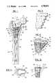
- FIG. 1is an anterior view showing a femoral prosthesis employing a sleeve constructed in accordance with the present invention which has been implanted in a patient's femur.
- the femuris shown in section to illustrate the relationship between the prosthesis and the soft and hard bone portions of the femur.
- FIG. 2is a magnified view of a section through the outside surface of the sleeve of the present invention.
- FIG. 3is a perspective view of the sleeve of the present invention.
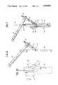
- FIG. 4is an anterior view, partially in section, illustrating the reaming of the patient's femur with a straight reamer.
- FIG. 5is an anterior view, partially in section, illustrating the reaming of the patient's femur with a conical reamer.
- FIG. 6is a perspective view of a suitable tool for cutting a cavity in the patient's femur for the protruding portion of the sleeve of the present invention.
- FIG. 7is an anterior view, partially in section, illustrating the cutting of the patient's femur with the tool of FIG. 6.
- FIG. 8is an anterior view schematically illustrating a family of sleeves having differing protruding portions.
- FIG. 9is an anterior view, partially in section, illustrating the implantation of a sleeve in a patient's femur.
- FIG. 10is a perspective view of a cavity in a patient's femur which has been reamed to receive a sleeve constructed in accordance with the present invention.
- the two center lines shown in this figurecorrespond to the center lines of the conical reamer and cutter shown in FIGS. 5 and 7.
- FIG. 11is a cross-sectional view along lines 11--11 in FIG. 10.
- FIGS. 12 and 13schematically illustrate the criticality of using an elliptical contour in constructing the protruding portion of the sleeve.
- FIG. 14illustrates an alternate embodiment of the invention employing a protruding portion in combination with a straight cylinder.
- FIG. 1a femoral component 10 of an artificial hip joint employing sleeve 13 constructed in accordance with the present invention.
- Sleeve 13includes cone portion 6 centered on the sleeve's longitudinal axis 36 and protruding portion 8 which is offset from and extends away from the longitudinal axis.
- Femoral component 10is implanted in the patient's femur 54 which has an outer shell 56 of hard bone surrounding an inner core 58 of soft bone. Motion of the joint occurs about ball 14.
- the ballis connected to neck 16 which, in turn, is connected to stem 18.
- Stem 18 and sleeve 13mate by means of complementary locking tapers on outside surface 20 of the stem and inside surface 22 of the sleeve.
- the stemis provided with pins 24 which mate with slots 26 in the sleeve so as to prevent the stem from rotating within the sleeve prior to full locking engagement of the tapers.
- the tapers on the sleeve and the stemare nominally sized to provide a gap of approximately 0.060 inches between the bottom of neck 16 and the top of the sleeve.
- pin 24is spaced a nominal 0.060 inches from the bottom of slot 26.
- the outside surface of sleeve 13includes a plurality of terraces 28 having outer and inner edges 30 and 32, respectively (see FIG. 2).
- the vertical spacing between terracesis preferably on the order of between approximately 0.5 mm and approximately 3.0 mm.
- the depth of the terracesis preferably on the order of between approximately 0.2 mm and approximately 1.5 mm.
- the perimeters of outer edges 30lie in planes which are substantially orthogonal to the longitudinal axis 36 of the sleeve.
- the perimeters of outer edges 30include circular portions 34 centered on longitudinal axis 36 and elliptical portions 38 which include vertices 52.
- the radii of circular portions 34decrease as one moves away from the top of the sleeve, the cone angle of these portions, as discussed above, being approximately 6°.
- the distances of vertices 52 from axis 36decrease as one moves away from the top of the sleeve.
- Elliptical portions 38however, all have the same shape in the sense that they are all portions of a common ellipse.
- vertices 52lie on a common line 60 which intersects axis 36 at a predetermined angle.
- the angleis chosen so that the overall shape of the sleeve generally corresponds to the anatomical hard bone shapes encountered in practice. For example, for femoral prostheses, an angle of approximately 32° has been found suitable for achieving the desired matching. Other angles, of course, can be used.
- the angle between line 60 and axis 36is also the angle between shaft 62 and cutter 64 of tool 66 (see FIG. 6).
- the uppermost perimeterincludes a full half of an ellipse extending between ends 68 and 70 of the ellipse's minor axis 40.
- the half ellipseis connected to the circular portion 34 of the perimeter by line segments 42 and 44. These line segments are tangent to the ellipse at points 68 and 70, and thus are parallel to the major axis of the ellipse.
- the major axislies on line 46 which is orthogonal to axis 36.
- the junction between line segments 42 and 44 and circular portion 34are rounded as shown at 48 and 50 to facilitate manufacture.
- shorter line segments 42 and 44are first used and then less than a full half of an ellipse.
- Rounded junctions 48 and 50can also be used with these smaller perimeters.
- the perimeters of outer edges 30are circles with the radii of the circles decreasing as one moves towards the bottom of the sleeve so that outer edges of these perimeters lie on the same cone as portions 34 of the upper perimeters.
- the transition between the upper perimeters and the lower perimetersoccurs at the intersection of line 60 with the cone defined by portions 34 of the upper perimeters. This intersection is shown at 72 in FIG. 3.
- a straight hole for receiving stem 18is formed in the patient's femur 54 using straight reamer 74.
- a conical cavity for receiving cone portion 6 of sleeve 13is formed using conical reamer 76.
- This reamerincludes a pilot shaft 78 for aligning the conical cavity with the straight hole formed by straight reamer 74.
- the conical cavityhas the same cone angle as the circular portions of sleeve 13, e.g., 6°. It is made smaller than the sleeve, e.g., by approximately 0.5 mm, so that the sleeve will fit tightly in the cavity when implanted.
- Tool 66includes pilot shaft 62 for aligning the tool with the straight hole formed by straight reamer 74. It also includes cutter 64 for cutting the cavity and handle 80 for manipulating and stabilizing the tool as the reaming is performed.
- Cutter 64includes fitting 82 for connection to a suitable power source for rotating the bit, e.g., a pneumatic power source.
- tool 66is moved downward (see arrow 84) until the surgeon is satisfied that cutter 64 has reached and prepared a suitable bed or seat for portion 8 of sleeve 13 in the hard bone in the region known as the calcar 86.
- Conical reamer 76 and cutter 64are sized so that the finished cavity formed in the femur generally corresponds to the inner surface of the femur's hard bone. This correspondence can best be seen in FIG. 11. As shown therein, cavity 88 approximates the inner contours of hard bone 56, the maximum separation between the cavity and the hard bone occurring in the region of the femur's greater trochanter 90. Significantly, for physiological and anatomical reasons, it is preferred that the major stress transfers from the sleeve to the femur be in the region of the calcar 86, not the greater trochanter 90, and thus the somewhat greater separation of the cavity, and thus the sleeve, from the patient's hard bone in the region of the greater trochanter is acceptable.
- sets of conical reamers 76 and cutting tools 66are supplied to the surgeon so that femurs of various sizes can be prepared to receive sleeve 13.
- Sets of sleeves of different sizes to match the tools 66are also provided.
- a set of conical reamers having maximum diameters of approximately from 17 mm to 25 mm in 2 mm increments in combination with a corresponding set of cutting tools having cutting diameters of approximately from 8 mm to 18 mm in 2 mm incrementsare suitable for preparing the great majority of femurs encountered in practice.
- a suitable set of sleeves corresponding to these toolscan have maximum diameters of circle portions 34 ranging approximately from 17 mm to 25 mm in 2 mm increments, major axes for elliptical portions 38 approximately from 9 mm to 21 mm in approximately 2.3 mm increments for a 32° angle between line 60 and longitudinal axis 36, minor axes 40 approximately from 8 mm to 18 mm in 2 mm increments, and sleeve heights ranging approximately from 20 mm to 50 mm.
- Other sets of reamers, tools and sleevescan be used and will be readily apparent to persons skilled in the art in view of the present disclosure.
- the diameter of cutter 64 and the angle between cutter 64 and shaft 62determine the major and minor axes of elliptical portions 38 of the perimeters of the outer edges 30 of terraces 28 of sleeve 13.
- the minor axisequals the cutter diameter
- the major axisequals the cutter diameter divided by the cosine of the angle between cutter 64 and shaft 62.
- the major and minor axes of elliptical portion 38are made slightly larger e.g., on the order of 0.5 mm, to ensure a tight fit.
- the calcar in an intact natural boneis highly stressed. Because bone maintains vitality where it is loaded, and atrophies where it is not loaded, it is important to transfer load from sleeve 13 to calcar 86. It is thus critical to use an ellipse for portions 38 of the outer perimeters of terraces 28 in order to achieve a geometric match between the shape of the sleeve and the shape of the cavity formed by tool 66. Specifically, the obvious choice for this contour--a circle--results in a significant mismatch between the prosthesis and the cavity. This criticality is illustrated in FIGS. 12 and 13. As shown therein, prosthesis 92, which employs an elliptical contour, fills cavity 94 in bone 96, while prosthesis 100, which employs a circular contour, leaves a substantial gap 98 between its outer edge and the inside surface of the cavity.
- the surgeonis ready to implant sleeve 13.
- a family of sleevese.g., five sleeves, which differ from one another with regard to the extent to which protruding portion 8 extends away from longitudinal axis 36.
- Such a familyis schematically illustrated in FIG. 8, where the letters A, C and E designate three sleeves having lines 60 progressively further from the sleeve's longitudinal axis.
- the differences between the sleevesis achieved by using longer line segments 42 and 44 for the sleeves having line 60 further from longitudinal axis 36.
- the surgeonis able to compensate for differences in the amount of downward movement of tool 66 needed to reach a sufficient amount of hard bone in the region of calcar 86.
- tool 102includes pilot shaft 104, which is received in the straight hole formed by straight reamer 74, pins 106, which are received in slots 26 in sleeve 13, and flange 108 which contacts the top of the sleeve. Using this tool, sleeve 13 is driven into the prepared cavity.
- the sleeveAs it moves into place, the sleeve, being slightly bigger than the cavity, cuts into the cavity thus generating crushed bone and bone chips at the prosthesis-bone interface. Cutting and crushing also occurs at corners 110 and 112 (see FIG. 11), where rounded corners 48 and 50 of sleeve 13 do not precisely match the prepared cavity. There may also be a small amount of bone projecting into the cavity in the region identified by the number 87 in FIG. 7 as a result of the construction of tool 66. This amount of bone is easily crushed as sleeve 13 is completed seated in the cavity. The generation of bone residue by the cutting and crushing at the foregoing locations is of value since it promotes the bone ingrowth process at the prosthesis-bone interface.
- the outer surface of sleeve 13 between terraces 28is formed with inner edge 32 of each terrace 28 located closer to the sleeve's longitudinal axis than outer edge 30 of the next lower terrace.
- the outer surface of the sleevecan be porous coated using small balls 114 composed of the same metal as that used to form sleeve 13, e.g., a surgically implantable alloy such as a titanium alloy containing 6% aluminum and 4% vanadium or chemically pure titanium (see ASTM Spec. Nos. F136-79 and F67-83).
- a surgically implantable alloysuch as a titanium alloy containing 6% aluminum and 4% vanadium or chemically pure titanium (see ASTM Spec. Nos. F136-79 and F67-83).
- the sleeves of the present inventioncan be formed using computer controlled machine tools.
- a mastercan be prepared using such tools, molds can be prepared from the master, and the finished parts can be cast using the molds.
- Porous coating of the sleevescan be performed using standard techniques such as by heating the coated sleeve to fuse the balls and the sleeve together.
- FIG. 14shows modified sleeve 113 wherein a straight cylinder 116 has been substituted for cone portion 6 of sleeve 13.
- a straight cylinder 116has been substituted for cone portion 6 of sleeve 13.
- elliptical portion 38 of protruding portion 8is terraced, although the remainder of the sleeve could be terraced, if desired, by means of undercutting.
- the inventionhas been illustrated in the context of a femoral prosthesis, it is also applicable to other artificial joints, such as, shoulder and knee joints.
- the sleevecan be formed with two protruding portions extending from opposite sides of the sleeve.
- Other modifications and applicationswill be recognized by persons skilled in the art in view of the present disclosure.
Landscapes
- Health & Medical Sciences (AREA)
- Life Sciences & Earth Sciences (AREA)
- Animal Behavior & Ethology (AREA)
- Veterinary Medicine (AREA)
- Oral & Maxillofacial Surgery (AREA)
- Orthopedic Medicine & Surgery (AREA)
- Public Health (AREA)
- Engineering & Computer Science (AREA)
- Biomedical Technology (AREA)
- Heart & Thoracic Surgery (AREA)
- General Health & Medical Sciences (AREA)
- Surgery (AREA)
- Cardiology (AREA)
- Transplantation (AREA)
- Vascular Medicine (AREA)
- Molecular Biology (AREA)
- Medical Informatics (AREA)
- Nuclear Medicine, Radiotherapy & Molecular Imaging (AREA)
- Dentistry (AREA)
- Prostheses (AREA)
Abstract
Description
1. Field of the Invention
This invention relates to the field of artificial joints and, in particular, to apparatus for affixing such joints to bone.
2. Description of the Prior Art
In PCT publication number WO 85/03426 entitled "Apparatus for Affixing a Prosthesis to Bone," various sleeves for affixing artificial joints to bone are described having the following characteristics: (1) the outer surface of the sleeve is contoured so as to mate with the inner surface of the patient's hard bone; and (2) the outer surface of the sleeve comprises a plurality of spaced, outwardly extending shoulders, the purpose of which is to transfer stresses from the prosthesis to the hard bone in a manner similar to that in which stresses are transferred from soft bone to hard bone.
The present invention is directed to improving the utility of the sleeves disclosed in the foregoing PCT publication. While it is possible to provide sleeves of the type disclosed in the PCT publication which approximate the hard bone contours of individual patients, sleeves of this type do not have a regular geometric shape, and therefore surgeons have found it difficult to prepare patient's bones for receiving such sleeves using standard, or even special, surgical tools for cutting and reaming bone.
In view of the foregoing state of the art, it is an object of this invention to provide sleeves for affixing artificial joints to bone which have outer surfaces which (1) are contoured so that they generally correspond to the inner surfaces of the hard bones of a variety of patients, notwithstanding the anatomical variability from patient to patient, (2) are contoured so that the surgeon can readily and precisely prepare a cavity in the patient's bone for receiving the sleeve, and (3) include a plurality of spaced-apart, outwardly-extending terraces which can cut into the bone, and/or encourage bone ingrowth, and which transfer stresses to the patient's bone in a manner which generally corresponds to the manner in which stresses are transferred from soft bone to hard bone.
More generally, in contrast to the approach of the above-referenced PCT publication, wherein the shape of the patient's hard bone defined the shape of the prosthesis as well as the shape of the cavity to be formed in the patient's bone, the approach of the present invention is to provide a prosthesis shape which can readily be accurately and reproducibly formed in the patient's bone and which in general approximates the shape of the hard bone, and then match the patient's bone to the prosthesis by forming a cavity in the bone which exactly matches the shape of the prosthesis.
To accomplish the foregoing, the invention provides sleeves for implantation in bone having terraced outer surfaces, the perimeters of the outer edges of the terraces having specified shapes so as to satisfy the twin goals of approximating hardbone contours and providing an overall shape for the prosthesis which can be readily cut in the patient's bone by the surgeon.
In particular, the terraces nearest to the motion surface of the joint have a first set of perimeters, while those away from the joint motion surface have a second set of perimeters. All of the perimeters lie in planes which are substantially perpendicular to the longitudinal axis of the sleeve.
The perimeters of the first set are composed of a portion of a circle and a portion of an ellipse. The circle portions are centered on the sleeve's longitudinal axis. The radii of the circles increase as one moves towards the joint motion surface so that the envelope of the circles is a cone. In practice, a total cone angle of, for example, 6° has been found suitable.
Ellipses having the same major and minor axes, i.e., the same shape, are used for each terrace, but the portion of the ellipse used increases from terrace to terrace as one moves towards the joint motion surface until half an ellipse has been used. Thereafter, half an ellipse is used for all terraces closer to the joint motion surface, the halves of ellipses being connected to the circle portions of the perimeters by two lines which are parallel to the ellipse's major axis and tangent to the ellipse at the ends of its minor axis. Optionally, to facilitate the manufacturing process, the junctions between the portion of the ellipse and the portion of the circle or between the two straight lines and the portion of the circle, as the case may be, may be rounded with a portion of a circle of a suitable radius to produce a smooth transition into the circle portion of the perimeter.
The major axes of all of the ellipses lie in a common plane, and all of the axes are orthogonal to the sleeve's longitudinal axis. The portion of the ellipse used for each terrace includes a vertex of the ellipse. The vertices for the different terraces lie along a line which intersects the sleeve's longitudinal axis at a predetermined angle determined by the tool used to ream the patient's bone (see discussion below).
The second set of perimeters are composed of circles centered on the sleeve's longitudinal axis. The radii of the circles increases as one moves towards the joint motion surface so that the circles of the second set of perimeters lie on the same cone as the circle portions of the first set of perimeters.
The transition from the first set of perimeters to the second set of perimeters occurs at the level where the line through the vertices of the ellipses first intersects the cone defined by the circular portions of the first set of perimeters. For some applications, a relatively short sleeve may be desirable, in which case only a first set of perimeters will be used and a transition from the first to the second set of perimeters will not occur.
As discussed below, by using perimeters of the foregoing shapes, the prosthesis can readily be given an overall shape which generally corresponds to the shapes of hard bones encountered in practice. This correspondence can be further improved by supplying the surgeon with families of sleeves (see discussion below).
Moreover, the surgeon can readily prepare the patient's bone for receiving the prosthesis. Specifically, a cavity for receiving the second set of perimeters and the circular portions of the first set of perimeters can be formed in the patient's bone using a conventional conical reamer, and a further cavity, connected to the conical cavity, for receiving the ellipse portions of the first set of perimeters, as well as the connection between those portions and the circular portions, can be formed using the tool shown in FIG. 6 (see discussion below). In general, both cavities are made somewhat smaller than the prosthesis so that the prosthesis fits tightly in the patient's bone when implanted.
The combination of the two cavities produces an overall cavity which in essence perfectly matches the outside shape of the sleeve. This perfect match, in turn, produces a strong, initial, mechanical fixation of the sleeve to the patient's bone and intimate contact between the sleeve and the bone so as to encourage bone ingrowth.
In connection with these latter aspects, in certain embodiments of the invention, the outside surface of the sleeve is undercut between terraces so as to accentuate the ability of the outer edges of the terraces to cut bone. Such cutting occurs as the sleeve is forced into the cavity formed in the patient's bone. The cutting results in the generation of bone chips in the regions between the terraces which further enhances bone ingrowth into these areas.
In connection with other embodiments of the invention, the outside surface of the prosthesis can be covered with a porous coating to further enhance bone ingrowth (see FIG. 2).
The accompanying drawings, which are incorporated in and constitute part of the specification, illustrate the preferred embodiments of the invention, and together with the description, serve to explain the principles of the invention.
FIG. 1 is an anterior view showing a femoral prosthesis employing a sleeve constructed in accordance with the present invention which has been implanted in a patient's femur. The femur is shown in section to illustrate the relationship between the prosthesis and the soft and hard bone portions of the femur.
FIG. 2 is a magnified view of a section through the outside surface of the sleeve of the present invention.
FIG. 3 is a perspective view of the sleeve of the present invention.
FIG. 4 is an anterior view, partially in section, illustrating the reaming of the patient's femur with a straight reamer.
FIG. 5 is an anterior view, partially in section, illustrating the reaming of the patient's femur with a conical reamer.
FIG. 6 is a perspective view of a suitable tool for cutting a cavity in the patient's femur for the protruding portion of the sleeve of the present invention.
FIG. 7 is an anterior view, partially in section, illustrating the cutting of the patient's femur with the tool of FIG. 6.
FIG. 8 is an anterior view schematically illustrating a family of sleeves having differing protruding portions.
FIG. 9 is an anterior view, partially in section, illustrating the implantation of a sleeve in a patient's femur.
FIG. 10 is a perspective view of a cavity in a patient's femur which has been reamed to receive a sleeve constructed in accordance with the present invention. The two center lines shown in this figure correspond to the center lines of the conical reamer and cutter shown in FIGS. 5 and 7.
FIG. 11 is a cross-sectional view along lines 11--11 in FIG. 10.
FIGS. 12 and 13 schematically illustrate the criticality of using an elliptical contour in constructing the protruding portion of the sleeve.
FIG. 14 illustrates an alternate embodiment of the invention employing a protruding portion in combination with a straight cylinder.
With reference now to the drawings, wherein like reference characters designate like or corresponding parts throughout the several views, there is shown in FIG. 1, afemoral component 10 of an artificial hipjoint employing sleeve 13 constructed in accordance with the present invention.Sleeve 13 includescone portion 6 centered on the sleeve'slongitudinal axis 36 and protrudingportion 8 which is offset from and extends away from the longitudinal axis.
The outside surface ofsleeve 13 includes a plurality ofterraces 28 having outer andinner edges outer edges 30 lie in planes which are substantially orthogonal to thelongitudinal axis 36 of the sleeve.
At the upper portion ofsleeve 13, the perimeters ofouter edges 30 includecircular portions 34 centered onlongitudinal axis 36 andelliptical portions 38 which includevertices 52. The radii ofcircular portions 34 decrease as one moves away from the top of the sleeve, the cone angle of these portions, as discussed above, being approximately 6°. Similarly, the distances ofvertices 52 fromaxis 36 decrease as one moves away from the top of the sleeve.Elliptical portions 38, however, all have the same shape in the sense that they are all portions of a common ellipse.
As shown in FIG. 3,vertices 52 lie on acommon line 60 which intersectsaxis 36 at a predetermined angle. The angle is chosen so that the overall shape of the sleeve generally corresponds to the anatomical hard bone shapes encountered in practice. For example, for femoral prostheses, an angle of approximately 32° has been found suitable for achieving the desired matching. Other angles, of course, can be used. As discussed below, the angle betweenline 60 andaxis 36 is also the angle betweenshaft 62 andcutter 64 of tool 66 (see FIG. 6).
As further shown in FIG. 3, the uppermost perimeter includes a full half of an ellipse extending between ends 68 and 70 of the ellipse's minor axis 40. The half ellipse is connected to thecircular portion 34 of the perimeter byline segments points line 46 which is orthogonal toaxis 36. As discussed above, the junction betweenline segments circular portion 34 are rounded as shown at 48 and 50 to facilitate manufacture.
To maintainvertices 52 online 60 for perimeters below the uppermost perimeter,shorter line segments Rounded junctions
At the lower portion ofsleeve 13, the perimeters ofouter edges 30 are circles with the radii of the circles decreasing as one moves towards the bottom of the sleeve so that outer edges of these perimeters lie on the same cone asportions 34 of the upper perimeters. The transition between the upper perimeters and the lower perimeters occurs at the intersection ofline 60 with the cone defined byportions 34 of the upper perimeters. This intersection is shown at 72 in FIG. 3.
Turning now to the process for implantingsleeve 13, as shown in FIG. 4, a straight hole for receivingstem 18 is formed in the patient'sfemur 54 usingstraight reamer 74. Next, as shown in FIG. 5, a conical cavity for receivingcone portion 6 ofsleeve 13 is formed usingconical reamer 76. This reamer includes apilot shaft 78 for aligning the conical cavity with the straight hole formed bystraight reamer 74. The conical cavity has the same cone angle as the circular portions ofsleeve 13, e.g., 6°. It is made smaller than the sleeve, e.g., by approximately 0.5 mm, so that the sleeve will fit tightly in the cavity when implanted.
Next, a cavity for receivingprotruding portion 8 ofsleeve 13 is formed usingtool 66 shown in FIG. 6.Tool 66 includespilot shaft 62 for aligning the tool with the straight hole formed bystraight reamer 74. It also includescutter 64 for cutting the cavity and handle 80 for manipulating and stabilizing the tool as the reaming is performed.Cutter 64 includes fitting 82 for connection to a suitable power source for rotating the bit, e.g., a pneumatic power source. As shown in FIG. 7,tool 66 is moved downward (see arrow 84) until the surgeon is satisfied thatcutter 64 has reached and prepared a suitable bed or seat forportion 8 ofsleeve 13 in the hard bone in the region known as thecalcar 86.
In practice, sets ofconical reamers 76 andcutting tools 66 are supplied to the surgeon so that femurs of various sizes can be prepared to receivesleeve 13. Sets of sleeves of different sizes to match thetools 66 are also provided.
For example, a set of conical reamers having maximum diameters of approximately from 17 mm to 25 mm in 2 mm increments in combination with a corresponding set of cutting tools having cutting diameters of approximately from 8 mm to 18 mm in 2 mm increments are suitable for preparing the great majority of femurs encountered in practice. A suitable set of sleeves corresponding to these tools can have maximum diameters ofcircle portions 34 ranging approximately from 17 mm to 25 mm in 2 mm increments, major axes forelliptical portions 38 approximately from 9 mm to 21 mm in approximately 2.3 mm increments for a 32° angle betweenline 60 andlongitudinal axis 36, minor axes 40 approximately from 8 mm to 18 mm in 2 mm increments, and sleeve heights ranging approximately from 20 mm to 50 mm. Other sets of reamers, tools and sleeves, of course, can be used and will be readily apparent to persons skilled in the art in view of the present disclosure.
The diameter ofcutter 64 and the angle betweencutter 64 andshaft 62 determine the major and minor axes ofelliptical portions 38 of the perimeters of theouter edges 30 ofterraces 28 ofsleeve 13. Specifically, for an exact fit of the protruding portion of the sleeve in the cavity formed bycutter 64, the minor axis equals the cutter diameter, while the major axis equals the cutter diameter divided by the cosine of the angle betweencutter 64 andshaft 62. In practice, the major and minor axes ofelliptical portion 38 are made slightly larger e.g., on the order of 0.5 mm, to ensure a tight fit.
The calcar in an intact natural bone is highly stressed. Because bone maintains vitality where it is loaded, and atrophies where it is not loaded, it is important to transfer load fromsleeve 13 tocalcar 86. It is thus critical to use an ellipse forportions 38 of the outer perimeters ofterraces 28 in order to achieve a geometric match between the shape of the sleeve and the shape of the cavity formed bytool 66. Specifically, the obvious choice for this contour--a circle--results in a significant mismatch between the prosthesis and the cavity. This criticality is illustrated in FIGS. 12 and 13. As shown therein,prosthesis 92, which employs an elliptical contour, fillscavity 94 inbone 96, whileprosthesis 100, which employs a circular contour, leaves asubstantial gap 98 between its outer edge and the inside surface of the cavity.
Returning to the implantation process, once the patient's bone has been reamed withconical reamer 76 and cut withtool 66, the surgeon is ready to implantsleeve 13. In order to further improve the match between the prosthetic sleeve and the cavity in an individual femur, it is preferred to provide the surgeon with a family of sleeves, e.g., five sleeves, which differ from one another with regard to the extent to which protrudingportion 8 extends away fromlongitudinal axis 36. (Note that all of the members of the family have the same basic dimensions corresponding to the size of theconical reamer 76 andcutter 64 used to prepare the cavity, i.e., the same cone angle, the same major and minor axes forelliptical portions 38, the same maximum size forcircular portion 34, and the same overall sleeve height.)
Such a family is schematically illustrated in FIG. 8, where the letters A, C and E designate threesleeves having lines 60 progressively further from the sleeve's longitudinal axis. The differences between the sleeves is achieved by usinglonger line segments sleeves having line 60 further fromlongitudinal axis 36. By selecting among the members of the family, the surgeon is able to compensate for differences in the amount of downward movement oftool 66 needed to reach a sufficient amount of hard bone in the region ofcalcar 86.
Once the proper sleeve for the patient has been chosen, implantation is performed using tool 102 (see FIG. 9). This tool includespilot shaft 104, which is received in the straight hole formed bystraight reamer 74, pins 106, which are received inslots 26 insleeve 13, andflange 108 which contacts the top of the sleeve. Using this tool,sleeve 13 is driven into the prepared cavity.
As it moves into place, the sleeve, being slightly bigger than the cavity, cuts into the cavity thus generating crushed bone and bone chips at the prosthesis-bone interface. Cutting and crushing also occurs atcorners 110 and 112 (see FIG. 11), whererounded corners sleeve 13 do not precisely match the prepared cavity. There may also be a small amount of bone projecting into the cavity in the region identified by thenumber 87 in FIG. 7 as a result of the construction oftool 66. This amount of bone is easily crushed assleeve 13 is completed seated in the cavity. The generation of bone residue by the cutting and crushing at the foregoing locations is of value since it promotes the bone ingrowth process at the prosthesis-bone interface.
To enhance the ability of the sleeve to cut bone, it is preferred to undercut the outer surface ofsleeve 13 betweenterraces 28. Specifically, as shown in FIG. 2, the outer surface is formed withinner edge 32 of eachterrace 28 located closer to the sleeve's longitudinal axis thanouter edge 30 of the next lower terrace.
As also shown in FIG. 2, to further enhance bone ingrowth, the outer surface of the sleeve can be porous coated usingsmall balls 114 composed of the same metal as that used to formsleeve 13, e.g., a surgically implantable alloy such as a titanium alloy containing 6% aluminum and 4% vanadium or chemically pure titanium (see ASTM Spec. Nos. F136-79 and F67-83). By using a single layer of balls (see FIG. 2), the benefits of bone ingrowth can be achieved without sacrificing the benefits resulting from terracing and undercutting the outer surface of the sleeve.
The sleeves of the present invention can be formed using computer controlled machine tools. Alternatively, a master can be prepared using such tools, molds can be prepared from the master, and the finished parts can be cast using the molds. Porous coating of the sleeves can be performed using standard techniques such as by heating the coated sleeve to fuse the balls and the sleeve together.
Although specific embodiments of the invention have been described and illustrated, it is to be understood that modifications can be made without departing from the invention's spirit and scope. For example, FIG. 14 shows modifiedsleeve 113 wherein astraight cylinder 116 has been substituted forcone portion 6 ofsleeve 13. For this sleeve, onlyelliptical portion 38 of protrudingportion 8 is terraced, although the remainder of the sleeve could be terraced, if desired, by means of undercutting.
Along these same lines, although the invention has been illustrated in the context of a femoral prosthesis, it is also applicable to other artificial joints, such as, shoulder and knee joints. In the latter case and for an implantation in the patient's tibia, the sleeve can be formed with two protruding portions extending from opposite sides of the sleeve. Other modifications and applications will be recognized by persons skilled in the art in view of the present disclosure.
Claims (13)
1. A sleeve for affixing a component of an artificial joint to bone, said joint having a joint motion surface, said sleeve comprising a body having a longitudinal axis which defines first and second ends, the first end being towards the joint motion surface and the second end being away from the joint motion surface when the sleeve is implanted in the bone, said body having an outer surface which includes a plurality of terraces, each terrace lying in a plane substantially perpendicular to the longitudinal axis, the perimeter of the outer edge of each terrace located in the region of the first end of the body comprising (a) a portion of a circle centered on the longitudinal axis and (b) a portion of an ellipse whose center is offset from the longitudinal axis, said portion of an ellipse, for each of the terraces, (a) being a portion of a common ellipse so that all of the elliptical portions have the same shape, and (b) including a vertex of the ellipse, the perimeters of the terraces located in said first end region having lengths such that for each pair of adjacent terraces, the perimeter of the outer edge of the terrace closer to the first end is longer than the perimeter of the outer edge of the terrace closer to the second end, at least some of said first end perimeters having an oblong form wherein the elliptical portion of the perimeter is half an ellipse and the perimeter includes two lines which are parallel to the ellipse's major axis, and tangent to the ellipse at the ends of its minor axis and spaced from one another by a distance which is less than the diameter of the circular portion of the perimeter.
2. The sleeve of claim 1 wherein successive adjacent terraces have vertices whose locus is a straight line.
3. The sleeve of claim 2 wherein the perimeter of the outer edge of the terraces in the region of the second end of the body consists of a circle centered on the longitudinal axis.
4. The sleeve of claim 2 wherein the outer surface of the body between some pairs of adjacent terraces is undercut so that the perimeter of the inner edge of the terrace closer to the first end is located closer to the longitudinal axis than the perimeter of the outer edge of the terrace closer to the second end.
5. The sleeve of claim 4 wherein the perimeter of the outer edge of the terraces in the region of the second end of the body consists of a circle centered on the longitudinal axis.
6. The sleeve of claim 5 wherein the joint is an artificial hip joint, the sleeve affixes the femoral component of the joint to the femur, and the perimeters of the outer edges of the terraces generally correspond to the inner surface of the femur's hard bone.
7. The sleeve of claim 1 wherein a portion of the outer surface is coated with essentially a single layer of metal balls.
8. A sleeve for affixing a component of an artificial joint to bone, said joint having a joint motion surface, said sleeve comprising a body having a longitudinal axis which defines first and second ends, the first end being towards the joint motion surface and the second end being away from the joint motion surface when the sleeve is implanted in the bone, said body having: (a) an elongated portion centered on and aligned with the longitudinal axis and extending between the first and second ends; and (b) a protruding portion, offset from the longitudinal axis and extending from the first end towards the second end, the cross-sections of the protruding portion in planes substantially orthogonal to the longitudinal axis each including part of an ellipse, each of said parts of an ellipse being a part of a common ellipse so that all of the parts have the same shape, the outer surface of said protruding portion in the region of said elliptically-shaped parts being terraced, at least some of said protruding portion cross-sections having an oblong form wherein the elliptical part is half an ellipse, said half including only one of the ellipse's foci, and the perimeter of said cross-section includes two lines which are parallel to the ellipse's major axis and tangent to the half ellipse at the ends of its minor axis, the minor axis of the ellipse being smaller than the maximum dimension of the elongated portion at the level of the cross-section in a direction parallel to the minor axis of the ellipse.
9. The sleeve of claim 8 wherein the elongated portion is cylindrically-shaped.
10. The sleeve of claim 8 wherein the elongated portion is cone-shaped.
11. The sleeve of claim 10 wherein the outer surface of the cone-shaped portion is terraced.
12. The sleeve of claim 8 wherein the outer surface of the body between terraces is undercut.
13. The sleeve of claim 8 wherein a portion of the outer surface of the body is coated with essentially a single layer of metal balls.
Priority Applications (7)
| Application Number | Priority Date | Filing Date | Title |
|---|---|---|---|
| US06/907,746US4790852A (en) | 1986-09-15 | 1986-09-15 | Sleeves for affixing artificial joints to bone |
| AT87906520TATE79238T1 (en) | 1986-09-15 | 1987-09-11 | CUFF FOR ATTACHING ARTIFICIAL JOINTS TO BONES. |
| PCT/US1987/002334WO1988001854A1 (en) | 1986-09-15 | 1987-09-11 | Sleeves for affixing artificial joints to bone |
| DE8787906520TDE3781163T2 (en) | 1986-09-15 | 1987-09-11 | CUFF FOR FASTENING ARTIFICIAL JOINTS ON BONES. |
| EP87906520AEP0323978B1 (en) | 1986-09-15 | 1987-09-11 | Sleeves for affixing artificial joints to bone |
| JP62505986AJP2736891B2 (en) | 1986-09-15 | 1987-09-11 | Sleeves for attaching artificial joints to bone |
| CA000546829ACA1290100C (en) | 1986-09-15 | 1987-09-14 | Sleeves for affixing artificial joints to bone |
Applications Claiming Priority (1)
| Application Number | Priority Date | Filing Date | Title |
|---|---|---|---|
| US06/907,746US4790852A (en) | 1986-09-15 | 1986-09-15 | Sleeves for affixing artificial joints to bone |
Publications (1)
| Publication Number | Publication Date |
|---|---|
| US4790852Atrue US4790852A (en) | 1988-12-13 |
Family
ID=25424574
Family Applications (1)
| Application Number | Title | Priority Date | Filing Date |
|---|---|---|---|
| US06/907,746Expired - LifetimeUS4790852A (en) | 1986-09-15 | 1986-09-15 | Sleeves for affixing artificial joints to bone |
Country Status (6)
| Country | Link |
|---|---|
| US (1) | US4790852A (en) |
| EP (1) | EP0323978B1 (en) |
| JP (1) | JP2736891B2 (en) |
| CA (1) | CA1290100C (en) |
| DE (1) | DE3781163T2 (en) |
| WO (1) | WO1988001854A1 (en) |
Cited By (122)
| Publication number | Priority date | Publication date | Assignee | Title |
|---|---|---|---|---|
| US4969904A (en)* | 1988-02-26 | 1990-11-13 | Sulzer Brothers Limited | Bone implant |
| US5002578A (en)* | 1990-05-04 | 1991-03-26 | Venus Corporation | Modular hip stem prosthesis apparatus and method |
| US5035717A (en)* | 1988-05-12 | 1991-07-30 | Brooks Peter J | Insert and method of using same |
| US5041139A (en)* | 1989-04-25 | 1991-08-20 | Branemark Per Ingvar | Anchoring element for supporting a joint mechanism of an ankle, hip or other reconstructed joint |
| US5116379A (en)* | 1988-09-15 | 1992-05-26 | Mclardy Smith Peter D | Prosthesis |
| WO1992019186A1 (en)* | 1991-04-22 | 1992-11-12 | New York University | Femoral endoprosthesis with a lateral support surface |
| US5169401A (en)* | 1991-12-20 | 1992-12-08 | Zimmer, Inc. | Surgical reamer assembly |
| US5263986A (en)* | 1992-02-19 | 1993-11-23 | Joint Medical Products Corporation | Sintered coatings for implantable prostheses |
| US5282866A (en)* | 1992-02-12 | 1994-02-01 | Osteonics Corp. | Prosthetic knee tibial component with axially ribbed keel and apparatus for effecting implant |
| WO1994012124A1 (en)* | 1992-11-30 | 1994-06-09 | Wright Medical Technology, Inc. | Medical instrument and procedure |
| US5342366A (en)* | 1992-02-19 | 1994-08-30 | Biomet, Inc. | Surgical instruments for hip revision |
| US5405389A (en)* | 1992-02-19 | 1995-04-11 | Joint Medical Products Corporation | Sintered coatings for implantable prostheses |
| US5480450A (en)* | 1993-02-11 | 1996-01-02 | The General Hospital Corporation | Method and apparatus for reducing interfacial porosity in a cemented femoral prosthesis |
| WO1996001086A1 (en)* | 1994-07-01 | 1996-01-18 | Ortho Development Corporation | Modular prosthesis |
| US5534005A (en)* | 1994-10-05 | 1996-07-09 | Smith & Nephew Richards, Inc. | Surgical milling system |
| US5540694A (en)* | 1993-06-01 | 1996-07-30 | Joint Medical Products Corporation | Instrument for cutting bone |
| US5549705A (en)* | 1993-10-26 | 1996-08-27 | Howmedica, Inc. | Prosthesis with integral proximal spacer |
| US5591233A (en)* | 1990-06-01 | 1997-01-07 | Depuy Dupont Orthopaedics | Metal/composite hybrid orthopedic implants |
| EP0782842A2 (en) | 1996-01-04 | 1997-07-09 | Joint Medical Products Corporation | Method and apparatus for fitting a prosthesis to a bone |
| US5658349A (en)* | 1991-07-29 | 1997-08-19 | Joint Medical Products Corporation | Prosthetic joint system for bone replacement |
| US5824097A (en)* | 1996-07-23 | 1998-10-20 | Johnson & Johnson Professional, Inc. | Medical fastening system |
| US5879391A (en)* | 1996-09-30 | 1999-03-09 | Johnson & Johnson Professional, Inc. | Modular prosthesis |
| US5908423A (en)* | 1993-05-27 | 1999-06-01 | Howmedica, Inc. | Flexible medullary reaming system |
| WO1999047081A1 (en) | 1998-03-18 | 1999-09-23 | Patrick Michel White | Prosthesis having wedge-shaped body |
| US5957925A (en)* | 1998-05-20 | 1999-09-28 | Bristol-Myers Squibb Co. | Orthopaedic milling instrument |
| US5989259A (en)* | 1998-08-25 | 1999-11-23 | Johnson & Johnson Professional, Inc. | Femoral calcar stop for use with femoral stem inserter |
| EP0888098A4 (en)* | 1996-02-21 | 2000-03-01 | Smith & Nephew Inc | Trial wedges with magnetic attachments |
| US6063122A (en)* | 1998-06-22 | 2000-05-16 | Johnson & Johnson Professional, Inc. | Jack screw adapter for joint prosthesis |
| EP1004283A2 (en) | 1998-11-23 | 2000-05-31 | Johnson & Johnson Professional, Inc. | Modular stem and sleeve prosthesis |
| US6071311A (en)* | 1998-08-14 | 2000-06-06 | Johnson & Johnson Professional, Inc. | Cylindrical box femoral stem |
| US6120507A (en)* | 1999-01-29 | 2000-09-19 | Bristol-Myers Squibb Company | Instrument and method for seating prosthesis |
| US6162226A (en)* | 1998-09-25 | 2000-12-19 | Depuy Orthopaedics, Inc. | Long bone reamer with depth stop indicator |
| US6171342B1 (en) | 1996-07-23 | 2001-01-09 | Depuy Orthopaedics, Inc. | Medical fastening system |
| US6319286B1 (en) | 2000-03-13 | 2001-11-20 | Exactech, Inc | Modular hip prosthesis |
| EP1013241A3 (en)* | 1998-12-22 | 2002-03-06 | JOHNSON & JOHNSON PROFESSIONAL Inc. | Proximal femoral sleeve for a revision hip prosthesis |
| US20020042655A1 (en)* | 2000-09-20 | 2002-04-11 | Hayes Daniel E. E. | Modular prosthetic component with improved body shape |
| US6371991B1 (en) | 1996-12-23 | 2002-04-16 | Depuy Orthopaedics, Inc. | Alignment guide for fluted prosthetic stems |
| EP1216668A2 (en) | 2000-12-14 | 2002-06-26 | Depuy Orthopaedics, Inc. | Prosthesis with feature aligned to trabeculae |
| US6497728B2 (en)* | 2000-02-16 | 2002-12-24 | Korea Advanced Institute Of Science And Technology | Metal jacket for a cementless artificial joint stem and artificial joint having the jacket |
| US6527807B1 (en) | 1998-09-09 | 2003-03-04 | Johnson & Johnson Professional, Inc. | Femoral stem attachment for a modular knee prosthesis |
| US20030065397A1 (en)* | 2001-08-27 | 2003-04-03 | Hanssen Arlen D. | Prosthetic implant support structure |
| US20030187449A1 (en)* | 2002-03-29 | 2003-10-02 | Mccleary Larry G. | Medical instrument for milling a curved path in bone and procedure |
| US6656226B2 (en)* | 2000-02-16 | 2003-12-02 | Korea Advanced Institute Of Science And Technology | Plastic jacket for a cementless artificial joint stem and artificial joint having the jacket |
| US20030236522A1 (en)* | 2002-06-21 | 2003-12-25 | Jack Long | Prosthesis cavity cutting guide, cutting tool and method |
| US20030236521A1 (en)* | 2002-06-21 | 2003-12-25 | Scott Brown | Prosthesis cutting guide, cutting tool and method |
| US6669728B2 (en) | 2000-07-20 | 2003-12-30 | Depuy Products, Inc. | Modular connection for orthopedic component |
| US6702854B1 (en) | 1999-06-01 | 2004-03-09 | Apex Surgical, Llc | Implantable joint prosthesis |
| US20040049285A1 (en)* | 2002-09-09 | 2004-03-11 | Brian Haas | Duo-fixation prosthetic joints |
| US20040162619A1 (en)* | 2001-08-27 | 2004-08-19 | Zimmer Technology, Inc. | Tibial augments for use with knee joint prostheses, method of implanting the tibial augment, and associated tools |
| US20040199259A1 (en)* | 2003-03-10 | 2004-10-07 | Benoist Girard Sas | Femoral prosthesis |
| US20050010232A1 (en)* | 2002-04-11 | 2005-01-13 | Crofford Theodre W. | Method of implanting a femoral neck fixation prosthesis |
| US20050043811A1 (en)* | 2003-08-22 | 2005-02-24 | Doubler Robert L. | Welded hip prosthesis |
| US20050288676A1 (en)* | 2004-06-29 | 2005-12-29 | Barry Schnieders | Minimally invasive bone broach |
| US20060167560A1 (en)* | 2004-12-17 | 2006-07-27 | Heck Robert K | Modular implant system and method with diaphyseal implant and adapter |
| US20060167555A1 (en)* | 2004-12-17 | 2006-07-27 | Heck Robert K | Modular diaphyseal and collar implant |
| US20060167554A1 (en)* | 2004-12-17 | 2006-07-27 | Heck Robert K | Modular implant system and method with diaphyseal implant |
| US20070043447A1 (en)* | 2003-10-09 | 2007-02-22 | Cheal Edward J | Tapered joint prosthesis |
| US20070050041A1 (en)* | 2005-08-30 | 2007-03-01 | Dietz Terry L | Orthopaedic implant stem component, joint component, and associated kit |
| US20070118229A1 (en)* | 2004-05-28 | 2007-05-24 | Smith & Nephew, Inc. | Fluted sleeve hip prosthesis for modular stem |
| US7323013B2 (en) | 1998-04-14 | 2008-01-29 | Encore Medical Asset Corporation | Differential porosity prosthetic hip system |
| US7374576B1 (en) | 2004-01-22 | 2008-05-20 | Medicinelodge, Inc | Polyaxial orthopedic fastening apparatus with independent locking modes |
| US20080140211A1 (en)* | 2006-09-01 | 2008-06-12 | Doubler Robert L | Modular shoulder prosthesis with load bearing surface |
| US20080140210A1 (en)* | 2006-09-01 | 2008-06-12 | Doubler Robert L | Modular shoulder prosthesis |
| US20080161812A1 (en)* | 2006-09-29 | 2008-07-03 | Depuy Products, Inc. | Calcar planar |
| US7445639B2 (en) | 2001-02-23 | 2008-11-04 | Biomet Manufacturing Corp. | Knee joint prosthesis |
| US7497874B1 (en) | 2001-02-23 | 2009-03-03 | Biomet Manufacturing Corp. | Knee joint prosthesis |
| US20090270860A1 (en)* | 2004-05-28 | 2009-10-29 | Smith & Nephew, Inc | Fluted intramedullary stem |
| US20100057212A1 (en)* | 2008-06-03 | 2010-03-04 | Depuy Products, Inc. | Porous Titanium Tibial Sleeves and Their Use in Revision Knee Surgery |
| EP2181673A1 (en) | 2008-10-31 | 2010-05-05 | DePuy Products, Inc. | Knee prosthesis kit with a winged metaphyseal sleeve |
| US20100222891A1 (en)* | 2003-11-18 | 2010-09-02 | Depuy Products, Inc. | Modular implant system with fully porous coated sleeve |
| US7842093B2 (en) | 2006-07-18 | 2010-11-30 | Biomet Manufacturing Corp. | Method and apparatus for a knee implant |
| US7914584B2 (en) | 2004-10-21 | 2011-03-29 | Biomet Manufacturing Corp. | Prosthesis system with trunnion and removably coupled head |
| US7935118B2 (en) | 2002-06-21 | 2011-05-03 | Depuy Products, Inc. | Prosthesis removal cutting guide, cutting tool and method |
| US20110196503A1 (en)* | 2008-09-26 | 2011-08-11 | Merete Medical Gmbh | Modular Joint Prosthesis |
| US7998217B1 (en) | 2005-02-02 | 2011-08-16 | Biomet Manufacturing Corp. | Modular offset stem implants |
| US20110208315A1 (en)* | 2008-09-02 | 2011-08-25 | Merete Medical Gmbh | Knee Arthrodesis Implant |
| US8157869B2 (en) | 2007-01-10 | 2012-04-17 | Biomet Manufacturing Corp. | Knee joint prosthesis system and method for implantation |
| US8163028B2 (en) | 2007-01-10 | 2012-04-24 | Biomet Manufacturing Corp. | Knee joint prosthesis system and method for implantation |
| US8187280B2 (en) | 2007-10-10 | 2012-05-29 | Biomet Manufacturing Corp. | Knee joint prosthesis system and method for implantation |
| US20120156646A1 (en)* | 2010-12-21 | 2012-06-21 | Zimmer Dental, Inc. | Implant with porous sleeve including anti-rotation features |
| US8221432B2 (en) | 2010-03-05 | 2012-07-17 | Biomet Manufacturing Corp. | Method and apparatus for implanting a modular femoral hip |
| US8328873B2 (en) | 2007-01-10 | 2012-12-11 | Biomet Manufacturing Corp. | Knee joint prosthesis system and method for implantation |
| US8333807B2 (en) | 2010-03-05 | 2012-12-18 | Biomet Manufacturing Corp. | Method and apparatus for trialing and implanting a modular femoral hip |
| US8419743B2 (en) | 2010-03-05 | 2013-04-16 | Biomet Manufacturing Corp. | Assembly tool for modular implants and associated method |
| US8424183B2 (en) | 2008-06-03 | 2013-04-23 | DePuy Synthes Products, LLC | Porous titanium femoral sleeves and their use in revision knee surgery |
| US8460393B2 (en) | 2010-03-05 | 2013-06-11 | Biomet Manufacturing Corp. | Modular lateral hip augments |
| USD684693S1 (en) | 2002-08-22 | 2013-06-18 | Zimmer, Inc. | Prosthetic implant support structure |
| US8529569B2 (en) | 2010-03-05 | 2013-09-10 | Biomet Manufacturing, Llc | Method and apparatus for preparing a proximal femur |
| US8562616B2 (en) | 2007-10-10 | 2013-10-22 | Biomet Manufacturing, Llc | Knee joint prosthesis system and method for implantation |
| EP2664301A1 (en) | 2012-05-14 | 2013-11-20 | DePuy (Ireland) | Prosthesis kit with finned sleeve |
| US8679130B2 (en) | 2010-03-05 | 2014-03-25 | Biomet Manufacturing, Llc | Guide assembly for lateral implants and associated methods |
| EP2710969A1 (en) | 2012-09-20 | 2014-03-26 | DePuy (Ireland) | Orthopaedic surgical instrument system |
| EP2710979A1 (en) | 2012-09-20 | 2014-03-26 | DePuy (Ireland) | Modular knee prosthesis system |
| EP2710981A1 (en) | 2012-09-20 | 2014-03-26 | DePuy (Ireland) | Orthopaedic knee prosthesis system |
| EP2710980A1 (en) | 2012-09-20 | 2014-03-26 | DePuy (Ireland) | Modular knee prosthesis system |
| US20140277528A1 (en)* | 2013-03-15 | 2014-09-18 | Angela Black Mines | Knee augment |
| US20140277567A1 (en)* | 2013-03-13 | 2014-09-18 | Howmedica Osteonics Corp. | Void filling joint prosthesis and associated instruments |
| US8900317B2 (en) | 2011-05-20 | 2014-12-02 | Zimmer, Inc. | Stabilizing prosthesis support structure |
| US8932364B2 (en) | 2010-07-14 | 2015-01-13 | Howmedica Osteonics Corp. | Prosthetic knee void filers with splined fixation |
| US8956394B1 (en) | 2014-08-05 | 2015-02-17 | Woven Orthopedic Technologies, Llc | Woven retention devices, systems and methods |
| US8961612B2 (en) | 2012-08-30 | 2015-02-24 | Biomet Manufacturing, Llc | Knee component having orbital interface boss |
| US9011444B2 (en) | 2011-12-09 | 2015-04-21 | Howmedica Osteonics Corp. | Surgical reaming instrument for shaping a bone cavity |
| US9044326B2 (en) | 2001-08-27 | 2015-06-02 | Zimmer, Inc. | Femoral augments for use with knee joint prosthesis |
| US9149282B2 (en) | 2011-12-30 | 2015-10-06 | Howmedica Osteonics Corp. | Systems and methods for preparing bone voids to receive a prosthesis |
| USD740427S1 (en) | 2014-10-17 | 2015-10-06 | Woven Orthopedic Technologies, Llc | Orthopedic woven retention device |
| US20150342745A1 (en)* | 2014-06-02 | 2015-12-03 | Stryker European Holdings I, Llc | Metacarpal rod anchor for a trapezometacarpal prosthesis |
| CN101744675B (en)* | 2008-10-31 | 2016-12-14 | 德普伊产品公司 | There is the knee prosthesis kit of winged sleeve pipe and milling guide |
| US9585695B2 (en) | 2013-03-15 | 2017-03-07 | Woven Orthopedic Technologies, Llc | Surgical screw hole liner devices and related methods |
| US9907593B2 (en) | 2014-08-05 | 2018-03-06 | Woven Orthopedic Technologies, Llc | Woven retention devices, systems and methods |
| US9943351B2 (en) | 2014-09-16 | 2018-04-17 | Woven Orthopedic Technologies, Llc | Woven retention devices, systems, packaging, and related methods |
| US10299929B2 (en) | 2015-01-12 | 2019-05-28 | Howmedica Osteonics Corp. | Bone void forming apparatus |
| US10363051B2 (en) | 2015-06-30 | 2019-07-30 | DePuy Synthes Products, Inc. | Method and orthopaedic surgical instrument system for surgically preparing a patient's bone |
| US10555758B2 (en) | 2015-08-05 | 2020-02-11 | Woven Orthopedic Technologies, Llc | Tapping devices, systems and methods for use in bone tissue |
| USD901012S1 (en) | 2019-08-12 | 2020-11-03 | Ortho Development Corporation | Porous implant |
| USD901014S1 (en) | 2019-08-12 | 2020-11-03 | Ortho Development Corporation | Porous implant |
| USD901013S1 (en) | 2019-08-12 | 2020-11-03 | Ortho Development Corporation | Porous implant |
| US11141276B2 (en) | 2017-01-20 | 2021-10-12 | Biomet Manufacturing, Llc | Modular augment component |
| US11395681B2 (en) | 2016-12-09 | 2022-07-26 | Woven Orthopedic Technologies, Llc | Retention devices, lattices and related systems and methods |
| US11498124B1 (en) | 2019-11-25 | 2022-11-15 | Ortho Development Corporation | Method for sintering porous structures from powder using additive manufacturing |
| US11565021B1 (en) | 2019-08-12 | 2023-01-31 | Ortho Development Corporation | Composite structure porous implant for replacing bone stock |
| US12115084B2 (en) | 2021-12-21 | 2024-10-15 | Depuy Ireland Unlimited Company | Method of installing a knee cone augment in an orthopaedic surgical procedure |
| US12434302B2 (en) | 2019-11-25 | 2025-10-07 | Ortho Development Corporation | Method for manufacturing porous structures using additive manufacturing |
Families Citing this family (15)
| Publication number | Priority date | Publication date | Assignee | Title |
|---|---|---|---|---|
| US4827919A (en)* | 1986-10-27 | 1989-05-09 | Pfizer Hospital Products Group, Inc. | Femoral spacer |
| JPS63240857A (en)* | 1987-03-30 | 1988-10-06 | 京セラ株式会社 | bone prosthesis components |
| AU617798B2 (en)* | 1988-05-12 | 1991-12-05 | Peter John Brooks | Femoral insert and method of using same |
| US5062854A (en)* | 1988-10-07 | 1991-11-05 | Pfizer Hospital Products Group | Prosthetic device and method of implantation |
| US5002580A (en)* | 1988-10-07 | 1991-03-26 | Pfizer Hospital Products Group, Inc. | Prosthetic device and method of implantation |
| US5147408A (en)* | 1988-10-07 | 1992-09-15 | Pfizer Hospital Products Group, Inc. | Prosthetic device and method of implantation |
| FR2644690B1 (en)* | 1989-03-21 | 1992-09-18 | Matco | FEMALE PROSTHESIS WITH SCREWED AND THREADED DIAPHRAGM ANCHORING SYSTEM |
| AU633071B2 (en)* | 1989-04-25 | 1993-01-21 | Per-Ingvar Branemark | Anchoring element for supporting a joint mechanism of an ankle, or other reconstructed joint |
| DE69410992T2 (en)* | 1993-02-09 | 1998-10-22 | Howmedica | MODULAR HIP PROSTHESIS |
| US5607431A (en)* | 1995-02-09 | 1997-03-04 | Howmedica Inc. | Prosthetic hip implantation method and apparatus |
| US5976139A (en) | 1996-07-17 | 1999-11-02 | Bramlet; Dale G. | Surgical fastener assembly |
| US5984970A (en)* | 1996-03-13 | 1999-11-16 | Bramlet; Dale G. | Arthroplasty joint assembly |
| CA2225375A1 (en)* | 1996-12-23 | 1998-06-23 | Mark Manasas | Alignment guide for insertion of fluted or keyed orthopedic components |
| DE102004008138B8 (en)* | 2004-02-19 | 2009-04-23 | Mathys Ag Bettlach | Femoral component for a hip joint endoprosthesis |
| US7806936B2 (en)* | 2006-10-19 | 2010-10-05 | Depuy Products, Inc. | Bowed femoral sleeve |
Citations (3)
| Publication number | Priority date | Publication date | Assignee | Title |
|---|---|---|---|---|
| US3894297A (en)* | 1973-08-31 | 1975-07-15 | Oscobal Ag Chirurgische Instr | Hip joint prosthesis |
| WO1985003426A1 (en)* | 1984-02-09 | 1985-08-15 | Joint Medical Products Corporation | Apparatus for affixing a prosthesis to bone |
| US4670015A (en)* | 1984-04-13 | 1987-06-02 | Finsbury (Instruments) Limited | Hip implant |
Family Cites Families (1)
| Publication number | Priority date | Publication date | Assignee | Title |
|---|---|---|---|---|
| CA1227002A (en)* | 1982-02-18 | 1987-09-22 | Robert V. Kenna | Bone prosthesis with porous coating |
- 1986
- 1986-09-15USUS06/907,746patent/US4790852A/ennot_activeExpired - Lifetime
- 1987
- 1987-09-11DEDE8787906520Tpatent/DE3781163T2/ennot_activeExpired - Lifetime
- 1987-09-11WOPCT/US1987/002334patent/WO1988001854A1/enactiveIP Right Grant
- 1987-09-11EPEP87906520Apatent/EP0323978B1/ennot_activeExpired - Lifetime
- 1987-09-11JPJP62505986Apatent/JP2736891B2/ennot_activeExpired - Lifetime
- 1987-09-14CACA000546829Apatent/CA1290100C/ennot_activeExpired - Lifetime
Patent Citations (3)
| Publication number | Priority date | Publication date | Assignee | Title |
|---|---|---|---|---|
| US3894297A (en)* | 1973-08-31 | 1975-07-15 | Oscobal Ag Chirurgische Instr | Hip joint prosthesis |
| WO1985003426A1 (en)* | 1984-02-09 | 1985-08-15 | Joint Medical Products Corporation | Apparatus for affixing a prosthesis to bone |
| US4670015A (en)* | 1984-04-13 | 1987-06-02 | Finsbury (Instruments) Limited | Hip implant |
Non-Patent Citations (5)
| Title |
|---|
| Freeman et al., in The Young Patient with Degenerative Hip Disease, Sevastik J. Goldie I (ed.), Stockholm, Sweden, 1986, pp. 281 292.* |
| Freeman et al., in The Young Patient with Degenerative Hip Disease, Sevastik J. Goldie I (ed.), Stockholm, Sweden, 1986, pp. 281-292. |
| Freeman, M. A. R., "Why Resect the Neck?", The Journal of Bone and Joint Surgery, vol. 68-B, No. 3, May 1986, pp. 346-349. |
| Freeman, M. A. R., Why Resect the Neck , The Journal of Bone and Joint Surgery, vol. 68 B, No. 3, May 1986, pp. 346 349.* |
| The Freeman Total Hip System, Corin Medical Limited, Gloucestershire, England, 1985.* |
Cited By (262)
| Publication number | Priority date | Publication date | Assignee | Title |
|---|---|---|---|---|
| US4969904A (en)* | 1988-02-26 | 1990-11-13 | Sulzer Brothers Limited | Bone implant |
| US5035717A (en)* | 1988-05-12 | 1991-07-30 | Brooks Peter J | Insert and method of using same |
| US5116379A (en)* | 1988-09-15 | 1992-05-26 | Mclardy Smith Peter D | Prosthesis |
| US5041139A (en)* | 1989-04-25 | 1991-08-20 | Branemark Per Ingvar | Anchoring element for supporting a joint mechanism of an ankle, hip or other reconstructed joint |
| US5002578A (en)* | 1990-05-04 | 1991-03-26 | Venus Corporation | Modular hip stem prosthesis apparatus and method |
| US5591233A (en)* | 1990-06-01 | 1997-01-07 | Depuy Dupont Orthopaedics | Metal/composite hybrid orthopedic implants |
| WO1992019186A1 (en)* | 1991-04-22 | 1992-11-12 | New York University | Femoral endoprosthesis with a lateral support surface |
| US5211666A (en)* | 1991-04-22 | 1993-05-18 | New York University | Hip joint femoral component endoprosthesis with a lateral load-transferring support surface |
| US5658349A (en)* | 1991-07-29 | 1997-08-19 | Joint Medical Products Corporation | Prosthetic joint system for bone replacement |
| US5169401A (en)* | 1991-12-20 | 1992-12-08 | Zimmer, Inc. | Surgical reamer assembly |
| US5282866A (en)* | 1992-02-12 | 1994-02-01 | Osteonics Corp. | Prosthetic knee tibial component with axially ribbed keel and apparatus for effecting implant |
| WO1993016656A3 (en)* | 1992-02-19 | 1994-06-23 | Joint Medical Products Corp | Sintered coatings for implantable prostheses |
| US5342366A (en)* | 1992-02-19 | 1994-08-30 | Biomet, Inc. | Surgical instruments for hip revision |
| US5358533A (en)* | 1992-02-19 | 1994-10-25 | Joint Medical Products Corporation | Sintered coatings for implantable prostheses |
| US5405389A (en)* | 1992-02-19 | 1995-04-11 | Joint Medical Products Corporation | Sintered coatings for implantable prostheses |
| US5263986A (en)* | 1992-02-19 | 1993-11-23 | Joint Medical Products Corporation | Sintered coatings for implantable prostheses |
| US5342363A (en)* | 1992-11-30 | 1994-08-30 | Wright Medical Technology, Inc. | Medical instrument and procedure |
| WO1994012124A1 (en)* | 1992-11-30 | 1994-06-09 | Wright Medical Technology, Inc. | Medical instrument and procedure |
| US5480450A (en)* | 1993-02-11 | 1996-01-02 | The General Hospital Corporation | Method and apparatus for reducing interfacial porosity in a cemented femoral prosthesis |
| US5908423A (en)* | 1993-05-27 | 1999-06-01 | Howmedica, Inc. | Flexible medullary reaming system |
| US5540694A (en)* | 1993-06-01 | 1996-07-30 | Joint Medical Products Corporation | Instrument for cutting bone |
| US5549705A (en)* | 1993-10-26 | 1996-08-27 | Howmedica, Inc. | Prosthesis with integral proximal spacer |
| WO1996001086A1 (en)* | 1994-07-01 | 1996-01-18 | Ortho Development Corporation | Modular prosthesis |
| US5653765A (en)* | 1994-07-01 | 1997-08-05 | Ortho Development Corporation | Modular prosthesis |
| AU695603B2 (en)* | 1994-07-01 | 1998-08-20 | Ortho Development Corporation | Modular prosthesis |
| US5534005A (en)* | 1994-10-05 | 1996-07-09 | Smith & Nephew Richards, Inc. | Surgical milling system |
| EP0782842A3 (en)* | 1996-01-04 | 1998-06-10 | Joint Medical Products Corporation | Method and apparatus for fitting a prosthesis to a bone |
| EP0782842A2 (en) | 1996-01-04 | 1997-07-09 | Joint Medical Products Corporation | Method and apparatus for fitting a prosthesis to a bone |
| US6702822B1 (en)* | 1996-01-04 | 2004-03-09 | Joint Medical Products Corporation | Method and apparatus for fitting a prosthesis to a bone |
| US6152963A (en)* | 1996-01-04 | 2000-11-28 | Joint Medical Products Corporation | Method and apparatus for fitting a prosthesis to a bone |
| EP0888098A4 (en)* | 1996-02-21 | 2000-03-01 | Smith & Nephew Inc | Trial wedges with magnetic attachments |
| US5824097A (en)* | 1996-07-23 | 1998-10-20 | Johnson & Johnson Professional, Inc. | Medical fastening system |
| US6171342B1 (en) | 1996-07-23 | 2001-01-09 | Depuy Orthopaedics, Inc. | Medical fastening system |
| US5879391A (en)* | 1996-09-30 | 1999-03-09 | Johnson & Johnson Professional, Inc. | Modular prosthesis |
| US6371991B1 (en) | 1996-12-23 | 2002-04-16 | Depuy Orthopaedics, Inc. | Alignment guide for fluted prosthetic stems |
| WO1999047081A1 (en) | 1998-03-18 | 1999-09-23 | Patrick Michel White | Prosthesis having wedge-shaped body |
| US6428578B2 (en) | 1998-03-18 | 2002-08-06 | Sct Incorporated | Modular prosthesis and connector therefor |
| US7323013B2 (en) | 1998-04-14 | 2008-01-29 | Encore Medical Asset Corporation | Differential porosity prosthetic hip system |
| US5957925A (en)* | 1998-05-20 | 1999-09-28 | Bristol-Myers Squibb Co. | Orthopaedic milling instrument |
| US6063122A (en)* | 1998-06-22 | 2000-05-16 | Johnson & Johnson Professional, Inc. | Jack screw adapter for joint prosthesis |
| US6071311A (en)* | 1998-08-14 | 2000-06-06 | Johnson & Johnson Professional, Inc. | Cylindrical box femoral stem |
| US5989259A (en)* | 1998-08-25 | 1999-11-23 | Johnson & Johnson Professional, Inc. | Femoral calcar stop for use with femoral stem inserter |
| US6527807B1 (en) | 1998-09-09 | 2003-03-04 | Johnson & Johnson Professional, Inc. | Femoral stem attachment for a modular knee prosthesis |
| US6162226A (en)* | 1998-09-25 | 2000-12-19 | Depuy Orthopaedics, Inc. | Long bone reamer with depth stop indicator |
| US6264699B1 (en) | 1998-11-23 | 2001-07-24 | Depuy Orthopaedics, Inc. | Modular stem and sleeve prosthesis |
| EP1004283A3 (en)* | 1998-11-23 | 2002-03-27 | Johnson & Johnson Professional, Inc. | Modular stem and sleeve prosthesis |
| EP1004283A2 (en) | 1998-11-23 | 2000-05-31 | Johnson & Johnson Professional, Inc. | Modular stem and sleeve prosthesis |
| EP1013241A3 (en)* | 1998-12-22 | 2002-03-06 | JOHNSON & JOHNSON PROFESSIONAL Inc. | Proximal femoral sleeve for a revision hip prosthesis |
| US6120507A (en)* | 1999-01-29 | 2000-09-19 | Bristol-Myers Squibb Company | Instrument and method for seating prosthesis |
| US7044975B2 (en) | 1999-06-01 | 2006-05-16 | Apex Surgical, Llc | Joint prostheses and components thereof |
| US6702854B1 (en) | 1999-06-01 | 2004-03-09 | Apex Surgical, Llc | Implantable joint prosthesis |
| US6497728B2 (en)* | 2000-02-16 | 2002-12-24 | Korea Advanced Institute Of Science And Technology | Metal jacket for a cementless artificial joint stem and artificial joint having the jacket |
| US6656226B2 (en)* | 2000-02-16 | 2003-12-02 | Korea Advanced Institute Of Science And Technology | Plastic jacket for a cementless artificial joint stem and artificial joint having the jacket |
| US6319286B1 (en) | 2000-03-13 | 2001-11-20 | Exactech, Inc | Modular hip prosthesis |
| US7537408B2 (en) | 2000-07-20 | 2009-05-26 | Depuy Products, Inc. | Modular connection for orthopedic component |
| US20070093908A1 (en)* | 2000-07-20 | 2007-04-26 | Despres Alfred S Iii | Modular femoral stem component for a hip joint prosthesis |
| US6669728B2 (en) | 2000-07-20 | 2003-12-30 | Depuy Products, Inc. | Modular connection for orthopedic component |
| US6682568B2 (en) | 2000-07-20 | 2004-01-27 | Depuy Products, Inc. | Modular femoral stem component for a hip joint prosthesis |
| US8303668B2 (en) | 2000-07-20 | 2012-11-06 | Depuy Products, Inc. | Modular femoral stem component for a hip joint prosthesis |
| US7125193B2 (en) | 2000-07-20 | 2006-10-24 | Depuy Products, Inc. | Modular connection for orthopedic component |
| US7097664B2 (en)* | 2000-07-20 | 2006-08-29 | Depuy Products, Inc. | Modular femoral stem component for a hip joint prosthesis |
| US20040243248A1 (en)* | 2000-07-20 | 2004-12-02 | Despres Alfred S. | Modular femoral stem component for a hip joint prosthesis |
| US20050089365A1 (en)* | 2000-07-20 | 2005-04-28 | Despres Alfred S.Iii | Modular connection for orthopedic component |
| US9161840B2 (en) | 2000-09-20 | 2015-10-20 | Consensus Orthopedics, Inc. | Modular prosthetic component with improved body shape |
| US6843806B2 (en) | 2000-09-20 | 2005-01-18 | Daniel E. E. Hayes, Jr. | Modular prosthetic component with improved body shape |
| US20020042655A1 (en)* | 2000-09-20 | 2002-04-11 | Hayes Daniel E. E. | Modular prosthetic component with improved body shape |
| US20050283254A1 (en)* | 2000-09-20 | 2005-12-22 | Hayes Daniel E E Jr | Modular prosthetic component with improved body shape |
| US6949124B2 (en) | 2000-12-14 | 2005-09-27 | Depuy Products, Inc. | Prosthesis with feature aligned to trabeculae |
| EP1216668A2 (en) | 2000-12-14 | 2002-06-26 | Depuy Orthopaedics, Inc. | Prosthesis with feature aligned to trabeculae |
| US6652591B2 (en) | 2000-12-14 | 2003-11-25 | Depuy Orthopaedics, Inc. | Prosthesis with feature aligned to trabeculae |
| US7214246B2 (en) | 2000-12-14 | 2007-05-08 | Depuy Orthopaedics, Inc. | Prosthesis with feature aligned to trabeculae |
| US20040059427A1 (en)* | 2000-12-14 | 2004-03-25 | Serbousek Jon C. | Prosthesis with feature aligned to trabeculae |
| US7445639B2 (en) | 2001-02-23 | 2008-11-04 | Biomet Manufacturing Corp. | Knee joint prosthesis |
| US7497874B1 (en) | 2001-02-23 | 2009-03-03 | Biomet Manufacturing Corp. | Knee joint prosthesis |
| US9044326B2 (en) | 2001-08-27 | 2015-06-02 | Zimmer, Inc. | Femoral augments for use with knee joint prosthesis |
| US10092404B2 (en) | 2001-08-27 | 2018-10-09 | Zimmer, Inc. | Prosthetic implant support structure |
| US20030065397A1 (en)* | 2001-08-27 | 2003-04-03 | Hanssen Arlen D. | Prosthetic implant support structure |
| US9265614B2 (en) | 2001-08-27 | 2016-02-23 | Zimmer, Inc. | Method of implanting the tibial augment |
| US20040162619A1 (en)* | 2001-08-27 | 2004-08-19 | Zimmer Technology, Inc. | Tibial augments for use with knee joint prostheses, method of implanting the tibial augment, and associated tools |
| US9539096B2 (en)* | 2001-08-27 | 2017-01-10 | Zimmer, Inc. | Methods for supporting a prosthetic implant in a patient |
| US9713532B2 (en) | 2001-08-27 | 2017-07-25 | Zimmer, Inc. | Method for augmenting femoral components of knee joint prosthesis |
| US9907664B2 (en) | 2001-08-27 | 2018-03-06 | Zimmer, Inc. | Methods for augmenting a tibial component of a knee joint prosthesis |
| US8728168B2 (en) | 2001-08-27 | 2014-05-20 | Zimmer, Inc. | Prosthetic implant support structure |
| US8506645B2 (en) | 2001-08-27 | 2013-08-13 | Zimmer, Inc. | Tibial augments for use with knee joint prostheses |
| US10085841B2 (en) | 2001-08-27 | 2018-10-02 | Zimmer, Inc. | Femoral implant systems |
| US10893947B2 (en) | 2001-08-27 | 2021-01-19 | Zimmer, Inc. | Femoral augments for use with knee joint prosthesis |
| US10098743B2 (en) | 2001-08-27 | 2018-10-16 | Zimmer, Inc. | Prosthetic implant support structure |
| US20100145452A1 (en)* | 2001-08-27 | 2010-06-10 | Zimmer, Inc. | Prosthetic implant support structure |
| US10201426B2 (en) | 2001-08-27 | 2019-02-12 | Zimmer, Inc. | Prosthetic implant support structure |
| US10646346B2 (en) | 2001-08-27 | 2020-05-12 | Zimmer, Inc. | Prosthetic implant support structure |
| US8535385B2 (en) | 2001-08-27 | 2013-09-17 | Zimmer, Inc. | Prosthetic implant support structure |
| US10653526B2 (en) | 2001-08-27 | 2020-05-19 | Zimmer, Inc. | Prosthetic implant support structure |
| US10806587B2 (en) | 2001-08-27 | 2020-10-20 | Zimmer, Inc. | Prosthetic implant support structure |
| US20140081418A1 (en)* | 2001-08-27 | 2014-03-20 | Zimmer, LLC. | Prosthetic implant support structure |
| US6949101B2 (en) | 2002-03-29 | 2005-09-27 | Depuy Orthopaedics, Inc. | Medical instrument for milling a curved path in bone and procedure |
| US20030187449A1 (en)* | 2002-03-29 | 2003-10-02 | Mccleary Larry G. | Medical instrument for milling a curved path in bone and procedure |
| US7695474B2 (en) | 2002-04-11 | 2010-04-13 | Howmedica Osteonics Corp. | Method of preparing an acetabulum for receiving a head of a femoral prosthesis |
| US20050010232A1 (en)* | 2002-04-11 | 2005-01-13 | Crofford Theodre W. | Method of implanting a femoral neck fixation prosthesis |
| US20080208200A1 (en)* | 2002-04-11 | 2008-08-28 | Howmedica Osteonics Corp. | Drilling guide for use in implanting a femoral neck fixation prosthesis |
| US20050049714A1 (en)* | 2002-04-11 | 2005-03-03 | Crofford Theodore W. | Method of resecting a femoral head for implantation of a femoral neck fixation prosthesis |
| US20100114101A1 (en)* | 2002-04-11 | 2010-05-06 | Howmedica Osteonics Corp. | Method of resecting a femoral head for implantation of a femoral neck fixation prosthesis |
| US20070162035A1 (en)* | 2002-04-11 | 2007-07-12 | Crofford Theodore W | Method of preparing an acetabulum for receiving a head of a femoral prosthesis |
| US8545507B2 (en) | 2002-06-21 | 2013-10-01 | DePuy Synthes Products, LLC | Prosthesis removal cutting guide, cutting tool and method |
| US20030236521A1 (en)* | 2002-06-21 | 2003-12-25 | Scott Brown | Prosthesis cutting guide, cutting tool and method |
| US20030236522A1 (en)* | 2002-06-21 | 2003-12-25 | Jack Long | Prosthesis cavity cutting guide, cutting tool and method |
| US8491596B2 (en) | 2002-06-21 | 2013-07-23 | Depuy Products, Inc. | Method for removal of bone |
| US8211113B2 (en) | 2002-06-21 | 2012-07-03 | Depuy Products, Inc. | Prosthesis cutting guide, cutting tool and method |
| US7935118B2 (en) | 2002-06-21 | 2011-05-03 | Depuy Products, Inc. | Prosthesis removal cutting guide, cutting tool and method |
| USD684693S1 (en) | 2002-08-22 | 2013-06-18 | Zimmer, Inc. | Prosthetic implant support structure |
| EP1398006A3 (en)* | 2002-09-09 | 2005-01-19 | Depuy Products, Inc. | Duo-fixation prosthetic joints |
| US20040049285A1 (en)* | 2002-09-09 | 2004-03-11 | Brian Haas | Duo-fixation prosthetic joints |
| US20040199259A1 (en)* | 2003-03-10 | 2004-10-07 | Benoist Girard Sas | Femoral prosthesis |
| US7491242B2 (en) | 2003-03-10 | 2009-02-17 | Benoist Girard Sas | Femoral prosthesis |
| US20060052877A9 (en)* | 2003-08-22 | 2006-03-09 | Doubler Robert L | Welded hip prosthesis |
| US7033399B2 (en) | 2003-08-22 | 2006-04-25 | Ortho Innovations, Inc. | Welded hip prosthesis |
| US20050043811A1 (en)* | 2003-08-22 | 2005-02-24 | Doubler Robert L. | Welded hip prosthesis |
| US7572297B2 (en) | 2003-10-09 | 2009-08-11 | Omni Life Science, Inc. | Tapered joint prosthesis |
| US20070043447A1 (en)* | 2003-10-09 | 2007-02-22 | Cheal Edward J | Tapered joint prosthesis |
| US7799085B2 (en) | 2003-11-18 | 2010-09-21 | Depuy Products, Inc. | Modular implant system with fully porous coated sleeve |
| US20100222891A1 (en)* | 2003-11-18 | 2010-09-02 | Depuy Products, Inc. | Modular implant system with fully porous coated sleeve |
| US7374576B1 (en) | 2004-01-22 | 2008-05-20 | Medicinelodge, Inc | Polyaxial orthopedic fastening apparatus with independent locking modes |
| US7534271B2 (en) | 2004-01-22 | 2009-05-19 | Smith + Nephew | Femoral hip prosthesis and method of implantation |
| US8157871B2 (en) | 2004-01-22 | 2012-04-17 | Michael D Ries | Femoral HIP prosthesis and method of implantation |
| US20090270860A1 (en)* | 2004-05-28 | 2009-10-29 | Smith & Nephew, Inc | Fluted intramedullary stem |
| US8641773B2 (en) | 2004-05-28 | 2014-02-04 | Smith & Nephew, Inc. | Fluted sleeve hip prosthesis for modular stem |
| US7892290B2 (en) | 2004-05-28 | 2011-02-22 | Smith & Nephew, Inc. | Fluted sleeve hip prosthesis for modular stem |
| US20070118229A1 (en)* | 2004-05-28 | 2007-05-24 | Smith & Nephew, Inc. | Fluted sleeve hip prosthesis for modular stem |
| US20110144762A1 (en)* | 2004-05-28 | 2011-06-16 | Smith & Nephew, Inc. | Fluted sleeve hip prosthesis for modular stem |
| US20100094295A1 (en)* | 2004-06-29 | 2010-04-15 | Depuy Products, Inc. | Minimally Invasive Bone Broach |
| US20050288676A1 (en)* | 2004-06-29 | 2005-12-29 | Barry Schnieders | Minimally invasive bone broach |
| US7632273B2 (en)* | 2004-06-29 | 2009-12-15 | Depuy Products, Inc. | Minimally invasive bone broach |
| US8562609B2 (en) | 2004-06-29 | 2013-10-22 | DePuy Synthes Products, LLC | Minimally invasive bone broach |
| US7914584B2 (en) | 2004-10-21 | 2011-03-29 | Biomet Manufacturing Corp. | Prosthesis system with trunnion and removably coupled head |
| US7867282B2 (en) | 2004-12-17 | 2011-01-11 | Depuy Products, Inc. | Modular implant system and method with diaphyseal implant and adapter |
| US20060167560A1 (en)* | 2004-12-17 | 2006-07-27 | Heck Robert K | Modular implant system and method with diaphyseal implant and adapter |
| US20060167554A1 (en)* | 2004-12-17 | 2006-07-27 | Heck Robert K | Modular implant system and method with diaphyseal implant |
| US8100982B2 (en) | 2004-12-17 | 2012-01-24 | Depuy Products, Inc. | Modular diaphyseal and collar implant |
| US7507256B2 (en) | 2004-12-17 | 2009-03-24 | Depuy Products, Inc. | Modular implant system and method with diaphyseal implant |
| US20060167555A1 (en)* | 2004-12-17 | 2006-07-27 | Heck Robert K | Modular diaphyseal and collar implant |
| US7998217B1 (en) | 2005-02-02 | 2011-08-16 | Biomet Manufacturing Corp. | Modular offset stem implants |
| US20070050041A1 (en)* | 2005-08-30 | 2007-03-01 | Dietz Terry L | Orthopaedic implant stem component, joint component, and associated kit |
| US20070050039A1 (en)* | 2005-08-30 | 2007-03-01 | Dietz Terry L | Orthopaedic implant, stem and associated method |
| US20070050042A1 (en)* | 2005-08-30 | 2007-03-01 | Dietz Terry L | Orthopaedic implant kit, orthopaedic surgery kit and associated method |
| EP1762199A2 (en) | 2005-08-30 | 2007-03-14 | Depuy Products, Inc. | Orthopaedic implant component |
| US8048167B2 (en) | 2005-08-30 | 2011-11-01 | Depuy Products, Inc. | Orthopaedic implant kit, orthopaedic surgery kit and associated method |
| US7842093B2 (en) | 2006-07-18 | 2010-11-30 | Biomet Manufacturing Corp. | Method and apparatus for a knee implant |
| US20080140210A1 (en)* | 2006-09-01 | 2008-06-12 | Doubler Robert L | Modular shoulder prosthesis |
| US20080140211A1 (en)* | 2006-09-01 | 2008-06-12 | Doubler Robert L | Modular shoulder prosthesis with load bearing surface |
| US8052687B2 (en)* | 2006-09-29 | 2011-11-08 | Depuy Products, Inc. | Calcar planar |
| US20080161812A1 (en)* | 2006-09-29 | 2008-07-03 | Depuy Products, Inc. | Calcar planar |
| US8163028B2 (en) | 2007-01-10 | 2012-04-24 | Biomet Manufacturing Corp. | Knee joint prosthesis system and method for implantation |
| US8480751B2 (en) | 2007-01-10 | 2013-07-09 | Biomet Manufacturing, Llc | Knee joint prosthesis system and method for implantation |
| US8328873B2 (en) | 2007-01-10 | 2012-12-11 | Biomet Manufacturing Corp. | Knee joint prosthesis system and method for implantation |
| US8157869B2 (en) | 2007-01-10 | 2012-04-17 | Biomet Manufacturing Corp. | Knee joint prosthesis system and method for implantation |
| US8936648B2 (en) | 2007-01-10 | 2015-01-20 | Biomet Manufacturing, Llc | Knee joint prosthesis system and method for implantation |
| US8187280B2 (en) | 2007-10-10 | 2012-05-29 | Biomet Manufacturing Corp. | Knee joint prosthesis system and method for implantation |
| US8562616B2 (en) | 2007-10-10 | 2013-10-22 | Biomet Manufacturing, Llc | Knee joint prosthesis system and method for implantation |
| US9763793B2 (en) | 2007-10-10 | 2017-09-19 | Biomet Manufacturing, Llc | Knee joint prosthesis system and method for implantation |
| US10736747B2 (en) | 2007-10-10 | 2020-08-11 | Biomet Manufacturing, Llc | Knee joint prosthesis system and method for implantation |
| US8382849B2 (en) | 2008-06-03 | 2013-02-26 | DePuy Synthes Products, LLC | Porous titanium tibial sleeves and their use in revision knee surgery |
| US20100057212A1 (en)* | 2008-06-03 | 2010-03-04 | Depuy Products, Inc. | Porous Titanium Tibial Sleeves and Their Use in Revision Knee Surgery |
| US8424183B2 (en) | 2008-06-03 | 2013-04-23 | DePuy Synthes Products, LLC | Porous titanium femoral sleeves and their use in revision knee surgery |
| US9375317B2 (en) | 2008-09-02 | 2016-06-28 | Merete Medical Gmbh | Knee arthrodesis implant |
| US8496711B2 (en) | 2008-09-02 | 2013-07-30 | Merete Medical Gmbh | Knee arthrodesis implant |
| US20110208315A1 (en)* | 2008-09-02 | 2011-08-25 | Merete Medical Gmbh | Knee Arthrodesis Implant |
| US20110196503A1 (en)* | 2008-09-26 | 2011-08-11 | Merete Medical Gmbh | Modular Joint Prosthesis |
| US9233000B2 (en) | 2008-09-26 | 2016-01-12 | Merete Medical Gmbh | Modular joint prosthesis |
| US8518122B2 (en)* | 2008-09-26 | 2013-08-27 | Merete Medical Gmbh | Modular joint prosthesis |
| US20100114323A1 (en)* | 2008-10-31 | 2010-05-06 | Depuy Products, Inc. | Knee prosthesis kit with winged sleeves and milling guide |
| CN101744675A (en)* | 2008-10-31 | 2010-06-23 | 德普伊产品公司 | Knee prosthesis kit with winged sleeves and milling guide |
| CN101744675B (en)* | 2008-10-31 | 2016-12-14 | 德普伊产品公司 | There is the knee prosthesis kit of winged sleeve pipe and milling guide |
| EP2181672A1 (en) | 2008-10-31 | 2010-05-05 | DePuy Products, Inc. | Knee prosthesis kit with a winged metaphyseal sleeve |
| AU2009230732B2 (en)* | 2008-10-31 | 2015-05-28 | Depuy Products, Inc. | Knee prosthesis kit with winged sleeves and milling guide |
| EP2181673A1 (en) | 2008-10-31 | 2010-05-05 | DePuy Products, Inc. | Knee prosthesis kit with a winged metaphyseal sleeve |
| EP2422718A1 (en) | 2008-10-31 | 2012-02-29 | DePuy Products, Inc. | Milling guide for implantation of a knee prosthesis |
| US8529569B2 (en) | 2010-03-05 | 2013-09-10 | Biomet Manufacturing, Llc | Method and apparatus for preparing a proximal femur |
| US10188520B2 (en) | 2010-03-05 | 2019-01-29 | Biomet Manufacturing, Llc | Modular lateral hip augments |
| US8679130B2 (en) | 2010-03-05 | 2014-03-25 | Biomet Manufacturing, Llc | Guide assembly for lateral implants and associated methods |
| US8419743B2 (en) | 2010-03-05 | 2013-04-16 | Biomet Manufacturing Corp. | Assembly tool for modular implants and associated method |
| US9314287B2 (en) | 2010-03-05 | 2016-04-19 | Biomet Manufacturing, Llc | Assembly tool for modular implant and associated method |
| US8906109B2 (en) | 2010-03-05 | 2014-12-09 | Biomet Manufacturing, Llc | Modular lateral hip augments |
| US8460393B2 (en) | 2010-03-05 | 2013-06-11 | Biomet Manufacturing Corp. | Modular lateral hip augments |
| US8221432B2 (en) | 2010-03-05 | 2012-07-17 | Biomet Manufacturing Corp. | Method and apparatus for implanting a modular femoral hip |
| US9615942B2 (en) | 2010-03-05 | 2017-04-11 | Biomet Manufacturing, Llc | Method and apparatus for trialing and implanting a modular femoral hip |
| US9138273B2 (en) | 2010-03-05 | 2015-09-22 | Biomet Manufacturing, Llc | Guide assembly for lateral implants and associated methods |
| US8876837B2 (en) | 2010-03-05 | 2014-11-04 | Biomet Manufacturing, Llc | Method and apparatus for implanting a modular femoral hip |
| US9510950B2 (en) | 2010-03-05 | 2016-12-06 | Biomet Manufacturing, Llc | Modular lateral hip auguments |
| US8591518B2 (en) | 2010-03-05 | 2013-11-26 | Biomet Manufacturing, Llc | Method and apparatus for implanting a modular femoral hip |
| US9339318B2 (en) | 2010-03-05 | 2016-05-17 | Biomet Manufacturing, Llc | Method and apparatus for preparing a proximal femur |
| US8333807B2 (en) | 2010-03-05 | 2012-12-18 | Biomet Manufacturing Corp. | Method and apparatus for trialing and implanting a modular femoral hip |
| US8932364B2 (en) | 2010-07-14 | 2015-01-13 | Howmedica Osteonics Corp. | Prosthetic knee void filers with splined fixation |
| US20120156646A1 (en)* | 2010-12-21 | 2012-06-21 | Zimmer Dental, Inc. | Implant with porous sleeve including anti-rotation features |
| US9433480B2 (en)* | 2010-12-21 | 2016-09-06 | Zimmer Dental, Inc. | Implant with porous sleeve including anti-rotation features |
| US8900317B2 (en) | 2011-05-20 | 2014-12-02 | Zimmer, Inc. | Stabilizing prosthesis support structure |
| US9517138B2 (en) | 2011-05-20 | 2016-12-13 | Zimmer, Inc. | Stabilizing prosthesis support structure |
| USRE47149E1 (en) | 2011-12-09 | 2018-12-04 | Howmedica Osteonics Corp. | Surgical reaming instrument for shaping a bone cavity |
| USRE48163E1 (en) | 2011-12-09 | 2020-08-18 | Howmedica Osteonics Corp. | Surgical reaming instrument for shaping a bone cavity |
| US9011444B2 (en) | 2011-12-09 | 2015-04-21 | Howmedica Osteonics Corp. | Surgical reaming instrument for shaping a bone cavity |
| US10265083B2 (en) | 2011-12-30 | 2019-04-23 | Howmedica Osteonics Corp. | Systems and methods for preparing bone voids to receive a prosthesis |
| US9149282B2 (en) | 2011-12-30 | 2015-10-06 | Howmedica Osteonics Corp. | Systems and methods for preparing bone voids to receive a prosthesis |
| US12262899B2 (en) | 2011-12-30 | 2025-04-01 | Howmedica Osteonics Corp. | Systems and methods for preparing bone voids to receive a prosthesis |
| US11877757B2 (en) | 2011-12-30 | 2024-01-23 | Howmedica Osteonics Corp. | Systems and methods for preparing bone voids to receive a prosthesis |
| US11172940B2 (en) | 2011-12-30 | 2021-11-16 | Howmedica Osteonics Corp. | Systems and methods for preparing bone voids to receive a prosthesis |
| US10213215B2 (en) | 2011-12-30 | 2019-02-26 | Howmedica Osteonics Corp. | Systems and methods for preparing bone voids to receive a prosthesis |
| EP2664301A1 (en) | 2012-05-14 | 2013-11-20 | DePuy (Ireland) | Prosthesis kit with finned sleeve |
| US8721733B2 (en) | 2012-05-14 | 2014-05-13 | Depuy (Ireland) | Prosthesis kit with finned sleeve |
| US10278825B2 (en) | 2012-08-30 | 2019-05-07 | Biomet Manufacturing, Llc | Knee component having orbital interface boss |
| US8961612B2 (en) | 2012-08-30 | 2015-02-24 | Biomet Manufacturing, Llc | Knee component having orbital interface boss |
| US8998996B2 (en) | 2012-09-20 | 2015-04-07 | Depuy (Ireland) | Knee prosthesis system with standard and distal offset joint line |
| EP2710979A1 (en) | 2012-09-20 | 2014-03-26 | DePuy (Ireland) | Modular knee prosthesis system |
| EP2710981A1 (en) | 2012-09-20 | 2014-03-26 | DePuy (Ireland) | Orthopaedic knee prosthesis system |
| US11648127B2 (en) | 2012-09-20 | 2023-05-16 | Depuy Ireland Unlimited Company | Method and system including sleeves and broaches for surgically preparing the patient's bone |
| EP2710980A1 (en) | 2012-09-20 | 2014-03-26 | DePuy (Ireland) | Modular knee prosthesis system |
| EP2921141A2 (en) | 2012-09-20 | 2015-09-23 | DePuy (Ireland) | Modular knee prosthesis system |
| US10583011B2 (en) | 2012-09-20 | 2020-03-10 | Depuy Ireland Unlimited Company | Method and system including sleeves and broaches for surgically preparing the patient's bone |
| US9532879B2 (en) | 2012-09-20 | 2017-01-03 | Depuy Ireland Unlimited Company | Femoral knee prosthesis system with augments and multiple lengths of sleeves sharing a common geometry |
| US10543097B2 (en) | 2012-09-20 | 2020-01-28 | Depuy Ireland Unlimited Company | Method and surgical instrument system with multiple lengths of broaches sharing a common geometry |
| EP2710969A1 (en) | 2012-09-20 | 2014-03-26 | DePuy (Ireland) | Orthopaedic surgical instrument system |
| US9320603B2 (en) | 2012-09-20 | 2016-04-26 | Depuy (Ireland) | Surgical instrument system with multiple lengths of broaches sharing a common geometry |
| EP2926773A1 (en) | 2012-09-20 | 2015-10-07 | DePuy (Ireland) | Orthopaedic knee prosthesis system |
| US9668758B2 (en)* | 2013-03-13 | 2017-06-06 | Howmedica Osteonics Corp. | Void filling joint prosthesis and associated instruments |
| US20220273319A1 (en)* | 2013-03-13 | 2022-09-01 | Howmedica Osteonics Corp. | Void Filling Joint Prosthesis And Associated Instruments |
| US12274455B2 (en) | 2013-03-13 | 2025-04-15 | Howmedica Osteonics Corp. | Void filling joint prosthesis and associated instruments |
| US10335171B2 (en) | 2013-03-13 | 2019-07-02 | Howmedica Osteonics Corp. | Void filling joint prosthesis and associated instruments |
| US9526513B2 (en) | 2013-03-13 | 2016-12-27 | Howmedica Osteonics Corp. | Void filling joint prosthesis and associated instruments |
| US10524806B2 (en) | 2013-03-13 | 2020-01-07 | Howmedica Osteonics Corp. | Void filling joint prosthesis and associated instruments |
| US11357518B2 (en)* | 2013-03-13 | 2022-06-14 | Howmedica Osteonics Corp. | Void filling joint prosthesis and associated instruments |
| US12121243B2 (en) | 2013-03-13 | 2024-10-22 | Howmedica Osteonics Corp. | Void filling joint prosthesis and associated instruments |
| US11172941B2 (en) | 2013-03-13 | 2021-11-16 | Howmedica Osteonics Corp. | Void filling joint prosthesis and associated instruments |
| US20140277567A1 (en)* | 2013-03-13 | 2014-09-18 | Howmedica Osteonics Corp. | Void filling joint prosthesis and associated instruments |
| US11857205B2 (en)* | 2013-03-13 | 2024-01-02 | Howmedica Osteonics Corp. | Void filling joint prosthesis and associated instruments |
| US9585695B2 (en) | 2013-03-15 | 2017-03-07 | Woven Orthopedic Technologies, Llc | Surgical screw hole liner devices and related methods |
| US11707358B2 (en) | 2013-03-15 | 2023-07-25 | Smith & Nephew, Inc. | Knee augment |
| US10596009B2 (en)* | 2013-03-15 | 2020-03-24 | Smith & Nephew, Inc. | Knee augment |
| US20140277528A1 (en)* | 2013-03-15 | 2014-09-18 | Angela Black Mines | Knee augment |
| US9597192B2 (en)* | 2014-06-02 | 2017-03-21 | Stryker European Holdings I, Llc | Metacarpal rod anchor for a trapezometacarpal prosthesis |
| US20150342745A1 (en)* | 2014-06-02 | 2015-12-03 | Stryker European Holdings I, Llc | Metacarpal rod anchor for a trapezometacarpal prosthesis |
| US9532806B2 (en) | 2014-08-05 | 2017-01-03 | Woven Orthopedic Technologies, Llc | Woven retention devices, systems and methods |
| US8956394B1 (en) | 2014-08-05 | 2015-02-17 | Woven Orthopedic Technologies, Llc | Woven retention devices, systems and methods |
| US8992537B1 (en) | 2014-08-05 | 2015-03-31 | Woven Orthopedic Technologies, Llc | Woven retention devices, systems and methods |
| US10588677B2 (en) | 2014-08-05 | 2020-03-17 | Woven Orthopedic Technologies, Llc | Woven retention devices, systems and methods |
| US9907593B2 (en) | 2014-08-05 | 2018-03-06 | Woven Orthopedic Technologies, Llc | Woven retention devices, systems and methods |
| US11376051B2 (en) | 2014-08-05 | 2022-07-05 | Woven Orthopedic Technologies, Llc | Woven retention devices, systems and methods |
| US9808291B2 (en) | 2014-08-05 | 2017-11-07 | Woven Orthopedic Technologies, Llc | Woven retention devices, systems and methods |
| US9943351B2 (en) | 2014-09-16 | 2018-04-17 | Woven Orthopedic Technologies, Llc | Woven retention devices, systems, packaging, and related methods |
| USD740427S1 (en) | 2014-10-17 | 2015-10-06 | Woven Orthopedic Technologies, Llc | Orthopedic woven retention device |
| US10299929B2 (en) | 2015-01-12 | 2019-05-28 | Howmedica Osteonics Corp. | Bone void forming apparatus |
| US11173034B2 (en) | 2015-01-12 | 2021-11-16 | Howmedica Osteonics Corp. | Bone void forming apparatus |
| US12121441B2 (en) | 2015-01-12 | 2024-10-22 | Howmedica Osteonics Corp. | Bone void forming apparatus |
| US10363051B2 (en) | 2015-06-30 | 2019-07-30 | DePuy Synthes Products, Inc. | Method and orthopaedic surgical instrument system for surgically preparing a patient's bone |
| US11006968B2 (en) | 2015-06-30 | 2021-05-18 | DePuy Synthes Products, Inc. | Method and orthopaedic surgical instrument system for surgically preparing a patient's bone |
| US10555758B2 (en) | 2015-08-05 | 2020-02-11 | Woven Orthopedic Technologies, Llc | Tapping devices, systems and methods for use in bone tissue |
| US11395681B2 (en) | 2016-12-09 | 2022-07-26 | Woven Orthopedic Technologies, Llc | Retention devices, lattices and related systems and methods |
| US11559403B2 (en) | 2017-01-20 | 2023-01-24 | Biomet Manufacturing, Llc | Modular augment component |
| US11141276B2 (en) | 2017-01-20 | 2021-10-12 | Biomet Manufacturing, Llc | Modular augment component |
| USD901014S1 (en) | 2019-08-12 | 2020-11-03 | Ortho Development Corporation | Porous implant |
| USD901012S1 (en) | 2019-08-12 | 2020-11-03 | Ortho Development Corporation | Porous implant |
| USD901013S1 (en) | 2019-08-12 | 2020-11-03 | Ortho Development Corporation | Porous implant |
| US11565021B1 (en) | 2019-08-12 | 2023-01-31 | Ortho Development Corporation | Composite structure porous implant for replacing bone stock |
| US11498124B1 (en) | 2019-11-25 | 2022-11-15 | Ortho Development Corporation | Method for sintering porous structures from powder using additive manufacturing |
| US12434302B2 (en) | 2019-11-25 | 2025-10-07 | Ortho Development Corporation | Method for manufacturing porous structures using additive manufacturing |
| US12115084B2 (en) | 2021-12-21 | 2024-10-15 | Depuy Ireland Unlimited Company | Method of installing a knee cone augment in an orthopaedic surgical procedure |
Also Published As
| Publication number | Publication date |
|---|---|
| JPH01503757A (en) | 1989-12-21 |
| JP2736891B2 (en) | 1998-04-02 |
| EP0323978A1 (en) | 1989-07-19 |
| DE3781163T2 (en) | 1993-04-15 |
| DE3781163D1 (en) | 1992-09-17 |
| CA1290100C (en) | 1991-10-08 |
| EP0323978B1 (en) | 1992-08-12 |
| EP0323978A4 (en) | 1990-02-21 |
| WO1988001854A1 (en) | 1988-03-24 |
Similar Documents
| Publication | Publication Date | Title |
|---|---|---|
| US4790852A (en) | Sleeves for affixing artificial joints to bone | |
| US11992415B2 (en) | Methods and devices for less invasive glenoid replacement | |
| EP0128036B2 (en) | Femoral hip prosthesis | |
| AU694906B2 (en) | Oblong acetabular cup | |
| US5489310A (en) | Universal glenoid shoulder prosthesis and method for implanting | |
| US11957595B2 (en) | Methods and devices for less invasive glenoid replacement | |
| US20020082702A1 (en) | Anatomic glenoid shoulder prosthesis together with methods and tools for implanting same | |
| JPS6359703B2 (en) | ||
| WO1985003426A1 (en) | Apparatus for affixing a prosthesis to bone | |
| US6221110B1 (en) | Set of prostheses of different sizes |
Legal Events
| Date | Code | Title | Description |
|---|---|---|---|
| AS | Assignment | Owner name:JOINT MEDICAL PRODUCTS CORPORATION, 860 CANAL STRE Free format text:ASSIGNMENT OF ASSIGNORS INTEREST.;ASSIGNOR:NOILES, DOUGLAS G.;REEL/FRAME:004605/0088 Effective date:19860910 | |
| STCF | Information on status: patent grant | Free format text:PATENTED CASE | |
| FPAY | Fee payment | Year of fee payment:4 | |
| FP | Lapsed due to failure to pay maintenance fee | Effective date:19921208 | |
| FEPP | Fee payment procedure | Free format text:PAT HLDR NO LONGER CLAIMS SMALL ENT STAT AS SMALL BUSINESS (ORIGINAL EVENT CODE: LSM2); ENTITY STATUS OF PATENT OWNER: LARGE ENTITY | |
| FPAY | Fee payment | Year of fee payment:8 | |
| FPAY | Fee payment | Year of fee payment:12 |