US4790752A - Illuminated dental impression tray - Google Patents
Illuminated dental impression trayDownload PDFInfo
- Publication number
- US4790752A US4790752AUS07/115,668US11566887AUS4790752AUS 4790752 AUS4790752 AUS 4790752AUS 11566887 AUS11566887 AUS 11566887AUS 4790752 AUS4790752 AUS 4790752A
- Authority
- US
- United States
- Prior art keywords
- recesses
- dental tray
- tray
- light
- walls
- Prior art date
- Legal status (The legal status is an assumption and is not a legal conclusion. Google has not performed a legal analysis and makes no representation as to the accuracy of the status listed.)
- Expired - Lifetime
Links
- 238000005286illuminationMethods0.000claimsdescription29
- 239000000463materialSubstances0.000abstractdescription59
- 239000000835fiberSubstances0.000description24
- 238000000034methodMethods0.000description20
- 238000005253claddingMethods0.000description11
- 230000003287optical effectEffects0.000description7
- 238000006116polymerization reactionMethods0.000description7
- 239000011248coating agentSubstances0.000description6
- 238000000576coating methodMethods0.000description6
- 238000005520cutting processMethods0.000description4
- 230000001419dependent effectEffects0.000description4
- 238000005516engineering processMethods0.000description4
- 239000013307optical fiberSubstances0.000description4
- 229920006397acrylic thermoplasticPolymers0.000description3
- 230000005540biological transmissionEffects0.000description3
- 239000011521glassSubstances0.000description3
- 229920003229poly(methyl methacrylate)Polymers0.000description3
- ISXSCDLOGDJUNJ-UHFFFAOYSA-Ntert-butyl prop-2-enoateChemical compoundCC(C)(C)OC(=O)C=CISXSCDLOGDJUNJ-UHFFFAOYSA-N0.000description3
- 239000004793PolystyreneSubstances0.000description2
- PPBRXRYQALVLMV-UHFFFAOYSA-NStyreneChemical compoundC=CC1=CC=CC=C1PPBRXRYQALVLMV-UHFFFAOYSA-N0.000description2
- 230000000694effectsEffects0.000description2
- 230000000977initiatory effectEffects0.000description2
- 238000012986modificationMethods0.000description2
- 230000004048modificationEffects0.000description2
- 238000000465mouldingMethods0.000description2
- 230000002093peripheral effectEffects0.000description2
- 229920002223polystyrenePolymers0.000description2
- NIXOWILDQLNWCW-UHFFFAOYSA-Nacrylic acid groupChemical groupC(C=C)(=O)ONIXOWILDQLNWCW-UHFFFAOYSA-N0.000description1
- 238000000151depositionMethods0.000description1
- 230000003467diminishing effectEffects0.000description1
- 238000004049embossingMethods0.000description1
- 230000009969flowable effectEffects0.000description1
- 238000001746injection mouldingMethods0.000description1
- 238000003754machiningMethods0.000description1
- 238000004519manufacturing processMethods0.000description1
- 239000003973paintSubstances0.000description1
- 229920000642polymerPolymers0.000description1
- 238000002360preparation methodMethods0.000description1
- 230000000135prohibitive effectEffects0.000description1
- 238000007788rougheningMethods0.000description1
- 238000000926separation methodMethods0.000description1
- 238000009751slip formingMethods0.000description1
- 150000003440styrenesChemical class0.000description1
- 238000006467substitution reactionMethods0.000description1
- 239000012780transparent materialSubstances0.000description1
Images
Classifications
- G—PHYSICS
- G02—OPTICS
- G02B—OPTICAL ELEMENTS, SYSTEMS OR APPARATUS
- G02B6/00—Light guides; Structural details of arrangements comprising light guides and other optical elements, e.g. couplings
- G02B6/0001—Light guides; Structural details of arrangements comprising light guides and other optical elements, e.g. couplings specially adapted for lighting devices or systems
- G02B6/0005—Light guides; Structural details of arrangements comprising light guides and other optical elements, e.g. couplings specially adapted for lighting devices or systems the light guides being of the fibre type
- G02B6/001—Light guides; Structural details of arrangements comprising light guides and other optical elements, e.g. couplings specially adapted for lighting devices or systems the light guides being of the fibre type the light being emitted along at least a portion of the lateral surface of the fibre
- A—HUMAN NECESSITIES
- A61—MEDICAL OR VETERINARY SCIENCE; HYGIENE
- A61C—DENTISTRY; APPARATUS OR METHODS FOR ORAL OR DENTAL HYGIENE
- A61C9/00—Impression cups, i.e. impression trays; Impression methods
- A61C9/0006—Impression trays
- G—PHYSICS
- G02—OPTICS
- G02B—OPTICAL ELEMENTS, SYSTEMS OR APPARATUS
- G02B6/00—Light guides; Structural details of arrangements comprising light guides and other optical elements, e.g. couplings
- G02B6/0001—Light guides; Structural details of arrangements comprising light guides and other optical elements, e.g. couplings specially adapted for lighting devices or systems
- G02B6/0005—Light guides; Structural details of arrangements comprising light guides and other optical elements, e.g. couplings specially adapted for lighting devices or systems the light guides being of the fibre type
- G02B6/0008—Light guides; Structural details of arrangements comprising light guides and other optical elements, e.g. couplings specially adapted for lighting devices or systems the light guides being of the fibre type the light being emitted at the end of the fibre
- A—HUMAN NECESSITIES
- A61—MEDICAL OR VETERINARY SCIENCE; HYGIENE
- A61C—DENTISTRY; APPARATUS OR METHODS FOR ORAL OR DENTAL HYGIENE
- A61C19/00—Dental auxiliary appliances
- A61C19/003—Apparatus for curing resins by radiation
Definitions
- the present inventionis directed to the art of optically transmissive bodies, specifically to an optically transmissive dental impression tray.
- Optically transmissive bodiesincluding both filamentous and other body types have found use in many applications.
- One particular application for which optically transmissive bodies have been usedis in the transmission of light, i.e. as an illuminator.
- An illuminatoris a device where the light, which is normally traversing longitudinally through the optically transmissive body, is diverted laterally outward from the body at various points to illuminate given areas. Illuminators are formed by modifying an optically transmissive body to emit an incremental amount of the light outward from discrete portions of the body. Thus by using only a single light source, i.e., a bulb, numerous points of light can be obtained using an optically transmissive body prepared to emit light in this manner.
- an optically transmissive bodycan be prepared to emit light from discrete portions.
- the optically transmissive bodycan be cut with grooves at various points along its length, with one or more of the groove surfaces coated with a reflective material. This reflective material will reflect any light which impinges upon it. By properly positioning the grooved surfaces light can be directed outward from any desired position along the body.
- Mirrors angularly embedded in or laid along the optically transmissive bodycan be substituted for the reflectively coated groove surfaces.
- Optically transmissive bodies modified in this mannerwill transmit light in a similar manner as the light impinges upon the mirrored surfaces.
- optical illuminators prepared by the discussed techniquesare generally disclosed in U.S. Pat. Nos. 4,052,120 issued to Sick et al.; 4,173,390 issued to Kach; and 4,196,962 issued to Sick.
- an optical illuminatoris where a optically transmissive body is coated along a portion of its peripheral surface with an illuminant material.
- This illuminant materialfunctions as a secondary light source by either radiating or reflecting light. By properly positioning this coating the light can be emitted in any direction from out of the body.
- a fiber optic illuminator prepared by this techniqueis disclosed in U.S. Pat. No. 4,128,332 issued to Rowe.
- Another technique of modifying a optically transmissive body to cause the emission of lightinvolves roughening a portion of the peripheral surface of the optically transmissive body. The light will pass out through this roughened surface.
- a fiber optic prepared in this manneris disclosed in U.S. Pat. No. 3,829,675.
- Optically transmissive bodieshave also been prepared, as disclosed in U.S. Pat. No. 4,172,631 issued to Yevick, to possess spaced apart longitudinal reflecting surfaces.
- optic fiberswhich have been formed with grooves are laid upon a rigid reflective material, which possess ridges formed to be compatible with the grooves of the fiber.
- the finished productthus includes a multiplicity of mirrored surfaces positioned along the length of the fibers. The height or depth of these surfaces are specifically calculated to radially inwardly reflect an incrementally increasing quantity of the total light passing through the fiber. This light will pass across and through the opposite side of the fiber.
- optical illuminators prepared by the discussed techniquesemit some of the light passing therethrough the degree of light emitted is not always adequate for an intended purpose. Further these discussed methods of preparing optical illuminating devices are generally costly. That is, the cost of imbedding mirrors into a optically transmissive body, or of coating previously provided grooved surfaces for certain applications is cost prohibitive.
- a recent application of the technology for preparing optically transmissive bodiesis in the field of dental impression trays.
- a particular type of optically transmissive dental trayis disclosed in U.S. Pat. No. 4,553,936, issued to Wang on Nov. 19, 1985.
- the dental tray disclosed in this patenttransmitts actinic light to a channel formed in the tray which can hold a light polymerizable material.
- the disclosed materialis cured by light activated polymerization.
- the dental tray disclosed in the Wang patentis useful for preparing a dental impression using a light polymerizable material
- the amount of light transmitted to the channel for affecting this polymerizationvaries and is not evenly distributed throughout the tray channel.
- the materialis unevenly polymerized. It is thus apparant that the useability of an optically transmissive dental tray for preparing dental impressions is dependent upon the optical illuminating properties of the tray.
- the technology disclosed in the Wang patentdoes not add to the technology of preparing an illuminating optically transmissive body previously discussed, but merely applies this technology in preparing dental impression trays.
- the present inventionis directed to optically transmissive bodies which are formed with at least one recess at a defined location in a side of the body. Each recess is defined by two opposing surfaces which angle inwardly toward each other. Light which impinges upon these inwardly angling surfaces is deflected. Some of the light deflected in this manner will pass out through the opposing side of the body, provided such side is not coated by a nontransparent material.
- the lightcan be outwardly emitted from more than one intended location along the length of the body. Furthermore, by forming a series of spaced apart, but contiguous recesses, an increased amount of light can emitted from the body.
- a dental tray prepared in accordance with the inventionis constructed from an optically transmissive material prepared with appropriately positioned recesses to direct light towards a U-shaped channel formed in the body of the tray.
- the channelis dimensioned to receive a portion of a patient's teeth.
- the recessesare formed in the outermost surfaces of the dental tray sides.
- multiple, spaced-apart recessesare formed in the outermost surfaces of the tray sides to deflect light into the channel area.
- Lightis introduced into the tray through at least a first light portal which is integrally formed in a side of the tray.
- the method of using the dental tray for preparing a dental impression of a patient's teethinvolves depositing a light curable or polymerizable material in the channel.
- the dental trayis then inserted into the patient's mouth with the selected teeth embedded into the material.
- a light sourceis then directed onto the light portal. Light enters the dental tray interior through the portal and passes through the tray body. Light impinging upon each recess surface is deflected in an opposing direction, and when properly situated these recess surfaces direct the light towards the channel. As the light enters the channel the initiation of the polymerization or curing of the material occurs.
- a finished dental impressionis removed from the channel after the material is completely cured or polymerized.
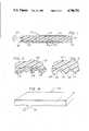
- FIG. 1is a lengthwise cross-sectional view of a fiber optic illuminator in accordance an embodiment of the invention
- FIG. 2is an enlarged portion of FIG. 1 at line 2;
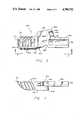
- FIG. 3is an enlarged cross-sectional view of a series of recesses formed in a fiber optic illuminator in accordance with another embodiment of the invention.
- FIG. 4is a perspective view of an illuminator in accordance with another embodiment of the invention, formed from a generally rectangular optically transmissive body;
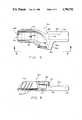
- FIG. 5is a bottom view of an optically transmissive dental tray in accordance with an embodiment of the invention.
- FIG. 6is a top view of the dental tray of FIG. 5;
- FIGS. 7 and 8are side views of the dental tray of FIG. 5.
- the present inventionis directed at optically transmissive bodies, which bodies have the characteristic of total internal reflection and are formed with one or more recesses. Each of these recesses is defined by two opposing surfaces which angle inwardly toward each other. A portion of the light traveling through the optically transmissive body is deflected by these surfaces in a direction to be emitted through the opposing side of the body.
- an optically transmissive bodyis illustrated.
- This bodyis in the form of an illuminator as seen generally at 10.
- the illuminator 10 illustrated in FIG. 1is formed from a optically transmissive fiber, that is, a fiber characterized by total internal reflection
- the optically transmissive body from which the illuminator of the invention may be formedincludes any desired shape, e.g., filamentous or rectangular.
- the material from which the body is preparedis the type of material which will provide that light can be directed through the length of the body by substantially total internal reflection.
- optically transmissive bodies useful for the purposes of the inventionare well known in the art. These materials will be those which allow for the transmission of light but have a refractive index greater than the refractive index of air. More expensive materials include various types of glass, while other materials include various types of acrylics and polystyrenes.
- non-filamentous bodieswill be constructed from a single material characterized by a refractive index which allows for the internal reflection to occur at the boundary of that material and the surrounding air.
- Fibrous optically transmissive bodiesmay be prepared in this manner but may also be formed to have a core prepared from a material having a first refractive index, which core is enveloped by another material having a second refractive index. By providing that the material forming the core is of a greater refractive index, the desired internal reflection of light is obtained.
- the fibrous illuminator 10is formed with an internal core 12 of material which is substantially transparent and has a first refractive index.
- This transparent core 12is substantially sheathed by an outer cladding 14 of a substantially transparent material having a second refractive index.
- the internal reflectionis provided by insuring that the refractive index of the cladding 14 material is less than the refractive index of the core 12 material.
- the optical fiber illuminator 10has first and second ends 16 and 18, with end 16 being illuminated by a light source 20.
- the light source 20which may be an incandescent bulb, may be used to illuminate the end 16 of more than one illuminator 10. This would increase the efficiency of the use of the particular light source 20.
- the lightwill pass through the end 16 and travel through the core 12 in accordance with known principles of internal reflection, i.e., Snell's law.
- Snell's lawa substantial portion of the light traveling through the core 12 will be angularly deflected across the core 12 at the interface between the core 12 and the outer cladding 14. It is further believed that if the light is directed at this interface at other than within a prescribed range of angles, the light will pass through the outer cladding 14. It is this general principle of which the invention makes use; however, since this is only a theory, the present invention should not be bound or limited in any manner by it.
- the illuminator 10 of the inventionis formed with one or more recesses 24, with the recesses 24 of the illustrated embodiment being arranged as a series of recesses 24 contained in a defined region, with one such region generally indicated at 22.
- the recesses 24 which form the region 22are defined by two opposing surfaces 26 and 28 which angle inwardly toward the fiber optic to define an included angle therebetween which, as will be discussed further herein, is such to cause the deflection of light toward the opposing side of the illuminator 10. This deflection occurs at the interface between the core 12 and the cladding 14; however, it is to be understood that an illuminator prepared from a fiber optic comprised of a single material will allow for this deflection at the interface between the material and the surrounding air.
- each of the recess 24 of the regions 22function to cause an emission of light out from the opposing side of the illuminator 10.
- a larger amount of lightis directed out of the illuminator.
- a single recessmay be formed in the fiber optic, or numerous recesses 24 may be formed at spaced apart locations.
- the individual recesses 24 of the defined region 22are preferably formed in a manner to insure that when the fiber optic being used to construct the illuminator 10 includes an outer cladding 14 that this outer cladding 14 remains intact. That is, the manner by which the individual recesses 24 are formed should insure the integrity of the cladding 14.
- Methods useful for manufacturing the optical illuminator 10 of the invention in this mannerinclude, but are not limited to, the various cast molding processes or injection molding process, whereby an optical fiber is continuously molded with one or more of the defined regions 22 of recesses 24 being formed during the molding process, or by a hot or cold embossing method where the individual recesses 24 are formed by deforming the surface of a virgin fiber optical rod at desired locations.
- the material of the fiber opticwill flow somewhat after the recess 24 is formed.
- the recesses 24, which are generally rectangular,are shaped to have their various corners rounded off, as seen better in FIG. 2.
- other methodsmay be used to form the individual recesses 24, e.g., machine cutting the optic fiber, with the resulting recess 24 having a more pronounced rectangular shape, as better seen in FIG. 3.
- the individual recesses 24may be spatially separated in the surface of the illuminator 10, even when arranged within a defined region 22 in accordance with a preferred embodiment, the individual recesses 24 are arranged contiguous to each other, as best seen in FIGS. 1 and 2. This manner of contiguously positioning the individual recesses 24 maximizes the illumination which will pass out of the opposing side of the illuminator 10.
- These recesses 24are defined by two opposing surfaces 26 and 28 which angle inwardly to define an "included" angle A therebetween, which angle A is generally from about seventy degrees to about one hundred ten degrees, more preferably from about eighty-five to about ninety-five degrees.
- angle Ais generally from about seventy degrees to about one hundred ten degrees, more preferably from about eighty-five to about ninety-five degrees.
- the depth of the individual recesses 24is not critical to the invention, that is, the individual recesses 24 do not have to be deep in comparison to the diameter of the optical fiber, or for that matter, any optically transmissive body, in order to function in accordance with the invention.
- the depth, indicated by the Arrow B, of the individual recesses 24may vary from about two to about eighty percent of the cross-sectional distance of the fiber optic, as indicated by the Arrow C in FIG. 1, or for that matter the cross-sectional distance of any shaped body forming an illuminator in accordance with the invention.
- this distanceis not critical, since it has been found that the amount of light deflected will not significantly differ with varying recess depths.
- the depth of the recess 24will affect the amount of light which will continue to pass through the illuminator 10, with the amount of light diminishing as the depth of the recess 24 increases.
- recesses of varying "included angles" and varying "depths”were formed in optical fibers having diameters of three sixteenths (3/16) of an inch. These fibers were of the type having an acrylic inner core and a styrene outer cladding. Light from a three candle power incandescent bulb was directed through the prepared fiber optic illuminators. The amount of light which was emitted out through the various recesses was measured, with good illumination, between one hundred and two hundred foot lamberts being demonstrated for recesses of varying depths, that is, recesses having depths of from 0.005" to 0.15", which is substantially equivalent to a depth of from about two to about eighty percent of the cross-sectional distance of the fiber.
- This recess 27which is formed in an illuminator 25, is also defined by two opposing surfaces 29 and 31 which angle inwardly toward each other.
- the recess 27 of this embodimentis formed by machine cutting, and as a result possesses sharper edges and corners than the recess 24 previously described.
- This type of recess 27, when formed in a virgin fiber optic having an outer cladding,will not retain the cladding as illustrated for the recess 24.
- both recesses 24 and 27provide ample illumination for the purposes of the invention, by forming the recess with a more rounded internal apex, that is, the top of the recess inside the illuminator as seen in FIG. 2, the illumination obtained is greater.
- the reason for this effectis believed to result from more light being deflected from the rounded sloped surface of the recess 24, as compared to the generally straight surface of the recess 27; however, this is merely a theory and is not to be construed to limit the scope of the invention.
- the recessesIn order to increase the illuminating characteristic of the recesses described herein, it is preferable to texturize one or both of the recesses' surfaces, with surfaces 29' and 31' of the recess 27' being illustrated as texturized in FIG. 3. This texturization increases the quantity of light which passes through the respective surface.
- the surfacescan be texturized by any suitable process, e.g., machining or sanding.
- FIG. 4illustrates an illuminator seen generally at 50 prepared from a rectangular shaped body of a material which, while transparent to light has a refractive index such that light will travel by substantially internal reflection therethrough.
- suitable materialsinclude but are not limited to acrylics and styrenes, polymers and certain types of glass.
- This illuminator 50is formed with a first region 52 of individual recesses 54.
- the recesses 54are individually formed in a manner similar to the manner by which the recesses 27 are formed, that is, the recesses 54 are formed by machine cutting. Thus the recesses 54 will resemble in appearance the recesses 27.
- an illumination sourceshould be positioned along various portions of the body.
- the illumination sourceis positioned at opposing ends of the body, such as at the ends 16 and 18 of the illuminator 10 illustrated in FIG. 1.
- a second light sourcesuch as an incandescent bulb may be positioned proximate both ends 16 and 18, it is preferable if a coating 30 of an illuminant material is applied to the end 18. This material will absorb and become illuminated by any light passing through the end 18.
- This coatingis preferably white and may either be a white paint or a white polymeric material applied to the end 18. As the light passes through the end 18 this white coating is illuminated and functions as a secondary light source to redirect any light which would normally pass out of the end 18 back through the illuminator 10.
- An illuminator prepared in this mannerwill possess increased efficiency.
- an optically transmissive dental tray prepared in accordance with an embodiment of the inventionis constructed from a material which allows for the transmission of light, but has a refractive index greater than the refractive index of air.
- examples of such materialsinclude various types of glass, acrylics and polystyrenes.
- the dental tray of the inventionis generally a trough-shaped body 62 formed from a material as discussed above which has the characteristic of total internal reflection.
- the trough-shaped body 62defines a channel 68 which traverses the length of the dental tray 60.
- the dental tray 60is formed with one or more recesses, as seen generally at 64.
- Each of these recesses 64are similar in form to the recesses 24 described above for the embodiment illustrated in FIGS. 1 and 2.
- each recess 24, and for this embodiment recesses 64are defined by two opposing surfaces which angle inwardly toward each other, preferably to define an included angle. A portion of the light traveling through the optically transmissive body 62 is deflected by these surfaces. A portion of the deflected light is emitted through the opposing surface of the body 62, which is in effect the surfaces of the dental tray forming the channel 68.
- the various angular relationships between the surfaces of the recesses 64are the same as described above for the recesses 24.
- These recesses 64may also be formed in accordance with the various methods discussed above for forming the recesses 24 illustrated in FIGS. 1 and 2, as well as those methods discussed above for forming the recess 27 illustrated in FIG. 3. Futhermore, those modifications described above for the recesses illustrated in FIGS. 1-4 may also be incorporated in the recesses 64 of this embodiment.
- the roughened surfaces described above for the embodiment illustrated in FIG. 3may be incorporated in a similar recess for the dental tray 60.
- the multiple recesses 64are formed in the outermost surface of the dental tray 60, with this outermost surface indicated generally at 66. These recesses 64 will thus deflect any light passing through the body 62 in a general inward direction. This will direct the light into the channel 68.
- the body 62includes a base wall 70 out from which extends two substantially parallel and opposing side walls 72 and 74. These various walls 70, 72 and 74 define the channel 68.
- the side walls 72 and 74are contoured to curve the channel 68 sufficiently to receive at least a partial arch-shaped group of a patient's teeth.
- the two side walls 72 and 74are sufficiently separated to provide a cross-section wider than the teeth to be received in the channel 68.
- the various recesses 64are formed in the outermost surface 66 of each of the side walls 72 and 74, as well as, the base wall 70. While the embodiment illustrated in FIGS. 5-8, illustrates non-continuing multiple recesses 64 which are separately formed as three separate sections in each outermost surface 66 of each wall 70, 72 and 74, multiple, single recesses 64 can be continuously formed in the outermost surface 66 of the respective walls 70, 72 and 74.
- the various recesses 64are formed substantially parallel and contiguous to each other substantially along the length of the dental tray body 62. However, one or more of the recesses 64, such as the recess indicated at 65, may be positioned at an angle to the other recesses 64 in order to ensure that the light is substantially deflected inward to all areas of the channel 68. That is, by properly positioning the recesses 64, the light traveling through the body 62 is incrementally deflected inward to illuminate substantially the entire length of the channel 68.
- Adjacent recesses 64may be spatially separated from each other at varying distances. The precise spatial separation between adjacent recesses 64 is dependent upon the desired amount of illumination for the channel 86. This desired amount of illumination is dependent upon the light source being used, and the amount of illumination necessary to satisfactorily initiate the polymerization or curing of any material deposited in the channel 68. As will be discussed more fully herein a material is deposited in the channel 68 for the purpose of preparing a dental impression of a patient's teeth.
- the dental tray 60is further formed with at least a first primary light portal, seen generally at 76.
- This portal 76is generally a flat surface against which a light source is positioned. As seen in the FIGS. 5-8 this portal 76 forms the end of a tubular conduit 78 formed in a handle 80, which handle 80 is integrally formed with and protrudes outward from the dental tray body 62.
- the handle 80is grasped by a technican during the positioning of the dental tray 60 in the mouth of a patient, and is also grasped while removing the dental tray 60.
- any suitable light sourcenot shown, which is receivable in the tubular conduit 78 for directing light towards the portal 76 can be used with the dental tray 60.
- An example of a suitable light sourceis disclosed in U.S. Pat. No. 4,386,344, issued to Gonser, on May 24, 1983.
- the preferred amount of illumination to be provided by the selected light sourceis within the range of 360 to 600 nanometers.
- the amount of illumination provided by the selected light sourceshould be compatible with the amount of illumination necessary for initiating the polymerization of any material deposited in the channel 68. Further, the amount of illumination provided by the light source should also be compatible with the number of recesses 64 formed in the body 62 to provide the necessary amount of illumination in the channel 68.
- the body 62is further formed at the juncture between the body 62 and the handle 80 with a notch 82.
- this notch 82is a generally tear-shaped depression having a cross-section larger than the recesses 64, and is positioned contiguous to the end of the handle 80.
- the positioning and shape of the notch 82is specifically choosen to deflect the light passing through the portal 76 down through the length of the dental tray body 62. This ensures that a maximum amount of the light will travel through the tray body 62 to impinge upon the recesses 64.
- this notch 82is dependent upon the amount of illumination being directed through the portal 76, and the amount of illumination necessary in the channel 68 to initiate the desired polymerization. For that matter, if the light source being used provides sufficient illumination there is no necessity to form the body 62 with a notch 82. That is, the selected light source may direct such a large amount of light through the portal 76, and thus through the dental tray body 62, that the channel 68 will receive an excess amount of illumination. In this case a notch 82 is not required, since this notch 82 is typically provided to ensure that a sufficient amount of light will travel through the body 62 to provide the desired degree of illumination in the channel 68.
- the dental tray body 62is integrally formed with a secondary light portal 84.
- This light portal 84is positioned at the end of a secondary conduit 86 formed in a shoulder 88, which shoulder 88 extends out from the handle 80.
- the conduit 86is also dimensioned to receive a suitable light source, not shown.
- the dental tray body 62, handle 80 and shoulder 88are integrally formed from the optically transmissive material. Furthermore the various recesses 64, and notch 82, are integrally formed in the dental tray body 62 during the initial formed process in a manner as described above for the embodiment illustrated in FIGS. 1 and 2, otherwise, the various recesses 64 and 82 may be formed in a previously formed dental tray 60 by a cutting operation as described for the embodiment illustrated in FIG. 3.
- the dental tray of the inventionis used to prepare a dental impression of a patient's teeth using a light curable or polymerizable material.
- Any suitable polymeric materialmay be used for the purposes of the invention, with the selected material required to be flowable and be either light curable or polymerizable. That is, the polymeric material useful for the practice of the invention is either of the type which will cure upon receiving satisfactory illumination, or be of the type which is polymerized upon receiving satisfactory illumination.
- a suitable light polymerizable or curable materialis deposited in the channel 68.
- the dental tray 60is positioned in a patient's mouth. A selected portion of the patient's teeth is embedded into the material.
- a suitable light sourceis positioned in the conduit 78 to direct light through the portal 76. The light will enter and pass through the dental tray body 62, and will be deflected towards the material in the channel 68 by the respectively positioned recesses 64. After the necessary amount of time has lapsed the dental tray 60, with the now cured or polymerized material is removed from the patient's mouth.
- the light sourceis positioned in the conduit 86 to direct light through the portal 84.
- the method of preparing a dental impressionmay be substantially completed within about three minutes, typically within about one minute.
Landscapes
- Physics & Mathematics (AREA)
- Health & Medical Sciences (AREA)
- Optics & Photonics (AREA)
- General Physics & Mathematics (AREA)
- Epidemiology (AREA)
- Animal Behavior & Ethology (AREA)
- General Health & Medical Sciences (AREA)
- Public Health (AREA)
- Veterinary Medicine (AREA)
- Life Sciences & Earth Sciences (AREA)
- Dentistry (AREA)
- Oral & Maxillofacial Surgery (AREA)
- Dental Tools And Instruments Or Auxiliary Dental Instruments (AREA)
Abstract
Description
Claims (23)
Priority Applications (1)
| Application Number | Priority Date | Filing Date | Title |
|---|---|---|---|
| US07/115,668US4790752A (en) | 1987-01-30 | 1987-11-02 | Illuminated dental impression tray |
Applications Claiming Priority (2)
| Application Number | Priority Date | Filing Date | Title |
|---|---|---|---|
| US07/009,413US4765701A (en) | 1987-01-30 | 1987-01-30 | Illuminator optical fiber rod |
| US07/115,668US4790752A (en) | 1987-01-30 | 1987-11-02 | Illuminated dental impression tray |
Related Parent Applications (1)
| Application Number | Title | Priority Date | Filing Date |
|---|---|---|---|
| US07/009,413Continuation-In-PartUS4765701A (en) | 1987-01-30 | 1987-01-30 | Illuminator optical fiber rod |
Publications (1)
| Publication Number | Publication Date |
|---|---|
| US4790752Atrue US4790752A (en) | 1988-12-13 |
Family
ID=26679436
Family Applications (1)
| Application Number | Title | Priority Date | Filing Date |
|---|---|---|---|
| US07/115,668Expired - LifetimeUS4790752A (en) | 1987-01-30 | 1987-11-02 | Illuminated dental impression tray |
Country Status (1)
| Country | Link |
|---|---|
| US (1) | US4790752A (en) |
Cited By (96)
| Publication number | Priority date | Publication date | Assignee | Title |
|---|---|---|---|---|
| US5316473A (en)* | 1988-06-17 | 1994-05-31 | Dentsply Research & Development Corp. | Light curing apparatus and method |
| US5487662A (en)* | 1994-03-22 | 1996-01-30 | Minnesota Mining And Manufacturing Company | Dental impression tray for photocurable impression material |
| USD383845S (en)* | 1996-04-08 | 1997-09-16 | Confi-Dental Products Company | Dental impression tray |
| US5702250A (en)* | 1996-07-19 | 1997-12-30 | Minnesota Mining And Manufacturing Co. | Compact dental impression tray for photocurable impression material |
| US5711595A (en)* | 1995-08-23 | 1998-01-27 | Gerbe; James Robert | Illuminated serving tray |
| US5718577A (en)* | 1996-03-15 | 1998-02-17 | Minnesota Mining & Manufacturing | Dental impression tray with chemiluminescent light source |
| USD392675S (en) | 1997-04-21 | 1998-03-24 | Irma Maritza Perez | Arithmetic instuctional apparatus |
| US5890896A (en)* | 1996-03-15 | 1999-04-06 | Padial; Jose Jesus Castro | Device for the application of an impression material to the occlusal surface of teeth |
| WO1999040870A1 (en)* | 1998-02-13 | 1999-08-19 | Britesmile, Inc. | Light-activated tooth whitening composition and method of using same |
| WO2000032984A1 (en)* | 1998-12-02 | 2000-06-08 | 3M Innovative Properties Company | Apparatus for molding light extraction structures onto a light guide |
| US6185356B1 (en) | 1995-06-27 | 2001-02-06 | Lumitex, Inc. | Protective cover for a lighting device |
| US20020001202A1 (en)* | 1997-07-02 | 2002-01-03 | Williams Jeffrey B. | Light delivery systems and applications thereof |
| US6416319B1 (en) | 1998-02-13 | 2002-07-09 | Britesmile, Inc. | Tooth whitening device and method of using same |
| US20030095781A1 (en)* | 1997-07-02 | 2003-05-22 | Williams Jeffrey B. | Illuminated surgical retractor |
| US6591049B2 (en) | 1997-07-02 | 2003-07-08 | Lumitex, Inc. | Light delivery systems and applications thereof |
| US20030156431A1 (en)* | 2001-12-31 | 2003-08-21 | Gozum John E. | Illumination device |
| WO2003058302A3 (en)* | 2001-12-31 | 2003-08-28 | 3M Innovative Properties Co | Light fiber comprising continuous outer cladding and method of making |
| US20040053189A1 (en)* | 2002-09-13 | 2004-03-18 | Joshua Friedman | Dental light curing member and method |
| US20050048434A1 (en)* | 1998-02-13 | 2005-03-03 | Cipolla Anthony J. | Apparatus for simultaneous illumination of teeth |
| US20050171408A1 (en)* | 1997-07-02 | 2005-08-04 | Parker Jeffery R. | Light delivery systems and applications thereof |
| US20050265933A1 (en)* | 1998-02-13 | 2005-12-01 | Montgomery Robert E | Light-activated tooth whitening method |
| USD543280S1 (en) | 2005-04-01 | 2007-05-22 | Ajit Khubani | Light activated tooth whitening apparatus |
| US20100216089A1 (en)* | 2005-06-01 | 2010-08-26 | Cao Group, Inc. | Three Dimensional Curing Light |
| US20110189626A1 (en)* | 2010-01-29 | 2011-08-04 | Engineered Cosmetic Solutions, LLC | Teeth whitening system, apparatus, and related method |
| US8047987B2 (en) | 2006-05-26 | 2011-11-01 | Invuity, Inc. | Blade insert illuminator |
| US8088066B2 (en) | 2007-10-24 | 2012-01-03 | Invuity, Inc. | Blade insert illuminator |
| US8409088B2 (en) | 2006-01-18 | 2013-04-02 | Invuity, Inc. | Retractor illumination system |
| US20140080082A1 (en)* | 2012-09-14 | 2014-03-20 | Orthoaccel Technologies Inc. | Light cure bite plate for orthodontic remodeling devices |
| US8921440B2 (en) | 2010-04-22 | 2014-12-30 | 3M Innovative Properties Company | Radiation curable composition, process of production and use thereof |
| GB2526800A (en)* | 2014-06-02 | 2015-12-09 | Mavrik Dental Systems Ltd | An anatomical drape device |
| US20170135792A1 (en)* | 2015-11-12 | 2017-05-18 | Align Technology, Inc. | Dental attachment formation structure |
| US10166402B2 (en) | 2013-05-16 | 2019-01-01 | Excelitas Technologies Corp. | Visible light photo-disinfection patch |
| US20190046297A1 (en)* | 2017-08-11 | 2019-02-14 | Align Technology, Inc. | Devices and systems for creation of attachments for use with dental appliances and changeable shaped attachments |
| US10390913B2 (en) | 2018-01-26 | 2019-08-27 | Align Technology, Inc. | Diagnostic intraoral scanning |
| US10413385B2 (en) | 2004-02-27 | 2019-09-17 | Align Technology, Inc. | Method and system for providing dynamic orthodontic assessment and treatment profiles |
| US10421152B2 (en) | 2011-09-21 | 2019-09-24 | Align Technology, Inc. | Laser cutting |
| US10470847B2 (en) | 2016-06-17 | 2019-11-12 | Align Technology, Inc. | Intraoral appliances with sensing |
| US10504386B2 (en) | 2015-01-27 | 2019-12-10 | Align Technology, Inc. | Training method and system for oral-cavity-imaging-and-modeling equipment |
| US10509838B2 (en) | 2016-07-27 | 2019-12-17 | Align Technology, Inc. | Methods and apparatuses for forming a three-dimensional volumetric model of a subject's teeth |
| US10517482B2 (en) | 2017-07-27 | 2019-12-31 | Align Technology, Inc. | Optical coherence tomography for orthodontic aligners |
| US10524881B2 (en) | 2010-04-30 | 2020-01-07 | Align Technology, Inc. | Patterned dental positioning appliance |
| US20200008915A1 (en)* | 2017-03-28 | 2020-01-09 | Koninklijke Philips N.V. | Teeth illumination device with a light core |
| US10537405B2 (en) | 2014-11-13 | 2020-01-21 | Align Technology, Inc. | Dental appliance with cavity for an unerupted or erupting tooth |
| US10543064B2 (en) | 2008-05-23 | 2020-01-28 | Align Technology, Inc. | Dental implant positioning |
| US10548700B2 (en) | 2016-12-16 | 2020-02-04 | Align Technology, Inc. | Dental appliance etch template |
| US10595966B2 (en) | 2016-11-04 | 2020-03-24 | Align Technology, Inc. | Methods and apparatuses for dental images |
| US10613515B2 (en) | 2017-03-31 | 2020-04-07 | Align Technology, Inc. | Orthodontic appliances including at least partially un-erupted teeth and method of forming them |
| US10610332B2 (en) | 2012-05-22 | 2020-04-07 | Align Technology, Inc. | Adjustment of tooth position in a virtual dental model |
| US10639134B2 (en) | 2017-06-26 | 2020-05-05 | Align Technology, Inc. | Biosensor performance indicator for intraoral appliances |
| US10758321B2 (en) | 2008-05-23 | 2020-09-01 | Align Technology, Inc. | Smile designer |
| US10779718B2 (en) | 2017-02-13 | 2020-09-22 | Align Technology, Inc. | Cheek retractor and mobile device holder |
| US10813720B2 (en) | 2017-10-05 | 2020-10-27 | Align Technology, Inc. | Interproximal reduction templates |
| US10842601B2 (en) | 2008-06-12 | 2020-11-24 | Align Technology, Inc. | Dental appliance |
| US10885521B2 (en) | 2017-07-17 | 2021-01-05 | Align Technology, Inc. | Method and apparatuses for interactive ordering of dental aligners |
| US10893918B2 (en) | 2012-03-01 | 2021-01-19 | Align Technology, Inc. | Determining a dental treatment difficulty |
| US10919209B2 (en) | 2009-08-13 | 2021-02-16 | Align Technology, Inc. | Method of forming a dental appliance |
| US10980613B2 (en) | 2017-12-29 | 2021-04-20 | Align Technology, Inc. | Augmented reality enhancements for dental practitioners |
| US10993783B2 (en) | 2016-12-02 | 2021-05-04 | Align Technology, Inc. | Methods and apparatuses for customizing a rapid palatal expander |
| US11026768B2 (en) | 1998-10-08 | 2021-06-08 | Align Technology, Inc. | Dental appliance reinforcement |
| US11026831B2 (en) | 2016-12-02 | 2021-06-08 | Align Technology, Inc. | Dental appliance features for speech enhancement |
| US11045283B2 (en) | 2017-06-09 | 2021-06-29 | Align Technology, Inc. | Palatal expander with skeletal anchorage devices |
| US11083545B2 (en) | 2009-03-19 | 2021-08-10 | Align Technology, Inc. | Dental wire attachment |
| US11096763B2 (en) | 2017-11-01 | 2021-08-24 | Align Technology, Inc. | Automatic treatment planning |
| US11103330B2 (en) | 2015-12-09 | 2021-08-31 | Align Technology, Inc. | Dental attachment placement structure |
| US11116605B2 (en) | 2017-08-15 | 2021-09-14 | Align Technology, Inc. | Buccal corridor assessment and computation |
| US11123156B2 (en) | 2017-08-17 | 2021-09-21 | Align Technology, Inc. | Dental appliance compliance monitoring |
| US11213368B2 (en) | 2008-03-25 | 2022-01-04 | Align Technology, Inc. | Reconstruction of non-visible part of tooth |
| US11219506B2 (en) | 2017-11-30 | 2022-01-11 | Align Technology, Inc. | Sensors for monitoring oral appliances |
| US11273011B2 (en) | 2016-12-02 | 2022-03-15 | Align Technology, Inc. | Palatal expanders and methods of expanding a palate |
| GR1010240B (en)* | 2021-07-30 | 2022-05-27 | Ευαγγελος Στυλιανου Μητσης | Oral angles recording device |
| US11376101B2 (en) | 2016-12-02 | 2022-07-05 | Align Technology, Inc. | Force control, stop mechanism, regulating structure of removable arch adjustment appliance |
| US11382711B2 (en) | 2008-08-13 | 2022-07-12 | Invuity, Inc. | Cyclo olefin polymer and copolymer medical devices |
| US11419702B2 (en) | 2017-07-21 | 2022-08-23 | Align Technology, Inc. | Palatal contour anchorage |
| US11426259B2 (en) | 2012-02-02 | 2022-08-30 | Align Technology, Inc. | Identifying forces on a tooth |
| US11432908B2 (en) | 2017-12-15 | 2022-09-06 | Align Technology, Inc. | Closed loop adaptive orthodontic treatment methods and apparatuses |
| US11436191B2 (en) | 2007-11-08 | 2022-09-06 | Align Technology, Inc. | Systems and methods for anonymizing patent images in relation to a clinical data file |
| US11458003B2 (en)* | 2017-01-11 | 2022-10-04 | Koninklijke Philips N.V. | Teeth illumination device with a light guide |
| US11471252B2 (en) | 2008-10-08 | 2022-10-18 | Align Technology, Inc. | Dental positioning appliance having mesh portion |
| US11534268B2 (en) | 2017-10-27 | 2022-12-27 | Align Technology, Inc. | Alternative bite adjustment structures |
| US11534974B2 (en) | 2017-11-17 | 2022-12-27 | Align Technology, Inc. | Customized fabrication of orthodontic retainers based on patient anatomy |
| US11564777B2 (en) | 2018-04-11 | 2023-01-31 | Align Technology, Inc. | Releasable palatal expanders |
| US11576752B2 (en) | 2017-10-31 | 2023-02-14 | Align Technology, Inc. | Dental appliance having selective occlusal loading and controlled intercuspation |
| US11596502B2 (en) | 2015-12-09 | 2023-03-07 | Align Technology, Inc. | Dental attachment placement structure |
| US11612454B2 (en) | 2010-04-30 | 2023-03-28 | Align Technology, Inc. | Individualized orthodontic treatment index |
| US11612455B2 (en) | 2016-06-17 | 2023-03-28 | Align Technology, Inc. | Orthodontic appliance performance monitor |
| US11633268B2 (en) | 2017-07-27 | 2023-04-25 | Align Technology, Inc. | Tooth shading, transparency and glazing |
| US11638629B2 (en) | 2014-09-19 | 2023-05-02 | Align Technology, Inc. | Arch expanding appliance |
| US11717384B2 (en) | 2007-05-25 | 2023-08-08 | Align Technology, Inc. | Dental appliance with eruption tabs |
| US11744677B2 (en) | 2014-09-19 | 2023-09-05 | Align Technology, Inc. | Arch adjustment appliance |
| US11931222B2 (en) | 2015-11-12 | 2024-03-19 | Align Technology, Inc. | Dental attachment formation structures |
| US11937991B2 (en) | 2018-03-27 | 2024-03-26 | Align Technology, Inc. | Dental attachment placement structure |
| US11996181B2 (en) | 2017-06-16 | 2024-05-28 | Align Technology, Inc. | Automatic detection of tooth type and eruption status |
| US12090020B2 (en) | 2017-03-27 | 2024-09-17 | Align Technology, Inc. | Apparatuses and methods assisting in dental therapies |
| US20240382294A1 (en)* | 2021-10-01 | 2024-11-21 | Rafat Al Mstrehi | Impression tray |
| US12171575B2 (en) | 2017-10-04 | 2024-12-24 | Align Technology, Inc. | Intraoral systems and methods for sampling soft-tissue |
| US12245909B2 (en) | 2019-05-16 | 2025-03-11 | Koninklijke Philips N.V. | Mouthpiece component and method of manufacture |
Citations (2)
| Publication number | Priority date | Publication date | Assignee | Title |
|---|---|---|---|---|
| US4553936A (en)* | 1984-07-31 | 1985-11-19 | Dentsply Research & Development Corp. | Dental impression tray and method of use |
| US4631030A (en)* | 1984-07-09 | 1986-12-23 | Hawe-Neos Dental Dr. H. Von Weissenfluh S.A. | Equipment for putting in approximal fillings with light-hardening materials |
- 1987
- 1987-11-02USUS07/115,668patent/US4790752A/ennot_activeExpired - Lifetime
Patent Citations (2)
| Publication number | Priority date | Publication date | Assignee | Title |
|---|---|---|---|---|
| US4631030A (en)* | 1984-07-09 | 1986-12-23 | Hawe-Neos Dental Dr. H. Von Weissenfluh S.A. | Equipment for putting in approximal fillings with light-hardening materials |
| US4553936A (en)* | 1984-07-31 | 1985-11-19 | Dentsply Research & Development Corp. | Dental impression tray and method of use |
Cited By (128)
| Publication number | Priority date | Publication date | Assignee | Title |
|---|---|---|---|---|
| US5316473A (en)* | 1988-06-17 | 1994-05-31 | Dentsply Research & Development Corp. | Light curing apparatus and method |
| US5487662A (en)* | 1994-03-22 | 1996-01-30 | Minnesota Mining And Manufacturing Company | Dental impression tray for photocurable impression material |
| EP0678282A3 (en)* | 1994-03-22 | 1997-01-02 | Minnesota Mining & Mfg | Dental impression tray for photocurable impression material. |
| US6185356B1 (en) | 1995-06-27 | 2001-02-06 | Lumitex, Inc. | Protective cover for a lighting device |
| US6504985B2 (en) | 1995-06-27 | 2003-01-07 | Lumitex, Inc. | Illuminated surgical retractor |
| US5711595A (en)* | 1995-08-23 | 1998-01-27 | Gerbe; James Robert | Illuminated serving tray |
| US5718577A (en)* | 1996-03-15 | 1998-02-17 | Minnesota Mining & Manufacturing | Dental impression tray with chemiluminescent light source |
| US5890896A (en)* | 1996-03-15 | 1999-04-06 | Padial; Jose Jesus Castro | Device for the application of an impression material to the occlusal surface of teeth |
| USD383845S (en)* | 1996-04-08 | 1997-09-16 | Confi-Dental Products Company | Dental impression tray |
| US5702250A (en)* | 1996-07-19 | 1997-12-30 | Minnesota Mining And Manufacturing Co. | Compact dental impression tray for photocurable impression material |
| USD392675S (en) | 1997-04-21 | 1998-03-24 | Irma Maritza Perez | Arithmetic instuctional apparatus |
| US20060217596A1 (en)* | 1997-07-02 | 2006-09-28 | Lumitex, Inc. | Illuminated surgical retractor |
| US20020001202A1 (en)* | 1997-07-02 | 2002-01-03 | Williams Jeffrey B. | Light delivery systems and applications thereof |
| US20050171408A1 (en)* | 1997-07-02 | 2005-08-04 | Parker Jeffery R. | Light delivery systems and applications thereof |
| US6739744B2 (en) | 1997-07-02 | 2004-05-25 | Lumitex, Inc. | Light delivery systems and applications thereof |
| US20030095781A1 (en)* | 1997-07-02 | 2003-05-22 | Williams Jeffrey B. | Illuminated surgical retractor |
| US6591049B2 (en) | 1997-07-02 | 2003-07-08 | Lumitex, Inc. | Light delivery systems and applications thereof |
| US7306559B2 (en) | 1997-07-02 | 2007-12-11 | Lumitex, Inc. | Illuminated surgical retractor |
| US20050265933A1 (en)* | 1998-02-13 | 2005-12-01 | Montgomery Robert E | Light-activated tooth whitening method |
| WO1999040870A1 (en)* | 1998-02-13 | 1999-08-19 | Britesmile, Inc. | Light-activated tooth whitening composition and method of using same |
| US8562955B2 (en) | 1998-02-13 | 2013-10-22 | Discus Dental, Llc | Light-activated tooth whitening method |
| US7572124B2 (en) | 1998-02-13 | 2009-08-11 | Discus Dental, Llc | Apparatus for simultaneous illumination of teeth |
| US20050048434A1 (en)* | 1998-02-13 | 2005-03-03 | Cipolla Anthony J. | Apparatus for simultaneous illumination of teeth |
| US6416319B1 (en) | 1998-02-13 | 2002-07-09 | Britesmile, Inc. | Tooth whitening device and method of using same |
| US11026768B2 (en) | 1998-10-08 | 2021-06-08 | Align Technology, Inc. | Dental appliance reinforcement |
| WO2000032984A1 (en)* | 1998-12-02 | 2000-06-08 | 3M Innovative Properties Company | Apparatus for molding light extraction structures onto a light guide |
| US20030156431A1 (en)* | 2001-12-31 | 2003-08-21 | Gozum John E. | Illumination device |
| US6799880B2 (en) | 2001-12-31 | 2004-10-05 | 3M Innovative Properties Company | Illumination device |
| WO2003058302A3 (en)* | 2001-12-31 | 2003-08-28 | 3M Innovative Properties Co | Light fiber comprising continuous outer cladding and method of making |
| US20040053189A1 (en)* | 2002-09-13 | 2004-03-18 | Joshua Friedman | Dental light curing member and method |
| US7094057B2 (en)* | 2002-09-13 | 2006-08-22 | Joshua Friedman | Dental light curing member and method |
| US10413385B2 (en) | 2004-02-27 | 2019-09-17 | Align Technology, Inc. | Method and system for providing dynamic orthodontic assessment and treatment profiles |
| USD543280S1 (en) | 2005-04-01 | 2007-05-22 | Ajit Khubani | Light activated tooth whitening apparatus |
| US9295537B2 (en)* | 2005-06-01 | 2016-03-29 | Cao Group, Inc. | Three dimensional curing light |
| US20100216089A1 (en)* | 2005-06-01 | 2010-08-26 | Cao Group, Inc. | Three Dimensional Curing Light |
| US8409088B2 (en) | 2006-01-18 | 2013-04-02 | Invuity, Inc. | Retractor illumination system |
| US9055935B2 (en) | 2006-01-18 | 2015-06-16 | Invuity, Inc. | Retractor illumination system |
| US9844364B2 (en) | 2006-01-18 | 2017-12-19 | Invuity, Inc. | Retractor illumination system |
| US9271710B2 (en) | 2006-01-18 | 2016-03-01 | Invuity, Inc. | Retractor illumination system |
| US9271709B2 (en) | 2006-01-18 | 2016-03-01 | Invuity, Inc. | Retractor illumination system |
| US8047987B2 (en) | 2006-05-26 | 2011-11-01 | Invuity, Inc. | Blade insert illuminator |
| US9877639B2 (en) | 2006-05-26 | 2018-01-30 | Invuity, Inc. | Blade insert illuminator |
| US8920316B2 (en) | 2006-05-26 | 2014-12-30 | Invuity, Inc. | Blade insert illuminator |
| US9241617B2 (en) | 2006-05-26 | 2016-01-26 | Invuity, Inc. | Blade insert illuminator |
| US11717384B2 (en) | 2007-05-25 | 2023-08-08 | Align Technology, Inc. | Dental appliance with eruption tabs |
| US11583175B2 (en) | 2007-10-24 | 2023-02-21 | Invuity, Inc. | Blade insert illuminator |
| US10582844B2 (en) | 2007-10-24 | 2020-03-10 | Invuity, Inc. | Blade insert illuminator |
| US12161301B2 (en) | 2007-10-24 | 2024-12-10 | Invuity, Inc. | Blade insert illuminator |
| US9060707B2 (en) | 2007-10-24 | 2015-06-23 | Invuity, Inc. | Blade insert illuminator |
| US8088066B2 (en) | 2007-10-24 | 2012-01-03 | Invuity, Inc. | Blade insert illuminator |
| US9986901B2 (en) | 2007-10-24 | 2018-06-05 | Invuity, Inc. | Blade insert illuminator |
| US9468366B2 (en) | 2007-10-24 | 2016-10-18 | Invuity, Inc. | Blade insert illuminator |
| US11436191B2 (en) | 2007-11-08 | 2022-09-06 | Align Technology, Inc. | Systems and methods for anonymizing patent images in relation to a clinical data file |
| US11213368B2 (en) | 2008-03-25 | 2022-01-04 | Align Technology, Inc. | Reconstruction of non-visible part of tooth |
| US10758321B2 (en) | 2008-05-23 | 2020-09-01 | Align Technology, Inc. | Smile designer |
| US10543064B2 (en) | 2008-05-23 | 2020-01-28 | Align Technology, Inc. | Dental implant positioning |
| US10842601B2 (en) | 2008-06-12 | 2020-11-24 | Align Technology, Inc. | Dental appliance |
| US11382711B2 (en) | 2008-08-13 | 2022-07-12 | Invuity, Inc. | Cyclo olefin polymer and copolymer medical devices |
| US11471252B2 (en) | 2008-10-08 | 2022-10-18 | Align Technology, Inc. | Dental positioning appliance having mesh portion |
| US11083545B2 (en) | 2009-03-19 | 2021-08-10 | Align Technology, Inc. | Dental wire attachment |
| US10919209B2 (en) | 2009-08-13 | 2021-02-16 | Align Technology, Inc. | Method of forming a dental appliance |
| US20110189626A1 (en)* | 2010-01-29 | 2011-08-04 | Engineered Cosmetic Solutions, LLC | Teeth whitening system, apparatus, and related method |
| US8921440B2 (en) | 2010-04-22 | 2014-12-30 | 3M Innovative Properties Company | Radiation curable composition, process of production and use thereof |
| US11612454B2 (en) | 2010-04-30 | 2023-03-28 | Align Technology, Inc. | Individualized orthodontic treatment index |
| US10524881B2 (en) | 2010-04-30 | 2020-01-07 | Align Technology, Inc. | Patterned dental positioning appliance |
| US10421152B2 (en) | 2011-09-21 | 2019-09-24 | Align Technology, Inc. | Laser cutting |
| US10828719B2 (en) | 2011-09-21 | 2020-11-10 | Align Technology, Inc. | Laser cutting |
| US11426259B2 (en) | 2012-02-02 | 2022-08-30 | Align Technology, Inc. | Identifying forces on a tooth |
| US10893918B2 (en) | 2012-03-01 | 2021-01-19 | Align Technology, Inc. | Determining a dental treatment difficulty |
| US10610332B2 (en) | 2012-05-22 | 2020-04-07 | Align Technology, Inc. | Adjustment of tooth position in a virtual dental model |
| US20140080082A1 (en)* | 2012-09-14 | 2014-03-20 | Orthoaccel Technologies Inc. | Light cure bite plate for orthodontic remodeling devices |
| US10166402B2 (en) | 2013-05-16 | 2019-01-01 | Excelitas Technologies Corp. | Visible light photo-disinfection patch |
| AU2015270113B2 (en)* | 2014-06-02 | 2020-01-30 | Mavrik Dental Systems Ltd. | An anatomical drape device |
| GB2526800A (en)* | 2014-06-02 | 2015-12-09 | Mavrik Dental Systems Ltd | An anatomical drape device |
| US11638629B2 (en) | 2014-09-19 | 2023-05-02 | Align Technology, Inc. | Arch expanding appliance |
| US11744677B2 (en) | 2014-09-19 | 2023-09-05 | Align Technology, Inc. | Arch adjustment appliance |
| US10537405B2 (en) | 2014-11-13 | 2020-01-21 | Align Technology, Inc. | Dental appliance with cavity for an unerupted or erupting tooth |
| US10504386B2 (en) | 2015-01-27 | 2019-12-10 | Align Technology, Inc. | Training method and system for oral-cavity-imaging-and-modeling equipment |
| US11554000B2 (en)* | 2015-11-12 | 2023-01-17 | Align Technology, Inc. | Dental attachment formation structure |
| US20170135792A1 (en)* | 2015-11-12 | 2017-05-18 | Align Technology, Inc. | Dental attachment formation structure |
| US11931222B2 (en) | 2015-11-12 | 2024-03-19 | Align Technology, Inc. | Dental attachment formation structures |
| US11103330B2 (en) | 2015-12-09 | 2021-08-31 | Align Technology, Inc. | Dental attachment placement structure |
| US11596502B2 (en) | 2015-12-09 | 2023-03-07 | Align Technology, Inc. | Dental attachment placement structure |
| US10470847B2 (en) | 2016-06-17 | 2019-11-12 | Align Technology, Inc. | Intraoral appliances with sensing |
| US11612455B2 (en) | 2016-06-17 | 2023-03-28 | Align Technology, Inc. | Orthodontic appliance performance monitor |
| US10509838B2 (en) | 2016-07-27 | 2019-12-17 | Align Technology, Inc. | Methods and apparatuses for forming a three-dimensional volumetric model of a subject's teeth |
| US10606911B2 (en) | 2016-07-27 | 2020-03-31 | Align Technology, Inc. | Intraoral scanner with dental diagnostics capabilities |
| US10585958B2 (en) | 2016-07-27 | 2020-03-10 | Align Technology, Inc. | Intraoral scanner with dental diagnostics capabilities |
| US10595966B2 (en) | 2016-11-04 | 2020-03-24 | Align Technology, Inc. | Methods and apparatuses for dental images |
| US11026831B2 (en) | 2016-12-02 | 2021-06-08 | Align Technology, Inc. | Dental appliance features for speech enhancement |
| US11376101B2 (en) | 2016-12-02 | 2022-07-05 | Align Technology, Inc. | Force control, stop mechanism, regulating structure of removable arch adjustment appliance |
| US10993783B2 (en) | 2016-12-02 | 2021-05-04 | Align Technology, Inc. | Methods and apparatuses for customizing a rapid palatal expander |
| US11273011B2 (en) | 2016-12-02 | 2022-03-15 | Align Technology, Inc. | Palatal expanders and methods of expanding a palate |
| US10548700B2 (en) | 2016-12-16 | 2020-02-04 | Align Technology, Inc. | Dental appliance etch template |
| US11458003B2 (en)* | 2017-01-11 | 2022-10-04 | Koninklijke Philips N.V. | Teeth illumination device with a light guide |
| US10779718B2 (en) | 2017-02-13 | 2020-09-22 | Align Technology, Inc. | Cheek retractor and mobile device holder |
| US12090020B2 (en) | 2017-03-27 | 2024-09-17 | Align Technology, Inc. | Apparatuses and methods assisting in dental therapies |
| US20200008915A1 (en)* | 2017-03-28 | 2020-01-09 | Koninklijke Philips N.V. | Teeth illumination device with a light core |
| US10758330B2 (en)* | 2017-03-28 | 2020-09-01 | Koninklijke Philips N.V. | Teeth illumination device with a light core |
| US10613515B2 (en) | 2017-03-31 | 2020-04-07 | Align Technology, Inc. | Orthodontic appliances including at least partially un-erupted teeth and method of forming them |
| US11045283B2 (en) | 2017-06-09 | 2021-06-29 | Align Technology, Inc. | Palatal expander with skeletal anchorage devices |
| US11996181B2 (en) | 2017-06-16 | 2024-05-28 | Align Technology, Inc. | Automatic detection of tooth type and eruption status |
| US10639134B2 (en) | 2017-06-26 | 2020-05-05 | Align Technology, Inc. | Biosensor performance indicator for intraoral appliances |
| US10885521B2 (en) | 2017-07-17 | 2021-01-05 | Align Technology, Inc. | Method and apparatuses for interactive ordering of dental aligners |
| US11419702B2 (en) | 2017-07-21 | 2022-08-23 | Align Technology, Inc. | Palatal contour anchorage |
| US11633268B2 (en) | 2017-07-27 | 2023-04-25 | Align Technology, Inc. | Tooth shading, transparency and glazing |
| US10517482B2 (en) | 2017-07-27 | 2019-12-31 | Align Technology, Inc. | Optical coherence tomography for orthodontic aligners |
| US12274597B2 (en)* | 2017-08-11 | 2025-04-15 | Align Technology, Inc. | Dental attachment template tray systems |
| US20190046297A1 (en)* | 2017-08-11 | 2019-02-14 | Align Technology, Inc. | Devices and systems for creation of attachments for use with dental appliances and changeable shaped attachments |
| US11116605B2 (en) | 2017-08-15 | 2021-09-14 | Align Technology, Inc. | Buccal corridor assessment and computation |
| US11123156B2 (en) | 2017-08-17 | 2021-09-21 | Align Technology, Inc. | Dental appliance compliance monitoring |
| US12171575B2 (en) | 2017-10-04 | 2024-12-24 | Align Technology, Inc. | Intraoral systems and methods for sampling soft-tissue |
| US10813720B2 (en) | 2017-10-05 | 2020-10-27 | Align Technology, Inc. | Interproximal reduction templates |
| US11534268B2 (en) | 2017-10-27 | 2022-12-27 | Align Technology, Inc. | Alternative bite adjustment structures |
| US11576752B2 (en) | 2017-10-31 | 2023-02-14 | Align Technology, Inc. | Dental appliance having selective occlusal loading and controlled intercuspation |
| US11096763B2 (en) | 2017-11-01 | 2021-08-24 | Align Technology, Inc. | Automatic treatment planning |
| US11534974B2 (en) | 2017-11-17 | 2022-12-27 | Align Technology, Inc. | Customized fabrication of orthodontic retainers based on patient anatomy |
| US11219506B2 (en) | 2017-11-30 | 2022-01-11 | Align Technology, Inc. | Sensors for monitoring oral appliances |
| US11432908B2 (en) | 2017-12-15 | 2022-09-06 | Align Technology, Inc. | Closed loop adaptive orthodontic treatment methods and apparatuses |
| US10980613B2 (en) | 2017-12-29 | 2021-04-20 | Align Technology, Inc. | Augmented reality enhancements for dental practitioners |
| US11013581B2 (en) | 2018-01-26 | 2021-05-25 | Align Technology, Inc. | Diagnostic intraoral methods and apparatuses |
| US10813727B2 (en) | 2018-01-26 | 2020-10-27 | Align Technology, Inc. | Diagnostic intraoral tracking |
| US10390913B2 (en) | 2018-01-26 | 2019-08-27 | Align Technology, Inc. | Diagnostic intraoral scanning |
| US11937991B2 (en) | 2018-03-27 | 2024-03-26 | Align Technology, Inc. | Dental attachment placement structure |
| US11564777B2 (en) | 2018-04-11 | 2023-01-31 | Align Technology, Inc. | Releasable palatal expanders |
| US12245909B2 (en) | 2019-05-16 | 2025-03-11 | Koninklijke Philips N.V. | Mouthpiece component and method of manufacture |
| GR1010240B (en)* | 2021-07-30 | 2022-05-27 | Ευαγγελος Στυλιανου Μητσης | Oral angles recording device |
| US20240382294A1 (en)* | 2021-10-01 | 2024-11-21 | Rafat Al Mstrehi | Impression tray |
Similar Documents
| Publication | Publication Date | Title |
|---|---|---|
| US4790752A (en) | Illuminated dental impression tray | |
| US4765701A (en) | Illuminator optical fiber rod | |
| EP1573245B1 (en) | Transparent light emitting members and method of manufacture | |
| US7164819B2 (en) | Side-light extraction by light pipe-surface alteration and light-extraction devices extending radially beyond the outer cladding | |
| JP4394839B2 (en) | Lighting device that produces a predetermined intensity pattern | |
| US5631994A (en) | Structured surface light extraction overlay and illumination system | |
| CA1283893C (en) | Apparatus for continuously controlled emission of light from prism light guide | |
| US4471412A (en) | Illumination device | |
| JP5511798B2 (en) | LIGHTING DEVICE WITH LIGHT GUIDE | |
| US20100294001A1 (en) | Method of making transparent light emitting members | |
| CA1268969A (en) | Totally internally reflecting light conduit | |
| US6915062B2 (en) | Illuminating waveguide | |
| EP0495273A1 (en) | Thin panel illuminator | |
| WO1994018584A1 (en) | Controlled light extraction from light guides and fibers | |
| JPH04249203A (en) | Panel illuminator | |
| JPH09510572A (en) | Lighting equipment | |
| JPH06260006A (en) | Lighting fitting | |
| HU229147B1 (en) | Indoor lamp | |
| US5901267A (en) | Optical fiber having continuous spot-illumination | |
| EP0998647A1 (en) | Optical light pipes with laser light appearance | |
| JP2007505337A (en) | Light guide system having a plurality of light transmitting rods | |
| JPH0215398U (en) | ||
| GB2323917A (en) | Vehicle lighting system | |
| JP2007505447A (en) | Light guide system having a plate-like light emitting element | |
| JPH10115853A (en) | Illumination device and photographing device using the same |
Legal Events
| Date | Code | Title | Description |
|---|---|---|---|
| AS | Assignment | Owner name:POLY-OPTICAL PRODUCTS, INC., 1815 EAST CARNEGIE AV Free format text:ASSIGNMENT OF ASSIGNORS INTEREST.;ASSIGNOR:CHESLAK, LEONARD W.;REEL/FRAME:004791/0202 Effective date:19870901 Owner name:POLY-OPTICAL PRODUCTS, INC., 1815 EAST CARNEGIE AV Free format text:ASSIGNMENT OF ASSIGNORS INTEREST.;ASSIGNOR:WILLIAMSON, GEORGE;REEL/FRAME:004791/0205 Effective date:19871027 Owner name:POLY-OPTICAL PRODUCTS, INC., 1815 EAST CARNEGIE AV Free format text:ASSIGNMENT OF ASSIGNORS INTEREST;ASSIGNOR:CHESLAK, LEONARD W.;REEL/FRAME:004791/0202 Effective date:19870901 Owner name:POLY-OPTICAL PRODUCTS, INC., 1815 EAST CARNEGIE AV Free format text:ASSIGNMENT OF ASSIGNORS INTEREST;ASSIGNOR:WILLIAMSON, GEORGE;REEL/FRAME:004791/0205 Effective date:19871027 | |
| STCF | Information on status: patent grant | Free format text:PATENTED CASE | |
| FPAY | Fee payment | Year of fee payment:4 | |
| FPAY | Fee payment | Year of fee payment:8 | |
| AS | Assignment | Owner name:STATE STREET BANK AND TRUST COMPANY, MASSACHUSETTS Free format text:ASSIGNMENT OF ASSIGNORS INTEREST;ASSIGNOR:POLY-OPTICAL PRODUCTS, INC.;REEL/FRAME:008553/0770 Effective date:19970131 | |
| AS | Assignment | Owner name:LUMITEX, INC., OHIO Free format text:ASSIGNMENT OF ASSIGNORS INTEREST;ASSIGNOR:STATE STREET BANK AND TRUST COMPANY;REEL/FRAME:009638/0476 Effective date:19981209 | |
| AS | Assignment | Owner name:KEYBANK NATIONAL ASSOCIATION, OHIO Free format text:SECURITY AGREEMENT;ASSIGNOR:LUMITEX, INC., A CORPORATION OF OHIO;REEL/FRAME:010144/0284 Effective date:19990108 | |
| FEPP | Fee payment procedure | Free format text:PAT HLDR NO LONGER CLAIMS SMALL ENT STAT AS INDIV INVENTOR (ORIGINAL EVENT CODE: LSM1); ENTITY STATUS OF PATENT OWNER: LARGE ENTITY | |
| FPAY | Fee payment | Year of fee payment:12 | |
| AS | Assignment | Owner name:POLY-OPTICAL PRODUCTS, INC., A CORP. OF DELAWARE, Free format text:NUNC PRO TUNC ASSIGNMENT;ASSIGNOR:POLY-OPTICAL PRODUCTS, INC., A CORP. OF CALIFORNIA;REEL/FRAME:011137/0729 Effective date:20000920 | |
| AS | Assignment | Owner name:LUMITEX, INC., OHIO Free format text:RELEASE OF SECURITY INTEREST IN PATENTS;ASSIGNOR:KEYBANK NATIONAL ASSOCIATION;REEL/FRAME:011485/0101 Effective date:20000929 Owner name:LUMITEX, INC., OHIO Free format text:RELEASE OF SECURITY AGREEMENT;ASSIGNOR:OHIO MEZZANINE FUND, LTD.;REEL/FRAME:011485/0890 Effective date:20000927 | |
| AS | Assignment | Owner name:LEE, MANG-SHIANG, TAIWAN Free format text:ASSIGNMENT OF ASSIGNORS INTEREST;ASSIGNOR:LUMITEX, INC.;REEL/FRAME:011641/0750 Effective date:20000929 | |
| AS | Assignment | Owner name:SOLID STATE OPTO LIMITED, VIRGIN ISLANDS, BRITISH Free format text:ASSIGNMENT OF ASSIGNORS INTEREST;ASSIGNOR:LEE, MANG-SHIANG;REEL/FRAME:011934/0542 Effective date:20000929 |