US4790324A - Method and apparatus for measuring internal body temperature utilizing infrared emissions - Google Patents
Method and apparatus for measuring internal body temperature utilizing infrared emissionsDownload PDFInfo
- Publication number
- US4790324A US4790324AUS07/031,164US3116487AUS4790324AUS 4790324 AUS4790324 AUS 4790324AUS 3116487 AUS3116487 AUS 3116487AUS 4790324 AUS4790324 AUS 4790324A
- Authority
- US
- United States
- Prior art keywords
- probe
- temperature
- ear canal
- infrared
- thermopile
- Prior art date
- Legal status (The legal status is an assumption and is not a legal conclusion. Google has not performed a legal analysis and makes no representation as to the accuracy of the status listed.)
- Expired - Lifetime
Links
Images


Classifications
- G—PHYSICS
- G01—MEASURING; TESTING
- G01J—MEASUREMENT OF INTENSITY, VELOCITY, SPECTRAL CONTENT, POLARISATION, PHASE OR PULSE CHARACTERISTICS OF INFRARED, VISIBLE OR ULTRAVIOLET LIGHT; COLORIMETRY; RADIATION PYROMETRY
- G01J5/00—Radiation pyrometry, e.g. infrared or optical thermometry
- G01J5/02—Constructional details
- G01J5/04—Casings
- G—PHYSICS
- G01—MEASURING; TESTING
- G01J—MEASUREMENT OF INTENSITY, VELOCITY, SPECTRAL CONTENT, POLARISATION, PHASE OR PULSE CHARACTERISTICS OF INFRARED, VISIBLE OR ULTRAVIOLET LIGHT; COLORIMETRY; RADIATION PYROMETRY
- G01J5/00—Radiation pyrometry, e.g. infrared or optical thermometry
- G01J5/02—Constructional details
- G01J5/026—Control of working procedures of a pyrometer, other than calibration; Bandwidth calculation; Gain control
- G—PHYSICS
- G01—MEASURING; TESTING
- G01J—MEASUREMENT OF INTENSITY, VELOCITY, SPECTRAL CONTENT, POLARISATION, PHASE OR PULSE CHARACTERISTICS OF INFRARED, VISIBLE OR ULTRAVIOLET LIGHT; COLORIMETRY; RADIATION PYROMETRY
- G01J5/00—Radiation pyrometry, e.g. infrared or optical thermometry
- G01J5/02—Constructional details
- G01J5/04—Casings
- G01J5/049—Casings for tympanic thermometers
- G—PHYSICS
- G01—MEASURING; TESTING
- G01J—MEASUREMENT OF INTENSITY, VELOCITY, SPECTRAL CONTENT, POLARISATION, PHASE OR PULSE CHARACTERISTICS OF INFRARED, VISIBLE OR ULTRAVIOLET LIGHT; COLORIMETRY; RADIATION PYROMETRY
- G01J5/00—Radiation pyrometry, e.g. infrared or optical thermometry
- G01J5/02—Constructional details
- G01J5/05—Means for preventing contamination of the components of the optical system; Means for preventing obstruction of the radiation path
- G—PHYSICS
- G01—MEASURING; TESTING
- G01J—MEASUREMENT OF INTENSITY, VELOCITY, SPECTRAL CONTENT, POLARISATION, PHASE OR PULSE CHARACTERISTICS OF INFRARED, VISIBLE OR ULTRAVIOLET LIGHT; COLORIMETRY; RADIATION PYROMETRY
- G01J5/00—Radiation pyrometry, e.g. infrared or optical thermometry
- G01J5/02—Constructional details
- G01J5/06—Arrangements for eliminating effects of disturbing radiation; Arrangements for compensating changes in sensitivity
- G01J5/061—Arrangements for eliminating effects of disturbing radiation; Arrangements for compensating changes in sensitivity by controlling the temperature of the apparatus or parts thereof, e.g. using cooling means or thermostats
- G—PHYSICS
- G01—MEASURING; TESTING
- G01J—MEASUREMENT OF INTENSITY, VELOCITY, SPECTRAL CONTENT, POLARISATION, PHASE OR PULSE CHARACTERISTICS OF INFRARED, VISIBLE OR ULTRAVIOLET LIGHT; COLORIMETRY; RADIATION PYROMETRY
- G01J5/00—Radiation pyrometry, e.g. infrared or optical thermometry
- G01J5/02—Constructional details
- G01J5/08—Optical arrangements
- G01J5/0803—Arrangements for time-dependent attenuation of radiation signals
- G01J5/0805—Means for chopping radiation
- G—PHYSICS
- G01—MEASURING; TESTING
- G01J—MEASUREMENT OF INTENSITY, VELOCITY, SPECTRAL CONTENT, POLARISATION, PHASE OR PULSE CHARACTERISTICS OF INFRARED, VISIBLE OR ULTRAVIOLET LIGHT; COLORIMETRY; RADIATION PYROMETRY
- G01J5/00—Radiation pyrometry, e.g. infrared or optical thermometry
- G01J5/02—Constructional details
- G01J5/08—Optical arrangements
- G01J5/0818—Waveguides
- G—PHYSICS
- G01—MEASURING; TESTING
- G01J—MEASUREMENT OF INTENSITY, VELOCITY, SPECTRAL CONTENT, POLARISATION, PHASE OR PULSE CHARACTERISTICS OF INFRARED, VISIBLE OR ULTRAVIOLET LIGHT; COLORIMETRY; RADIATION PYROMETRY
- G01J5/00—Radiation pyrometry, e.g. infrared or optical thermometry
- G01J5/10—Radiation pyrometry, e.g. infrared or optical thermometry using electric radiation detectors
- G01J5/12—Radiation pyrometry, e.g. infrared or optical thermometry using electric radiation detectors using thermoelectric elements, e.g. thermocouples
- G01J5/14—Electrical features thereof
- G01J5/16—Arrangements with respect to the cold junction; Compensating influence of ambient temperature or other variables
- G—PHYSICS
- G01—MEASURING; TESTING
- G01J—MEASUREMENT OF INTENSITY, VELOCITY, SPECTRAL CONTENT, POLARISATION, PHASE OR PULSE CHARACTERISTICS OF INFRARED, VISIBLE OR ULTRAVIOLET LIGHT; COLORIMETRY; RADIATION PYROMETRY
- G01J5/00—Radiation pyrometry, e.g. infrared or optical thermometry
- G01J5/52—Radiation pyrometry, e.g. infrared or optical thermometry using comparison with reference sources, e.g. disappearing-filament pyrometer
- G01J2005/528—Periodic comparison
- G—PHYSICS
- G01—MEASURING; TESTING
- G01J—MEASUREMENT OF INTENSITY, VELOCITY, SPECTRAL CONTENT, POLARISATION, PHASE OR PULSE CHARACTERISTICS OF INFRARED, VISIBLE OR ULTRAVIOLET LIGHT; COLORIMETRY; RADIATION PYROMETRY
- G01J5/00—Radiation pyrometry, e.g. infrared or optical thermometry
- G01J5/02—Constructional details
- G01J5/06—Arrangements for eliminating effects of disturbing radiation; Arrangements for compensating changes in sensitivity
- G01J5/064—Ambient temperature sensor; Housing temperature sensor; Constructional details thereof
Definitions
- Disclosure Document No. 109953entitled “Non-Contact Infrared Thermometer” filed in the U.S. Patent and Trademark Office on July 19, 1982
- Disclosure Document No. 113747entitled “Continuous Roll-Feed Disposable Cover For Use With CoreTemp Thermometer” filed in the U.S. Patent and Trademark Office on Jan. 3, 1983
- Disclosure Document No. 119468entitled "Infrared Thermometer For The Measurement Of The Temperature Of The Tympanum In The Body” filed in the U.S. Patent and Trademark Office on Aug. 8, 1983.
- the present inventionrelates to medical instrumentation, and more particularly, to a system for measuring the core temperature of the human body by detecting and analyzing infrared emissions in the external ear canal of a patient.
- thermometersare normally made of glass. They must be inserted and maintained in the patient's mouth or rectum for several minutes. This is often discomforting to the patient. Furthermore, such thermometers can break, resulting in serious lacerations or mercury poisoning. In addition, Mercury thermometers are difficult to read, must be sterilized, and must be "shaken down" vigorously to place the Mercury at the bottom end prior to use.
- thermometerswere developed and are now in widespread use.
- electronic thermometershave a probe connected by wires to a remote unit containing an electronic circuit.
- the probeis sheathed in a protective, disposable cover before being inserted into the patient's mouth or rectum.
- the patient's temperature readingis taken in a significantly shorter time period, for example thirty seconds, compared to the several minutes required for conventional Mercury thermometers.
- Such electronic thermometersnormally have meters or other displays which enable the operator to determine the temperature much more readily than reading the position of the terminal end of a column of Mercury in a glass tube.
- the electronic thermometersin some instances provide more accurate temperature readings than Mercury thermometers.
- the protective sleevesare disposable, thus allowing the same thermometer to be used over and over without autoclaving or other sterilization.
- the tympanic membraneis generally considered by the medical community to be superior to oral, rectal or axillary sites for taking a patient's temperature. This is because the tympanic membrane is more representative of the body's internal or core temperature and more responsive to changes in the core temperature.
- U.S. Pat. No. 3,282,106 of Barnessuggests the concept of an infrared thermometer that may be placed in the ear cavity to measure body temperature.
- Infrared sensing deviceshave been commercially available for measuring the skin temperature of a patient.
- a patient's skin temperaturevaries over a much wider range than his or her internal body temperature and is not generally used by physicians in the diagnosis and treatment of illnesses.
- these devicesare large and cumbersome and not suited for detecting infrared emissions in the external ear canal.
- U.S. Pat. No. 3,581,570discloses a tympanic temperature sensing device which has positioning means to establish a fixed relationship between the eardrum and a radiometer.
- the radiometeris a thermister, bolometer or thermocouple.
- the circuitconsists of merely an amplifier and a calibrated galvanometer.
- a polyethylene shieldfits over the probe portion to protect the radiometer.
- thermoelectric probewhich may contain a thermocouple or a thermistor into the ear until it touches the tissues, for example the eardrum. This type of measurement is not practical for every day hospital or clinical use because of danger of injury to the eardrum. It also may expose the patient to considerable anxiety if not pain.
- U.S. Pat. No. 3,491,596discloses the concept of placing a probe containing a field effect transistor into the ear canal to measure the radiated energy.
- a heater elementis used to preheat the field effect transistor to the approximate temperature to be sensed to reduce the response time.
- U.S. Pat. No. 4,191,197discloses a touch free tympanic thermometer in which heated air having a temperature value close to body temperature is blown against the eardrum. The actual body temperature is determined by measuring the temperature of the returning air. Clearly, this device would have serious accuracy limitations.
- thermometerAnother tympanic thermometer which s commercially available is the MON-A-THERM Model 6000. It uses a thermocouple as the sensing transducer. Contact with the tympanic membrane is required which is painful and potentially hazardous to the patient. The device also requires two to three minutes to arrive at the temperature.
- Still another object of the present inventionis to provide a method and apparatus for measuring the internal temperature of a patient's body which requires less patient cooperation than conventional methods and which can be performed on sleeping, comatose, or otherwise incapacated patients.
- the illustrated embodiment of our inventioncomprises three different units which cooperate both mechanically and electrically.
- a probe unitis grasped by the operator's hand to take a patient's temperature.
- the probe unitis connected by a cord to a base or chopper unit held in the operator's other hand.
- the probe and chopper unitsare physically mated between temperature readings for recalibration.
- the mated probe/chopper unit combinationseats in a stationary charger unit when not in use.
- the probe unithas a handle and a head assembly terminating in a probe which is inserted into the external ear canal.
- the head assemblycontains an infrared sensitive thermopile detector embedded in a metal housing.
- the housingis heated to a precise ear canal temperature, e.g. 98° F., by resistors energized by a probe controller circuit and regulated through a thermistor.
- a tubular metal waveguideforms the actual probe whose forward end is inserted into the ear canal.
- the rearward end of the waveguideis seated in the temperature controlled metal housing such that there is an air gap between the waveguide and the thermopile.
- the probe unitfurther includes an amplifier for boosting the thermopile output, an LED "reading complete” indicator, and a SCAN switch which is depressed by the operator to indicate that the waveguide of the probe has been placed in the ear canal.
- the chopper unitincludes an external housing configured to mate with the probe unit so that its waveguide is received in a receptacle.
- a permanent magnet in the probe unitcloses a reed switch in the chopper unit to indicate that the two units are mated.
- a targetis mounted in the receptacle in the field of view of the probe unit infrared detection components. The target is heated to a predetermined reference temperature, e.g. also 98° F., by resistors energized by a chopper controller circuit and regulated through a thermistor.
- the chopper unitfurther includes a function keypad and digital processing circuitry for calibrating the system and determining the internal body temperature based on the output of the thermopile when the waveguide is in the ear canal.
- An LCD on the chopper unitdisplays function and temperature information.
- the charger unitis configured to mate with the joined probe and chopper units.
- the charger unithas an AC/DC power supply which induces current in the chopper unit to charge its batteries through inductor coils.
- the digital processing circuitryIn operation, when the probe unit is cradled in the chopper unit, the digital processing circuitry continuously samples the keypad for function initiation and calibrates the thermopile against the target. Calibration is accomplished by determining the target temperature through its associated thermistor, determining and storing the thermopile output level associated with that temperature, and then repeating the same steps for a requisite minimum time period to insure stability. The user then removes the probe unit from the chopper unit and places an infrared transparent disposable speculum over the waveguide tip. The protected tip is then partially inserted into the patient's ear canal. The SCAN button is then depressed. The digital processing circuitry repeatedly examines the thermopile output and determines the body's internal temperature. In so doing, the thermopile output level is compared to the stored calibration level. The internal body temperature which has been determined is displayed on the LCD. When the probe unit is therafter rejoined with the chopper unit, the calibration process is repeated.
- FIG. 1is a top plan view of the mated probe and chopper units of the preferred embodiment of our system.
- FIG. 2is an elevation view taken from the left hand side of FIG. 1 and illustrating in phantom lines the probe head assembly and chopper target, a plurality of disposable speculums stored in the chopper unit, and the outline of a printed circuit board mounted in the chopper unit.
- FIG. 3is an elevation view taken from the bottom or rear end of FIG. 1.
- FIG. 4is a side elevation view of one form of the charger unit of the preferred embodiment of our system.
- FIG. 5is an enlarged view of the liquid crystal display of the chopper unit of the preferred embodiment of our system.
- FIG. 6is a side elevation view of a portion of the probe unit of the preferred embodiment of our system illustrating the manner in which its speculum shielded probe is inserted into the external canal of a patient in order to take his or her temperature.
- FIG. 7is an enlarged, exploded side elevation view illustrating from left to right the chopper target, disposable speculum and infrared probe head assembly components of the preferred embodiment of our system.
- the parts illustrated in FIG. 7each have a round cross section and their hollow internal cavities are defined by phantom lines.
- FIG. 8ais a block diagram of the electronics of the probe unit of the preferred embodiment of our system.
- FIG. 8bis a block diagram of the electronics of the chopper unit of the preferred embodiment of our system.
- FIG. 8cis a block diagram of the electronics of the charger unit of the preferred embodiment of our system.
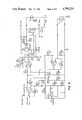
- FIG. 9is a schematic diagram of the circuit which is utilized twice in the preferred embodiment of our system, once as the probe controller and once as the chopper controller.
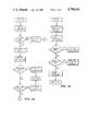
- FIG. 10is a flow diagram of the main loop of the control program of the preferred embodiment of our system.
- FIG. 11is a flow diagram of the chop algorithm of the control program of the preferred embodiment of our system.
- FIG. 12is a flow diagram of the thermopile temperature acquisition algorithm of the control program of the preferred embodiment of our system.
- FIG. 13is a flow diagram of the surface algorithm of the control program of the preferred embodiment of our system.
- FIG. 14is a flow diagram of the special functions mode algorithm of the control program of the preferred embodiment of our system.
- FIG. 15is a flow diagram of the algorithm of the control program of the preferred embodiment of our system which accomplishes 1-point offset calibration of the chopper.
- FIG. 16is a flow diagram of the algorithm of the control program of the preferred embodiment of our system which accomplishes 2-point calibration of the thermopile or chopper.
- FIG. 17is a flow diagram of the tympanic algorithm of the control program of the preferred embodiment of our system.
- the preferred embodiment of our systemincludes a probe unit 20 which mechanically mates with a chopper unit 22. Internal electronics of the probe and chopper units are electrically connected through a cord 24 which attaches to the rearward ends of the units.
- the probe unit 20has a cylindrical handle 26 adapted to be grasped by the hand of the user.
- a head assembly 28(FIGS. 2 and 6) extends from the forward end of the handle at an angle with respect thereto.
- the head assembly 28terminates in a probe 30 (FIGS. 2 and 6) which is covered by a disposable plastic speculum 32 (FIG. 7).
- the shielded probeis inserted into the external ear canal 34 (FIG. 6) of a patient in taking his or her temperature.
- the chopper unit 22has a generally rectangular, box-like outer configuration.
- An upwardly opening elongate recess 36extends along the top of the chopper unit 22 adjacent one side edge thereof.
- the recess 36receives and aligns the cylindrical handle 26 of the probe unit 20 so that the head assembly 28 thereof is inserted into a receptacle communicating with the recess 36. This positions the head assembly 28 as illustrated in FIG. 2 so that the forward terminal end of the probe 30 is adjacent a heated target 38 mounted at the bottom of the receptacle.
- FIG. 1Another upwardly opening rectangular cavity 40 (FIG. 1) formed in the top of the chopper unit 22 holds a plurality of disposable speculums 32 as illustrated in FIGS. 1 and 2.
- the speculumsare covered by a transparent door 42 (FIG. 1) which is hinged along one side edge to allow access to the speculums.
- a printed circuit board 44(FIG. 2) is mounted within the chopper unit 22 and serves as a carrier for the electronics illustrated in FIG. 8b.
- a permanent magnet 46closes a reed switch 48 (FIG. 8b) in the chopper unit to indicate that the two units are mated.
- the permanent magnet 46 and the reed switch 48are mounted at locations within the probe handle and chopper housing, respectively, so that they are physically adjacent when the probe handle is cradled in the chopper unit as illustrated in FIGS. 1-3.
- the chopper unit 22further includes a function key pad having keys 50 (FIG. 1) and a liquid crystal display 52 (FIGS. 1 and 5). This display indicates measured temperature and certain other functions of the system as described hereafter in greater detail.
- the probe unit 20also has an LED 54 (FIGS. 1 and 3) which is illuminated to indicate that a temperature reading has been completed.
- a manually actuable SCAN key 56 on the handle of the probe unitis depressed by the user's thumb to indicate that the probe 30 has been inserted into the patient's ear canal and thereby initiate sensing of infrared emissions therein.
- the charger unit 58 of the preferred embodiment of our systemincludes a rectangular outer housing with the power supply circuitry of FIG. 8c mounted therein.
- a cord 60connects the power supply to a standard 115 volt AC power source 62 such as a conventional wall outlet.
- the charger unit 58is configured to mechanically mate with the joined probe and chopper units.
- a permanent magnet 64(FIG. 8c) within the charger unit closes a reed switch 66 (FIG. 8b) in the chopper unit 22 to provide a signal indicative of the mated relationship.
- DC current from the charger unit 58is induced in the chopper unit 22 through a connectorless arrangement.
- a first coil 68(FIG.
- the charging circuitincludes a transformer 76 and a rectifier bridge 78. The transformer steps the 120 volt AC line current down to twelve volts.
- the twelve volt AC currentis rectified by the bridge 78 and filtered by a capacitor C1.
- the resulting nominal twelve volts DCis used to supply U1 which is an inverter with hystersis.
- This inverter U1has a feedback through a resistor R1, a capacitor C2 and a potentiometer R2 to cause oscillation at the resonant frequency of the coil 70 and capacitor 72 (FIG. 8b).
- the square wave output of the inverter U1is fed to a FET Q1 (FIG. 8c) that drives a coil L1, driving through current limitors in the form of a resistor R3 and a capacitor C3.
- the potentiometer R2is used to "tune" the circuit to provide the optimum current out to the battery.
- the probe 30 covered by the speculum 32is inserted into the ear canal approximately one-quarter of an inch for approximately one to two seconds to measure the temperature of the tympanic membrane 80 and the ear canal 34.
- the speculumpresents a clean, sanitary surface to the patient and also keeps the probe tip free of ear wax and hair.
- the speculum 32has a frontal, circular membrane 82 (FIG. 7) which is substantially transparent to infrared radiation in the seven to ten micron wavelength.
- the body 84 of the speculum 32has a generally frusto-conical shape and has a hollow interior.
- the thickness of the speculum body 84is substantially greater than that of the frontal membrane 82 in order to provide an adequate degree of structural rigidity.
- the frontal membrane 82 and body 84 of the speculumare made of a pliant plastic material which is substantially transparent to infrared radiation in the desired frequency range. Polyethylene or polypropylene may be used, for example.
- the body 84 of the speculumis configured and dimensioned so that it will squeeze over the frontal portion of the probe 30. The pliancy of the speculum allows it to deform somewhat upon insertion into the ear canal for added comfort.
- the probe 30(FIG. 7) is preferably made of a material with very low thermal conductivity, such as a PVC plastic.
- the probehas a hollow cylindrical base portion 86, an intermediate tubular portion 88 and a cylindrical tip portion 90.
- the head assembly 28 (FIG. 2) of the probe unitfurther includes a thermopile detector 92 which is embedded into a cylindrical metal housing 94.
- a metal tube 96has its rearward end secured to the center of the cylindrical housing 94 and acts as a waveguide for the infrared emissions which pass through the frontal membrane 82 of the speculum, through the center of the tube 96 to the frontal sensing region of the thermopile 92.
- One suitable thermopileis the Model 2M commercially available from Dexter Research located in Michigan.
- the cylindrical housing 94is preferably made of metal such as aluminum and has a central cylindrical bore 98 for receiving the cylindrical outer case of the thermopile 92.
- thermopileis preferably seated in thermal grease to insure thermal conductivity between the thermopile and the metal housing 94.
- a central aperture 100 also formed in the metal housing 94permits infrared radiation transmitted through the interior of the waveguide tube 96 to impinge upon the frontal sensor region of the thermopile 92.
- the tube 96is preferably made of brass and its interior walls are preferably plated with gold. Preferably there is a small air gap, for example .002 inches between the rearward end of the waveguide tube 96 and the frontal sensor region of the thermopile 92.
- the tube 96extends through the intermediate tubular portion 88 of the probe 30.
- thermopile 92fits within the cylindrical base portion 86 of the probe.
- a cylindrical backplate 102(FIG. 7) overlies the rearward surface of the thermopile 92 and also fits within the cylindrical base portion 86 of the probe 30.
- the backplate 102has a central hole 104 through which the leads 106 of the thermopile extend.
- the metal thermopile housing 94(FIG. 7) is heated to a predetermined precise temperature by resistors which are energized and controlled through the circuit of FIG. 9 as hereafter described in greater detail.
- the resistors 108fit snugly within holes 110 drilled through opposite sides of the thermopile housing.
- the resistorsmay also be packed in thermal grease to insure thermal conductivity between the thermopile housing and the resistors.
- the temperature of the thermopile housingis precisely controlled through a thermistor 112 (FIG. 7) which fits within a hole 114 drilled in the thermopile housing 94.
- the thermistormay be similarly packed in thermal grease.
- the thermistorforms part of the regulating circuit of FIG. 9 hereafter described in greater detail.
- the forward projecting leads of the resistors 108are connected in an annular groove (not illustrated) formed in the frontal surface of the thermopile housing 94.
- the rearward leads of the resistors 108 as well as the leads of the thermistor 112also extend through holes (not illustrated) in the cylindrical backplate 102.
- the construction of the target 38(FIG. 2) is illustrated in detail in FIG. 7. It includes a cylindrical member 116 preferably made of metal such as aluminum.
- the frontal side of the target member 116has a central, outwardly opening cylindrical cavity 118 formed therein.
- the target member surfaces, including the surfaces of the cavity 118have a black anodized finish which has an emissivity very near that of skin, i.e. .99 in the infrared wavelength of interest.
- a pair of heating resistors 120are snugly mounted within holes 122 which extend through opposite sides of the target member 116.
- An annular groove(not illustrated) extends around the frontal surface of the target member 116, outside of the cavity 118 and the forward leads of the resistors 120 extend in the groove and are connected in series.
- a thermistor 124snugly fits within a hole 126 in the target member 116.
- the resistors 120 and the thermistor 124are also preferably packed in thermal grease to insure thermal conductivity with the aluminum target member 116.
- the targetis heated to a precise predetermined temperature, such as 98° F. This temperature is precisely controlled by a circuit of the type illustrated in FIG. 9 which is identical to the separate circuit which controls the temperature of the thermopile housing 94.
- the target 38is situated in the chopper unit 22 such that the field of view of the thermopile is within the cavity 118 of the target when the probe unit is mated with the chopper unit as illustrated in FIG. 2.
- the forward end of the waveguide tube 96(FIG. 7) is positioned within, but does not touch, the walls of the cavity 118 of the target member 116.
- the bottom wall of the cavity 118is preferably concave.
- the speculum 32is removed from the probe.
- the speculum 32is illustrated in FIG. 7 merely to show its dimensional relationship with the probe 30.
- the chopper target 38is heated to a predetermined target reference temperature, e.g. 98° F.
- the thermopileis thereby calibrated to a temperature near the core body temperature. This approach yields higher accuracy than if the target were allowed to fluctuate with the ambient room temperature. Since the target is close to the body temperature, any changes in the gain of the thermopile 92 or its associated circuitry hereafter described will result in less error. Linearization of the output of the thermopile need not be as precise to attain high accuracy in the desired 95° F. to 102° F. range.
- the electronics of the probe unit 20are illustrated in functional block form.
- the thermistor 92 in the probe head assemblyis connected to an amplifier 128 which boosts the thermopile output to a voltage level suitable for inputing to the A/D converter 130 (FIG. 8b) in the chopper unit 22 through analog switch 132.
- Leads 134, 136 and 138 (FIG. 8a) from the LED 54, SCAN switch 56 and amplifier 128, respectively,are connected via cord 24 to leads 140, 142 and 144, respectively, of the chopper unit circuitry illustrated in FIG. 8b.
- a probe controller circuit 146(FIG.
- thermopile housing 94is used to maintain the thermopile housing 94 at a precise, predetermined ear canal reference temperature, preferably 98° F.
- a precise, predetermined ear canal reference temperaturepreferably 98° F.
- thermopile 92is a relative device which measures the energy level emitted by a target relative to the temperature of the reference. The thermopile therefore must be compensated for changes in the reference temperature.
- the output of the thermopileis not linear with temperature but behaves according to the following equation:
- Eis the thermopile output
- Kis a constant related to the sensitivity of the optical detector system
- T 2is the target temperature
- T 1is the reference temperature.
- thermopile temperatureBy keeping the thermopile temperature constant, no compensation for absolute reference temperature or changes in gain due to non-linearity have to be made.
- FIG. 9is a schematic diagram of one circuit suitable for use as the probe controller circuit 146.
- the output of the thermistor 112is applied to pin 6 of an amplifier U1D which amplifies the signal and provides an output on pin 7. This output is further amplified through amplifier U1A using resistors R1 and R3 for gain control and resistor R2 as an offset.
- the output of amplifier U1Dis also fed into amplifier U1B and is referenced against the input on pin 10.
- the input on pin 10is the voltage that represents the desired reference temperature. If the temperature is too high, the resistance of the thermistor 112 decreases. This causes a signal on pin 7 of the amplifier U1D to be more positive. This positive input into the amplifier U1B through pin 9 causes the signal on pin 8 to go more negative and decreases the current in the heater resistors 108.
- the absolute value of the desired thermopile housing reference temperatureis represented by the voltage from the arm of a potentiometer R15 (FIG. 9). This means that the supply voltage must be very stable.
- the supply voltagecomes from an amplifier U1C.
- the referenceis a Zener diode VR1 and the supply current to the reference is supplied through resistor R10.
- the amplifier U1Camplifies the voltage by the ratio of resistors R11 and R12. Since it is possible for the output of the amplifier U1C to be low, a diode DX and a resistor RX are used to "start" the circuit.
- the control deviceWhen a linear device such as a transistor is used to drive a heater element, the control device may have as much as one-half of the power lost in it. This might occur, for example, when there is an equal voltage across both the control device and the load. If a pulse with a variable duty cycle is used to drive the heater, there is very little loss in the driver because it has no current through it, or it has no voltage across it, and thus no power.
- the analog output of the control amplifier U1Bis used to control what is basically a voltage controlled multivibrator.
- the control voltage from the amplifier U1Bgoes through resistors R6 and R7 to the gate of a field effect transistor Q2 that has the load connected to its drain.
- a transistor Q1has a large value resistor R9, for example one megohm, connected from its base to its collector, and is used to start the switch cycle.
- resistor R9for example one megohm
- the transistor Q1Since the transistor Q1 is already conducting or near conducting, it will drive Q1 with the output from the collector of Q2, and Q2 will in turn drive the transistor Q1 so that both transistors are fully on.
- a capacitor C4 and a resistor R8have discharged a capacitor to the point that the transistor Q1 will no longer hold a transistor Q2 on, the drain of the transistor Q2 will go positive and turn the transistor Q1 off.
- a diode CR2is used to restore the charge on the capacitor C4.
- the diode CR1pulls the positive voltage on a capacitor C3 to near ground. Then, when the transistor Q2 is off, the time constant provided by the resistor R6 and the capacitor C3 starts the cycle again.
- the diode CR3is used to hold the gate of the transistor Q2 low and inhibit operation when the output of the control amplifier U1B is low.
- FIG. 8billustrates the circuitry of the chopper unit 22 in block diagram form.
- the thermistor 124 and the heating resistors 120 in the target 38are connected to a chopper controller circuit 148.
- One suitable circuit for the chopper controlleris illustrated in FIG. 9. In the preferred embodiment of our system, the circuit of FIG. 9 is used twice, once in the probe controller and the second time in the chopper controller. In one case the thermistor 112 and resistors 108 are the input and control devices, respectively. In the other case, the thermistor 124 and the resistors 120 are the input and control devices, respectively.
- the probe controller circuit 146 and the chopper controller circuit 148both function in the same manner.
- the chopper controller circuitis used to heat, regulate and maintain the aluminum target member 116 to a predetermined reference temperature, preferably 98° F. This permits the thermopile in the probe unit to be calibrated to a temperature near the core body temperature. As already indicated, this approach yields higher accuracy than if the target were allowed to fluctuate with the ambient room temperature.
- the circuitry of the chopper unit 22further includes an amplifier 150 which is connected to the chopper controller circuit 148 and has an output corresponding to the chopper target temperature. This output is inputted to a microcomputer 152 through the analog switch 132 and the A/D converter 130.
- the A/D converter 130has a voltage reference 154.
- the microcomputermay be MOTOROLA type 146805G having 2K bytes of ROM and 128 bytes of RAM.
- the aforementioned microcomputeris preferably operated with a 2 MHz crystal 156.
- the A/D converter 130may be a 13 bit INTERSIL ICL7 109 device.
- the analog switch 132may be a type CD4053 analog multiplexer which switches anyone of the following three analog inputs under the control of the microcomputer 152: thermopile signal on lead 144, chopper target signal on lead 158 and a battery condition on lead 160.
- the microcomputer 152(FIG. 8b) drives the display 52 through a driver circuit 162.
- this circuitmay be a type of COP472 chip.
- the keys 50are in the form of a three position pad which is connected to the microcomputer 152 and is used to select one of four functions.
- the display 52(FIG. 8b)
- the key pad 50 and SCAN key 56may be manually actuated to select one of the following functions:
- the microcomputer 152is connected to an EEPROM 164 (FIG. 8b) which is used to store calibration data.
- This deviceis a 16 ⁇ 16 bit electrically erasable programmable read only memory.
- this partmay be a type NMC9306 chip.
- the microcomputer 152is also connected to an audio indicator 166 (FIG. 8b) which may take the form of a piezoelectric buzzer. This buzzer alerts the user when (1) any key is depressed; (2) the tympanic algorithm is completed and (3) during various situations when an alarm is required.
- the reed switch 66provides a signal to the microcomputer 152 via security input line 168 to protect against unauthorized removal of the mated probe/chopper units from the charger unit 58. When the security system is armed, the user must press a plurality of the keys 50 in a certain sequence to disarm the system, otherwise the system will not operate to provide temperature measurements and the audio alarm will be sounded.
- the circuitry of the chopper unit illustrated in FIG. 8bfurther includes a step-up circuit 170 which boosts the battery voltage from a nominal 2.4 volts to a nominal 7 volts, a voltage regulator 172 which regulates this voltage to approximately 5 volts, and a voltage converter 174 which converts the 5 volts to -5 volts.
- FIGS. 10-17are flow diagrams of the various aspects of the control program which enable it to perform the system functions.
- the sequence of events which takes place in order for the system to determine a patient's core temperature from infrared emissions in his or her external ear canalis as follows: (1) calibration through chopping during the time that the probe and chopper units are mated; (2) removal of the probe unit from the chopper unit; (3) insertion of the probe into a sanitary speculum; (4) positioning of the speculum-covered probe in the external ear canal; (5) tympanic algorhithm execution and display; (6) removal of the probe from the external ear canal and discarding of the speculum; and (7) re-mating of the probe and chopper units and re-initiation of recalibration through chopping.
- the probe unitPrior to taking a patient's temperature, the probe unit is cradled in the chopper unit. During this time, the microcomputer continuously samples the key pad, checks the battery condition, and calibrates the thermopile against the chopper reference target. The procedure to calibrate or chop involves the following. First, the microcomputer determines the chopper target temperature. Then the microcomputer determines the thermopile output level which corresponds to that temperature. Finally, the microcomputer determines whether the probe unit has been chopping for a requisite minimum time period to insure stability. The calibration or chopping which has just been described is a regular system function which is performed each time the probe unit is replaced on the chopper unit. This is to be distinguished from factory calibration in which the reference temperatures of the probe controller and chopper controller are established and calibration data is programmed into the EEPROM. This factory calibration is set forth in the flow diagrams of FIGS. 15 and 16.
- the microcomputerIn the standard calibration or chopping mode, the microcomputer repeatedly determines the digital equivalent of the thermopile output while the thermopile is sensing infrared radiations from the chopper target.
- the chopper controller circuit 148maintains the temperature of the target at a very precise reference temperature, preferably 98° F., with a high degree of accuracy. Therefore, the microcomputer, in the standard calibration mode, is acquiring the digital representation of the thermopile output level for a known temperature, i.e. 98° F. Each time this digital equivalent is acquired, it is stored.
- the microcomputer unitdetects this by sensing of the opening of the reed switch 48 (FIG. 8b). If the requisite, preprogrammed minimum time period for chopping has not been met, the microcomputer sounds the audio alarm 166 and the user must replace the probe unit onto the chopper unit. If the requisite minimum time period for chopping has elapsed, the microcomputer starts acquiring the thermopile output level at the rate of approximately seven times per second and stores the maximum reading.
- thermopile temperatureThe manner of acquiring a thermopile temperature is as follows. The output level of the thermopile while looking at the target to be measured is acquired. From this the output level stored during the last chop is subtracted. The difference is multiplied by the gain of the thermopile to arrive at a temperature difference of the target relative to the chopper target. To this number is added the chopper target temperature taken during the last chop.
- a disposable speculumis inserted over the tip of the probe.
- the userthen inserts the speculum covered probe into the external ear canal using moderate pressure.
- the userthen actuates the SCAN key to alert the microcomputer that the tympanic algorithm should commence. This step must be accomplished within ten seconds of removal of the probe unit from the chopper unit. If not completed within ten seconds, the microcomputer will sound the audio alarm.
- the probe unitmust then be replaced on the chopper unit to allow adequate recalibration before the system will again be in condition for taking a tympanic membrane temperature reading. This ten second time limit prevents excessive drift while the probe unit is removed from the chopper.
- thermopile temperature acquisitionsare performed lasting for a period of approximately one second.
- the maximum reading from the beginning of the removal of the probe unit from the chopper unitis displayed as the tympanic temperature.
- the LED 56 (FIG. 1) on the probe handleis illuminated and the audio indicator is energized to signal completion of the temperature reading process. The LED illumination and audio signal are discontinued.
- the speculum-covered probeis removed from the external ear canal.
- the speculumis removed and disposed of and the probe unit is replaced in the chopper unit.
- the systemthen goes through its standard calibration process again until the next function is initiated by depression of one or more of the keys 50 or removal of the probe unit.
Landscapes
- Physics & Mathematics (AREA)
- General Physics & Mathematics (AREA)
- Spectroscopy & Molecular Physics (AREA)
- Measuring And Recording Apparatus For Diagnosis (AREA)
Abstract
Description
E=K(T.sub.2 -T.sub.1).sup.4
Claims (13)
Priority Applications (1)
| Application Number | Priority Date | Filing Date | Title |
|---|---|---|---|
| US07/031,164US4790324A (en) | 1984-10-23 | 1987-03-25 | Method and apparatus for measuring internal body temperature utilizing infrared emissions |
Applications Claiming Priority (3)
| Application Number | Priority Date | Filing Date | Title |
|---|---|---|---|
| US06/663,769US4602642A (en) | 1984-10-23 | 1984-10-23 | Method and apparatus for measuring internal body temperature utilizing infrared emissions |
| US86957886A | 1986-06-02 | 1986-06-02 | |
| US07/031,164US4790324A (en) | 1984-10-23 | 1987-03-25 | Method and apparatus for measuring internal body temperature utilizing infrared emissions |
Related Parent Applications (1)
| Application Number | Title | Priority Date | Filing Date |
|---|---|---|---|
| US86957886AContinuation | 1984-10-23 | 1986-06-02 |
Publications (1)
| Publication Number | Publication Date |
|---|---|
| US4790324Atrue US4790324A (en) | 1988-12-13 |
Family
ID=27363807
Family Applications (1)
| Application Number | Title | Priority Date | Filing Date |
|---|---|---|---|
| US07/031,164Expired - LifetimeUS4790324A (en) | 1984-10-23 | 1987-03-25 | Method and apparatus for measuring internal body temperature utilizing infrared emissions |
Country Status (1)
| Country | Link |
|---|---|
| US (1) | US4790324A (en) |
Cited By (121)
| Publication number | Priority date | Publication date | Assignee | Title |
|---|---|---|---|---|
| US4900162A (en)* | 1989-03-20 | 1990-02-13 | Ivac Corporation | Infrared thermometry system and method |
| WO1990005902A1 (en)* | 1988-11-01 | 1990-05-31 | Diatek, Inc. | Probe assembly for infrared thermometer |
| US4932789A (en)* | 1988-04-12 | 1990-06-12 | Citizen Watch Co., Ltd. | Radiation clinical thermometer |
| DE3910749A1 (en)* | 1989-04-03 | 1990-10-04 | Hellige Gmbh | Method and device for the non-invasive monitoring of physiological parameters |
| US4993419A (en)* | 1988-12-06 | 1991-02-19 | Exergen Corporation | Radiation detector suitable for tympanic temperature measurement |
| US5012813A (en)* | 1988-12-06 | 1991-05-07 | Exergen Corporation | Radiation detector having improved accuracy |
| USD317414S (en) | 1989-05-08 | 1991-06-11 | Ivac Corporation | Handheld infrared thermometer |
| USD318812S (en) | 1989-05-08 | 1991-08-06 | Ivac Corporation | Disposable speculum for an infrared thermometer |
| EP0446788A1 (en)* | 1990-03-12 | 1991-09-18 | Ivac Corporation | System for temperature determination and calibration in a biomedical thermometer |
| USD321487S (en) | 1989-04-24 | 1991-11-12 | Diatek Incorporated | Infrared thermometer |
| US5066142A (en)* | 1990-03-08 | 1991-11-19 | Ivac Corporation | Protective apparatus for a biomedical probe |
| US5079421A (en)* | 1990-04-19 | 1992-01-07 | Inomet, Inc. | Invasive FTIR blood constituent testing |
| US5088834A (en)* | 1990-08-24 | 1992-02-18 | Thermoscan Inc. | Unitary probe cover |
| EP0472490A1 (en)* | 1990-08-24 | 1992-02-26 | Thermoscan Inc. | Unitary probe cover |
| US5100018A (en)* | 1990-10-11 | 1992-03-31 | Ivac Corporation | Probe cover dispenser |
| US5115133A (en)* | 1990-04-19 | 1992-05-19 | Inomet, Inc. | Testing of body fluid constituents through measuring light reflected from tympanic membrane |
| US5127742A (en)* | 1991-04-19 | 1992-07-07 | Thermoscan Inc. | Apparatus and method for temperature measurement by radiation |
| USD329395S (en) | 1990-09-13 | 1992-09-15 | Thermoscan Inc. | Radiation thermometer |
| USD329396S (en) | 1990-09-13 | 1992-09-15 | Thermoscan Inc. | Radiation thermometer |
| US5150969A (en)* | 1990-03-12 | 1992-09-29 | Ivac Corporation | System and method for temperature determination and calibration in a biomedical probe |
| US5159936A (en)* | 1990-08-17 | 1992-11-03 | Mark Yelderman | Noncontact infrared tympanic thermometer |
| US5163418A (en)* | 1989-09-19 | 1992-11-17 | Thermoscan Inc. | Speculum cover |
| US5199436A (en)* | 1988-12-06 | 1993-04-06 | Exergen Corporation | Radiation detector having improved accuracy |
| USD334626S (en) | 1990-09-18 | 1993-04-06 | Ivac Corporation | Combined medical instrument base and probe cover dispenser |
| US5213099A (en)* | 1991-09-30 | 1993-05-25 | The United States Of America As Represented By The Secretary Of The Air Force | Ear canal pulse/oxygen saturation measuring device |
| US5232284A (en)* | 1988-04-12 | 1993-08-03 | Citizen Watch Co., Ltd. | Radiation clinical thermometer |
| US5246292A (en)* | 1992-05-28 | 1993-09-21 | Eli Gal | Temperature measurement apparatus |
| US5271407A (en)* | 1988-12-06 | 1993-12-21 | Exergen Corporation | Radiation detector suitable for tympanic temperature measurement |
| USRE34507E (en)* | 1988-04-12 | 1994-01-11 | Citizen Watch Co., Ltd. | Radiation clinical thermometer |
| USRE34599E (en)* | 1988-11-01 | 1994-05-03 | Diatek Incorporated | Disposable probe cover assembly for medical thermometer |
| US5319202A (en)* | 1990-08-01 | 1994-06-07 | Exergen Corporation | Radiation detector with remote temperature reference |
| US5340215A (en)* | 1990-12-29 | 1994-08-23 | Omron Corporation | Radiant-energy clinical thermometer |
| US5445158A (en)* | 1988-12-06 | 1995-08-29 | Exergen Corporation | Radiation detector probe |
| WO1995022928A1 (en)* | 1994-02-28 | 1995-08-31 | Economation, Inc. | Infrared tympanic thermometer |
| US5458121A (en)* | 1992-09-17 | 1995-10-17 | Terumo Kabushiki Kaisha | Clinical thermometer |
| US5479931A (en)* | 1993-11-18 | 1996-01-02 | Thermoscan, Inc. | IR thermometer |
| US5482183A (en)* | 1994-09-30 | 1996-01-09 | Beal; Jeff R. | Heater and dispenser for vials |
| US5528041A (en)* | 1990-08-01 | 1996-06-18 | Exergen Corporation | Radiation detector with remote temperature reference |
| US5614716A (en)* | 1996-04-26 | 1997-03-25 | Infratemp, Inc. | Alternating current method and apparatus for ambient temperature compensation for modulated energy sensors |
| US5650624A (en)* | 1995-04-13 | 1997-07-22 | Engelhard Sensor Technologies, Inc. | Passive infrared analysis gas sensor |
| US5653238A (en)* | 1988-12-06 | 1997-08-05 | Exergen Corporation | Radiation detector probe |
| US5653537A (en)* | 1995-03-17 | 1997-08-05 | Ircon, Inc. | Non-contacting infrared temperature thermometer detector apparatus |
| US5666956A (en)* | 1996-05-20 | 1997-09-16 | Buchert; Janusz Michal | Instrument and method for non-invasive monitoring of human tissue analyte by measuring the body's infrared radiation |
| US5721430A (en)* | 1995-04-13 | 1998-02-24 | Engelhard Sensor Technologies Inc. | Passive and active infrared analysis gas sensors and applicable multichannel detector assembles |
| US5725308A (en)* | 1994-12-23 | 1998-03-10 | Rtd Technology, Inc. | Quick registering thermometer |
| US5812270A (en)* | 1997-09-17 | 1998-09-22 | Ircon, Inc. | Window contamination detector |
| US5823966A (en)* | 1997-05-20 | 1998-10-20 | Buchert; Janusz Michal | Non-invasive continuous blood glucose monitoring |
| US5833367A (en) | 1996-11-12 | 1998-11-10 | Trutek, Inc. | Tympanic thermometer probe cover |
| US5857775A (en)* | 1995-09-05 | 1999-01-12 | Tyco Group S.A.R.L. | Thermometer probe having a watertight seal |
| US5872362A (en)* | 1990-08-01 | 1999-02-16 | Exergen Corporation | Radiation detector with remote temperature reference |
| US5871449A (en)* | 1996-12-27 | 1999-02-16 | Brown; David Lloyd | Device and method for locating inflamed plaque in an artery |
| US5893833A (en)* | 1995-06-06 | 1999-04-13 | Exergen Corporation | Axillary infrared thermometer and cover therefor |
| US5967992A (en) | 1998-06-03 | 1999-10-19 | Trutex, Inc. | Radiometric temperature measurement based on empirical measurements and linear functions |
| US5991700A (en)* | 1997-10-15 | 1999-11-23 | Sherwood Services, A.G. | EMI stability indicator for tympanic thermometer |
| US6001066A (en) | 1997-06-03 | 1999-12-14 | Trutek, Inc. | Tympanic thermometer with modular sensing probe |
| US6002482A (en)* | 1996-01-17 | 1999-12-14 | Spectrx, Inc. | Disposable calibration device |
| US6030117A (en) | 1996-11-12 | 2000-02-29 | Trutek, Inc. | Tympanic thermometer probe cover |
| US6065866A (en)* | 1996-04-02 | 2000-05-23 | Braun Aktiengesellschaft | Method of calibrating a radiation thermometer |
| US6123454A (en) | 1999-06-11 | 2000-09-26 | Trutek, Inc. | Tympanic thermometer disposable probe cover with further stretching prevention structure |
| US6146015A (en)* | 1998-10-05 | 2000-11-14 | Micro Weiss Electronics | Fast response digital thermometer |
| US6192268B1 (en)* | 1997-11-14 | 2001-02-20 | Citizen Watch Co. Ltd. | Radiation thermometer |
| US6192734B1 (en) | 1996-01-17 | 2001-02-27 | Spectrx, Inc | Disposable calibration target |
| US6219573B1 (en) | 1989-04-14 | 2001-04-17 | Exergen Corporation | Radiation detector probe |
| WO2001027580A1 (en)* | 1999-10-12 | 2001-04-19 | Simon Dotan | Electronic thermometer with preheating |
| US6224256B1 (en) | 1998-06-18 | 2001-05-01 | Harry Bala | Cover for medical probe |
| US6226541B1 (en)* | 1996-01-17 | 2001-05-01 | Spectrx, Inc. | Apparatus and method for calibrating measurement systems |
| US6238088B1 (en)* | 1999-01-12 | 2001-05-29 | Norm Pacific Automation Corp. | Disposable cap for instant thermometer measuring probe |
| US6332090B1 (en)* | 1990-03-08 | 2001-12-18 | Alaris Medical Systems, Inc. | Thermally isolated probe for biomedical apparatus and method of communicating energy there through |
| US6336742B2 (en) | 1997-08-08 | 2002-01-08 | Omron Corporation | Clinical thermometer for receiving infrared radiation from a human eardrum |
| US6390671B1 (en) | 2000-04-28 | 2002-05-21 | K-Jump Health Co., Ltd. | Probe cover with film insert |
| US20020068876A1 (en)* | 1999-11-24 | 2002-06-06 | Exergen Corporation | Temporal thermometer disposable cap |
| US20020077564A1 (en)* | 1996-07-29 | 2002-06-20 | Farallon Medsystems, Inc. | Thermography catheter |
| US6435711B1 (en) | 1998-09-15 | 2002-08-20 | Jonathan Gerlitz | Infrared ear thermometer |
| US6475159B1 (en) | 1995-09-20 | 2002-11-05 | S. Ward Casscells | Method of detecting vulnerable atherosclerotic plaque |
| US6514214B2 (en) | 2001-02-13 | 2003-02-04 | Scimed Life Systems, Inc. | Intravascular temperature sensor |
| US6609823B2 (en)* | 2000-05-23 | 2003-08-26 | Braun Gmbh | Infrared radiation thermometer with variable exterior probe head for conforming to body cavity |
| US6615071B1 (en) | 1995-09-20 | 2003-09-02 | Board Of Regents, The University Of Texas System | Method and apparatus for detecting vulnerable atherosclerotic plaque |
| US20030169802A1 (en)* | 2001-07-06 | 2003-09-11 | Min-Ying Chen | Method of stabilizing an infrared clinical thermometer and the apparatus thereof |
| US6694181B2 (en) | 2001-02-12 | 2004-02-17 | Scimed Life Systems, Inc. | Methods and devices for detecting vulnerable plaque |
| US20040073132A1 (en)* | 2002-05-07 | 2004-04-15 | Tracy Maahs | Systems and methods for detecting vulnerable plaque |
| US20040114659A1 (en)* | 2002-10-11 | 2004-06-17 | Welch Allyn, Inc. | Thermometry probe calibration method |
| US6763261B2 (en) | 1995-09-20 | 2004-07-13 | Board Of Regents, The University Of Texas System | Method and apparatus for detecting vulnerable atherosclerotic plaque |
| US20040152991A1 (en)* | 1998-09-11 | 2004-08-05 | Exergen Corporation | Temporal artery temperature detector |
| EP1454583A3 (en)* | 1999-06-11 | 2004-11-17 | Omron Corporation | Ear type clinical thermometer |
| US20040240516A1 (en)* | 2002-12-12 | 2004-12-02 | James Harr | Thermal tympanic thermometer tip |
| US20050049471A1 (en)* | 2003-08-25 | 2005-03-03 | Aceti John Gregory | Pulse oximetry methods and apparatus for use within an auditory canal |
| US20050059870A1 (en)* | 2003-08-25 | 2005-03-17 | Aceti John Gregory | Processing methods and apparatus for monitoring physiological parameters using physiological characteristics present within an auditory canal |
| US6882873B2 (en) | 1996-01-17 | 2005-04-19 | Respironics, Inc. | Method and system for determining bilirubin concentration |
| US20050083993A1 (en)* | 2003-10-21 | 2005-04-21 | Chin-Chih Hsieh | Electronic ear thermometer with multiple measurement and memory function |
| US6958039B2 (en) | 2003-05-02 | 2005-10-25 | Oculir, Inc. | Method and instruments for non-invasive analyte measurement |
| US6968222B2 (en) | 2003-05-02 | 2005-11-22 | Oculir, Inc. | Methods and device for non-invasive analyte measurement |
| US6975892B2 (en) | 2003-10-21 | 2005-12-13 | Oculir, Inc. | Methods for non-invasive analyte measurement from the conjunctiva |
| WO2006009585A1 (en) | 2004-06-18 | 2006-01-26 | Advanced Monitors Corporation | Medical body core thermometer |
| US7047148B1 (en)* | 2000-07-05 | 2006-05-16 | Cirrus Logic, Inc. | Indirect techniques for measuring 1/f noise |
| US20060222048A1 (en)* | 1997-06-24 | 2006-10-05 | Francesco Pompei | Ambient and perfusion normalized temperature detector |
| US7123968B1 (en) | 1996-09-20 | 2006-10-17 | The Board Of Regents Of The University Of Texas System | Heat treatment of inflamed tissue |
| US20060239332A1 (en)* | 2002-12-12 | 2006-10-26 | Sherwood Services Ag | Thermal tympanic thermometer |
| US20070067118A1 (en)* | 2005-09-19 | 2007-03-22 | Cooper Kerry J | Rechargeable food thermometer |
| US20070248141A1 (en)* | 2006-04-21 | 2007-10-25 | Sherwood Services Ag | Infrared thermometer and probe cover thereof |
| US20070263698A1 (en)* | 2006-05-09 | 2007-11-15 | Kevin Lin | Probe cover for ear thermometer |
| US20070268954A1 (en)* | 2006-05-19 | 2007-11-22 | Sherwood Services Ag | Portable test apparatus for radiation-sensing thermometer |
| US20070268952A1 (en)* | 2006-05-19 | 2007-11-22 | Sherwood Services Ag | Thermometer calibration by immersion in non-electrically conductive liquid |
| US20080084911A1 (en)* | 2006-10-06 | 2008-04-10 | Sherwood Services Ag | Anti-Theft System for Thermometer |
| US20080112464A1 (en)* | 2006-10-06 | 2008-05-15 | Sherwood Services Ag | Automatic Activating System for Thermometer |
| US7426409B2 (en) | 1999-06-25 | 2008-09-16 | Board Of Regents, The University Of Texas System | Method and apparatus for detecting vulnerable atherosclerotic plaque |
| US7478946B2 (en) | 2003-01-06 | 2009-01-20 | Covidien Ag | Probe cover cassette with improved probe cover support |
| US7484887B2 (en) | 2003-02-20 | 2009-02-03 | Ysis Incorporated | Digitally modified resistive output for a temperature sensor |
| US7507019B2 (en) | 2006-05-19 | 2009-03-24 | Covidien Ag | Thermometer calibration |
| US20090116540A1 (en)* | 2006-10-11 | 2009-05-07 | Vincent Weng | Probe cover for ear thermometer |
| US7549792B2 (en) | 2006-10-06 | 2009-06-23 | Covidien Ag | Electronic thermometer with selectable modes |
| US7556424B2 (en) | 2006-05-19 | 2009-07-07 | Covidien Ag | Tympanic thermometer prove cover cassette and holder |
| US20090175317A1 (en)* | 2008-01-04 | 2009-07-09 | Aviton Care Limited | Intelligent illumination thermometer |
| US7603166B2 (en) | 1996-09-20 | 2009-10-13 | Board Of Regents University Of Texas System | Method and apparatus for detection of vulnerable atherosclerotic plaque |
| US20090257469A1 (en)* | 2008-04-09 | 2009-10-15 | Jones Mike N | Infrared thermometer |
| US7686506B2 (en) | 2003-01-06 | 2010-03-30 | Covidien Ag | Stackable tympanic thermometer probe cover cassette |
| US20110158283A1 (en)* | 2009-12-31 | 2011-06-30 | Welch Allyn, Inc. | Temperature-measurement probe |
| EP2437039A2 (en) | 2010-09-30 | 2012-04-04 | Medisim Ltd. | Ergonomic hand held thermometer |
| US8274273B2 (en) | 2008-03-07 | 2012-09-25 | Milwaukee Electric Tool Corporation | Test and measurement device with a pistol-grip handle |
| US9299240B2 (en) | 2013-02-27 | 2016-03-29 | Welch Allyn, Inc. | Anti-loss for medical devices |
| US10342446B2 (en) | 2011-11-30 | 2019-07-09 | Welch Allyn, Inc. | Thermal powered medical device |
| US20190242753A1 (en)* | 2018-02-08 | 2019-08-08 | Famidoc Technology Co., Ltd | Ir thermometer for magnetic induction identification probe cap |
Citations (11)
| Publication number | Priority date | Publication date | Assignee | Title |
|---|---|---|---|---|
| US3282106A (en)* | 1963-01-28 | 1966-11-01 | Barnes Eng Co | Method of measuring body temperature |
| US3348408A (en)* | 1965-04-01 | 1967-10-24 | Barnes Eng Co | Reference source for calibration of thermographic instruments |
| US3491596A (en)* | 1967-10-02 | 1970-01-27 | Vito Charles P De | Temperature sensing device |
| US3507153A (en)* | 1968-07-12 | 1970-04-21 | Leeds & Northrup Co | Tympanic membrane thermometer |
| US3581570A (en)* | 1967-09-05 | 1971-06-01 | Garrett Corp | Thermal radiation sensor |
| US3949740A (en)* | 1973-08-23 | 1976-04-13 | Products International Marketing | Disposable speculum for tympanic thermometer |
| US4183248A (en)* | 1978-08-08 | 1980-01-15 | Rwb Labs | Fast response electronic thermometer probe |
| US4433924A (en)* | 1981-09-18 | 1984-02-28 | Honeywell Inc. | Thermal reference apparatus |
| US4493564A (en)* | 1982-09-27 | 1985-01-15 | Saul Epstein | Clinical instrument for measuring pulse rate and body temperature |
| US4566808A (en)* | 1983-02-16 | 1986-01-28 | Exergen Corporation | Scanning radiation detector |
| US4634294A (en)* | 1979-09-12 | 1987-01-06 | Raytek, Inc. | Hand-held digital temperature measuring instrument |
- 1987
- 1987-03-25USUS07/031,164patent/US4790324A/ennot_activeExpired - Lifetime
Patent Citations (11)
| Publication number | Priority date | Publication date | Assignee | Title |
|---|---|---|---|---|
| US3282106A (en)* | 1963-01-28 | 1966-11-01 | Barnes Eng Co | Method of measuring body temperature |
| US3348408A (en)* | 1965-04-01 | 1967-10-24 | Barnes Eng Co | Reference source for calibration of thermographic instruments |
| US3581570A (en)* | 1967-09-05 | 1971-06-01 | Garrett Corp | Thermal radiation sensor |
| US3491596A (en)* | 1967-10-02 | 1970-01-27 | Vito Charles P De | Temperature sensing device |
| US3507153A (en)* | 1968-07-12 | 1970-04-21 | Leeds & Northrup Co | Tympanic membrane thermometer |
| US3949740A (en)* | 1973-08-23 | 1976-04-13 | Products International Marketing | Disposable speculum for tympanic thermometer |
| US4183248A (en)* | 1978-08-08 | 1980-01-15 | Rwb Labs | Fast response electronic thermometer probe |
| US4634294A (en)* | 1979-09-12 | 1987-01-06 | Raytek, Inc. | Hand-held digital temperature measuring instrument |
| US4433924A (en)* | 1981-09-18 | 1984-02-28 | Honeywell Inc. | Thermal reference apparatus |
| US4493564A (en)* | 1982-09-27 | 1985-01-15 | Saul Epstein | Clinical instrument for measuring pulse rate and body temperature |
| US4566808A (en)* | 1983-02-16 | 1986-01-28 | Exergen Corporation | Scanning radiation detector |
Non-Patent Citations (2)
| Title |
|---|
| J. W. Moore & R. S. Newbower, "Noncontact Tympanic Thermometer", Sep. 1978-Medical & Biological Engineering & Computing, pp. 580-584. |
| J. W. Moore & R. S. Newbower, Noncontact Tympanic Thermometer , Sep. 1978 Medical & Biological Engineering & Computing, pp. 580 584.* |
Cited By (182)
| Publication number | Priority date | Publication date | Assignee | Title |
|---|---|---|---|---|
| US5024533A (en)* | 1988-04-12 | 1991-06-18 | Citizen Watch Co., Ltd. | Radiation clinical thermometer |
| US4932789A (en)* | 1988-04-12 | 1990-06-12 | Citizen Watch Co., Ltd. | Radiation clinical thermometer |
| US5232284A (en)* | 1988-04-12 | 1993-08-03 | Citizen Watch Co., Ltd. | Radiation clinical thermometer |
| USRE34507E (en)* | 1988-04-12 | 1994-01-11 | Citizen Watch Co., Ltd. | Radiation clinical thermometer |
| WO1990005902A1 (en)* | 1988-11-01 | 1990-05-31 | Diatek, Inc. | Probe assembly for infrared thermometer |
| USRE34599E (en)* | 1988-11-01 | 1994-05-03 | Diatek Incorporated | Disposable probe cover assembly for medical thermometer |
| US20040122338A1 (en)* | 1988-12-06 | 2004-06-24 | Exergen Corporation | Radiation detector probe |
| US6047205A (en)* | 1988-12-06 | 2000-04-04 | Exergen Corporation | Radiation detector probe |
| US5012813A (en)* | 1988-12-06 | 1991-05-07 | Exergen Corporation | Radiation detector having improved accuracy |
| US5199436A (en)* | 1988-12-06 | 1993-04-06 | Exergen Corporation | Radiation detector having improved accuracy |
| US20060062274A1 (en)* | 1988-12-06 | 2006-03-23 | Exergen Corporation | Radiation detector probe |
| US5271407A (en)* | 1988-12-06 | 1993-12-21 | Exergen Corporation | Radiation detector suitable for tympanic temperature measurement |
| US5653238A (en)* | 1988-12-06 | 1997-08-05 | Exergen Corporation | Radiation detector probe |
| US4993419A (en)* | 1988-12-06 | 1991-02-19 | Exergen Corporation | Radiation detector suitable for tympanic temperature measurement |
| US5445158A (en)* | 1988-12-06 | 1995-08-29 | Exergen Corporation | Radiation detector probe |
| US4900162A (en)* | 1989-03-20 | 1990-02-13 | Ivac Corporation | Infrared thermometry system and method |
| EP0391128A1 (en)* | 1989-03-20 | 1990-10-10 | Ivac Corporation | Infrared thermometry system and method |
| DE3910749A1 (en)* | 1989-04-03 | 1990-10-04 | Hellige Gmbh | Method and device for the non-invasive monitoring of physiological parameters |
| US6219573B1 (en) | 1989-04-14 | 2001-04-17 | Exergen Corporation | Radiation detector probe |
| USD321487S (en) | 1989-04-24 | 1991-11-12 | Diatek Incorporated | Infrared thermometer |
| USD317414S (en) | 1989-05-08 | 1991-06-11 | Ivac Corporation | Handheld infrared thermometer |
| USD318812S (en) | 1989-05-08 | 1991-08-06 | Ivac Corporation | Disposable speculum for an infrared thermometer |
| US5163418A (en)* | 1989-09-19 | 1992-11-17 | Thermoscan Inc. | Speculum cover |
| US6332090B1 (en)* | 1990-03-08 | 2001-12-18 | Alaris Medical Systems, Inc. | Thermally isolated probe for biomedical apparatus and method of communicating energy there through |
| US5066142A (en)* | 1990-03-08 | 1991-11-19 | Ivac Corporation | Protective apparatus for a biomedical probe |
| EP0446788A1 (en)* | 1990-03-12 | 1991-09-18 | Ivac Corporation | System for temperature determination and calibration in a biomedical thermometer |
| US5150969A (en)* | 1990-03-12 | 1992-09-29 | Ivac Corporation | System and method for temperature determination and calibration in a biomedical probe |
| US5146091A (en)* | 1990-04-19 | 1992-09-08 | Inomet, Inc. | Body fluid constituent measurement utilizing an interference pattern |
| US5079421A (en)* | 1990-04-19 | 1992-01-07 | Inomet, Inc. | Invasive FTIR blood constituent testing |
| US5115133A (en)* | 1990-04-19 | 1992-05-19 | Inomet, Inc. | Testing of body fluid constituents through measuring light reflected from tympanic membrane |
| US5179951A (en)* | 1990-04-19 | 1993-01-19 | Inomet, Inc. | Blood constituent measurement |
| US6617581B2 (en) | 1990-08-01 | 2003-09-09 | Exergen Corporation | Radiation detector with remote temperature reference |
| US5872362A (en)* | 1990-08-01 | 1999-02-16 | Exergen Corporation | Radiation detector with remote temperature reference |
| US6423970B1 (en) | 1990-08-01 | 2002-07-23 | Exergen Corporation | Radiation detector with remote temperature reference |
| US5319202A (en)* | 1990-08-01 | 1994-06-07 | Exergen Corporation | Radiation detector with remote temperature reference |
| US5528041A (en)* | 1990-08-01 | 1996-06-18 | Exergen Corporation | Radiation detector with remote temperature reference |
| US5159936A (en)* | 1990-08-17 | 1992-11-03 | Mark Yelderman | Noncontact infrared tympanic thermometer |
| US5088834A (en)* | 1990-08-24 | 1992-02-18 | Thermoscan Inc. | Unitary probe cover |
| EP0472490A1 (en)* | 1990-08-24 | 1992-02-26 | Thermoscan Inc. | Unitary probe cover |
| USD329395S (en) | 1990-09-13 | 1992-09-15 | Thermoscan Inc. | Radiation thermometer |
| USD329396S (en) | 1990-09-13 | 1992-09-15 | Thermoscan Inc. | Radiation thermometer |
| USD334626S (en) | 1990-09-18 | 1993-04-06 | Ivac Corporation | Combined medical instrument base and probe cover dispenser |
| US5100018A (en)* | 1990-10-11 | 1992-03-31 | Ivac Corporation | Probe cover dispenser |
| US5340215A (en)* | 1990-12-29 | 1994-08-23 | Omron Corporation | Radiant-energy clinical thermometer |
| US5127742A (en)* | 1991-04-19 | 1992-07-07 | Thermoscan Inc. | Apparatus and method for temperature measurement by radiation |
| US5213099A (en)* | 1991-09-30 | 1993-05-25 | The United States Of America As Represented By The Secretary Of The Air Force | Ear canal pulse/oxygen saturation measuring device |
| US5246292A (en)* | 1992-05-28 | 1993-09-21 | Eli Gal | Temperature measurement apparatus |
| US5458121A (en)* | 1992-09-17 | 1995-10-17 | Terumo Kabushiki Kaisha | Clinical thermometer |
| US5479931A (en)* | 1993-11-18 | 1996-01-02 | Thermoscan, Inc. | IR thermometer |
| WO1995022928A1 (en)* | 1994-02-28 | 1995-08-31 | Economation, Inc. | Infrared tympanic thermometer |
| US5482183A (en)* | 1994-09-30 | 1996-01-09 | Beal; Jeff R. | Heater and dispenser for vials |
| US5725308A (en)* | 1994-12-23 | 1998-03-10 | Rtd Technology, Inc. | Quick registering thermometer |
| US6059452A (en)* | 1994-12-23 | 2000-05-09 | Rtd Technology, Inc. | Quick registering thermometer |
| US5653537A (en)* | 1995-03-17 | 1997-08-05 | Ircon, Inc. | Non-contacting infrared temperature thermometer detector apparatus |
| US5721430A (en)* | 1995-04-13 | 1998-02-24 | Engelhard Sensor Technologies Inc. | Passive and active infrared analysis gas sensors and applicable multichannel detector assembles |
| US5650624A (en)* | 1995-04-13 | 1997-07-22 | Engelhard Sensor Technologies, Inc. | Passive infrared analysis gas sensor |
| US6547744B1 (en) | 1995-06-06 | 2003-04-15 | Exergen Corporation | Axillary infrared thermometer and cover thereof |
| US5893833A (en)* | 1995-06-06 | 1999-04-13 | Exergen Corporation | Axillary infrared thermometer and cover therefor |
| US20030212341A1 (en)* | 1995-06-06 | 2003-11-13 | Exergen Corporation | Axillary infrared thermometer and cover therefor |
| US6238089B1 (en) | 1995-09-05 | 2001-05-29 | Sherwood Services Ag | Method and apparatus for fluid seal in an optical probe tip |
| US5857775A (en)* | 1995-09-05 | 1999-01-12 | Tyco Group S.A.R.L. | Thermometer probe having a watertight seal |
| US6475159B1 (en) | 1995-09-20 | 2002-11-05 | S. Ward Casscells | Method of detecting vulnerable atherosclerotic plaque |
| US20030004430A1 (en)* | 1995-09-20 | 2003-01-02 | Casscells S. Ward | Detecting thermal discrepancies in vessel walls |
| US6763261B2 (en) | 1995-09-20 | 2004-07-13 | Board Of Regents, The University Of Texas System | Method and apparatus for detecting vulnerable atherosclerotic plaque |
| US7513876B2 (en) | 1995-09-20 | 2009-04-07 | Board Of Regents, The University Of Texas System | Detecting thermal discrepancies in vessel walls |
| US20060094980A1 (en)* | 1995-09-20 | 2006-05-04 | Casscells S W | Detecting thermal discrepancies in vessel walls |
| US6615071B1 (en) | 1995-09-20 | 2003-09-02 | Board Of Regents, The University Of Texas System | Method and apparatus for detecting vulnerable atherosclerotic plaque |
| US6993382B2 (en) | 1995-09-20 | 2006-01-31 | Board Of Regents The University Of Texas System | Method of detecting vulnerable atherosclerotic plaque |
| US6882873B2 (en) | 1996-01-17 | 2005-04-19 | Respironics, Inc. | Method and system for determining bilirubin concentration |
| US6192734B1 (en) | 1996-01-17 | 2001-02-27 | Spectrx, Inc | Disposable calibration target |
| US6226541B1 (en)* | 1996-01-17 | 2001-05-01 | Spectrx, Inc. | Apparatus and method for calibrating measurement systems |
| US6002482A (en)* | 1996-01-17 | 1999-12-14 | Spectrx, Inc. | Disposable calibration device |
| US6283629B1 (en)* | 1996-04-02 | 2001-09-04 | Braun Gmbh | Method of calibrating a radiation thermometer |
| US6065866A (en)* | 1996-04-02 | 2000-05-23 | Braun Aktiengesellschaft | Method of calibrating a radiation thermometer |
| US5614716A (en)* | 1996-04-26 | 1997-03-25 | Infratemp, Inc. | Alternating current method and apparatus for ambient temperature compensation for modulated energy sensors |
| US5666956A (en)* | 1996-05-20 | 1997-09-16 | Buchert; Janusz Michal | Instrument and method for non-invasive monitoring of human tissue analyte by measuring the body's infrared radiation |
| US20020077564A1 (en)* | 1996-07-29 | 2002-06-20 | Farallon Medsystems, Inc. | Thermography catheter |
| US7603166B2 (en) | 1996-09-20 | 2009-10-13 | Board Of Regents University Of Texas System | Method and apparatus for detection of vulnerable atherosclerotic plaque |
| US7123968B1 (en) | 1996-09-20 | 2006-10-17 | The Board Of Regents Of The University Of Texas System | Heat treatment of inflamed tissue |
| US6042266A (en) | 1996-11-12 | 2000-03-28 | Trutek, Inc. | Tympanic thermometer probe cover |
| US6030117A (en) | 1996-11-12 | 2000-02-29 | Trutek, Inc. | Tympanic thermometer probe cover |
| US5833367A (en) | 1996-11-12 | 1998-11-10 | Trutek, Inc. | Tympanic thermometer probe cover |
| US5871449A (en)* | 1996-12-27 | 1999-02-16 | Brown; David Lloyd | Device and method for locating inflamed plaque in an artery |
| WO1998052469A1 (en) | 1997-05-20 | 1998-11-26 | Buchert Janusz M | Non-invasive continuous blood glucose monitoring |
| US5823966A (en)* | 1997-05-20 | 1998-10-20 | Buchert; Janusz Michal | Non-invasive continuous blood glucose monitoring |
| US6186959B1 (en) | 1997-06-03 | 2001-02-13 | Trutek, Inc. | Tympanic thermometer with modular sensing probe |
| US6001066A (en) | 1997-06-03 | 1999-12-14 | Trutek, Inc. | Tympanic thermometer with modular sensing probe |
| US20060222048A1 (en)* | 1997-06-24 | 2006-10-05 | Francesco Pompei | Ambient and perfusion normalized temperature detector |
| US7314309B2 (en) | 1997-06-24 | 2008-01-01 | Exergen Corporation | Ambient and perfusion normalized temperature detector |
| US6336742B2 (en) | 1997-08-08 | 2002-01-08 | Omron Corporation | Clinical thermometer for receiving infrared radiation from a human eardrum |
| US5812270A (en)* | 1997-09-17 | 1998-09-22 | Ircon, Inc. | Window contamination detector |
| US5991700A (en)* | 1997-10-15 | 1999-11-23 | Sherwood Services, A.G. | EMI stability indicator for tympanic thermometer |
| US6192268B1 (en)* | 1997-11-14 | 2001-02-20 | Citizen Watch Co. Ltd. | Radiation thermometer |
| US5967992A (en) | 1998-06-03 | 1999-10-19 | Trutex, Inc. | Radiometric temperature measurement based on empirical measurements and linear functions |
| US6224256B1 (en) | 1998-06-18 | 2001-05-01 | Harry Bala | Cover for medical probe |
| US7787938B2 (en) | 1998-09-11 | 2010-08-31 | Exergen Corporation | Temporal artery temperature detector |
| US9194749B2 (en) | 1998-09-11 | 2015-11-24 | Exergen Corporation | Temporal artery temperature detector |
| US7346386B2 (en) | 1998-09-11 | 2008-03-18 | Exergen Corporation | Temporal artery temperature detector |
| US20040152991A1 (en)* | 1998-09-11 | 2004-08-05 | Exergen Corporation | Temporal artery temperature detector |
| US20080200830A1 (en)* | 1998-09-11 | 2008-08-21 | Exergen Corporation | Temporal artery temperature detector |
| US6991368B2 (en) | 1998-09-15 | 2006-01-31 | Jonathan Gerlitz | Infrared thermometer |
| US6811306B2 (en) | 1998-09-15 | 2004-11-02 | Jonathan Gerlitz | Infrared ear thermometer |
| US20030016728A1 (en)* | 1998-09-15 | 2003-01-23 | Jonathan Gerlitz | Infrared thermometer |
| US6435711B1 (en) | 1998-09-15 | 2002-08-20 | Jonathan Gerlitz | Infrared ear thermometer |
| US6146015A (en)* | 1998-10-05 | 2000-11-14 | Micro Weiss Electronics | Fast response digital thermometer |
| US6238088B1 (en)* | 1999-01-12 | 2001-05-29 | Norm Pacific Automation Corp. | Disposable cap for instant thermometer measuring probe |
| US7063458B1 (en) | 1999-06-11 | 2006-06-20 | Omron Corporation | Ear type clinical thermometer |
| EP1454583A3 (en)* | 1999-06-11 | 2004-11-17 | Omron Corporation | Ear type clinical thermometer |
| US6123454A (en) | 1999-06-11 | 2000-09-26 | Trutek, Inc. | Tympanic thermometer disposable probe cover with further stretching prevention structure |
| US7426409B2 (en) | 1999-06-25 | 2008-09-16 | Board Of Regents, The University Of Texas System | Method and apparatus for detecting vulnerable atherosclerotic plaque |
| WO2001027580A1 (en)* | 1999-10-12 | 2001-04-19 | Simon Dotan | Electronic thermometer with preheating |
| US6250802B1 (en)* | 1999-10-12 | 2001-06-26 | Homecare Technologies Ltd | Electronic thermometer with preheating |
| US6932775B2 (en) | 1999-11-24 | 2005-08-23 | Exergen Corporation | Temporal thermometer disposable cap |
| US20020068876A1 (en)* | 1999-11-24 | 2002-06-06 | Exergen Corporation | Temporal thermometer disposable cap |
| US6390671B1 (en) | 2000-04-28 | 2002-05-21 | K-Jump Health Co., Ltd. | Probe cover with film insert |
| US6609823B2 (en)* | 2000-05-23 | 2003-08-26 | Braun Gmbh | Infrared radiation thermometer with variable exterior probe head for conforming to body cavity |
| US7047148B1 (en)* | 2000-07-05 | 2006-05-16 | Cirrus Logic, Inc. | Indirect techniques for measuring 1/f noise |
| US6694181B2 (en) | 2001-02-12 | 2004-02-17 | Scimed Life Systems, Inc. | Methods and devices for detecting vulnerable plaque |
| US6514214B2 (en) | 2001-02-13 | 2003-02-04 | Scimed Life Systems, Inc. | Intravascular temperature sensor |
| US20030169802A1 (en)* | 2001-07-06 | 2003-09-11 | Min-Ying Chen | Method of stabilizing an infrared clinical thermometer and the apparatus thereof |
| US6632016B2 (en)* | 2001-07-06 | 2003-10-14 | Min-Ying Chen | Method of stabilizing an infrared clinical thermometer and the apparatus thereof |
| US20040073132A1 (en)* | 2002-05-07 | 2004-04-15 | Tracy Maahs | Systems and methods for detecting vulnerable plaque |
| US20060072645A1 (en)* | 2002-10-11 | 2006-04-06 | Welch Allyn, Inc. | Thermometry probe calibration method |
| US7255475B2 (en) | 2002-10-11 | 2007-08-14 | Welch Allyn, Inc. | Thermometry probe calibration method |
| US20040114659A1 (en)* | 2002-10-11 | 2004-06-17 | Welch Allyn, Inc. | Thermometry probe calibration method |
| US6971790B2 (en) | 2002-10-11 | 2005-12-06 | Welch Allyn, Inc. | Thermometry probe calibration method |
| US7434991B2 (en) | 2002-12-12 | 2008-10-14 | Covidien Ag | Thermal tympanic thermometer |
| US20060239332A1 (en)* | 2002-12-12 | 2006-10-26 | Sherwood Services Ag | Thermal tympanic thermometer |
| US7108419B2 (en) | 2002-12-12 | 2006-09-19 | Sherwood Services Ag | Thermal tympanic thermometer tip |
| US7841767B2 (en) | 2002-12-12 | 2010-11-30 | Covidien Ag | Thermal tympanic thermometer |
| AU2003224980B2 (en)* | 2002-12-12 | 2007-03-15 | Cardinal Health 529, Llc | Thermal tympanic thermometer tip |
| US20040240516A1 (en)* | 2002-12-12 | 2004-12-02 | James Harr | Thermal tympanic thermometer tip |
| US7927012B2 (en) | 2003-01-06 | 2011-04-19 | Covidien Ag | Probe cover cassette with improved probe cover support |
| US20090092172A1 (en)* | 2003-01-06 | 2009-04-09 | Sherwood Services Ag | Probe cover cassette with improved probe cover support |
| US7478946B2 (en) | 2003-01-06 | 2009-01-20 | Covidien Ag | Probe cover cassette with improved probe cover support |
| US7686506B2 (en) | 2003-01-06 | 2010-03-30 | Covidien Ag | Stackable tympanic thermometer probe cover cassette |
| US7641390B2 (en) | 2003-02-20 | 2010-01-05 | Ysis Incorporated | Digitally modified resistive output for a temperature sensor |
| US7484887B2 (en) | 2003-02-20 | 2009-02-03 | Ysis Incorporated | Digitally modified resistive output for a temperature sensor |
| US6958039B2 (en) | 2003-05-02 | 2005-10-25 | Oculir, Inc. | Method and instruments for non-invasive analyte measurement |
| US6968222B2 (en) | 2003-05-02 | 2005-11-22 | Oculir, Inc. | Methods and device for non-invasive analyte measurement |
| US7938783B2 (en) | 2003-08-19 | 2011-05-10 | Advanced Monitors Corporation | Medical body core thermometer |
| US20050059870A1 (en)* | 2003-08-25 | 2005-03-17 | Aceti John Gregory | Processing methods and apparatus for monitoring physiological parameters using physiological characteristics present within an auditory canal |
| US7107088B2 (en) | 2003-08-25 | 2006-09-12 | Sarnoff Corporation | Pulse oximetry methods and apparatus for use within an auditory canal |
| US20050049471A1 (en)* | 2003-08-25 | 2005-03-03 | Aceti John Gregory | Pulse oximetry methods and apparatus for use within an auditory canal |
| US6975892B2 (en) | 2003-10-21 | 2005-12-13 | Oculir, Inc. | Methods for non-invasive analyte measurement from the conjunctiva |
| US6939038B2 (en)* | 2003-10-21 | 2005-09-06 | Innovatech Inc. | Electronic ear thermometer with multiple measurement and memory function |
| US20050083993A1 (en)* | 2003-10-21 | 2005-04-21 | Chin-Chih Hsieh | Electronic ear thermometer with multiple measurement and memory function |
| WO2006009585A1 (en) | 2004-06-18 | 2006-01-26 | Advanced Monitors Corporation | Medical body core thermometer |
| US20070067118A1 (en)* | 2005-09-19 | 2007-03-22 | Cooper Kerry J | Rechargeable food thermometer |
| US8123401B2 (en) | 2006-04-21 | 2012-02-28 | Covidien Ag | Probe cover having a blackbody |
| US7530738B2 (en) | 2006-04-21 | 2009-05-12 | Covidien Ag | Probe cover having a blackbody |
| US20070248141A1 (en)* | 2006-04-21 | 2007-10-25 | Sherwood Services Ag | Infrared thermometer and probe cover thereof |
| US20070263698A1 (en)* | 2006-05-09 | 2007-11-15 | Kevin Lin | Probe cover for ear thermometer |
| US7731418B2 (en) | 2006-05-19 | 2010-06-08 | Covidien Ag | Thermometer calibration |
| US7556424B2 (en) | 2006-05-19 | 2009-07-07 | Covidien Ag | Tympanic thermometer prove cover cassette and holder |
| US20070268952A1 (en)* | 2006-05-19 | 2007-11-22 | Sherwood Services Ag | Thermometer calibration by immersion in non-electrically conductive liquid |
| US20070268954A1 (en)* | 2006-05-19 | 2007-11-22 | Sherwood Services Ag | Portable test apparatus for radiation-sensing thermometer |
| US7507019B2 (en) | 2006-05-19 | 2009-03-24 | Covidien Ag | Thermometer calibration |
| US20080112464A1 (en)* | 2006-10-06 | 2008-05-15 | Sherwood Services Ag | Automatic Activating System for Thermometer |
| US7549792B2 (en) | 2006-10-06 | 2009-06-23 | Covidien Ag | Electronic thermometer with selectable modes |
| US7722247B2 (en) | 2006-10-06 | 2010-05-25 | Covidien Ag | Anti-theft system for thermometer |
| US7507021B2 (en)* | 2006-10-06 | 2009-03-24 | Tyco Healthcare Group Lp | Automatic activating system for thermometer |
| US20080084911A1 (en)* | 2006-10-06 | 2008-04-10 | Sherwood Services Ag | Anti-Theft System for Thermometer |
| US7722250B2 (en) | 2006-10-11 | 2010-05-25 | Radiant Innovation Inc. | Probe cover for ear thermometer |
| US20090116540A1 (en)* | 2006-10-11 | 2009-05-07 | Vincent Weng | Probe cover for ear thermometer |
| US7854550B2 (en)* | 2008-01-04 | 2010-12-21 | Aviton Care Limited | Intelligent illumination thermometer |
| US20090175317A1 (en)* | 2008-01-04 | 2009-07-09 | Aviton Care Limited | Intelligent illumination thermometer |
| US9696362B2 (en) | 2008-03-07 | 2017-07-04 | Milwaukee Electric Tool Corporation | Test and measurement device with a pistol-grip handle |
| US8274273B2 (en) | 2008-03-07 | 2012-09-25 | Milwaukee Electric Tool Corporation | Test and measurement device with a pistol-grip handle |
| US9385352B2 (en) | 2008-03-07 | 2016-07-05 | Milwaukee Electric Tool Corporation | Test and measurement device with a pistol-grip handle |
| US20090257469A1 (en)* | 2008-04-09 | 2009-10-15 | Jones Mike N | Infrared thermometer |
| US8794829B2 (en) | 2009-12-31 | 2014-08-05 | Welch Allyn, Inc. | Temperature-measurement probe |
| US20110158283A1 (en)* | 2009-12-31 | 2011-06-30 | Welch Allyn, Inc. | Temperature-measurement probe |
| US9719862B2 (en) | 2009-12-31 | 2017-08-01 | Welch Allyn, Inc. | Temperature-measurement probe |
| US10054498B2 (en) | 2009-12-31 | 2018-08-21 | Welch Allyn, Inc. | Temperature-measurement probe |
| EP2437039A2 (en) | 2010-09-30 | 2012-04-04 | Medisim Ltd. | Ergonomic hand held thermometer |
| US10342446B2 (en) | 2011-11-30 | 2019-07-09 | Welch Allyn, Inc. | Thermal powered medical device |
| US10813546B2 (en) | 2011-11-30 | 2020-10-27 | Welch Allyn, Inc. | Thermal powered medical device |
| US9299240B2 (en) | 2013-02-27 | 2016-03-29 | Welch Allyn, Inc. | Anti-loss for medical devices |
| US9761100B2 (en) | 2013-02-27 | 2017-09-12 | Welch Allyn, Inc. | Anti-loss for medical devices |
| US20190242753A1 (en)* | 2018-02-08 | 2019-08-08 | Famidoc Technology Co., Ltd | Ir thermometer for magnetic induction identification probe cap |
| US11022497B2 (en)* | 2018-02-08 | 2021-06-01 | Famidoc Technology Co., Ltd | Infrared thermometer for magnetic induction identification probe cap |
Similar Documents
| Publication | Publication Date | Title |
|---|---|---|
| US4790324A (en) | Method and apparatus for measuring internal body temperature utilizing infrared emissions | |
| US4602642A (en) | Method and apparatus for measuring internal body temperature utilizing infrared emissions | |
| RU2118116C1 (en) | Thermometer for measuring the temperature of body and method of measuring the patient's body temperature (variants) | |
| US4895164A (en) | Infrared clinical thermometer | |
| EP0447455B1 (en) | Radiation detector for tympanic temperature measurement | |
| US5017018A (en) | Clinical thermometer | |
| US5017019A (en) | Radiation detector for differential biological temperature readings | |
| US7140764B2 (en) | Thermal tympanic thermometer tip | |
| US5991652A (en) | Protective two position shell for an infrared thermometer | |
| US7787938B2 (en) | Temporal artery temperature detector | |
| EP2261619A2 (en) | Infrared thermometer and probe cover thereof | |
| JPH08502195A (en) | Non-contact infrared eardrum thermometer | |
| US5271407A (en) | Radiation detector suitable for tympanic temperature measurement | |
| JP2002507904A (en) | Environmental and perfusion normalized temperature detectors | |
| WO2000004353A1 (en) | Radiation thermometer | |
| Cascetta | Experimental intercomparison of medical thermometers | |
| JPH11155819A (en) | Radiation thermometer | |
| HK1001268A (en) | Infrared thermometer utilizing calibration mapping | |
| HK1001268B (en) | Infrared thermometer utilizing calibration mapping |
Legal Events
| Date | Code | Title | Description |
|---|---|---|---|
| STCF | Information on status: patent grant | Free format text:PATENTED CASE | |
| FEPP | Fee payment procedure | Free format text:PAT HLDR NO LONGER CLAIMS SMALL ENT STAT AS INDIV INVENTOR (ORIGINAL EVENT CODE: LSM1); ENTITY STATUS OF PATENT OWNER: LARGE ENTITY | |
| REMI | Maintenance fee reminder mailed | ||
| FPAY | Fee payment | Year of fee payment:4 | |
| SULP | Surcharge for late payment | ||
| AS | Assignment | Owner name:INTELLIGENT MEDICAL SYSTEMS, INC. Free format text:MERGER;ASSIGNORS:INTELLIGENT MEDICAL SYSTEMS, INC.;AHP MERGER SUBSIDIARY CORPORATION;REEL/FRAME:006655/0620 Effective date:19921230 Owner name:SHERWOOD IMS, INC. Free format text:CHANGE OF NAME;ASSIGNOR:INTELLIGENT MEDICAL SYSTEMS, INC.;REEL/FRAME:006655/0638 Effective date:19930119 | |
| FEPP | Fee payment procedure | Free format text:PAYOR NUMBER ASSIGNED (ORIGINAL EVENT CODE: ASPN); ENTITY STATUS OF PATENT OWNER: LARGE ENTITY | |
| FPAY | Fee payment | Year of fee payment:8 | |
| AS | Assignment | Owner name:SHERWOOD SERVICES AG, SWITZERLAND Free format text:ASSIGNMENT OF ASSIGNORS INTEREST;ASSIGNOR:TYCO GROUP S.A.R.L.;REEL/FRAME:010180/0294 Effective date:19990406 Owner name:TYCO GROUP S.A.R.L., LUXEMBOURG Free format text:ASSIGNMENT OF ASSIGNORS INTEREST;ASSIGNOR:SHERWOOD MEDICAL COMPANY;REEL/FRAME:010255/0446 Effective date:19990406 | |
| FPAY | Fee payment | Year of fee payment:12 |