US4790304A - Self-locking pin device particularly useful for internally fixing bone fractures - Google Patents
Self-locking pin device particularly useful for internally fixing bone fracturesDownload PDFInfo
- Publication number
- US4790304A US4790304AUS06/690,323US69032385AUS4790304AUS 4790304 AUS4790304 AUS 4790304AUS 69032385 AUS69032385 AUS 69032385AUS 4790304 AUS4790304 AUS 4790304A
- Authority
- US
- United States
- Prior art keywords
- pin
- tube
- distal end
- proximal end
- collar
- Prior art date
- Legal status (The legal status is an assumption and is not a legal conclusion. Google has not performed a legal analysis and makes no representation as to the accuracy of the status listed.)
- Expired - Fee Related
Links
- 208000010392Bone FracturesDiseases0.000titledescription10
- 238000003780insertionMethods0.000claimsdescription4
- 230000037431insertionEffects0.000claimsdescription4
- 229910001220stainless steelInorganic materials0.000claimsdescription4
- 239000010935stainless steelSubstances0.000claimsdescription4
- 229910000831SteelInorganic materials0.000claims1
- 230000013011matingEffects0.000claims1
- 239000010959steelSubstances0.000claims1
- 210000000988bone and boneAnatomy0.000description24
- 238000000034methodMethods0.000description14
- 238000012986modificationMethods0.000description5
- 230000004048modificationEffects0.000description5
- 239000000463materialSubstances0.000description4
- 238000004873anchoringMethods0.000description2
- 208000014674injuryDiseases0.000description2
- 230000006641stabilisationEffects0.000description2
- 238000011105stabilizationMethods0.000description2
- 230000000087stabilizing effectEffects0.000description2
- 206010044625TrichorrhexisDiseases0.000description1
- 208000027418Wounds and injuryDiseases0.000description1
- 230000006378damageEffects0.000description1
- 238000000605extractionMethods0.000description1
- 239000012634fragmentSubstances0.000description1
- 230000000642iatrogenic effectEffects0.000description1
- 239000002184metalSubstances0.000description1
- 230000000149penetrating effectEffects0.000description1
- 230000000717retained effectEffects0.000description1
- 210000003371toeAnatomy0.000description1
- 230000008733traumaEffects0.000description1
- 230000000472traumatic effectEffects0.000description1
Images


Classifications
- A—HUMAN NECESSITIES
- A61—MEDICAL OR VETERINARY SCIENCE; HYGIENE
- A61B—DIAGNOSIS; SURGERY; IDENTIFICATION
- A61B17/00—Surgical instruments, devices or methods
- A61B17/56—Surgical instruments or methods for treatment of bones or joints; Devices specially adapted therefor
- A61B17/58—Surgical instruments or methods for treatment of bones or joints; Devices specially adapted therefor for osteosynthesis, e.g. bone plates, screws or setting implements
- A61B17/68—Internal fixation devices, including fasteners and spinal fixators, even if a part thereof projects from the skin
- A61B17/72—Intramedullary devices, e.g. pins or nails
- A61B17/7291—Intramedullary devices, e.g. pins or nails for small bones, e.g. in the foot, ankle, hand or wrist
- A—HUMAN NECESSITIES
- A61—MEDICAL OR VETERINARY SCIENCE; HYGIENE
- A61B—DIAGNOSIS; SURGERY; IDENTIFICATION
- A61B17/00—Surgical instruments, devices or methods
- A61B17/56—Surgical instruments or methods for treatment of bones or joints; Devices specially adapted therefor
- A61B17/58—Surgical instruments or methods for treatment of bones or joints; Devices specially adapted therefor for osteosynthesis, e.g. bone plates, screws or setting implements
- A61B17/68—Internal fixation devices, including fasteners and spinal fixators, even if a part thereof projects from the skin
- A61B17/72—Intramedullary devices, e.g. pins or nails
- A61B17/7233—Intramedullary devices, e.g. pins or nails with special means of locking the nail to the bone
- A61B17/7258—Intramedullary devices, e.g. pins or nails with special means of locking the nail to the bone with laterally expanding parts, e.g. for gripping the bone
- A61B17/7266—Intramedullary devices, e.g. pins or nails with special means of locking the nail to the bone with laterally expanding parts, e.g. for gripping the bone with fingers moving radially outwardly
Definitions
- the present inventionrelates to self-locking pin devices.
- the inventionis particularly useful for internally fixing bone fractures, and is therefore described below with respect to this application, but it will be appreciated that the invention could advantageously be used in other applications as well.
- Fractures of the phalangesare one of the most common encountered in the human skeleton. Many of these fractures and those of other small bones, and small bone fragments, must be treated by internal fixation methods in order to achieve good anatomical position, early mobilization, and fast and complete rehabilitation of the injured patient.
- the internal fixation techniques commonly followed todayuse Kirschner wires (K-wires), intermeduallary pins, wirings, plates, or screws, and combinations of the foregoing, the object being to reach the best anatomical and functional condition of the traumatized bone in the simplest operative procedure and with a minimal use of foreign implanted stabilizing material.
- a fixation of the fractured line by a single K-wireis usually the least harmful and the easiest to execute.
- a single K-wirestabilizes only a single spacial plane of movement, whereas the forces acting on the fractured bone are usually in more than one plane; therefore this technique is impractical in most cases.
- Probably the most common procedureis to use two crossed K-wires transcutaneously or through an explorative incision, but this is a rather extensive procedure and produces a relatively large mass of foreign implanted material.
- Other internal fixation methodsinvolve even more extensive procedures, with a greater iatrogenic trauma to the injury, and with a larger mass of foreign implanted material, in order to produce a three-place stabilization of the fractured bone.
- An object of the present inventionis to provide a self-locking pin device particularly useful for internally fixing bone fractures and having advantages in the above respects over the presently used techniques.
- Another object of the inventionis to provide a self-locking pin device which may be used in other applications, wherever a firm fixation is required with respect to multiplanar forces, and access is provided only from one side of the object to be fixed.
- a self-locking pin devicecomprising: a pin having proximal and distal ends and formed with an enlargement in the region of its distal end; a tube received over the pin and having a diameter smaller than said enlargement, the tube being axially split at both its distal and proximal ends; and a collar received between the proximal ends of the pin and tube, such that effecting relative axial movement between the enlargement at the distal end of the pin and the distal end of the tube splays outwardly the distal end of the tube about its axial split, and effecting relative axial movement between the collar and the proximal end of the tube splays outwardly the proximal end of the tube along its axial split.
- the devicefurther includes manually-gripping means attachable to the proximal end of the pin, tube, and collar, to facilitate their insertion and the splaying of the two ends of the tube.
- the manually-gripping meanscomprises: a sleeve formed with an axial bore for receiving the proximal end of the pin, and with an annular recess extending axially of its distal end for receiving the proximal end of the tube; and a locking ring movable either to a locking position at the distal end of the sleeve, wherein it cams same inwardly to cause it to grip the pin and tube, or to a releasing position away from the distal end of the sleeve causing it to release the pin and tube.
- self-locking pin devices constructed in accordance with the foregoing featuresmay be used for internally fixing fractures in an operative procedure which is simple, less traumatic than presently followed procedures, involves a minimal use of foreign implanted material, and stabilizes the fracture line in three spacial planes.
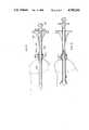
- FIG. 1is a three-dimensional view illustrating one form of self-locking pin constructed in accordance with the present invention, FIG. 1a illustrating a variation:
- FIG. 2is a side elevational view, partly in section, of the device of FIG. 1;
- FIG. 3illustrates the manner of using the device of FIGS. 1 and 2 for internally fixing a bone fracture
- FIG. 4is a view similar to that of FIG. 1, but showing the operations performed for fixing the device in the bone;
- FIG. 5is a fragmentary view illustrating the end of the device when the procedure has been completed
- FIG. 6is a three-dimensional view illustrating another form of self-locking pin device constructed in accordance with the present invention.
- FIGS. 7 and 8illustrate a still further form of self-locking pin device constructed in accordance with the present invention, the device being equipped with manually-gripping means for facilitating the use of the device, FIG. 7 illustrating the components of the manually-gripping means in their locking positions, while FIG. 8 illustrates them in their releasing positions;
- FIGS. 9 and 10illustrate a still further variation of the invention.
- the self-locking pin device illustrated in FIGS. 1-5is particularly useful for internally fixing bone fractures. It comprises three basic components, namely: a pin 2; a tube 3 received over pin 2; and a collar 4 received between one end, namely the proximal end, of pin 2 and tube 3.
- Pin 2may be conventional K-wire commonly used in internally fixing bone fractures. Such wires are made of stainless steel and generally are of diameters ranging from 0.5 to 3.0 mm.
- the distal end of pin 2is formed with: a pointed tip 21, an enlargement 22 inwardly spaced from the pointed tip, a cutting edge 23 between tip 21 and enlargement 22, and a tapered junction 24 between enlargement 22 and the inner part of the pin.
- the enlargement, therein designated 22ais formed by flattening end of pin 2 in order to widen it, and then giving it a twist.
- the opposite sidesare formed with cutting edges 23a and with a pointed tip 21a as in FIG. 1.
- the outer tube 3may also be of stainless steel. It is received over pin 2, but its inner diameter is less than that of the in enlargement 22.
- the distal end of tube 3is formed with two or more axially-extending slits 31; and the proximal end of the tube is similarly formed with two or more axially-extending slits 32.
- Slits 31permit the distal end of the tube to be splayed, i.e. bent outwardly, as shown at 33 in FIGS. 3 and 4; and similarly, slits 32 permit the proximal end of the tube to be splayed as shown at 34.
- Collar 4 received over the proximal end of pin 2 between it and the proximal end of tube 3,may also be made of stainless steel. It has the same inner and outer diameters as tube 3, but is of much shorter length, being in the order of about twice the length of the axial slits 32 formed in the proximal end of the tube.
- the distal end of collar 4is preferably formed with a tapered leading edge, as shown at 41 in FIG. 3, to facilitate the insertion of the collar between pin 2 and tube 3, and its movement axially of the pin in order to splay the proximal end of the tube, as will be described more particularly below.
- the self-locking pin device illustrated in FIGS. 1 and 2may be used in the following manner for internally fixing a fracture in a bone B as illustrated in FIG. 3.
- the deviceWith its components assembled as illustrated in FIGS. 1 and 2, is introduced into the fractured bone B by rotating the device such that the pointed and cutting edge 23, at the distal end of pin 2, serves as a drill bit for penetrating the bone.
- Another alternativeis to introduce the device in predrilled holes through the bone.
- the proximal end of pin 2may be left protruding from bone and skin, for use in connecting the pin to an elastic bandage or to a fixation or treatment device, or for use latter in facilitating the extraction of the pin after the bone has healed.
- the proximal end of pin 2can be severed, and the proximal end of tube 3 crimped over the proximal end of tube 2 and of collar 4, as shown at 36 in FIG. 5.
- FIG. 6illustrates a modification, wherein the distal end of the pin, therein designated 2', is formed with an extension for effecting external fixation or for better axial stabilization in larger bones.
- the enlargement 22'is formed somewhat inwardly of the distal end of pin 2' to provide the extension 26'.
- the distal tip of the pinis here also pointed and formed with a sharpened edge, as shown at 27', to facilitate its introduction into the bone by rotation in the same manner as described above.
- FIGS. 7 and 8illustrate a further embodiment of the invention wherein the device is equipped with manually gripping means to facilitate the insertion of the pin and the splaying of the two ends of the tube when fixing the pin within the fractured bone.
- the device illustrated in FIGS. 7 and 8also includes a pin 102 enclosed within a tube 103 and having a collar 104 between the distal ends of the pin and tube, all having the same structure as described above with respect to pin 2, tube 3, and collar 4, respectively.
- Sleeve 105is formed with an axial bore 151 for receiving the proximal end of pin 102.
- Sleeve 105is further formed with an annular recess 152 extending axially from its distal end for most of the length of the sleeve, to provide an inner sleeve section 105a and an outer sleeve section 105b, the latter terminating in a resilient extension 153 at the distal end of the sleeve.
- the outer sleeve section 105bis externally threaded, as shown at 154, from extension 153 to the proximal end of the sleeve.
- the distal resilient end 153 of the sleeveis formed with an outer tapered face 156, increasing in diameter towards the distal end of the sleeve, and terminating in an annular rib 157 at the distal end of the sleeve.
- Cap 106is formed with an end wall 161 having a central aperture 162 for receiving the proximal end of pin 102.
- Wall 161is of larger diameter than the remainder of the cap to define an enlarged head, as shown at 163.
- Retainer clip 108 received on the proximal end of pin 102retains the cap on the pin, but permits the cap to be rotated with respect to the pin.
- Cap 106further includes internal threads 164 adapted to mate with external threads 154 in sleeve 105.
- cap 106is formed with an annular recess 165 adjacent to its enlarged head 163.
- Locking ring 107has an internal diameter substantially equal to the outer diameter of cap 106 to permit the locking ring to be slid along the outer face of the cap, and then over the tapered face 156 of sleeve 105.
- An enlarged head 171 at the distal end of the locking ringfacilitates sliding it.
- the locking ringis further formed with an outwardly tapered surface 172 engageable with the annular rib 157 in sleeve 105 when the locking ring is in its locking position (FIG. 7), and with an internal annular rib 173 receivable within annular recess 165 in cap 106 when the locking ring is in its released position (FIG. 8).
- the self-locking pin device illustrated in FIGS. 7 and 8may be used in the following manner:
- the devicewould be assembled and supplied to the user in the condition illustrated in FIG. 7, wherein: pin 102 passes through sleeve 105 and cap 106; tube 103 is received within the annular recess 152 formed in sleeve 105; and collar 104 is received between pin 102 and tube 103 and bears, at its proximal end, against the end of the inner sleeve section 105a.
- the locking ring 107is in its locking position overlying extension 153 of the outer sleeve section 105b, limiting against annular rib 157.
- Cap 106in this assembled condition of the device, is threaded to its innermost position bearing against the end of locking ring 107, and thereby firmly locks it in its locking condition.
- the devicemay thus be introduced into the fractured bone by rotation, in the manner described above with respect to FIGS. 1-5, cap 106 providing a convenient manual grip for this purpose.
- locking ring ring 107is manually slid from its locking position against rib 157 on sleeve 105, to its unlocking position against head 163 of cap 106, and is retained in this unlocking position by its rib 173 received within annular recess 165 formed in the cap. This releases the gripping effected between tube 103, collar 104, and pin 102.
- cap 106may be rotated to unthread itself from threads 154 of sleeve 105, which thereby causes pin 102 to move outwardly, and the collar 104 to move inwardly (in the same directions as indicated by arrows A 1 and A 2 , respectively, in FIG. 4) to thereby splay the opposite ends of tube 102 in the same manner as described above with respect to FIG. 4, thereby firmly fixing the device in the fractured bone.
- the protruding portions of the pin 102 and tube 103may be left protruding, with or without the manually-griping members 105-108, or may be severed and the ends crimped, as described above with respect to FIGS. 1-5.
- collar 104is shown as a separate distinct member as in the embodiments illustrated in FIGS. 1-6. However, it will be appreciated that this collar could be integrally formed with the inner section 105a of sleeve 105 since it moves with it.
- cap 106fixedly connected to or integral with pin 102.
- the rotation of the capwould cause the pin also to turn in the same direction, and locking the cap by the locking ring will stabilize the pin as well.
- a still further variationwould be to omit the cap 106, and instead, to provide the proximal part of the pin with means for rotating it by the use of a tool, such as a screwdriver or wrench.
- a toolsuch as a screwdriver or wrench.
- the movement of the collarcould be guided by small protuberances formed on its outer face movable within the slits in the proximal end of the tube.
- FIGS. 9 and 10illustrate a still further variation, including a pin 202 enclosed within a tube 203 split at its distal end, and formed with an annular flange 203a at its proximal end.
- the latter flangeis enclosed by an enlarged portion 204a of a sleeve 204, such that annular wall 204b of sleeve 204 bears against annular flange 203a of tube 203.
- the proximal end of sleeve 204is fixed to a collar 206, and the proximal end of pin 202 is fixed to a cap 207 threadedly received within collar 206.
- cap 207is threaded outwardly from collar 206, to the position illustrated in FIG.
- annular wall 204b of sleeve 204engages annular flange 203a of tube 203, pushing the tube in the inward direction and pulling the pin in the outward direction, as shown in FIG. 10, thereby firmly anchoring the pin between the split ends of tube 203 and annular wall 204c of sleeve 204.
Landscapes
- Health & Medical Sciences (AREA)
- Orthopedic Medicine & Surgery (AREA)
- Surgery (AREA)
- Life Sciences & Earth Sciences (AREA)
- Heart & Thoracic Surgery (AREA)
- Nuclear Medicine, Radiotherapy & Molecular Imaging (AREA)
- Engineering & Computer Science (AREA)
- Biomedical Technology (AREA)
- Neurology (AREA)
- Medical Informatics (AREA)
- Molecular Biology (AREA)
- Animal Behavior & Ethology (AREA)
- General Health & Medical Sciences (AREA)
- Public Health (AREA)
- Veterinary Medicine (AREA)
- Surgical Instruments (AREA)
Abstract
Description
The present invention relates to self-locking pin devices. The invention is particularly useful for internally fixing bone fractures, and is therefore described below with respect to this application, but it will be appreciated that the invention could advantageously be used in other applications as well.
Fractures of the phalanges (i.e., the bones in the fingers and toes) are one of the most common encountered in the human skeleton. Many of these fractures and those of other small bones, and small bone fragments, must be treated by internal fixation methods in order to achieve good anatomical position, early mobilization, and fast and complete rehabilitation of the injured patient. The internal fixation techniques commonly followed today use Kirschner wires (K-wires), intermeduallary pins, wirings, plates, or screws, and combinations of the foregoing, the object being to reach the best anatomical and functional condition of the traumatized bone in the simplest operative procedure and with a minimal use of foreign implanted stabilizing material.
A fixation of the fractured line by a single K-wire is usually the least harmful and the easiest to execute. However, a single K-wire stabilizes only a single spacial plane of movement, whereas the forces acting on the fractured bone are usually in more than one plane; therefore this technique is impractical in most cases. Probably the most common procedure is to use two crossed K-wires transcutaneously or through an explorative incision, but this is a rather extensive procedure and produces a relatively large mass of foreign implanted material. Other internal fixation methods involve even more extensive procedures, with a greater iatrogenic trauma to the injury, and with a larger mass of foreign implanted material, in order to produce a three-place stabilization of the fractured bone.
An object of the present invention is to provide a self-locking pin device particularly useful for internally fixing bone fractures and having advantages in the above respects over the presently used techniques. Another object of the invention is to provide a self-locking pin device which may be used in other applications, wherever a firm fixation is required with respect to multiplanar forces, and access is provided only from one side of the object to be fixed.
According to a broad aspect of the present invention, there is provided a self-locking pin device comprising: a pin having proximal and distal ends and formed with an enlargement in the region of its distal end; a tube received over the pin and having a diameter smaller than said enlargement, the tube being axially split at both its distal and proximal ends; and a collar received between the proximal ends of the pin and tube, such that effecting relative axial movement between the enlargement at the distal end of the pin and the distal end of the tube splays outwardly the distal end of the tube about its axial split, and effecting relative axial movement between the collar and the proximal end of the tube splays outwardly the proximal end of the tube along its axial split.
According to a further feature in one of the preferred embodiments of theinvention described below, the device further includes manually-gripping means attachable to the proximal end of the pin, tube, and collar, to facilitate their insertion and the splaying of the two ends of the tube. More particularly, the manually-gripping means comprises: a sleeve formed with an axial bore for receiving the proximal end of the pin, and with an annular recess extending axially of its distal end for receiving the proximal end of the tube; and a locking ring movable either to a locking position at the distal end of the sleeve, wherein it cams same inwardly to cause it to grip the pin and tube, or to a releasing position away from the distal end of the sleeve causing it to release the pin and tube.
As will be described below, self-locking pin devices constructed in accordance with the foregoing features may be used for internally fixing fractures in an operative procedure which is simple, less traumatic than presently followed procedures, involves a minimal use of foreign implanted material, and stabilizes the fracture line in three spacial planes.
Further features and advantages of the invention will be apparent from the description below.
The invention is herein described, by way of example only, with reference to the accompanying drawings, wherein:
FIG. 1 is a three-dimensional view illustrating one form of self-locking pin constructed in accordance with the present invention, FIG. 1a illustrating a variation:
FIG. 2 is a side elevational view, partly in section, of the device of FIG. 1;
FIG. 3 illustrates the manner of using the device of FIGS. 1 and 2 for internally fixing a bone fracture;
FIG. 4 is a view similar to that of FIG. 1, but showing the operations performed for fixing the device in the bone;
FIG. 5 is a fragmentary view illustrating the end of the device when the procedure has been completed;
FIG. 6 is a three-dimensional view illustrating another form of self-locking pin device constructed in accordance with the present invention;
FIGS. 7 and 8 illustrate a still further form of self-locking pin device constructed in accordance with the present invention, the device being equipped with manually-gripping means for facilitating the use of the device, FIG. 7 illustrating the components of the manually-gripping means in their locking positions, while FIG. 8 illustrates them in their releasing positions;
and FIGS. 9 and 10 illustrate a still further variation of the invention.
The self-locking pin device illustrated in FIGS. 1-5 is particularly useful for internally fixing bone fractures. It comprises three basic components, namely: apin 2; atube 3 received overpin 2; and a collar 4 received between one end, namely the proximal end, ofpin 2 andtube 3.
According to the variation illustrated in FIG. 1a, the enlargement, therein designated 22a, is formed by flattening end ofpin 2 in order to widen it, and then giving it a twist. The opposite sides are formed withcutting edges 23a and with apointed tip 21a as in FIG. 1.
Theouter tube 3 may also be of stainless steel. It is received overpin 2, but its inner diameter is less than that of the inenlargement 22. The distal end oftube 3 is formed with two or more axially-extendingslits 31; and the proximal end of the tube is similarly formed with two or more axially-extendingslits 32.Slits 31 permit the distal end of the tube to be splayed, i.e. bent outwardly, as shown at 33 in FIGS. 3 and 4; and similarly,slits 32 permit the proximal end of the tube to be splayed as shown at 34.
Collar 4 received over the proximal end ofpin 2 between it and the proximal end oftube 3, may also be made of stainless steel. It has the same inner and outer diameters astube 3, but is of much shorter length, being in the order of about twice the length of theaxial slits 32 formed in the proximal end of the tube. The distal end of collar 4 is preferably formed with a tapered leading edge, as shown at 41 in FIG. 3, to facilitate the insertion of the collar betweenpin 2 andtube 3, and its movement axially of the pin in order to splay the proximal end of the tube, as will be described more particularly below.
The self-locking pin device illustrated in FIGS. 1 and 2 may be used in the following manner for internally fixing a fracture in a bone B as illustrated in FIG. 3.
Thus, the device, with its components assembled as illustrated in FIGS. 1 and 2, is introduced into the fractured bone B by rotating the device such that the pointed andcutting edge 23, at the distal end ofpin 2, serves as a drill bit for penetrating the bone. Another alternative is to introduce the device in predrilled holes through the bone. After the device has been inserted into bone B to the position illustrated in FIG. 3,pin 2 is displaced in the outer direction as shown by arrow A1 in FIG. 4, while collar 4 is displaced in the inner direction as shown by arrow A2. Displacingpin 2 in the direction of arrow A1 causes theenlargement 22 at the distal end of the pin to splay or bend outwardly the distal end oftube 3 along itsaxial split 31, a shown at 33 in FIGS. 3 and 4; and displacing collar 4 in the direction of arrow A2, causes the proximal end oftube 3 to be bent outwardly of splayed as shown at 34 in FIGS. 3 and 4.Pin 2 is thus firmly fixed at both its ends within the fractured bone, thereby firmly stabilizing the fracture line in the three spacial planes.
The proximal end ofpin 2 may be left protruding from bone and skin, for use in connecting the pin to an elastic bandage or to a fixation or treatment device, or for use latter in facilitating the extraction of the pin after the bone has healed. Alternatively, the proximal end ofpin 2 can be severed, and the proximal end oftube 3 crimped over the proximal end oftube 2 and of collar 4, as shown at 36 in FIG. 5.
When removing the pin device, the reverse procedure is followed; that is, the crimpedend 36 oftube 3 is opened; collar 4 is pulled in the outer direction (opposite to direction A2 of FIG. 4); andpin 2 is pushed in the inner direction (i.e. opposite to direction A1 in FIG. 4), whereupon the device is released from the bone and may be pulled outwardly therefrom.
FIG. 6 illustrates a modification, wherein the distal end of the pin, therein designated 2', is formed with an extension for effecting external fixation or for better axial stabilization in larger bones. Thus, in this modification, the enlargement 22' is formed somewhat inwardly of the distal end of pin 2' to provide the extension 26'. The distal tip of the pin is here also pointed and formed with a sharpened edge, as shown at 27', to facilitate its introduction into the bone by rotation in the same manner as described above.
FIGS. 7 and 8 illustrate a further embodiment of the invention wherein the device is equipped with manually gripping means to facilitate the insertion of the pin and the splaying of the two ends of the tube when fixing the pin within the fractured bone. Thus, the device illustrated in FIGS. 7 and 8 also includes apin 102 enclosed within atube 103 and having acollar 104 between the distal ends of the pin and tube, all having the same structure as described above with respect topin 2,tube 3, and collar 4, respectively. The device of FIGS. 7 and 8, however, includes additional components serving as the manually-gripping means, namely: asleeve 105, acap 106, alocking ring 107, and aretainer clip 108.
Lockingring 107 has an internal diameter substantially equal to the outer diameter ofcap 106 to permit the locking ring to be slid along the outer face of the cap, and then over the taperedface 156 ofsleeve 105. Anenlarged head 171 at the distal end of the locking ring facilitates sliding it. The locking ring is further formed with an outwardlytapered surface 172 engageable with theannular rib 157 insleeve 105 when the locking ring is in its locking position (FIG. 7), and with an internalannular rib 173 receivable withinannular recess 165 incap 106 when the locking ring is in its released position (FIG. 8).
The self-locking pin device illustrated in FIGS. 7 and 8 may be used in the following manner:
Normally, the device would be assembled and supplied to the user in the condition illustrated in FIG. 7, wherein: pin 102 passes throughsleeve 105 andcap 106;tube 103 is received within theannular recess 152 formed insleeve 105; andcollar 104 is received betweenpin 102 andtube 103 and bears, at its proximal end, against the end of theinner sleeve section 105a. In addition, in this assembled condition of the device, thelocking ring 107 is in its locking positionoverlying extension 153 of theouter sleeve section 105b, limiting againstannular rib 157. Because of the taperedsurface 156 of theouter sleeve section 105b, the latter is cammed inwardly by the lockingring 107 to tightly griptube 103 andcollar 104 between it andpin 102.Cap 106, in this assembled condition of the device, is threaded to its innermost position bearing against the end of lockingring 107, and thereby firmly locks it in its locking condition.
The device may thus be introduced into the fractured bone by rotation, in the manner described above with respect to FIGS. 1-5,cap 106 providing a convenient manual grip for this purpose. As soon as the device has been introduced completely into the fractured bone, lockingring ring 107 is manually slid from its locking position againstrib 157 onsleeve 105, to its unlocking position againsthead 163 ofcap 106, and is retained in this unlocking position by itsrib 173 received withinannular recess 165 formed in the cap. This releases the gripping effected betweentube 103,collar 104, andpin 102.
At this time,cap 106 may be rotated to unthread itself fromthreads 154 ofsleeve 105, which thereby causespin 102 to move outwardly, and thecollar 104 to move inwardly (in the same directions as indicated by arrows A1 and A2, respectively, in FIG. 4) to thereby splay the opposite ends oftube 102 in the same manner as described above with respect to FIG. 4, thereby firmly fixing the device in the fractured bone.
After the device has been thus fixed in the fractured bone, the protruding portions of thepin 102 andtube 103 may be left protruding, with or without the manually-griping members 105-108, or may be severed and the ends crimped, as described above with respect to FIGS. 1-5.
The procedure for extracting the pin is substantially reversed to that described above for introducing it. Thus, when extracting the pin, thecap 106 is threaded inwardly oversleeve 154, and the protrudingpin 102 is then pushed slightly inwardly by hand so as to release the inner end of the splayed end oftube 103. Lockingcollar 107 is then moved over theresilient extension 153 ofsleeve 105 to lock the parts; and then pin 102 is withdrawn from the bone, this being facilitated by grippingcap 106.
In the modification illustrated in FIGS. 7 and 8,collar 104 is shown as a separate distinct member as in the embodiments illustrated in FIGS. 1-6. However, it will be appreciated that this collar could be integrally formed with theinner section 105a ofsleeve 105 since it moves with it.
Another modification would be to havecap 106 fixedly connected to or integral withpin 102. In this case, the rotation of the cap would cause the pin also to turn in the same direction, and locking the cap by the locking ring will stabilize the pin as well.
A still further variation would be to omit thecap 106, and instead, to provide the proximal part of the pin with means for rotating it by the use of a tool, such as a screwdriver or wrench. In this variation, the movement of the collar could be guided by small protuberances formed on its outer face movable within the slits in the proximal end of the tube.
FIGS. 9 and 10 illustrate a still further variation, including apin 202 enclosed within atube 203 split at its distal end, and formed with anannular flange 203a at its proximal end. The latter flange is enclosed by anenlarged portion 204a of asleeve 204, such thatannular wall 204b ofsleeve 204 bears againstannular flange 203a oftube 203. The proximal end ofsleeve 204 is fixed to acollar 206, and the proximal end ofpin 202 is fixed to acap 207 threadedly received withincollar 206. Thus, whencap 207 is threaded outwardly fromcollar 206, to the position illustrated in FIG. 10,annular wall 204b ofsleeve 204 engagesannular flange 203a oftube 203, pushing the tube in the inward direction and pulling the pin in the outward direction, as shown in FIG. 10, thereby firmly anchoring the pin between the split ends oftube 203 andannular wall 204c ofsleeve 204.
While the invention has been described with respect to several embodiments, particularly applicable to internally fixing bone fractures, it will be appreciated that the described devices could be used in many other applications, for firmly anchoring a self-locking pin to a body, where there is access only from one side of the body, for example, for mounting a self-locking pin through a wooden, metal, or concrete panel wherein the pin is to be fixed to the opposite sides of the panel but access is provided from only one side of the panel.
Many other variations, modifications, and applications of the invention will be apparent.
Claims (22)
1. A self-locking pin device comprising:
a pin having proximal and distal ends and formed with an enlargement in the region of its distal end;
a tube received over said pin and having a diameter smaller than said enlargement, said tube being axially split at both its distal and proximal ends;
a collar received between the proximal ends of said pin and tube, such that affecting relative axial movement between the enlargement at the distal end of the pin and the distal end of the tube splays outwardly the distal end of the tube about its axial split, and effecting relative axial movement between the collar and the proximal end of the tube splays outwardly the proximal end of the tube along its axial split;
and manually gripping means attachable to the proximal end of the pin, tube and collar, to facilitate their insertion and the splaying of the two ends of the tube.
2. The device according to claim 1, wherein said distal end of a pin is formed with a cutting edge to facilitate inserting the pin by rotation.
3. The device according to claim 1,
wherein the distal edge of the collar is tapered.
4. The device according to claim 1,
wherein said enlargement is formed at the distal end of the pin.
5. The device according to claim 1,
wherein said pin is of a diameter of 0.5 to 1.5 mm.
6. The device according to claim 1,
wherein said pin is of stainles steel.
7. The device according to claim 6, wherein said tube and collar are also of stainless steel.
8. The device according to claim 1, wherein said manually gripping means comprises:
a sleeve formed with an axial bore for receiving the proximal end of the pin, and with an annular recess extending axially of its distal end for receiving the proximal end of the tube;
and a locking ring movable either to a locking position at the distal end of said sleeeve, wherein it cams same inwardly to cause it to grip said pin and tube, or to a releasing position away from said distal end of the sleeve causing same to release said pin and tube.
9. The device according to claim 8, wherein the distal end of said sleeve is formed with a tapered outer face increasing in diameter towards its distal end, which tapered outer face receives said locking ring when moved to its locking position.
10. The device according to claim 9, wherein said tapered outer face of the sleeve terminates in an annular rib at its distal end, which rib serves as a limit for the locking ring when moved to its locking position.
11. The device according to claim 8,
wherein said manually gripping means further comprises: a cap received over the proximal end of the sleeve and retaining said locking means in its locking position over the distal end of said sleeve.
12. The device according to claim 11, wherein the proximal end of said sleeve is formed with external thread mating with internal threads formed in said cap.
13. The device according to claim 12, wherein said cap is formed with a central bore receiving the proximal end of said pin.
14. The device according to claim 13, wherein the proximal end of said pin passes through said central bore of the cap, the device further including: a retainer clip for retaining the cap on the proximal end of the pin while permitting the cap to be rotated with respect to the pin.
15. The device according to claim 13,
wherein said cap is formed at its proximal end with an enlarged head serving as a limit for the locking ring when moved to its releasing position.
16. The device according to claim 15, wherein said cap is further formed at its proximal end with an annular recess for receiving an annular rib formed on the inner face of said locking ring for retaining same in its releasing position.
17. The device according to claim 8,
wherein said collar is formed as a separate member from, and engageable with, said sleeve.
18. The device according to claim 8,
wherein said collar is integrally formed with said sleeve.
19. The device according to claim 8,
wherein said cap is formed as a separate member from said pin.
20. The device according to claim 8,
wherein said cap is fixedly connected to the proximal end of said pin.
21. The device according to claim 8,
wherein the proximal end of said pin is formed with means for rotating same, and said collar includes protuberances formed on its outer face movable within the slits in the proximal end of said tube.
22. A self-locking pin device comprising:
a pin having proximal and distal ends and formed with an enlargement in the region of its distal end;
a tube received over said pin and having a diameter smaller than said enlargement, said tube being axially split at both its distal and proximal ends;
and a collar received between the proximal ends of said pin and tube, such that effecting relative axial movement between the enlargement at the distal end of the pin and the distal end of the tube splays outwardly the distal end of the tube about its axial split, and effecting relative axial movement between the collar and the proximal end of the tube splays outwardly the proximal end of the tube along its axial split;
said enlargement being formed inwardly of the distal end of the pin to provide an extension for effecting external fixation to the pin.
Applications Claiming Priority (2)
| Application Number | Priority Date | Filing Date | Title |
|---|---|---|---|
| IL70736 | 1984-01-20 | ||
| IL70736AIL70736A (en) | 1984-01-20 | 1984-01-20 | Self-locking pin device particularly useful for internally fixing bone fractures |
Publications (1)
| Publication Number | Publication Date |
|---|---|
| US4790304Atrue US4790304A (en) | 1988-12-13 |
Family
ID=11054792
Family Applications (1)
| Application Number | Title | Priority Date | Filing Date |
|---|---|---|---|
| US06/690,323Expired - Fee RelatedUS4790304A (en) | 1984-01-20 | 1985-01-10 | Self-locking pin device particularly useful for internally fixing bone fractures |
Country Status (2)
| Country | Link |
|---|---|
| US (1) | US4790304A (en) |
| IL (1) | IL70736A (en) |
Cited By (106)
| Publication number | Priority date | Publication date | Assignee | Title |
|---|---|---|---|---|
| US4928679A (en)* | 1987-07-21 | 1990-05-29 | Landos Applications Orthopediques Francaises | Centro-medullary nailing rod |
| US5167665A (en)* | 1991-12-31 | 1992-12-01 | Mckinney William W | Method of attaching objects to bone |
| US5196016A (en)* | 1991-03-11 | 1993-03-23 | Institut Straumann Ag | Auxiliary means and method for fastening a capping on bone tissue or the like |
| US5354298A (en)* | 1991-03-22 | 1994-10-11 | United States Surgical Corporation | Suture anchor installation system |
| US5441500A (en)* | 1991-01-30 | 1995-08-15 | Howmedica Gmbh | Bone nail |
| US5480403A (en)* | 1991-03-22 | 1996-01-02 | United States Surgical Corporation | Suture anchoring device and method |
| FR2735010A1 (en)* | 1995-06-07 | 1996-12-13 | Worcel Alexandre | RING OF OSTEOSYNTHESIS USABLE IN COMBINATION WITH A SPINDLE OR A SCREW, AND ANCILLARY FOR ITS COMPRESSION. |
| US5628751A (en)* | 1993-06-21 | 1997-05-13 | United States Surgical Corporation | Orthopedic fastener applicator with rotational or longitudinal driver |
| US5713903A (en)* | 1991-03-22 | 1998-02-03 | United States Surgical Corporation | Orthopedic fastener |
| US5720753A (en)* | 1991-03-22 | 1998-02-24 | United States Surgical Corporation | Orthopedic fastener |
| US5725541A (en)* | 1996-01-22 | 1998-03-10 | The Anspach Effort, Inc. | Soft tissue fastener device |
| US5741282A (en)* | 1996-01-22 | 1998-04-21 | The Anspach Effort, Inc. | Soft tissue fastener device |
| WO1998010693A3 (en)* | 1996-09-10 | 1998-07-02 | Li Medical Tech Inc | Surgical anchor and package and cartridge for surgical anchor |
| US5893850A (en)* | 1996-11-12 | 1999-04-13 | Cachia; Victor V. | Bone fixation device |
| US5928244A (en)* | 1996-10-04 | 1999-07-27 | United States Surgical Corporation | Tissue fastener implantation apparatus and method |
| US5948000A (en)* | 1996-10-03 | 1999-09-07 | United States Surgical Corporation | System for suture anchor placement |
| US5948001A (en)* | 1996-10-03 | 1999-09-07 | United States Surgical Corporation | System for suture anchor placement |
| US5993459A (en)* | 1996-10-04 | 1999-11-30 | Larsen; Scott | Suture anchor installation system with insertion tool |
| US6019762A (en)* | 1998-04-30 | 2000-02-01 | Orthodyne, Inc. | Adjustable length orthopedic fixation device |
| WO2000006037A1 (en)* | 1998-07-25 | 2000-02-10 | Helke Lob | Fixing element for bone fragments |
| US6159210A (en)* | 1997-01-14 | 2000-12-12 | Research Corporation Technologies, Inc. | Bone fixation pin with rotary cutting tip |
| US6187008B1 (en) | 1999-07-07 | 2001-02-13 | Bristol-Myers Squibb | Device for temporarily fixing bones |
| US6190401B1 (en)* | 1991-05-13 | 2001-02-20 | United States Surgical Corporation | Device for applying a meniscal staple |
| WO2001034045A1 (en)* | 1999-11-11 | 2001-05-17 | Synthes Ag Chur | Radially expandable intramedullary nail |
| US6273892B1 (en)* | 1998-09-10 | 2001-08-14 | Hand Innovations, Inc. | Fracture fixation system |
| WO2001080751A1 (en) | 2000-04-26 | 2001-11-01 | Anchor Medical Technologies, Inc. | Bone fixation system |
| US6511481B2 (en) | 2001-03-30 | 2003-01-28 | Triage Medical, Inc. | Method and apparatus for fixation of proximal femoral fractures |
| US6533788B1 (en) | 2001-11-01 | 2003-03-18 | Hand Innovations, Inc. | Locking device for intramedullary pin fixation |
| US20030149436A1 (en)* | 2002-02-04 | 2003-08-07 | Mcdowell Charles L. | Fixation and compression fastener assembly for bone fractures |
| US6632224B2 (en) | 1996-11-12 | 2003-10-14 | Triage Medical, Inc. | Bone fixation system |
| US6648890B2 (en) | 1996-11-12 | 2003-11-18 | Triage Medical, Inc. | Bone fixation system with radially extendable anchor |
| US20040002709A1 (en)* | 2002-06-28 | 2004-01-01 | Stefan Gabriel | Soft tissue repair tool |
| US6685706B2 (en) | 2001-11-19 | 2004-02-03 | Triage Medical, Inc. | Proximal anchors for bone fixation system |
| WO2004078220A2 (en) | 2003-02-28 | 2004-09-16 | Triage Medical Inc. | Tool for bone fixation device |
| US6887243B2 (en) | 2001-03-30 | 2005-05-03 | Triage Medical, Inc. | Method and apparatus for bone fixation with secondary compression |
| US20050143734A1 (en)* | 1996-11-12 | 2005-06-30 | Cachia Victor V. | Bone fixation system with radially extendable anchor |
| US6951561B2 (en) | 2003-05-06 | 2005-10-04 | Triage Medical, Inc. | Spinal stabilization device |
| US7037324B2 (en) | 2000-09-15 | 2006-05-02 | United States Surgical Corporation | Knotless tissue anchor |
| US7070601B2 (en) | 2003-01-16 | 2006-07-04 | Triage Medical, Inc. | Locking plate for bone anchors |
| US20080086131A1 (en)* | 2006-10-06 | 2008-04-10 | Depuy Spine, Inc. | Bone screw fixation |
| US20080125818A1 (en)* | 2006-09-22 | 2008-05-29 | Sidebotham Christopher G | Interlocking nail geometry and method of use |
| US20100036440A1 (en)* | 2008-08-11 | 2010-02-11 | Arch Day Design, Llc | Collapsible bone screw apparatus |
| WO2010042293A1 (en)* | 2008-10-07 | 2010-04-15 | Synthes Usa, Llc | Expandable bone support |
| US7815659B2 (en) | 2005-11-15 | 2010-10-19 | Ethicon Endo-Surgery, Inc. | Suture anchor applicator |
| US7824429B2 (en) | 2002-07-19 | 2010-11-02 | Interventional Spine, Inc. | Method and apparatus for spinal fixation |
| US20100331881A1 (en)* | 2009-06-24 | 2010-12-30 | Rickey Hart | Method And Apparatus For Soft Tissue Fixation To Bone |
| US7867264B2 (en)* | 2000-11-16 | 2011-01-11 | Ethicon, Inc. | Apparatus and method for attaching soft tissue to bone |
| US7896907B2 (en) | 1999-07-23 | 2011-03-01 | Ethicon, Inc. | System and method for attaching soft tissue to bone |
| US20110144766A1 (en)* | 2008-06-19 | 2011-06-16 | Shreedhar Kale | Allograft Bone Plugs, Systems and Techniques |
| US7998176B2 (en) | 2007-06-08 | 2011-08-16 | Interventional Spine, Inc. | Method and apparatus for spinal stabilization |
| US20120071878A1 (en)* | 2010-09-22 | 2012-03-22 | David Cowin | Fracture management tool and method |
| WO2012129183A1 (en) | 2011-03-21 | 2012-09-27 | Ronald Childs | Sleeve for bone fixation device |
| US8282675B2 (en) | 2008-01-25 | 2012-10-09 | Depuy Spine, Inc. | Anti-backout mechanism |
| US8535322B1 (en)* | 2012-11-07 | 2013-09-17 | Roy Y. Powlan | Hip nail and inertial insertion tooling |
| US20140257420A1 (en)* | 2011-10-10 | 2014-09-11 | William Casey Fox | Shape changing bone implant and method of use for enhancing healing |
| US9089379B2 (en) | 2012-07-18 | 2015-07-28 | Jmea Corporation | Multi-impact system for prosthesis deployment device |
| US9474561B2 (en) | 2013-11-19 | 2016-10-25 | Wright Medical Technology, Inc. | Two-wire technique for installing hammertoe implant |
| US9498266B2 (en) | 2014-02-12 | 2016-11-22 | Wright Medical Technology, Inc. | Intramedullary implant, system, and method for inserting an implant into a bone |
| US9498273B2 (en) | 2010-06-02 | 2016-11-22 | Wright Medical Technology, Inc. | Orthopedic implant kit |
| US9504582B2 (en) | 2012-12-31 | 2016-11-29 | Wright Medical Technology, Inc. | Ball and socket implants for correction of hammer toes and claw toes |
| US9510816B2 (en) | 1999-08-10 | 2016-12-06 | Depuy Mitek, Llc | Self-locking suture anchor |
| US9522070B2 (en) | 2013-03-07 | 2016-12-20 | Interventional Spine, Inc. | Intervertebral implant |
| US9522028B2 (en) | 2013-07-03 | 2016-12-20 | Interventional Spine, Inc. | Method and apparatus for sacroiliac joint fixation |
| US9545274B2 (en)* | 2014-02-12 | 2017-01-17 | Wright Medical Technology, Inc. | Intramedullary implant, system, and method for inserting an implant into a bone |
| US9603643B2 (en) | 2010-06-02 | 2017-03-28 | Wright Medical Technology, Inc. | Hammer toe implant with expansion portion for retrograde approach |
| US20170143395A1 (en)* | 2014-06-13 | 2017-05-25 | Kyungpook National University Industry-Academic Cooperation Foundation | Fixing pin for orthopedic surgery enabling internal fixation |
| US20170189010A1 (en)* | 2011-10-04 | 2017-07-06 | Conmed Corporation | Dual expansion anchor |
| US9724139B2 (en) | 2013-10-01 | 2017-08-08 | Wright Medical Technology, Inc. | Hammer toe implant and method |
| US9724140B2 (en) | 2010-06-02 | 2017-08-08 | Wright Medical Technology, Inc. | Tapered, cylindrical cruciform hammer toe implant and method |
| US9750492B2 (en) | 2006-08-04 | 2017-09-05 | Depuy Mitek, Llc | Suture anchor system with tension relief mechanism |
| US9788825B2 (en) | 2006-08-04 | 2017-10-17 | Depuy Mitek, Llc | Suture anchor with relief mechanism |
| US9808296B2 (en) | 2014-09-18 | 2017-11-07 | Wright Medical Technology, Inc. | Hammertoe implant and instrument |
| US9839530B2 (en) | 2007-06-26 | 2017-12-12 | DePuy Synthes Products, Inc. | Highly lordosed fusion cage |
| US9883951B2 (en) | 2012-08-30 | 2018-02-06 | Interventional Spine, Inc. | Artificial disc |
| US9895236B2 (en) | 2010-06-24 | 2018-02-20 | DePuy Synthes Products, Inc. | Enhanced cage insertion assembly |
| US9913727B2 (en) | 2015-07-02 | 2018-03-13 | Medos International Sarl | Expandable implant |
| US9931223B2 (en) | 2008-04-05 | 2018-04-03 | DePuy Synthes Products, Inc. | Expandable intervertebral implant |
| US9993349B2 (en) | 2002-06-27 | 2018-06-12 | DePuy Synthes Products, Inc. | Intervertebral disc |
| US10058433B2 (en) | 2012-07-26 | 2018-08-28 | DePuy Synthes Products, Inc. | Expandable implant |
| US10080597B2 (en) | 2014-12-19 | 2018-09-25 | Wright Medical Technology, Inc. | Intramedullary anchor for interphalangeal arthrodesis |
| US10390963B2 (en) | 2006-12-07 | 2019-08-27 | DePuy Synthes Products, Inc. | Intervertebral implant |
| US10398563B2 (en) | 2017-05-08 | 2019-09-03 | Medos International Sarl | Expandable cage |
| US10433977B2 (en) | 2008-01-17 | 2019-10-08 | DePuy Synthes Products, Inc. | Expandable intervertebral implant and associated method of manufacturing the same |
| US10441317B2 (en) | 2016-10-26 | 2019-10-15 | SIGN Fracture Care International | Bone fixation system and method using a clamping instrument to guide fastener placement |
| US10500062B2 (en) | 2009-12-10 | 2019-12-10 | DePuy Synthes Products, Inc. | Bellows-like expandable interbody fusion cage |
| US10537436B2 (en) | 2016-11-01 | 2020-01-21 | DePuy Synthes Products, Inc. | Curved expandable cage |
| US10548741B2 (en) | 2010-06-29 | 2020-02-04 | DePuy Synthes Products, Inc. | Distractible intervertebral implant |
| US10888433B2 (en) | 2016-12-14 | 2021-01-12 | DePuy Synthes Products, Inc. | Intervertebral implant inserter and related methods |
| US10940016B2 (en) | 2017-07-05 | 2021-03-09 | Medos International Sarl | Expandable intervertebral fusion cage |
| US11020218B2 (en) | 2013-03-14 | 2021-06-01 | Conmed Corporation | Tissue capturing bone anchor |
| US11344424B2 (en) | 2017-06-14 | 2022-05-31 | Medos International Sarl | Expandable intervertebral implant and related methods |
| US11426290B2 (en) | 2015-03-06 | 2022-08-30 | DePuy Synthes Products, Inc. | Expandable intervertebral implant, system, kit and method |
| US11426286B2 (en) | 2020-03-06 | 2022-08-30 | Eit Emerging Implant Technologies Gmbh | Expandable intervertebral implant |
| US11446156B2 (en) | 2018-10-25 | 2022-09-20 | Medos International Sarl | Expandable intervertebral implant, inserter instrument, and related methods |
| US11452607B2 (en) | 2010-10-11 | 2022-09-27 | DePuy Synthes Products, Inc. | Expandable interspinous process spacer implant |
| US11510788B2 (en) | 2016-06-28 | 2022-11-29 | Eit Emerging Implant Technologies Gmbh | Expandable, angularly adjustable intervertebral cages |
| US11596523B2 (en) | 2016-06-28 | 2023-03-07 | Eit Emerging Implant Technologies Gmbh | Expandable and angularly adjustable articulating intervertebral cages |
| US11612491B2 (en) | 2009-03-30 | 2023-03-28 | DePuy Synthes Products, Inc. | Zero profile spinal fusion cage |
| US11752009B2 (en) | 2021-04-06 | 2023-09-12 | Medos International Sarl | Expandable intervertebral fusion cage |
| US11850160B2 (en) | 2021-03-26 | 2023-12-26 | Medos International Sarl | Expandable lordotic intervertebral fusion cage |
| US11911287B2 (en) | 2010-06-24 | 2024-02-27 | DePuy Synthes Products, Inc. | Lateral spondylolisthesis reduction cage |
| USRE49973E1 (en) | 2013-02-28 | 2024-05-21 | DePuy Synthes Products, Inc. | Expandable intervertebral implant, system, kit and method |
| US12090064B2 (en) | 2022-03-01 | 2024-09-17 | Medos International Sarl | Stabilization members for expandable intervertebral implants, and related systems and methods |
| CN118648960A (en)* | 2024-06-26 | 2024-09-17 | 南通大学附属医院 | A phalanx fracture internal fixation tool |
| US12390258B2 (en) | 2012-07-18 | 2025-08-19 | Jmea Corporation | Methods and apparatus for implanting prostheses |
| US12440346B2 (en) | 2023-03-31 | 2025-10-14 | DePuy Synthes Products, Inc. | Expandable intervertebral implant |
Citations (12)
| Publication number | Priority date | Publication date | Assignee | Title |
|---|---|---|---|---|
| US1060543A (en)* | 1912-10-30 | 1913-04-29 | Charles E Evans | Dowel. |
| DE471336C (en)* | 1929-02-12 | Elek Zitaets U Ingenieurbuero | Method for driving apart a slotted dowel sleeve mounted between two drifting bodies for fastening wall dowels | |
| US3208450A (en)* | 1962-03-14 | 1965-09-28 | Abelson Louis | Fracture setting tool |
| US3312139A (en)* | 1964-12-03 | 1967-04-04 | Cristina George R Di | Anchor bolt device securing joined members |
| US3438686A (en)* | 1967-01-23 | 1969-04-15 | Murray Co Inc | Bearing support bushing |
| US4227518A (en)* | 1978-02-12 | 1980-10-14 | Jacob Aginsky | Intramedullary retraction nail for fixation of comminuted fractured bones |
| US4262665A (en)* | 1979-06-27 | 1981-04-21 | Roalstad W L | Intramedullary compression device |
| US4481702A (en)* | 1982-09-30 | 1984-11-13 | The Boeing Company | Method of assembling threaded insert bushing within a working material |
| US4483335A (en)* | 1982-06-02 | 1984-11-20 | Tornier S.A. | Nails for femoral fractures |
| US4522202A (en)* | 1981-01-12 | 1985-06-11 | Schwarzkopf Development Corporation | Curved intramedullary lower leg spike |
| US4562598A (en)* | 1981-04-01 | 1986-01-07 | Mecron Medizinische Produkte Gmbh | Joint prosthesis |
| US4681477A (en)* | 1983-03-19 | 1987-07-21 | Walter Fischer | Invisible connection for faced parts, in particular for furniture |
- 1984
- 1984-01-20ILIL70736Apatent/IL70736A/ennot_activeIP Right Cessation
- 1985
- 1985-01-10USUS06/690,323patent/US4790304A/ennot_activeExpired - Fee Related
Patent Citations (12)
| Publication number | Priority date | Publication date | Assignee | Title |
|---|---|---|---|---|
| DE471336C (en)* | 1929-02-12 | Elek Zitaets U Ingenieurbuero | Method for driving apart a slotted dowel sleeve mounted between two drifting bodies for fastening wall dowels | |
| US1060543A (en)* | 1912-10-30 | 1913-04-29 | Charles E Evans | Dowel. |
| US3208450A (en)* | 1962-03-14 | 1965-09-28 | Abelson Louis | Fracture setting tool |
| US3312139A (en)* | 1964-12-03 | 1967-04-04 | Cristina George R Di | Anchor bolt device securing joined members |
| US3438686A (en)* | 1967-01-23 | 1969-04-15 | Murray Co Inc | Bearing support bushing |
| US4227518A (en)* | 1978-02-12 | 1980-10-14 | Jacob Aginsky | Intramedullary retraction nail for fixation of comminuted fractured bones |
| US4262665A (en)* | 1979-06-27 | 1981-04-21 | Roalstad W L | Intramedullary compression device |
| US4522202A (en)* | 1981-01-12 | 1985-06-11 | Schwarzkopf Development Corporation | Curved intramedullary lower leg spike |
| US4562598A (en)* | 1981-04-01 | 1986-01-07 | Mecron Medizinische Produkte Gmbh | Joint prosthesis |
| US4483335A (en)* | 1982-06-02 | 1984-11-20 | Tornier S.A. | Nails for femoral fractures |
| US4481702A (en)* | 1982-09-30 | 1984-11-13 | The Boeing Company | Method of assembling threaded insert bushing within a working material |
| US4681477A (en)* | 1983-03-19 | 1987-07-21 | Walter Fischer | Invisible connection for faced parts, in particular for furniture |
Cited By (216)
| Publication number | Priority date | Publication date | Assignee | Title |
|---|---|---|---|---|
| US4928679A (en)* | 1987-07-21 | 1990-05-29 | Landos Applications Orthopediques Francaises | Centro-medullary nailing rod |
| US5441500A (en)* | 1991-01-30 | 1995-08-15 | Howmedica Gmbh | Bone nail |
| US5196016A (en)* | 1991-03-11 | 1993-03-23 | Institut Straumann Ag | Auxiliary means and method for fastening a capping on bone tissue or the like |
| US5713903A (en)* | 1991-03-22 | 1998-02-03 | United States Surgical Corporation | Orthopedic fastener |
| US5354298A (en)* | 1991-03-22 | 1994-10-11 | United States Surgical Corporation | Suture anchor installation system |
| US5480403A (en)* | 1991-03-22 | 1996-01-02 | United States Surgical Corporation | Suture anchoring device and method |
| US5720753A (en)* | 1991-03-22 | 1998-02-24 | United States Surgical Corporation | Orthopedic fastener |
| US6190401B1 (en)* | 1991-05-13 | 2001-02-20 | United States Surgical Corporation | Device for applying a meniscal staple |
| US5167665A (en)* | 1991-12-31 | 1992-12-01 | Mckinney William W | Method of attaching objects to bone |
| US5628751A (en)* | 1993-06-21 | 1997-05-13 | United States Surgical Corporation | Orthopedic fastener applicator with rotational or longitudinal driver |
| US5643274A (en)* | 1993-06-21 | 1997-07-01 | United States Surgical Corporation | Orthopedic fastener applicator kit |
| US5993450A (en)* | 1995-06-07 | 1999-11-30 | Worcel; Alexandre | Osteosynthesis ring usable in combination with a pin or a screw, and compressing device therefore |
| WO1996039971A1 (en)* | 1995-06-07 | 1996-12-19 | Alexandre Worcel | Osteosynthesis ring usable in combination with a pin or a screw, and compressing device therefor |
| FR2735010A1 (en)* | 1995-06-07 | 1996-12-13 | Worcel Alexandre | RING OF OSTEOSYNTHESIS USABLE IN COMBINATION WITH A SPINDLE OR A SCREW, AND ANCILLARY FOR ITS COMPRESSION. |
| US5725541A (en)* | 1996-01-22 | 1998-03-10 | The Anspach Effort, Inc. | Soft tissue fastener device |
| US5741282A (en)* | 1996-01-22 | 1998-04-21 | The Anspach Effort, Inc. | Soft tissue fastener device |
| WO1998010693A3 (en)* | 1996-09-10 | 1998-07-02 | Li Medical Tech Inc | Surgical anchor and package and cartridge for surgical anchor |
| US5948001A (en)* | 1996-10-03 | 1999-09-07 | United States Surgical Corporation | System for suture anchor placement |
| US5948000A (en)* | 1996-10-03 | 1999-09-07 | United States Surgical Corporation | System for suture anchor placement |
| US5993459A (en)* | 1996-10-04 | 1999-11-30 | Larsen; Scott | Suture anchor installation system with insertion tool |
| US5928244A (en)* | 1996-10-04 | 1999-07-27 | United States Surgical Corporation | Tissue fastener implantation apparatus and method |
| US20040010257A1 (en)* | 1996-11-12 | 2004-01-15 | Cachia Victor V. | Bone fixation system |
| US6648890B2 (en) | 1996-11-12 | 2003-11-18 | Triage Medical, Inc. | Bone fixation system with radially extendable anchor |
| US6632224B2 (en) | 1996-11-12 | 2003-10-14 | Triage Medical, Inc. | Bone fixation system |
| US7008428B2 (en) | 1996-11-12 | 2006-03-07 | Triage Medical, Inc. | Bone fixation system |
| US20050143734A1 (en)* | 1996-11-12 | 2005-06-30 | Cachia Victor V. | Bone fixation system with radially extendable anchor |
| US5893850A (en)* | 1996-11-12 | 1999-04-13 | Cachia; Victor V. | Bone fixation device |
| US6348053B1 (en) | 1996-11-12 | 2002-02-19 | Triage Medical, Inc. | Bone fixation device |
| US6159210A (en)* | 1997-01-14 | 2000-12-12 | Research Corporation Technologies, Inc. | Bone fixation pin with rotary cutting tip |
| US6019762A (en)* | 1998-04-30 | 2000-02-01 | Orthodyne, Inc. | Adjustable length orthopedic fixation device |
| WO2000006037A1 (en)* | 1998-07-25 | 2000-02-10 | Helke Lob | Fixing element for bone fragments |
| US6767350B1 (en) | 1998-07-25 | 2004-07-27 | Helke Lob | Fixing element for bone fragments |
| US6273892B1 (en)* | 1998-09-10 | 2001-08-14 | Hand Innovations, Inc. | Fracture fixation system |
| US6187008B1 (en) | 1999-07-07 | 2001-02-13 | Bristol-Myers Squibb | Device for temporarily fixing bones |
| US7896907B2 (en) | 1999-07-23 | 2011-03-01 | Ethicon, Inc. | System and method for attaching soft tissue to bone |
| US8518091B2 (en) | 1999-07-23 | 2013-08-27 | Depuy Mitek, Llc | System and method for attaching soft tissue to bone |
| US8491600B2 (en) | 1999-07-23 | 2013-07-23 | Depuy Mitek, Llc | System and method for attaching soft tissue to bone |
| US9510816B2 (en) | 1999-08-10 | 2016-12-06 | Depuy Mitek, Llc | Self-locking suture anchor |
| WO2001034045A1 (en)* | 1999-11-11 | 2001-05-17 | Synthes Ag Chur | Radially expandable intramedullary nail |
| AU774717B2 (en)* | 1999-11-11 | 2004-07-08 | Synthes Gmbh | Radially expandable intramedullary nail |
| WO2001080751A1 (en) | 2000-04-26 | 2001-11-01 | Anchor Medical Technologies, Inc. | Bone fixation system |
| US7309346B2 (en) | 2000-09-15 | 2007-12-18 | United States Surgical Corporation | Knotless tissue anchor |
| US7235100B2 (en) | 2000-09-15 | 2007-06-26 | Tyco Healthcare Group Lp | Knotless tissue anchor |
| US20060116719A1 (en)* | 2000-09-15 | 2006-06-01 | Jonathan Martinek | Knotless tissue anchor |
| US7037324B2 (en) | 2000-09-15 | 2006-05-02 | United States Surgical Corporation | Knotless tissue anchor |
| US7867264B2 (en)* | 2000-11-16 | 2011-01-11 | Ethicon, Inc. | Apparatus and method for attaching soft tissue to bone |
| US9757114B2 (en) | 2000-11-16 | 2017-09-12 | Depuy Mitek, Llc | Apparatus and method for attaching soft tissue to bone |
| US8834543B2 (en) | 2000-11-16 | 2014-09-16 | Depuy Mitek, Llc | Apparatus and method for attaching soft tissue to bone |
| US6908465B2 (en) | 2001-03-30 | 2005-06-21 | Triage Medical, Inc. | Distal bone anchors for bone fixation with secondary compression |
| US10349991B2 (en) | 2001-03-30 | 2019-07-16 | DePuy Synthes Products, Inc. | Method and apparatus for bone fixation with secondary compression |
| US9408648B2 (en) | 2001-03-30 | 2016-08-09 | Interventional Spine, Inc. | Method and apparatus for bone fixation with secondary compression |
| US8715284B2 (en) | 2001-03-30 | 2014-05-06 | Interventional Spine, Inc. | Method and apparatus for bone fixation with secondary compression |
| US10111695B2 (en) | 2001-03-30 | 2018-10-30 | DePuy Synthes Products, Inc. | Distal bone anchors for bone fixation with secondary compression |
| US6890333B2 (en) | 2001-03-30 | 2005-05-10 | Triage Medical, Inc. | Method and apparatus for bone fixation with secondary compression |
| US6887243B2 (en) | 2001-03-30 | 2005-05-03 | Triage Medical, Inc. | Method and apparatus for bone fixation with secondary compression |
| US6511481B2 (en) | 2001-03-30 | 2003-01-28 | Triage Medical, Inc. | Method and apparatus for fixation of proximal femoral fractures |
| US7556629B2 (en) | 2001-03-30 | 2009-07-07 | Interventional Spine, Inc. | Method and apparatus for bone fixation with secondary compression |
| US6533788B1 (en) | 2001-11-01 | 2003-03-18 | Hand Innovations, Inc. | Locking device for intramedullary pin fixation |
| US20060195103A1 (en)* | 2001-11-19 | 2006-08-31 | Marty Padget | Proximal anchors for bone fixation system |
| EP1920721A2 (en) | 2001-11-19 | 2008-05-14 | Triage Medical, Inc. | Anchors for bone fixation system |
| US6685706B2 (en) | 2001-11-19 | 2004-02-03 | Triage Medical, Inc. | Proximal anchors for bone fixation system |
| US6942668B2 (en) | 2001-11-19 | 2005-09-13 | Triage Medical, Inc. | Proximal anchors for bone fixation system |
| US20040138665A1 (en)* | 2001-11-19 | 2004-07-15 | Marty Padget | Proximal anchors for bone fixation system |
| US20030149436A1 (en)* | 2002-02-04 | 2003-08-07 | Mcdowell Charles L. | Fixation and compression fastener assembly for bone fractures |
| US9993349B2 (en) | 2002-06-27 | 2018-06-12 | DePuy Synthes Products, Inc. | Intervertebral disc |
| US6955678B2 (en) | 2002-06-28 | 2005-10-18 | Smith & Nephew, Inc. | Soft tissue repair tool |
| US20040002709A1 (en)* | 2002-06-28 | 2004-01-01 | Stefan Gabriel | Soft tissue repair tool |
| US7824429B2 (en) | 2002-07-19 | 2010-11-02 | Interventional Spine, Inc. | Method and apparatus for spinal fixation |
| US9713486B2 (en) | 2002-07-19 | 2017-07-25 | DePuy Synthes Products, Inc. | Method and apparatus for spinal fixation |
| US8945190B2 (en) | 2002-07-19 | 2015-02-03 | Interventional Spine, Inc. | Method and apparatus for spinal fixation |
| US7993377B2 (en) | 2002-07-19 | 2011-08-09 | Interventional Spine, Inc. | Method and apparatus for spinal fixation |
| US8109977B2 (en) | 2002-07-19 | 2012-02-07 | Interventional Spine, Inc. | Method and apparatus for spinal fixation |
| US7070601B2 (en) | 2003-01-16 | 2006-07-04 | Triage Medical, Inc. | Locking plate for bone anchors |
| WO2004078220A2 (en) | 2003-02-28 | 2004-09-16 | Triage Medical Inc. | Tool for bone fixation device |
| US6951561B2 (en) | 2003-05-06 | 2005-10-04 | Triage Medical, Inc. | Spinal stabilization device |
| US7850712B2 (en) | 2005-11-15 | 2010-12-14 | Ethicon Endo-Surgery, Inc. | Self-shielding suture anchor |
| US7815659B2 (en) | 2005-11-15 | 2010-10-19 | Ethicon Endo-Surgery, Inc. | Suture anchor applicator |
| US9750492B2 (en) | 2006-08-04 | 2017-09-05 | Depuy Mitek, Llc | Suture anchor system with tension relief mechanism |
| US10813633B2 (en) | 2006-08-04 | 2020-10-27 | DePuy Synthes Products, Inc. | Suture anchor system with tension relief mechanism |
| US10939902B2 (en) | 2006-08-04 | 2021-03-09 | DePuy Synthes Products, Inc. | Suture anchor with relief mechanism |
| US9788825B2 (en) | 2006-08-04 | 2017-10-17 | Depuy Mitek, Llc | Suture anchor with relief mechanism |
| US8758345B2 (en)* | 2006-09-22 | 2014-06-24 | Christopher G. Sidebotham | Interlocking nail geometry and method of use |
| US20080125818A1 (en)* | 2006-09-22 | 2008-05-29 | Sidebotham Christopher G | Interlocking nail geometry and method of use |
| US8361130B2 (en)* | 2006-10-06 | 2013-01-29 | Depuy Spine, Inc. | Bone screw fixation |
| US20080086131A1 (en)* | 2006-10-06 | 2008-04-10 | Depuy Spine, Inc. | Bone screw fixation |
| US9119676B2 (en) | 2006-10-06 | 2015-09-01 | DePuy Synthes Products, Inc. | Bone screw fixation |
| US10583015B2 (en) | 2006-12-07 | 2020-03-10 | DePuy Synthes Products, Inc. | Intervertebral implant |
| US11497618B2 (en) | 2006-12-07 | 2022-11-15 | DePuy Synthes Products, Inc. | Intervertebral implant |
| US11432942B2 (en) | 2006-12-07 | 2022-09-06 | DePuy Synthes Products, Inc. | Intervertebral implant |
| US10390963B2 (en) | 2006-12-07 | 2019-08-27 | DePuy Synthes Products, Inc. | Intervertebral implant |
| US10398566B2 (en) | 2006-12-07 | 2019-09-03 | DePuy Synthes Products, Inc. | Intervertebral implant |
| US11642229B2 (en) | 2006-12-07 | 2023-05-09 | DePuy Synthes Products, Inc. | Intervertebral implant |
| US11660206B2 (en) | 2006-12-07 | 2023-05-30 | DePuy Synthes Products, Inc. | Intervertebral implant |
| US11273050B2 (en) | 2006-12-07 | 2022-03-15 | DePuy Synthes Products, Inc. | Intervertebral implant |
| US11712345B2 (en) | 2006-12-07 | 2023-08-01 | DePuy Synthes Products, Inc. | Intervertebral implant |
| US7998176B2 (en) | 2007-06-08 | 2011-08-16 | Interventional Spine, Inc. | Method and apparatus for spinal stabilization |
| US11622868B2 (en) | 2007-06-26 | 2023-04-11 | DePuy Synthes Products, Inc. | Highly lordosed fusion cage |
| US9839530B2 (en) | 2007-06-26 | 2017-12-12 | DePuy Synthes Products, Inc. | Highly lordosed fusion cage |
| US10973652B2 (en) | 2007-06-26 | 2021-04-13 | DePuy Synthes Products, Inc. | Highly lordosed fusion cage |
| US10433977B2 (en) | 2008-01-17 | 2019-10-08 | DePuy Synthes Products, Inc. | Expandable intervertebral implant and associated method of manufacturing the same |
| US11737881B2 (en) | 2008-01-17 | 2023-08-29 | DePuy Synthes Products, Inc. | Expandable intervertebral implant and associated method of manufacturing the same |
| US10449058B2 (en) | 2008-01-17 | 2019-10-22 | DePuy Synthes Products, Inc. | Expandable intervertebral implant and associated method of manufacturing the same |
| US8282675B2 (en) | 2008-01-25 | 2012-10-09 | Depuy Spine, Inc. | Anti-backout mechanism |
| US11707359B2 (en) | 2008-04-05 | 2023-07-25 | DePuy Synthes Products, Inc. | Expandable intervertebral implant |
| US9993350B2 (en) | 2008-04-05 | 2018-06-12 | DePuy Synthes Products, Inc. | Expandable intervertebral implant |
| US11701234B2 (en) | 2008-04-05 | 2023-07-18 | DePuy Synthes Products, Inc. | Expandable intervertebral implant |
| US10449056B2 (en) | 2008-04-05 | 2019-10-22 | DePuy Synthes Products, Inc. | Expandable intervertebral implant |
| US11602438B2 (en) | 2008-04-05 | 2023-03-14 | DePuy Synthes Products, Inc. | Expandable intervertebral implant |
| US11712341B2 (en) | 2008-04-05 | 2023-08-01 | DePuy Synthes Products, Inc. | Expandable intervertebral implant |
| US12011361B2 (en) | 2008-04-05 | 2024-06-18 | DePuy Synthes Products, Inc. | Expandable intervertebral implant |
| US11712342B2 (en) | 2008-04-05 | 2023-08-01 | DePuy Synthes Products, Inc. | Expandable intervertebral implant |
| US9931223B2 (en) | 2008-04-05 | 2018-04-03 | DePuy Synthes Products, Inc. | Expandable intervertebral implant |
| US12023255B2 (en) | 2008-04-05 | 2024-07-02 | DePuy Synthes Products, Inc. | Expandable inter vertebral implant |
| US11617655B2 (en) | 2008-04-05 | 2023-04-04 | DePuy Synthes Products, Inc. | Expandable intervertebral implant |
| US20110144766A1 (en)* | 2008-06-19 | 2011-06-16 | Shreedhar Kale | Allograft Bone Plugs, Systems and Techniques |
| US8840677B2 (en)* | 2008-06-19 | 2014-09-23 | DePuy Synthes Products, LLC | Allograft bone plugs, systems and techniques |
| US8308783B2 (en) | 2008-08-11 | 2012-11-13 | Arch Day Design, Llc | Collapsible bone screw apparatus |
| US20100036440A1 (en)* | 2008-08-11 | 2010-02-11 | Arch Day Design, Llc | Collapsible bone screw apparatus |
| WO2010019514A3 (en)* | 2008-08-11 | 2016-03-24 | Arch Day Design, Llc | Collapsible bone screw apparatus |
| US20110184472A1 (en)* | 2008-10-07 | 2011-07-28 | Alfred Niederberger | Expandable Bone Support |
| WO2010042293A1 (en)* | 2008-10-07 | 2010-04-15 | Synthes Usa, Llc | Expandable bone support |
| US11612491B2 (en) | 2009-03-30 | 2023-03-28 | DePuy Synthes Products, Inc. | Zero profile spinal fusion cage |
| US12097124B2 (en) | 2009-03-30 | 2024-09-24 | DePuy Synthes Products, Inc. | Zero profile spinal fusion cage |
| US8906060B2 (en) | 2009-06-24 | 2014-12-09 | Karl Storz Gmbh & Co. Kg | Method and apparatus for soft tissue fixation to bone |
| US20100331881A1 (en)* | 2009-06-24 | 2010-12-30 | Rickey Hart | Method And Apparatus For Soft Tissue Fixation To Bone |
| US11607321B2 (en) | 2009-12-10 | 2023-03-21 | DePuy Synthes Products, Inc. | Bellows-like expandable interbody fusion cage |
| US10500062B2 (en) | 2009-12-10 | 2019-12-10 | DePuy Synthes Products, Inc. | Bellows-like expandable interbody fusion cage |
| US9498273B2 (en) | 2010-06-02 | 2016-11-22 | Wright Medical Technology, Inc. | Orthopedic implant kit |
| US10736676B2 (en) | 2010-06-02 | 2020-08-11 | Wright Medical Technology, Inc. | Orthopedic implant kit |
| US9724140B2 (en) | 2010-06-02 | 2017-08-08 | Wright Medical Technology, Inc. | Tapered, cylindrical cruciform hammer toe implant and method |
| US9603643B2 (en) | 2010-06-02 | 2017-03-28 | Wright Medical Technology, Inc. | Hammer toe implant with expansion portion for retrograde approach |
| US9877753B2 (en) | 2010-06-02 | 2018-01-30 | Wright Medical Technology, Inc. | Orthopedic implant kit |
| US9949775B2 (en) | 2010-06-02 | 2018-04-24 | Wright Medical Technology, Inc. | Hammer toe implant with expansion portion for retrograde approach |
| US11872139B2 (en) | 2010-06-24 | 2024-01-16 | DePuy Synthes Products, Inc. | Enhanced cage insertion assembly |
| US11911287B2 (en) | 2010-06-24 | 2024-02-27 | DePuy Synthes Products, Inc. | Lateral spondylolisthesis reduction cage |
| US12318304B2 (en) | 2010-06-24 | 2025-06-03 | DePuy Synthes Products, Inc. | Lateral spondylolisthesis reduction cage |
| US9895236B2 (en) | 2010-06-24 | 2018-02-20 | DePuy Synthes Products, Inc. | Enhanced cage insertion assembly |
| US10966840B2 (en) | 2010-06-24 | 2021-04-06 | DePuy Synthes Products, Inc. | Enhanced cage insertion assembly |
| US10548741B2 (en) | 2010-06-29 | 2020-02-04 | DePuy Synthes Products, Inc. | Distractible intervertebral implant |
| US11654033B2 (en) | 2010-06-29 | 2023-05-23 | DePuy Synthes Products, Inc. | Distractible intervertebral implant |
| WO2012040522A3 (en)* | 2010-09-22 | 2012-07-26 | David Cowin | Fracture management tool and method |
| US20120071878A1 (en)* | 2010-09-22 | 2012-03-22 | David Cowin | Fracture management tool and method |
| US11452607B2 (en) | 2010-10-11 | 2022-09-27 | DePuy Synthes Products, Inc. | Expandable interspinous process spacer implant |
| US20120245704A1 (en)* | 2011-03-21 | 2012-09-27 | Ronald Childs | Sleeve for bone fixation device |
| US11950812B2 (en)* | 2011-03-21 | 2024-04-09 | Ronald C. Childs | Sleeve for bone fixation device |
| US20200323565A1 (en)* | 2011-03-21 | 2020-10-15 | Ronald C. Childs | Sleeve for bone fixation device |
| US9687278B2 (en)* | 2011-03-21 | 2017-06-27 | Ronald Childs | Sleeve for bone fixation device |
| US10729475B2 (en)* | 2011-03-21 | 2020-08-04 | Ronald C. Childs | Sleeve for bone fixation device |
| US20170303973A1 (en)* | 2011-03-21 | 2017-10-26 | DePuy Synthes Products, Inc. | Sleeve for bone fixation device |
| WO2012129183A1 (en) | 2011-03-21 | 2012-09-27 | Ronald Childs | Sleeve for bone fixation device |
| US20220039792A1 (en)* | 2011-10-04 | 2022-02-10 | Conmed Corporation | Dual expansion anchor |
| US11154290B2 (en)* | 2011-10-04 | 2021-10-26 | Conmed Corporation | Dual expansion anchor |
| US20170189010A1 (en)* | 2011-10-04 | 2017-07-06 | Conmed Corporation | Dual expansion anchor |
| US11712236B2 (en)* | 2011-10-04 | 2023-08-01 | Conmed Corporation | Dual expansion anchor |
| US12193658B2 (en)* | 2011-10-04 | 2025-01-14 | Conmed Corporation | Dual expansion anchor |
| US20240122591A1 (en)* | 2011-10-04 | 2024-04-18 | Conmed Corporation | Dual expansion anchor |
| US10448979B2 (en)* | 2011-10-10 | 2019-10-22 | William Casey Fox | Shape changing bone implant and method of use for enhancing healing |
| US20140257420A1 (en)* | 2011-10-10 | 2014-09-11 | William Casey Fox | Shape changing bone implant and method of use for enhancing healing |
| USRE49667E1 (en)* | 2011-10-10 | 2023-09-26 | William Casey Fox | Shape changing bone implant and method of use for enhancing healing |
| US9089379B2 (en) | 2012-07-18 | 2015-07-28 | Jmea Corporation | Multi-impact system for prosthesis deployment device |
| US11882988B2 (en) | 2012-07-18 | 2024-01-30 | Jmea Corporation | Methods and apparatus for implanting prostheses |
| US12390258B2 (en) | 2012-07-18 | 2025-08-19 | Jmea Corporation | Methods and apparatus for implanting prostheses |
| US9198704B2 (en) | 2012-07-18 | 2015-12-01 | Jmea Corporation | Impact and drive system for prosthesis deployment device |
| US9572615B2 (en) | 2012-07-18 | 2017-02-21 | Jmea Corporation | Detachable front delivery assembly for a tissue repair system |
| US9463009B2 (en) | 2012-07-18 | 2016-10-11 | Jmea Corporation | Expandable prosthesis for a tissue repair system |
| US10660686B2 (en) | 2012-07-18 | 2020-05-26 | Jmea Corporation | Methods and apparatus for implanting prostheses |
| US9433456B2 (en) | 2012-07-18 | 2016-09-06 | Jmea Corporation | Method and system for implanting multiple prostheses |
| US10058433B2 (en) | 2012-07-26 | 2018-08-28 | DePuy Synthes Products, Inc. | Expandable implant |
| US9883951B2 (en) | 2012-08-30 | 2018-02-06 | Interventional Spine, Inc. | Artificial disc |
| US8535322B1 (en)* | 2012-11-07 | 2013-09-17 | Roy Y. Powlan | Hip nail and inertial insertion tooling |
| US10278828B2 (en) | 2012-12-31 | 2019-05-07 | Wright Medical Technology, Inc. | Ball and socket implants for correction of hammer toes and claw toes |
| US9504582B2 (en) | 2012-12-31 | 2016-11-29 | Wright Medical Technology, Inc. | Ball and socket implants for correction of hammer toes and claw toes |
| USRE49973E1 (en) | 2013-02-28 | 2024-05-21 | DePuy Synthes Products, Inc. | Expandable intervertebral implant, system, kit and method |
| US11850164B2 (en) | 2013-03-07 | 2023-12-26 | DePuy Synthes Products, Inc. | Intervertebral implant |
| US11497619B2 (en) | 2013-03-07 | 2022-11-15 | DePuy Synthes Products, Inc. | Intervertebral implant |
| US9522070B2 (en) | 2013-03-07 | 2016-12-20 | Interventional Spine, Inc. | Intervertebral implant |
| US10413422B2 (en) | 2013-03-07 | 2019-09-17 | DePuy Synthes Products, Inc. | Intervertebral implant |
| US11020218B2 (en) | 2013-03-14 | 2021-06-01 | Conmed Corporation | Tissue capturing bone anchor |
| US9522028B2 (en) | 2013-07-03 | 2016-12-20 | Interventional Spine, Inc. | Method and apparatus for sacroiliac joint fixation |
| US11006991B2 (en) | 2013-07-03 | 2021-05-18 | DePuy Synthes Products, Inc. | Method and apparatus for sacroiliac joint fixation |
| US10166056B2 (en) | 2013-07-03 | 2019-01-01 | DePuy Synthes Products, Inc. | Method and apparatus for sacroiliac joint fixation |
| US9724139B2 (en) | 2013-10-01 | 2017-08-08 | Wright Medical Technology, Inc. | Hammer toe implant and method |
| US9675392B2 (en) | 2013-11-19 | 2017-06-13 | Wright Medical Technology, Inc. | Two-wire technique for installing hammertoe implant |
| US9474561B2 (en) | 2013-11-19 | 2016-10-25 | Wright Medical Technology, Inc. | Two-wire technique for installing hammertoe implant |
| US20170035474A1 (en)* | 2014-02-12 | 2017-02-09 | Wright Medical Technology, Inc. | Intramedullary implant, system, and method for inserting an implant into a bone |
| US9545274B2 (en)* | 2014-02-12 | 2017-01-17 | Wright Medical Technology, Inc. | Intramedullary implant, system, and method for inserting an implant into a bone |
| US9498266B2 (en) | 2014-02-12 | 2016-11-22 | Wright Medical Technology, Inc. | Intramedullary implant, system, and method for inserting an implant into a bone |
| US10314629B2 (en)* | 2014-06-13 | 2019-06-11 | Kyungpook National University Industry-Academic Cooperation Foundation | Fixing pin for orthopedic surgery enabling internal fixation |
| US20170143395A1 (en)* | 2014-06-13 | 2017-05-25 | Kyungpook National University Industry-Academic Cooperation Foundation | Fixing pin for orthopedic surgery enabling internal fixation |
| US9808296B2 (en) | 2014-09-18 | 2017-11-07 | Wright Medical Technology, Inc. | Hammertoe implant and instrument |
| US10299840B2 (en) | 2014-09-18 | 2019-05-28 | Wright Medical Technology, Inc. | Hammertoe implant and instrument |
| US10080597B2 (en) | 2014-12-19 | 2018-09-25 | Wright Medical Technology, Inc. | Intramedullary anchor for interphalangeal arthrodesis |
| US11426290B2 (en) | 2015-03-06 | 2022-08-30 | DePuy Synthes Products, Inc. | Expandable intervertebral implant, system, kit and method |
| US9913727B2 (en) | 2015-07-02 | 2018-03-13 | Medos International Sarl | Expandable implant |
| US11596522B2 (en) | 2016-06-28 | 2023-03-07 | Eit Emerging Implant Technologies Gmbh | Expandable and angularly adjustable intervertebral cages with articulating joint |
| US12390343B2 (en) | 2016-06-28 | 2025-08-19 | Eit Emerging Implant Technologies Gmbh | Expandable, angularly adjustable intervertebral cages |
| US12433757B2 (en) | 2016-06-28 | 2025-10-07 | Eit Emerging Implant Technologies Gmbh | Expandable, angularly adjustable and articulating intervertebral cages |
| US11510788B2 (en) | 2016-06-28 | 2022-11-29 | Eit Emerging Implant Technologies Gmbh | Expandable, angularly adjustable intervertebral cages |
| US11596523B2 (en) | 2016-06-28 | 2023-03-07 | Eit Emerging Implant Technologies Gmbh | Expandable and angularly adjustable articulating intervertebral cages |
| US10441317B2 (en) | 2016-10-26 | 2019-10-15 | SIGN Fracture Care International | Bone fixation system and method using a clamping instrument to guide fastener placement |
| US10537436B2 (en) | 2016-11-01 | 2020-01-21 | DePuy Synthes Products, Inc. | Curved expandable cage |
| US10888433B2 (en) | 2016-12-14 | 2021-01-12 | DePuy Synthes Products, Inc. | Intervertebral implant inserter and related methods |
| US12427031B2 (en) | 2017-05-08 | 2025-09-30 | Medos International Sarl | Expandable cage |
| US11446155B2 (en) | 2017-05-08 | 2022-09-20 | Medos International Sarl | Expandable cage |
| US10398563B2 (en) | 2017-05-08 | 2019-09-03 | Medos International Sarl | Expandable cage |
| US11344424B2 (en) | 2017-06-14 | 2022-05-31 | Medos International Sarl | Expandable intervertebral implant and related methods |
| US10940016B2 (en) | 2017-07-05 | 2021-03-09 | Medos International Sarl | Expandable intervertebral fusion cage |
| US11446156B2 (en) | 2018-10-25 | 2022-09-20 | Medos International Sarl | Expandable intervertebral implant, inserter instrument, and related methods |
| US11426286B2 (en) | 2020-03-06 | 2022-08-30 | Eit Emerging Implant Technologies Gmbh | Expandable intervertebral implant |
| US11806245B2 (en) | 2020-03-06 | 2023-11-07 | Eit Emerging Implant Technologies Gmbh | Expandable intervertebral implant |
| US11850160B2 (en) | 2021-03-26 | 2023-12-26 | Medos International Sarl | Expandable lordotic intervertebral fusion cage |
| US12023258B2 (en) | 2021-04-06 | 2024-07-02 | Medos International Sarl | Expandable intervertebral fusion cage |
| US11752009B2 (en) | 2021-04-06 | 2023-09-12 | Medos International Sarl | Expandable intervertebral fusion cage |
| US12090064B2 (en) | 2022-03-01 | 2024-09-17 | Medos International Sarl | Stabilization members for expandable intervertebral implants, and related systems and methods |
| US12440346B2 (en) | 2023-03-31 | 2025-10-14 | DePuy Synthes Products, Inc. | Expandable intervertebral implant |
| CN118648960A (en)* | 2024-06-26 | 2024-09-17 | 南通大学附属医院 | A phalanx fracture internal fixation tool |
Also Published As
| Publication number | Publication date |
|---|---|
| IL70736A (en) | 1988-05-31 |
| IL70736A0 (en) | 1984-04-30 |
Similar Documents
| Publication | Publication Date | Title |
|---|---|---|
| US4790304A (en) | Self-locking pin device particularly useful for internally fixing bone fractures | |
| US6033407A (en) | Apparatus and method for intramedullary nailing and intramedullary nail therefor | |
| JP4278289B2 (en) | Intramedullary nail | |
| US3990438A (en) | Bone fracture fixation and compression apparatus | |
| US7686807B2 (en) | Tool for bone fixation device | |
| US5429641A (en) | Surgical device for connection of fractured bones | |
| US5034012A (en) | Intramedullary nail with loop tip | |
| US4237875A (en) | Dynamic intramedullary compression nailing | |
| US4963144A (en) | Bone screw fixation assembly, bone screw therefor and method of fixation | |
| US4456005A (en) | External compression bone fixation device | |
| KR0176264B1 (en) | Locking Caps for Medical Implants | |
| JP4159748B2 (en) | Fracture fixation system | |
| EP1124492B1 (en) | Fracture treatment | |
| US4498468A (en) | Bone fixation driving instrument | |
| KR20090008210A (en) | Heap Spiral Implant | |
| WO2003037160A3 (en) | Locking device for intramedullary pin fixation | |
| WO2004078220A2 (en) | Tool for bone fixation device | |
| US4212294A (en) | Orthopedic fracture fixation device | |
| US5749878A (en) | Endoscopic screw anchor extractor | |
| US5993450A (en) | Osteosynthesis ring usable in combination with a pin or a screw, and compressing device therefore | |
| SU584855A1 (en) | N.a.shesternya's fastener for ostheosynthesis | |
| US7101376B2 (en) | Interlocking IM Nails with threaded guidewire | |
| JP3307804B2 (en) | Intramedullary nail | |
| US20170119359A1 (en) | Biopsy needle | |
| CN87211219U (en) | Expansion type bone nail |
Legal Events
| Date | Code | Title | Description |
|---|---|---|---|
| REMI | Maintenance fee reminder mailed | ||
| LAPS | Lapse for failure to pay maintenance fees | ||
| FP | Lapsed due to failure to pay maintenance fee | Effective date:19921213 | |
| STCH | Information on status: patent discontinuation | Free format text:PATENT EXPIRED DUE TO NONPAYMENT OF MAINTENANCE FEES UNDER 37 CFR 1.362 |