US4790295A - Endoscope having transparent resin sealing layer - Google Patents
Endoscope having transparent resin sealing layerDownload PDFInfo
- Publication number
- US4790295A US4790295AUS07/130,090US13009087AUS4790295AUS 4790295 AUS4790295 AUS 4790295AUS 13009087 AUS13009087 AUS 13009087AUS 4790295 AUS4790295 AUS 4790295A
- Authority
- US
- United States
- Prior art keywords
- fiber bundle
- guide fiber
- cylindrical member
- light guide
- resin layer
- Prior art date
- Legal status (The legal status is an assumption and is not a legal conclusion. Google has not performed a legal analysis and makes no representation as to the accuracy of the status listed.)
- Expired - Lifetime
Links
Images


Classifications
- A—HUMAN NECESSITIES
- A61—MEDICAL OR VETERINARY SCIENCE; HYGIENE
- A61B—DIAGNOSIS; SURGERY; IDENTIFICATION
- A61B1/00—Instruments for performing medical examinations of the interior of cavities or tubes of the body by visual or photographical inspection, e.g. endoscopes; Illuminating arrangements therefor
- A61B1/00064—Constructional details of the endoscope body
- A61B1/00071—Insertion part of the endoscope body
- A61B1/0008—Insertion part of the endoscope body characterised by distal tip features
- A61B1/00096—Optical elements
- A—HUMAN NECESSITIES
- A61—MEDICAL OR VETERINARY SCIENCE; HYGIENE
- A61B—DIAGNOSIS; SURGERY; IDENTIFICATION
- A61B1/00—Instruments for performing medical examinations of the interior of cavities or tubes of the body by visual or photographical inspection, e.g. endoscopes; Illuminating arrangements therefor
- A61B1/00064—Constructional details of the endoscope body
- A61B1/0011—Manufacturing of endoscope parts
- A—HUMAN NECESSITIES
- A61—MEDICAL OR VETERINARY SCIENCE; HYGIENE
- A61B—DIAGNOSIS; SURGERY; IDENTIFICATION
- A61B1/00—Instruments for performing medical examinations of the interior of cavities or tubes of the body by visual or photographical inspection, e.g. endoscopes; Illuminating arrangements therefor
- A61B1/00163—Optical arrangements
- A61B1/00165—Optical arrangements with light-conductive means, e.g. fibre optics
- Y—GENERAL TAGGING OF NEW TECHNOLOGICAL DEVELOPMENTS; GENERAL TAGGING OF CROSS-SECTIONAL TECHNOLOGIES SPANNING OVER SEVERAL SECTIONS OF THE IPC; TECHNICAL SUBJECTS COVERED BY FORMER USPC CROSS-REFERENCE ART COLLECTIONS [XRACs] AND DIGESTS
- Y10—TECHNICAL SUBJECTS COVERED BY FORMER USPC
- Y10S—TECHNICAL SUBJECTS COVERED BY FORMER USPC CROSS-REFERENCE ART COLLECTIONS [XRACs] AND DIGESTS
- Y10S600/00—Surgery
- Y10S600/92—Method of making endoscopes
Definitions
- the present inventionrelates to an endoscope having a very fine insertion section, which is able to enter, for example, a blood vessel.
- a conventional endoscopecomprises an insertion section which can be inserted into a body cavity, and a control section for controlling the insertion section from outside of the body cavity.
- the distal end of the insertion sectionhas an illumination window incorporated therein, for illuminating the body cavity, as well as an observation window for receiving a light beam which is irradiated from the illumination window and reflected by the wall of the body cavity.
- a light guide fiber bundlefor transmitting an illumination light beam emitted from an external light source, an illumination lens for diffusing the light beam transmitted through the light guide fiber bundle, an object lens for forming an image of the interior of the body cavity, based on the beam incident through the illumination window, and an image guide fiber bundle for transmitting the image formed by the object lens to outside of the body cavity.
- the light-emission end portion of the light guide fiber bundleis cylindrical in shape, as is the illumination lens, which faces the light-emission end portion.
- the outer diameter of an endoscope insertion section able to enter a blood vesselmust, as a matter of course, be very small. Therefore, if the light-emission end portion of the light guide fiber bundle is cylindrical in shape, this results in a decrease in the cross section of the end portion, with a consequent decrease in the amount of illumination light which can be transmitted therethrough.
- An endoscopeis known, the light-emission end of the light guide fiber bundle of which is formed as a hollow cylinder, in order to surround the object lens.
- the cross section of the light-emission end portioncan be increased, increasing the amount of light which can be transmitted therethrough, while the outer diameter of the insertion section can be kept small.
- the shape of the illumination lenscorrespond to the shape of the light-emission end of the light guide fiber bundle.
- the formation of a hollow cylindrical illumination lensis technically difficult, inevitably resulting in high manufacturing costs.
- An endoscope having a very fine insertion sectionis used mainly to observe narrow, confined areas such as the interior of blood vessels. In such restricted areas, the lens effect, for diffusing illumination light, is not required. Accordingly, an endoscope is known, the end face of the light guide fiber bundle of which is exposed. Having no illumination lens, such an endoscope is relatively simple in structure and can thus be manufactured at low cost.
- Japanese Utility Model Disclosure (Kokai) No. 61-143120/86proposes an endoscope wherein, for example, an epoxy resin ahhesive is coated on the light-emission end face of the light guide fiber bundle, in order to protect the exposed end face thereof against the harmful effects of sterilizer liquid.
- the object lensprojects from the end face of the light-emission end portion of the light guide fiber bundle.
- a stepped portionis formed between the object lens and the light guide fiber bundle, and is filled with resin, the outer face of the body of resin formed therein being made convex.
- the resin layer used in the endoscope of Disclosure No. 61-143120/86is of convex lens shape, this results in the resin layer being disadvantageously thick. While a number of epoxy resins and acryl resins possess a relatively high transparency, when formed as a layer, the thicker the layer is formed, the lower the degree of transparency becomes, with a consequent lowering of the light transmittance thereof. Compared to normal endoscopes, an endoscope having a very fine insertion section contains a lower number of light guide fibers. Therefore, any loss in the light transmittance of the light guide fibers of this type of endoscope represents a much more serious operating disadvantage than in the case of the conventional device.
- epoxy, acryl, silicone resinshave fluidity until they completely harden. Distortion may likely occur in a convex-lens-shaped layer made of such resins. Also, since the resin layer is exposed, the surface of the resin layer may likely be damaged by outside solid articles. If the surface of the resin layer is scarred, the light transmission degree is lowered. In the worst case, the resin layer may be detached from the endoscope.
- the object of the present inventionis to provide an endoscope which can overcome the problems in prior art, wherein a transparent resin layer of a uniform thickness can be formed easily and economically on an end face of a light guide fiber bundle.
- the resin layerhas a stable strength, and is hardly damaged and detached from the endoscope.
- the present inventionprovides an endoscope which comprises a small-diameter insertion section able to enter a body cavity, the insertion section having a hollow cylindrical member one end of which has an opening to the outside, said cylindrical member containing a light guide fiber bundle for emitting a beam illumination light into the body cavity, an object optical system for receiving a beam reflected from the body cavity to form an image formed, and image transmission means for transmitting the image; a recess portion having a side wall defined by said cylindrical member, a bottom wall defined by said light guide fiber bundle, and an opening at said one end of the cylindrical member; and a transparent resin layer of a uniform thickness, arranged within said recess portion and sealing the inside of said cylindrical member at said one end of the cylindrical member, said resin layer having an end face which is substantially flush with said one end of the cylindrical member.
- one end of the sheath of the insertion sectionis sealed by the transparent resin layer, so that the members within the sheath are protected. Since the transparent resin layer is arranged in substantially the same plane as one end of the sheath, the resin layer can be formed easily with no special skills required. The formed resin layer is hardly damaged by external objects, and has a stable strength.
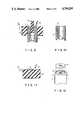
- FIG. 1is a schematic perspective view showing a part of an insertion section of an endoscope according to a first embodiment of the present invention
- FIG. 2is a schematic cross section of the insertion section shown in FIG. 1;
- FIG. 3is a schematic cross section of the insertion section, illustrating the state in which a resin layer is being formed in the insertion section of the endoscope of the first embodiment
- FIG. 4is a schematic perspective view showing, like FIG. 1, a part of an insertion section of an endoscope according to a second embodiment of the present invention
- FIG. 5is a schematic cross section of the insertion section shown in FIG. 4;
- FIG. 6is a schematic perspective view showing a part of an insertion section of an endoscope according to a third embodiment of the present invention.
- FIG. 7is a schematic cross section of the insertion section shown in FIG. 6;
- FIG. 8is a schematic cross section of the insertion section of an endoscope according to a fourth embodiment of the present invention.
- FIG. 9is a schematic view showing a first modification of the method of forming the resin layer in the first embodiment
- FIG. 10is a schematic view showing the resin layer formed by the method of FIG. 9, along with a portion of the light guide fiber bundle;
- FIG. 11is a schematic view showing a second modification of the method of forming the resin layer in the first embodiment
- FIG. 12is a schematic view showing the state in which the resin layer formed by the method of the second modification is mounted at an end portion of the insertion section;
- FIG. 13is a schematic longitudinal cross section of a part of an insertion section of an endoscope according to an example relating to the present invention.
- FIG. 14is a transverse cross section of the insertion section of the endoscope shown in FIG. 13;
- FIG. 15is a schematic longitudinal cross section of a part of an insertion section of an endoscope according to another example relating to the present invention.
- FIG. 16is a transverse cross section of the insertion section of the endoscope shown in FIG. 15.
- FIGS. 1, 2 and 3show a part of the endoscope according to the first embodiment of the present invention.
- the endoscopehas very thin insertion section 1, which can be inserted into a narrow body cavity such as a blood vessel. Insertion section 1 is connected to a control section (not shown).
- the outer periphery of insertion section 1is formed of hollow cylindrical thin sheath or cylindrical member 2.
- An outer edge portion of an insertion end portion or a distal end portion (the left side of FIG. 1) of sheath 2is smoothly curved, so that the insertion end portion may be easily inserted into the body cavity.
- hollow cylindrical lens frame 3is concentrically arranged within sheath 2. Axially inner and outer end portions of lens frame 3 are opened.
- the axially outer end portion of lens frame 3is substantially flush with plane A which includes the end face of sheath 2.
- Lens frame 3surrounds object lens group 4 which receives light beams incident from outside to form an image.
- the outer surface of the outermost lens of lens group 4is substantially flush with, or slightly projects from, plane A.
- Object lens group 4forms an image on the adjacent end face of fiber bundle 5.
- Light guide fiber bundle 6 for guiding illumination light from a light sourceis provided within a space defined by the inner periphery of sheath 2 and the outer periphery of lens frame 3.
- Fiber bundle 6is formed of a number of closely gathered glass fibers.
- End face 7 of light guide fiber bundle 6is arranged in a plane normal to the axis of insertion section 1.
- End face 7 of fiber bundle 6has an annular shape, when viewed from outside in the axial direction. Also, end face 7 is flush with plane B which is rearward of plane A by ⁇ 1.
- annular groove or annular recess portion 8which is open to the outside, is formed at the end portion of insertion section 1.
- Groove 8has the outer wall defined by the inner periphery of sheath 2, the inner wall defined by the outer periphery of lens frame 3, and the bottom wall defined by end face 7 of light guide fiber bundle 6.
- Groove 8is filled with transparent resin 9a such as epoxy adhesive (e.g., tradename "STYCAST 1266"). Resin 9a is filled and hardened, thereby forming transparent resin layer 9 having end face 10 flush with plane A.
- Illumination light supplied from the light source through light guide fiber bundle 6is transmitted through transparent resin layer 9 and emitted from insertion section 2 in the axial direction.
- a method of forming transparent resin layer 9may now be described.
- Object lens group 4 and image guide fiber bundle 5are fixed in a predetermined position within lens frame 3 by using an adhesive.
- Light guide fiber bundle 6is formed in a hollow cylindrical shape.
- Lens frame 3is inserted into a central space defined by the inner periphery of the end portion of fiber bundle 6.
- the end face of lens frame 3is projected from end face 7 of fiber bundle 6 by ⁇ 1.
- the combination of lens frame 3 and light guide fiber bundle 6is inserted into sheath 2, and is fixed therein in such a position that the end face of lens frame 3 is substantially flush with plane A of sheath 2.
- annular groove 8which is open at one axial end and is defined by sheath 2, lens frame 3 and end face 7 of light guide fiber bundle 6, is formed.
- fluidal epoxy resin adhesive 9ais filled in groove 8, so that no space remains in groove 8 and the thickness t of the resin material is ⁇ 1.
- Resin 9ais hardened to obtain resin layer 9 of a uniform thickness.
- resin layer 9having a uniform, minimum necessary thickness.
- non-uniformityappears in thickness of respective resin layers produced in a conventional method wherein resin is coated on the end face of a light guide fiber bundle.
- this conventional methodspecial skill is required to provide each endoscope with a uniform light transmission degree.
- each productcan be easily provided with resin layer 9 of a uniform thickness, simply by filling groove 8 of depth ⁇ 1 with resin 9a. By changing the depth ⁇ 1 of groove 8, resin layer 9 of an optimum thickness can be formed. Since resin layer 9 does not project from plane A, it can be protected against scars and shock.
- FIGS. 4 and 5The second embodiment shown in FIGS. 4 and 5 will now be described.
- the numerals already appearing in FIGS. 1-3indicate the same elements. The description of such elements may be omitted.
- the endoscopehas very thin insertion section 1 for observation of the inside of a blood vessel.
- insertion section 1Within insertion section 1, axially extending channel 11 is provided.
- Light guide fiber bundle 6is arranged within sheath 2, with axially extending cylindrical spaces 13 and 14 being formed.
- Space 13contains lens frame 3
- space 14contains hollow cylindrical tube 12 which defines forceps channel 11. Therefore, small space 13 and large space 14 appear in a transverse cross section of fiber bundle 6.
- End faces of tube 12 and lens frame 3are substantially flush with end face A of sheath 2.
- Recess portion 8is formed at the end portion (the left side of FIG. 4) of insertion section 1.
- the outer peripheral wall of recess portion 8is defined by the inner periphery of sheath 2, and the bottom wall of recess portion 8 is defined by end face 7 of light guide fiber bundle 6.
- Lens frame 8 and tube 12project from the bottom wall of recess portion 8.
- transparent resin layer 9is formed within recess portion 8. Since an end face of tube 12 is substantially flush with end face A of sheath 2, and end face 7 of light guide fiber bundle 6 is retreated from end face A of sheath 2, fluidal resin filled in recess portion 8 does not enter tube 12.
- insertion section 1is formed of a multi-lumen tube having a plurality of non-circular cross sectional spaces.
- the previously mentioned numeralsindicate the same elements, and the description of these elements may be omitted.
- Cylindrical member 2is an integral tube made of resin, and it has non-circular cross sectional spaces 11 and 12 and substantially circular cross sectional space 13.
- Space 11serves as a channel.
- Space 13contains, as in the first embodiment, lens frame 3, object lens group 4, and image guide fiber bundle 5.
- Space 12contains light guide fiber bundle 6.
- Space 12has at its end portion recess portion 8 having its peripheral wall defined by the inner wall of space 12 and its bottom wall defined by end face 7 of light guide fiber bundle 6.
- Transparent resin layer 9is formed in recess portion 8, in the same method as in the first embodiment.
- FIG. 8shows endoscope 1 according to the fourth embodiment, wherein the image guide fiber bundle is protected against damages.
- Endoscope 1is formed, in a similar method to that of the first embodiment.
- Image guide fiber bundle 5has hard cylindrical portion 5a formed by bonding a number of optical fibers by an adhesive or synthetic resin. At least an end portion of hard portion 5a is inserted into lens frame 3 to adjoin object optical system 4. An rear end portion of hard portion 5a is located outside the lens frame 3.
- the length of hard portion 5ais determined such that, when image guide fiber bundle 5 and lens frame 3 are assembled within sheath 2, distance L1 is kept between plane A and plane C normal to the axis of sheath 2 which includes the end face of hard portion 5a.
- Light guide fiber bundle 6has also hard portion 6a.
- the length of hard portion 6ais determined such that, when light guide fiber bundle 6 and resin layer 9 are assembled within sheath 2, distance L2 is kept between plane A and plane D normal to the axis of sheath 2 which includes the end face of hard portion 6a.
- L1 and L2The relationship between L1 and L2 is L1 ⁇ L2.
- hard portion 5a of image guide fiber bundle 5is surrounded by hard portion 6a of light guide fiber bundle 6.
- FIGS. 9 and 10show a modification of the method of forming the resin layer.
- a resin layeris formed on end face 7 of fiber bundle 6 in advance, and the fiber bundle 7 with the resin layer is inserted into the sheath.
- a cylindrical space for containing lens frame 3is formed at the end of light guide fiber bundle 6.
- the outer diameter of fiber bundle 6is set so that fiber bundle 6 may be fitted in sheath 2.
- fiber bundle 6is inserted into a hole in mold 20.
- the holehas the same inner diameter as sheath 2, and mold 20 is made of, for example, polytetrafluoroethylene (PTFE).
- End face 7 of fiber bundle 6is retreated from the end face of mold 20 (top face of mold 20 in FIG. 9) by ⁇ 1.
- Core mold 21, which is also made of PTFE and has the same diameter as lens frame 3,is inserted into the cylindrical space formed at the end portion of fiber bundle 6.
- resin 22(as mentioned above) is filled in an annular groove defined by mold 20, light guide fiber bundle 6 and core mold 21. Resin 22 is filled in the annular groove up to the same level as, or a little higher level than, the end face of mold 20. After resin 22 is hardened, core mold 21 is removed. The end face of mold 20 and the end face (top face in FIG. 9) of hardened resin 22 are polished so that they are made flush with one another. Then, fiber bundle 6 is drawn out of mold 20. Thus, as shown in FIG. 10, light guide fiber bundle 6, which has resin layer 9 of a uniform thickness at its end portion (upper portion in FIG. 10) can be obtained.
- the image guide fiber bundle having the object lens group, the lens frame, and the sheathare assembled.
- the end faces of lens frame 3 and sheath 2are made flush with a free face (top face in FIG. 10) of resin layer 9.
- resin layer 9 and light guide fiber bundle 6can be formed as a combination, before the fiber bundle, lens frame, object lens, and sheath are assembled.
- Resin layer 9can be polished safely and surely, without damaging other elements such as an object lens. Since resin layer 9 can be provided with a smooth free surface, stable light transmission is ensured. If a defect is found in resin layer 9, it is sufficient to dispose of light guide fiber bundle 6, without affecting other elements. Therefore, the structural elements of the endoscope can be efficiently used, and the total manufacturing cost can be reduced.
- FIGS. 11 and 12show the second modification of the method of manufacturing the resin layer.
- mold 30 of PTFEhas recess portion or annular groove 31 of a depth ⁇ 1.
- the upper end of groove 31is open to the outside.
- Resin 32(as mentioned above) is filled in groove 31.
- resin 32is filled in groove 31 up to the same level as, or a little higher level than, the end face (top face in FIG. 11) of mold 30.
- the end face (top face) of mold 30is polished to smooth the free surface of resin 32.
- Hollow cylindrical resin layer 9, having a small axial length,is removed from mold 30. Then, as shown in FIG. 12, resin layer 9 is mounted on the end portion of insertion section 1 constituted in advance by sheath 2, lens frame 3, object lens group 4, an image guide fiber bundle, and light guide fiber bundle 6.
- insertion section 1has at its end portion (top end in FIG. 12) annular groove 8 which has an outer peripheral wall defined by the inner wall of sheath 2, an inner peripheral wall defined by the outer wall of lens frame 3, and a bottom wall defined by end face 7 of light guide fiber bundle 6.
- the size of groove 8corresponds to that of resin layer 9 formed by the method shown in FIG. 11.
- An adhesive for attaching resin layer 9 to groove 8should be of the type similar to resin 32 or resin layer 9. (For example, when resin 32 is epoxy resin, the adhesive should be made of epoxy material.)
- Polytetrafluoroethylene(PTFE) is used as material of mold 20 of the first modification shown in FIG. 9, and mold 30 of the second modification shown in FIG. 11.
- PTFEPolytetrafluoroethylene
- other suitable resinscan be employed.
- FIGS. 13 and 14An endoscope shown in FIGS. 13 and 14, which is an example relating to the present invention, will now be described.
- This endoscopehas a very thin insertion section which can be inserted into, for example, a blood vessel. While the small diameter of the insertion section is maintained, a damage to optical fibers within the insertion section can be prevented.
- insertion section 1has an outer diameter which is allowed to enter the blood vessel.
- Sheath 2is made of resilient resin such as PTFE in a hollow cylindrical shape. The wall thickness of sheath 2 is small.
- Lens frame 3is arranged at a center area of sheath 2 in the vicinity of an end portion (left portion in FIG. 13) of insertion section 1.
- Object lens group 4having a cover glass and an object lens is secured within lens frame 3.
- Image guide fiber bundle 5has hard end portion 5a formed by connecting a number of optical fibers in a solid cylindrical shape by using an adhesive or synthetic resin. At least a part of hard end portion 5a is inserted into lens frame 3, and fixed at a predetermined position. The axial length of hard end portion 5a is determined such that, when hard end portion 5a is arranged at a predetermined position within lens frame 3, distance L1 is kept between plane C normal to the axis of insertion section 1 including rear end 15 and plane A normal to the axis of sheath 2 including its end face.
- Light guide fiber bundle 6which is arranged around lens frame 3 within sheath 2, is formed by bonding a number of optical fibers by an adhesive or synthetic resin.
- Fiber bundle 6has hollow cylindrical hard end portion 6a into which lens frame 3 can be inserted.
- the axial length of hard end portion 6ais determined such that, when hard end portion 6a is arranged at a predetermined position within sheath 2, distance L2 is kept between plane D normal to the axis of insertion section 1 including rear end 16 and plane A normal to the axis of sheath 2 including its end face.
- the inner peripheral surface of hard end portion 6ais attached on lens frame 3, and the outer peripheral surface of hard end portion 6a is attached on sheath 2.
- the lengths of image guide fiber bundle 5 and light guide fiber bundle 6are determined such that, when they are assembled within sheath 2, the relationship in length between hard end portions 5a and 6a becomes L1 ⁇ L2. Accordingly, at the end portion of insertion section 1, the entire length of hard end portion 5a of image guide fiber bundle 5 is covered by hard end portion 6a of light guide fiber bundle 6.
- Hard end portion 5a and hard rear edge 15 of image guide fiber bundle 5, which are protected by hard end portion 6a of light guide fiber bundle 6,are not damaged by external force due to shock or bending moment applied to the end portion of insertion section 1. While the outer diameter of insertion section 1 is limited to a small value, optical fibers of image guide fiber bundle 5 can be protected against external force, and high durability of the fibers is ensured.
- FIGS. 15 and 16show a second example relating to the present invention.
- forceps channel 11is formed within insertion section 1.
- axially extending cylindrical spaces 13 and 14are formed within hard end portion 6a of light guide fiber bundle 6, for containing lens frame 3 and tube 12 defining channel 11.
- the distance L1 between plane A including the end face of sheath 2 and plane C including rear edge 15 of hard end portion 5ais equal or smaller than the distance L2 between plane A and plane D including rear edge 16 of hard end portion 6a.
- end portion 5awhich is the weakest part of image guide fiber bundle 5, can be protected by hard end portion 6a of light guide fiber bundle 6.
- the endoscopes of the examples of FIGS. 13-14 and FIGS. 15-16may be provided with resin layers for sealing the inside of the sheaths, as mentioned above.
Landscapes
- Health & Medical Sciences (AREA)
- Life Sciences & Earth Sciences (AREA)
- Surgery (AREA)
- Physics & Mathematics (AREA)
- Engineering & Computer Science (AREA)
- Optics & Photonics (AREA)
- Biomedical Technology (AREA)
- Molecular Biology (AREA)
- Pathology (AREA)
- Nuclear Medicine, Radiotherapy & Molecular Imaging (AREA)
- Biophysics (AREA)
- Heart & Thoracic Surgery (AREA)
- Medical Informatics (AREA)
- Radiology & Medical Imaging (AREA)
- Animal Behavior & Ethology (AREA)
- General Health & Medical Sciences (AREA)
- Public Health (AREA)
- Veterinary Medicine (AREA)
- Manufacturing & Machinery (AREA)
- Endoscopes (AREA)
Abstract
Description
Claims (11)
Applications Claiming Priority (4)
| Application Number | Priority Date | Filing Date | Title |
|---|---|---|---|
| JP61297728AJPS63151918A (en) | 1986-12-16 | 1986-12-16 | Endoscope |
| JP61-297728 | 1986-12-16 | ||
| JP62067241AJPH0718979B2 (en) | 1987-03-20 | 1987-03-20 | Endoscope |
| JP62-67241 | 1987-03-20 |
Publications (1)
| Publication Number | Publication Date |
|---|---|
| US4790295Atrue US4790295A (en) | 1988-12-13 |
Family
ID=26408421
Family Applications (1)
| Application Number | Title | Priority Date | Filing Date |
|---|---|---|---|
| US07/130,090Expired - LifetimeUS4790295A (en) | 1986-12-16 | 1987-12-08 | Endoscope having transparent resin sealing layer |
Country Status (1)
| Country | Link |
|---|---|
| US (1) | US4790295A (en) |
Cited By (56)
| Publication number | Priority date | Publication date | Assignee | Title |
|---|---|---|---|---|
| WO1989012479A1 (en)* | 1988-06-16 | 1989-12-28 | Optimed Technologies, Inc. | Angioplasty catheter with integral fiber optic |
| US4945894A (en)* | 1988-10-18 | 1990-08-07 | Olympus Optical Co., Ltd. | Endoscope having X-ray non-transmitting material |
| US4979498A (en)* | 1989-10-30 | 1990-12-25 | Machida Incorporated | Video cervicoscope system |
| FR2651986A1 (en)* | 1989-09-20 | 1991-03-22 | Croisy Renaud | CATHETER FOR VISION IN A CONDUIT, ESPECIALLY A HUMAN BODY. |
| US5116317A (en)* | 1988-06-16 | 1992-05-26 | Optimed Technologies, Inc. | Angioplasty catheter with integral fiber optic assembly |
| US5121740A (en)* | 1991-05-06 | 1992-06-16 | Martin Uram | Laser video endoscope |
| US5199417A (en)* | 1990-12-21 | 1993-04-06 | Circon Corporation | Endoscope having a deflectable distal section and a semi-rigid proximal section |
| US5299560A (en)* | 1992-06-18 | 1994-04-05 | Olympus Optical Co., Ltd. | Endoscope in which a bend remaining in the insertion portion upon removal from storage is reduced |
| US5323766A (en)* | 1991-05-06 | 1994-06-28 | Endo Optiks Corporation | Illuminating endo-photocoagulation probe |
| US5335647A (en)* | 1992-06-26 | 1994-08-09 | Applied Medical Resources Corporation | Potted endoscope |
| US5377669A (en)* | 1992-04-06 | 1995-01-03 | Henke-Sass, Wolf Gmbh | Sapphire protective covering for medical endoscope |
| US5419313A (en)* | 1988-10-27 | 1995-05-30 | Rosemarie Lemke | Microwave sterilizable and reusable endoscope |
| EP0496110B1 (en)* | 1991-01-19 | 1997-03-05 | Olympus Winter & Ibe Gmbh | Endoscope for transurethral operation |
| US5810713A (en)* | 1996-07-10 | 1998-09-22 | Valquest Medical, Inc. | Autoclavable endoscope |
| US5954637A (en)* | 1995-10-20 | 1999-09-21 | United States Surgical Corporation | Laparoscope |
| US6004263A (en)* | 1996-03-13 | 1999-12-21 | Hihon Kohden Corporation | Endoscope with detachable operation unit and insertion unit |
| US6129662A (en)* | 1996-06-03 | 2000-10-10 | Cogent Light Technologies, Inc. | Surgical tool with surgical field illuminator |
| US6206825B1 (en)* | 1995-06-29 | 2001-03-27 | Olympus Optical Co., Ltd. | Illumination system for endoscopes and an endoscope having the illumination system |
| US6293910B1 (en)* | 1997-02-13 | 2001-09-25 | Matsushita Electric Industrial Co., Ltd. | Endoscope, method of manufacturing the same, and insertion member |
| US20030083552A1 (en)* | 2001-10-19 | 2003-05-01 | Visionscope, Inc. | Miniature endoscope with imaging fiber system |
| US20030163030A1 (en)* | 2002-02-25 | 2003-08-28 | Arriaga Moises A. | Hollow endoscopy |
| US20040015138A1 (en)* | 2002-07-16 | 2004-01-22 | Clifford Currier | Multiple lumen catheter having a soft tip |
| US20040015061A1 (en)* | 2002-07-16 | 2004-01-22 | Clifford Currier | Central venous catheter having a soft tip and fiber optics |
| US20040158129A1 (en)* | 2003-02-10 | 2004-08-12 | Pentax Corporation | Endoscope |
| US20050250992A1 (en)* | 2004-05-06 | 2005-11-10 | Olympus Winter & Ibe Gmbh | Endoscope optics with a lateral optic-fiber bundle |
| US20060009740A1 (en)* | 2001-08-28 | 2006-01-12 | Michael Higgins | Multiple lumen catheter having a soft tip |
| US20060030753A1 (en)* | 2004-08-09 | 2006-02-09 | Scimed Life Systems, Inc. | Fiber optic imaging catheter |
| DE102005051209A1 (en)* | 2005-10-18 | 2007-04-19 | Karl Storz Gmbh & Co. Kg | Endoscope consists of a shaft with outer and inner pipe that house a shorter intermediate pipe and has channel to hold fibre optic |
| US20080044146A1 (en)* | 2006-06-30 | 2008-02-21 | Michael Weisser | Illuminable image-conducting optical assembly including light-conductive optics housing for creating an illuminating halo |
| US20080069500A1 (en)* | 2006-09-18 | 2008-03-20 | Weston Lee Harness | Fiber optic overmold method and product |
| US20090253967A1 (en)* | 2001-10-19 | 2009-10-08 | Visionscope Technologies, Llc | Portable imaging system employing a miniature endoscope |
| US7603013B1 (en)* | 2008-04-15 | 2009-10-13 | University Of Iowa Research Foundation | Fiberscopes and fiber bundles |
| US20100160754A1 (en)* | 2008-12-23 | 2010-06-24 | The Regents Of The University Of California | Method and Apparatus for Quantification of Optical Properties of Superficial Volumes Using Small Source-to-Detector Separations |
| US20110082449A1 (en)* | 2009-10-02 | 2011-04-07 | Cardiofocus, Inc. | Cardiac ablation system with pulsed aiming light |
| US8038602B2 (en) | 2001-10-19 | 2011-10-18 | Visionscope Llc | Portable imaging system employing a miniature endoscope |
| US8182422B2 (en)* | 2005-12-13 | 2012-05-22 | Avantis Medical Systems, Inc. | Endoscope having detachable imaging device and method of using |
| US8197399B2 (en) | 2006-05-19 | 2012-06-12 | Avantis Medical Systems, Inc. | System and method for producing and improving images |
| US8235887B2 (en) | 2006-01-23 | 2012-08-07 | Avantis Medical Systems, Inc. | Endoscope assembly with retroscope |
| US8287446B2 (en) | 2006-04-18 | 2012-10-16 | Avantis Medical Systems, Inc. | Vibratory device, endoscope having such a device, method for configuring an endoscope, and method of reducing looping of an endoscope |
| US8289381B2 (en) | 2005-01-05 | 2012-10-16 | Avantis Medical Systems, Inc. | Endoscope with an imaging catheter assembly and method of configuring an endoscope |
| US8317689B1 (en)* | 1999-09-13 | 2012-11-27 | Visionscope Technologies Llc | Miniature endoscope system |
| WO2012116169A3 (en)* | 2011-02-23 | 2013-02-21 | Intuitive Surgical Operations, Inc. | Maximizing illumination fiber in an endoscope |
| US8608649B2 (en) | 2004-03-23 | 2013-12-17 | Boston Scientific Scimed, Inc. | In-vivo visualization system |
| US8797392B2 (en) | 2005-01-05 | 2014-08-05 | Avantis Medical Sytems, Inc. | Endoscope assembly with a polarizing filter |
| US8872906B2 (en) | 2005-01-05 | 2014-10-28 | Avantis Medical Systems, Inc. | Endoscope assembly with a polarizing filter |
| US9044185B2 (en) | 2007-04-10 | 2015-06-02 | Avantis Medical Systems, Inc. | Method and device for examining or imaging an interior surface of a cavity |
| CN106999013A (en)* | 2015-08-05 | 2017-08-01 | 奥林巴斯株式会社 | Image unit and endoscope |
| US20180081165A1 (en)* | 2016-08-31 | 2018-03-22 | Schott Ag | Illumination system comprising heterogeneous fiber arrangement |
| US10531787B2 (en) | 2016-07-28 | 2020-01-14 | Cook Medical Technologies Llc | Steerable multilumen catheter shaft |
| US10595710B2 (en) | 2001-10-19 | 2020-03-24 | Visionscope Technologies Llc | Portable imaging system employing a miniature endoscope |
| US10994076B1 (en) | 2019-07-25 | 2021-05-04 | Circulatech, Llc | Methods and devices to prevent obstructions in medical tubes |
| US11259694B2 (en) | 2019-01-31 | 2022-03-01 | Canon U.S.A., Inc. | Window assembly for endoscopic probe |
| US11337598B2 (en) | 2010-05-13 | 2022-05-24 | Beaver-Visitec International, Inc. | Laser video endoscope |
| WO2022133214A1 (en)* | 2020-12-18 | 2022-06-23 | Precision Optics Corporation, Inc. | System and method for treating ends of optical fibers for use in an endoscope |
| US11819192B2 (en) | 2004-03-23 | 2023-11-21 | Boston Scientific Scimed, Inc. | In-vivo visualization system |
| DE102009056499B4 (en) | 2008-12-05 | 2023-12-07 | Medical Intubation Technology Corporation | Miniature camera |
Citations (7)
| Publication number | Priority date | Publication date | Assignee | Title |
|---|---|---|---|---|
| US4273109A (en)* | 1976-07-06 | 1981-06-16 | Cavitron Corporation | Fiber optic light delivery apparatus and medical instrument utilizing same |
| US4350150A (en)* | 1979-09-25 | 1982-09-21 | Olympus Optical Co., Ltd. | Structure of a light-receiving end portion of an endoscope light guide |
| JPS6114312A (en)* | 1984-06-27 | 1986-01-22 | 伊徳 行 | Mark body for boundary |
| JPS6120371A (en)* | 1984-07-06 | 1986-01-29 | Sanyo Electric Co Ltd | photovoltaic device |
| US4576146A (en)* | 1983-03-22 | 1986-03-18 | Sumitomo Electric Industries, Ltd. | Fiberscope |
| US4587972A (en)* | 1984-07-16 | 1986-05-13 | Morantte Jr Bernardo D | Device for diagnostic and therapeutic intravascular intervention |
| JPS6284012A (en)* | 1985-10-07 | 1987-04-17 | Shiseido Co Ltd | Hair tonic |
- 1987
- 1987-12-08USUS07/130,090patent/US4790295A/ennot_activeExpired - Lifetime
Patent Citations (7)
| Publication number | Priority date | Publication date | Assignee | Title |
|---|---|---|---|---|
| US4273109A (en)* | 1976-07-06 | 1981-06-16 | Cavitron Corporation | Fiber optic light delivery apparatus and medical instrument utilizing same |
| US4350150A (en)* | 1979-09-25 | 1982-09-21 | Olympus Optical Co., Ltd. | Structure of a light-receiving end portion of an endoscope light guide |
| US4576146A (en)* | 1983-03-22 | 1986-03-18 | Sumitomo Electric Industries, Ltd. | Fiberscope |
| JPS6114312A (en)* | 1984-06-27 | 1986-01-22 | 伊徳 行 | Mark body for boundary |
| JPS6120371A (en)* | 1984-07-06 | 1986-01-29 | Sanyo Electric Co Ltd | photovoltaic device |
| US4587972A (en)* | 1984-07-16 | 1986-05-13 | Morantte Jr Bernardo D | Device for diagnostic and therapeutic intravascular intervention |
| JPS6284012A (en)* | 1985-10-07 | 1987-04-17 | Shiseido Co Ltd | Hair tonic |
Cited By (97)
| Publication number | Priority date | Publication date | Assignee | Title |
|---|---|---|---|---|
| US5116317A (en)* | 1988-06-16 | 1992-05-26 | Optimed Technologies, Inc. | Angioplasty catheter with integral fiber optic assembly |
| WO1989012479A1 (en)* | 1988-06-16 | 1989-12-28 | Optimed Technologies, Inc. | Angioplasty catheter with integral fiber optic |
| US4945894A (en)* | 1988-10-18 | 1990-08-07 | Olympus Optical Co., Ltd. | Endoscope having X-ray non-transmitting material |
| US5419313A (en)* | 1988-10-27 | 1995-05-30 | Rosemarie Lemke | Microwave sterilizable and reusable endoscope |
| EP0419343A1 (en)* | 1989-09-20 | 1991-03-27 | Renaud Croisy | Catheter for viewing in a duct, particularly of the human body |
| FR2651986A1 (en)* | 1989-09-20 | 1991-03-22 | Croisy Renaud | CATHETER FOR VISION IN A CONDUIT, ESPECIALLY A HUMAN BODY. |
| US4979498A (en)* | 1989-10-30 | 1990-12-25 | Machida Incorporated | Video cervicoscope system |
| US5199417A (en)* | 1990-12-21 | 1993-04-06 | Circon Corporation | Endoscope having a deflectable distal section and a semi-rigid proximal section |
| EP0496110B1 (en)* | 1991-01-19 | 1997-03-05 | Olympus Winter & Ibe Gmbh | Endoscope for transurethral operation |
| US5121740A (en)* | 1991-05-06 | 1992-06-16 | Martin Uram | Laser video endoscope |
| US5323766A (en)* | 1991-05-06 | 1994-06-28 | Endo Optiks Corporation | Illuminating endo-photocoagulation probe |
| US5377669A (en)* | 1992-04-06 | 1995-01-03 | Henke-Sass, Wolf Gmbh | Sapphire protective covering for medical endoscope |
| US5299560A (en)* | 1992-06-18 | 1994-04-05 | Olympus Optical Co., Ltd. | Endoscope in which a bend remaining in the insertion portion upon removal from storage is reduced |
| US5335647A (en)* | 1992-06-26 | 1994-08-09 | Applied Medical Resources Corporation | Potted endoscope |
| US6206825B1 (en)* | 1995-06-29 | 2001-03-27 | Olympus Optical Co., Ltd. | Illumination system for endoscopes and an endoscope having the illumination system |
| US5954637A (en)* | 1995-10-20 | 1999-09-21 | United States Surgical Corporation | Laparoscope |
| US6004263A (en)* | 1996-03-13 | 1999-12-21 | Hihon Kohden Corporation | Endoscope with detachable operation unit and insertion unit |
| US6129662A (en)* | 1996-06-03 | 2000-10-10 | Cogent Light Technologies, Inc. | Surgical tool with surgical field illuminator |
| US5810713A (en)* | 1996-07-10 | 1998-09-22 | Valquest Medical, Inc. | Autoclavable endoscope |
| US6293910B1 (en)* | 1997-02-13 | 2001-09-25 | Matsushita Electric Industrial Co., Ltd. | Endoscope, method of manufacturing the same, and insertion member |
| US8317689B1 (en)* | 1999-09-13 | 2012-11-27 | Visionscope Technologies Llc | Miniature endoscope system |
| US20060009740A1 (en)* | 2001-08-28 | 2006-01-12 | Michael Higgins | Multiple lumen catheter having a soft tip |
| US20030083552A1 (en)* | 2001-10-19 | 2003-05-01 | Visionscope, Inc. | Miniature endoscope with imaging fiber system |
| US11484189B2 (en)* | 2001-10-19 | 2022-11-01 | Visionscope Technologies Llc | Portable imaging system employing a miniature endoscope |
| US20090253967A1 (en)* | 2001-10-19 | 2009-10-08 | Visionscope Technologies, Llc | Portable imaging system employing a miniature endoscope |
| US10595710B2 (en) | 2001-10-19 | 2020-03-24 | Visionscope Technologies Llc | Portable imaging system employing a miniature endoscope |
| US6863651B2 (en)* | 2001-10-19 | 2005-03-08 | Visionscope, Llc | Miniature endoscope with imaging fiber system |
| US20060015014A1 (en)* | 2001-10-19 | 2006-01-19 | Paul Remijan | Miniature endoscope with imaging fiber system |
| US8038602B2 (en) | 2001-10-19 | 2011-10-18 | Visionscope Llc | Portable imaging system employing a miniature endoscope |
| US7942814B2 (en)* | 2001-10-19 | 2011-05-17 | Visionscope Technologies Llc | Miniature endoscope with imaging fiber system |
| US20030163030A1 (en)* | 2002-02-25 | 2003-08-28 | Arriaga Moises A. | Hollow endoscopy |
| US20040015061A1 (en)* | 2002-07-16 | 2004-01-22 | Clifford Currier | Central venous catheter having a soft tip and fiber optics |
| US20040015138A1 (en)* | 2002-07-16 | 2004-01-22 | Clifford Currier | Multiple lumen catheter having a soft tip |
| US6999809B2 (en) | 2002-07-16 | 2006-02-14 | Edwards Lifesciences Corporation | Central venous catheter having a soft tip and fiber optics |
| US7029467B2 (en) | 2002-07-16 | 2006-04-18 | Edwards Lifesciences Corporation | Multiple lumen catheter having a soft tip |
| US20040158129A1 (en)* | 2003-02-10 | 2004-08-12 | Pentax Corporation | Endoscope |
| US7267647B2 (en)* | 2003-02-10 | 2007-09-11 | Pentax Corporation | Endoscope |
| US11819192B2 (en) | 2004-03-23 | 2023-11-21 | Boston Scientific Scimed, Inc. | In-vivo visualization system |
| US11064869B2 (en) | 2004-03-23 | 2021-07-20 | Boston Scientific Scimed, Inc. | In-vivo visualization system |
| US8608649B2 (en) | 2004-03-23 | 2013-12-17 | Boston Scientific Scimed, Inc. | In-vivo visualization system |
| US9339173B2 (en) | 2004-03-23 | 2016-05-17 | Boston Scientific Scimed, Inc. | In-vivo visualization system |
| US11832793B2 (en) | 2004-03-23 | 2023-12-05 | Boston Scientific Scimed, Inc. | Vivo visualization system |
| US12213650B2 (en) | 2004-03-23 | 2025-02-04 | Boston Scientific Scimed, Inc. | In-vivo visualization system |
| US20050250992A1 (en)* | 2004-05-06 | 2005-11-10 | Olympus Winter & Ibe Gmbh | Endoscope optics with a lateral optic-fiber bundle |
| US7569013B2 (en)* | 2004-05-06 | 2009-08-04 | Olympus Winter & Ibe Gmbh | Endoscope optics with a lateral optic-fiber bundle |
| US10058236B2 (en) | 2004-08-09 | 2018-08-28 | Boston Scientific Scimed, Inc. | Fiber optic imaging catheter |
| US7922654B2 (en)* | 2004-08-09 | 2011-04-12 | Boston Scientific Scimed, Inc. | Fiber optic imaging catheter |
| US20060030753A1 (en)* | 2004-08-09 | 2006-02-09 | Scimed Life Systems, Inc. | Fiber optic imaging catheter |
| US9215970B2 (en) | 2004-08-09 | 2015-12-22 | Boston Scientific Scimed, Inc. | Fiber optic imaging catheter |
| US8289381B2 (en) | 2005-01-05 | 2012-10-16 | Avantis Medical Systems, Inc. | Endoscope with an imaging catheter assembly and method of configuring an endoscope |
| US8872906B2 (en) | 2005-01-05 | 2014-10-28 | Avantis Medical Systems, Inc. | Endoscope assembly with a polarizing filter |
| US8797392B2 (en) | 2005-01-05 | 2014-08-05 | Avantis Medical Sytems, Inc. | Endoscope assembly with a polarizing filter |
| US20070118014A1 (en)* | 2005-10-18 | 2007-05-24 | Frank Fuerst | Endoscope |
| DE102005051209A1 (en)* | 2005-10-18 | 2007-04-19 | Karl Storz Gmbh & Co. Kg | Endoscope consists of a shaft with outer and inner pipe that house a shorter intermediate pipe and has channel to hold fibre optic |
| EP1776917A1 (en)* | 2005-10-18 | 2007-04-25 | Karl Storz GmbH & Co. KG | Endoscope |
| US8394014B2 (en) | 2005-10-18 | 2013-03-12 | Karl Storz Gmbh & Co. Kg | Endoscope |
| US11529044B2 (en) | 2005-12-13 | 2022-12-20 | Psip Llc | Endoscope imaging device |
| US8182422B2 (en)* | 2005-12-13 | 2012-05-22 | Avantis Medical Systems, Inc. | Endoscope having detachable imaging device and method of using |
| US8235887B2 (en) | 2006-01-23 | 2012-08-07 | Avantis Medical Systems, Inc. | Endoscope assembly with retroscope |
| US10045685B2 (en) | 2006-01-23 | 2018-08-14 | Avantis Medical Systems, Inc. | Endoscope |
| US8287446B2 (en) | 2006-04-18 | 2012-10-16 | Avantis Medical Systems, Inc. | Vibratory device, endoscope having such a device, method for configuring an endoscope, and method of reducing looping of an endoscope |
| US8587645B2 (en) | 2006-05-19 | 2013-11-19 | Avantis Medical Systems, Inc. | Device and method for reducing effects of video artifacts |
| US8310530B2 (en) | 2006-05-19 | 2012-11-13 | Avantis Medical Systems, Inc. | Device and method for reducing effects of video artifacts |
| US8197399B2 (en) | 2006-05-19 | 2012-06-12 | Avantis Medical Systems, Inc. | System and method for producing and improving images |
| US20080044146A1 (en)* | 2006-06-30 | 2008-02-21 | Michael Weisser | Illuminable image-conducting optical assembly including light-conductive optics housing for creating an illuminating halo |
| WO2008005342A3 (en)* | 2006-06-30 | 2008-04-17 | Schott Corp | Image-conducting optical assembly including light-conductive optics housing |
| CN101506704B (en)* | 2006-06-30 | 2012-07-11 | 肖特公司 | Image-conducting optical assembly including light-conducting optics housing |
| EP2038688A4 (en)* | 2006-06-30 | 2012-06-27 | Schott Corp | Image-conducting optical assembly including light-conductive optics housing |
| US7583876B2 (en)* | 2006-06-30 | 2009-09-01 | Schott Corporation | Illuminable image-conducting optical assembly including light-conductive optics housing for creating an illuminating halo |
| US20080069500A1 (en)* | 2006-09-18 | 2008-03-20 | Weston Lee Harness | Fiber optic overmold method and product |
| US7412130B2 (en)* | 2006-09-18 | 2008-08-12 | X-Rite, Inc. | Fiber optic overmold method and product |
| US10354382B2 (en) | 2007-04-10 | 2019-07-16 | Avantis Medical Systems, Inc. | Method and device for examining or imaging an interior surface of a cavity |
| US9044185B2 (en) | 2007-04-10 | 2015-06-02 | Avantis Medical Systems, Inc. | Method and device for examining or imaging an interior surface of a cavity |
| US9613418B2 (en) | 2007-04-10 | 2017-04-04 | Avantis Medical Systems, Inc. | Method and device for examining or imaging an interior surface of a cavity |
| US7603013B1 (en)* | 2008-04-15 | 2009-10-13 | University Of Iowa Research Foundation | Fiberscopes and fiber bundles |
| US20090257723A1 (en)* | 2008-04-15 | 2009-10-15 | University Of Iowa Research Foundation | Fiberscopes and fiber bundles |
| DE102009056499B4 (en) | 2008-12-05 | 2023-12-07 | Medical Intubation Technology Corporation | Miniature camera |
| US8301216B2 (en)* | 2008-12-23 | 2012-10-30 | The Regents Of The University Of California | Method and apparatus for quantification of optical properties of superficial volumes using small source-to-detector separations |
| US20100160754A1 (en)* | 2008-12-23 | 2010-06-24 | The Regents Of The University Of California | Method and Apparatus for Quantification of Optical Properties of Superficial Volumes Using Small Source-to-Detector Separations |
| US8696653B2 (en)* | 2009-10-02 | 2014-04-15 | Cardiofocus, Inc. | Cardiac ablation system with pulsed aiming light |
| US20110082449A1 (en)* | 2009-10-02 | 2011-04-07 | Cardiofocus, Inc. | Cardiac ablation system with pulsed aiming light |
| US11337598B2 (en) | 2010-05-13 | 2022-05-24 | Beaver-Visitec International, Inc. | Laser video endoscope |
| WO2012116169A3 (en)* | 2011-02-23 | 2013-02-21 | Intuitive Surgical Operations, Inc. | Maximizing illumination fiber in an endoscope |
| EP2677919A4 (en)* | 2011-02-23 | 2017-08-30 | Intuitive Surgical Operations, Inc. | Maximizing illumination fiber in an endoscope |
| US10935781B2 (en) | 2011-02-23 | 2021-03-02 | Intuitive Surgical Operations, Inc. | Maximizing illumination fiber in an endoscope |
| CN103347434A (en)* | 2011-02-23 | 2013-10-09 | 直观外科手术操作公司 | Maximizing illumination fiber in an endoscope |
| CN103347434B (en)* | 2011-02-23 | 2016-08-10 | 直观外科手术操作公司 | The lighting fiber in endoscope is made to maximize |
| US10031330B2 (en) | 2011-02-23 | 2018-07-24 | Intuitive Surgical Operations, Inc. | Maximizing illumination fiber in an endoscope |
| CN106999013B (en)* | 2015-08-05 | 2018-12-14 | 奥林巴斯株式会社 | Camera unit and endoscope |
| CN106999013A (en)* | 2015-08-05 | 2017-08-01 | 奥林巴斯株式会社 | Image unit and endoscope |
| US10531787B2 (en) | 2016-07-28 | 2020-01-14 | Cook Medical Technologies Llc | Steerable multilumen catheter shaft |
| US10254535B2 (en)* | 2016-08-31 | 2019-04-09 | Schott Ag | Illumination system comprising heterogeneous fiber arrangement |
| US20180081165A1 (en)* | 2016-08-31 | 2018-03-22 | Schott Ag | Illumination system comprising heterogeneous fiber arrangement |
| US11259694B2 (en) | 2019-01-31 | 2022-03-01 | Canon U.S.A., Inc. | Window assembly for endoscopic probe |
| US10994076B1 (en) | 2019-07-25 | 2021-05-04 | Circulatech, Llc | Methods and devices to prevent obstructions in medical tubes |
| US12005232B1 (en) | 2019-07-25 | 2024-06-11 | CirculaTech LLC | Methods and devices to prevent obstructions in medical tubes |
| WO2022133214A1 (en)* | 2020-12-18 | 2022-06-23 | Precision Optics Corporation, Inc. | System and method for treating ends of optical fibers for use in an endoscope |
Similar Documents
| Publication | Publication Date | Title |
|---|---|---|
| US4790295A (en) | Endoscope having transparent resin sealing layer | |
| EP0188273B1 (en) | Fiberscope | |
| US4784144A (en) | Optical fiber image sensor | |
| US4805598A (en) | Endoscope having optical elements that are resistant to condensation | |
| US5840014A (en) | Endoscope | |
| US4772093A (en) | Fiber-optic image-carrying device | |
| US5993382A (en) | Lighted catheter device and method for use and manufacture thereof | |
| US6152872A (en) | Relay lens assembly for a disposable arthroscope | |
| US4778247A (en) | Molded objective head for fiberscopes with integral lenses | |
| US4826280A (en) | Grooved optical transmission channel | |
| US4942867A (en) | Distal end part of endoscope | |
| US5347988A (en) | Endoscope coupler with liquid interface | |
| US7985178B2 (en) | Endoscope and method for its manufacturing | |
| AU664070B2 (en) | Method for manufacturing a disposable arthroscopic probe | |
| US5030000A (en) | Fiber optic probe for measuring reflectance spectrum | |
| CN113384227A (en) | Endoscope and disposable endoscope system | |
| US11992190B2 (en) | Flexible endoscope based upon an investment composition | |
| JP2949653B2 (en) | Hard image scope | |
| EP0161834A1 (en) | Objective head for fibrescopes | |
| US6917738B2 (en) | Optical fiber system with sealed fiber bundle | |
| EP1662967A1 (en) | Endoscope | |
| CA1275589C (en) | Fiber-optic image-carrying device | |
| JPS5928122A (en) | Image observing part | |
| JPH055530Y2 (en) | ||
| JPH0363377B2 (en) |
Legal Events
| Date | Code | Title | Description |
|---|---|---|---|
| AS | Assignment | Owner name:OLYMPUS OPTICAL CO., LTD., 43-2, 2-CHOME, HATAGAYA Free format text:ASSIGNMENT OF ASSIGNORS INTEREST.;ASSIGNOR:TASHIRO, YOSHIO;REEL/FRAME:004799/0667 Effective date:19871127 Owner name:OLYMPUS OPTICAL CO., LTD., 43-2, 2-CHOME, HATAGAYA Free format text:ASSIGNMENT OF ASSIGNORS INTEREST;ASSIGNOR:TASHIRO, YOSHIO;REEL/FRAME:004799/0667 Effective date:19871127 | |
| STCF | Information on status: patent grant | Free format text:PATENTED CASE | |
| FEPP | Fee payment procedure | Free format text:PAYOR NUMBER ASSIGNED (ORIGINAL EVENT CODE: ASPN); ENTITY STATUS OF PATENT OWNER: LARGE ENTITY | |
| FPAY | Fee payment | Year of fee payment:4 | |
| FEPP | Fee payment procedure | Free format text:PAYER NUMBER DE-ASSIGNED (ORIGINAL EVENT CODE: RMPN); ENTITY STATUS OF PATENT OWNER: LARGE ENTITY Free format text:PAYOR NUMBER ASSIGNED (ORIGINAL EVENT CODE: ASPN); ENTITY STATUS OF PATENT OWNER: LARGE ENTITY | |
| FPAY | Fee payment | Year of fee payment:8 | |
| FPAY | Fee payment | Year of fee payment:12 |