US4789989A - Solar simulator employing flexible-optics - Google Patents
Solar simulator employing flexible-opticsDownload PDFInfo
- Publication number
- US4789989A US4789989AUS07/101,533US10153387AUS4789989AUS 4789989 AUS4789989 AUS 4789989AUS 10153387 AUS10153387 AUS 10153387AUS 4789989 AUS4789989 AUS 4789989A
- Authority
- US
- United States
- Prior art keywords
- high intensity
- light
- light source
- illumination guide
- intensity light
- Prior art date
- Legal status (The legal status is an assumption and is not a legal conclusion. Google has not performed a legal analysis and makes no representation as to the accuracy of the status listed.)
- Expired - Fee Related
Links
- 239000000835fiberSubstances0.000claimsabstractdescription24
- 238000012360testing methodMethods0.000claimsabstractdescription14
- 230000003595spectral effectEffects0.000claimsabstractdescription9
- 239000007788liquidSubstances0.000claimsabstractdescription4
- 238000005286illuminationMethods0.000claimsdescription14
- VYPSYNLAJGMNEJ-UHFFFAOYSA-NSilicium dioxideChemical groupO=[Si]=OVYPSYNLAJGMNEJ-UHFFFAOYSA-N0.000claimsdescription6
- 229910052724xenonInorganic materials0.000claimsdescription5
- FHNFHKCVQCLJFQ-UHFFFAOYSA-Nxenon atomChemical compound[Xe]FHNFHKCVQCLJFQ-UHFFFAOYSA-N0.000claimsdescription5
- 239000012530fluidSubstances0.000claimsdescription3
- 229920001296polysiloxanePolymers0.000claimsdescription2
- 239000000377silicon dioxideSubstances0.000claimsdescription2
- 230000007704transitionEffects0.000claims2
- 239000012141concentrateSubstances0.000claims1
- 238000001228spectrumMethods0.000description14
- 238000010521absorption reactionMethods0.000description6
- 238000005259measurementMethods0.000description4
- 238000012546transferMethods0.000description3
- CURLTUGMZLYLDI-UHFFFAOYSA-NCarbon dioxideChemical compoundO=C=OCURLTUGMZLYLDI-UHFFFAOYSA-N0.000description2
- 230000000694effectsEffects0.000description2
- 238000001914filtrationMethods0.000description2
- 230000003287optical effectEffects0.000description2
- 239000007787solidSubstances0.000description2
- CBENFWSGALASAD-UHFFFAOYSA-NOzoneChemical compound[O-][O+]=OCBENFWSGALASAD-UHFFFAOYSA-N0.000description1
- 230000004071biological effectEffects0.000description1
- 230000005540biological transmissionEffects0.000description1
- 229910002092carbon dioxideInorganic materials0.000description1
- 239000001569carbon dioxideSubstances0.000description1
- 238000005253claddingMethods0.000description1
- 239000003086colorantSubstances0.000description1
- 239000000470constituentSubstances0.000description1
- 238000010276constructionMethods0.000description1
- 238000005516engineering processMethods0.000description1
- 238000005562fadingMethods0.000description1
- 238000010438heat treatmentMethods0.000description1
- 238000011835investigationMethods0.000description1
- 238000012423maintenanceMethods0.000description1
- 239000000463materialSubstances0.000description1
- 238000012986modificationMethods0.000description1
- 230000004048modificationEffects0.000description1
- 239000000049pigmentSubstances0.000description1
- 230000005855radiationEffects0.000description1
- 238000004088simulationMethods0.000description1
- XLYOFNOQVPJJNP-UHFFFAOYSA-NwaterChemical compoundOXLYOFNOQVPJJNP-UHFFFAOYSA-N0.000description1
Images

Classifications
- F—MECHANICAL ENGINEERING; LIGHTING; HEATING; WEAPONS; BLASTING
- F21—LIGHTING
- F21S—NON-PORTABLE LIGHTING DEVICES; SYSTEMS THEREOF; VEHICLE LIGHTING DEVICES SPECIALLY ADAPTED FOR VEHICLE EXTERIORS
- F21S8/00—Lighting devices intended for fixed installation
- F21S8/006—Solar simulators, e.g. for testing photovoltaic panels
- G—PHYSICS
- G02—OPTICS
- G02B—OPTICAL ELEMENTS, SYSTEMS OR APPARATUS
- G02B6/00—Light guides; Structural details of arrangements comprising light guides and other optical elements, e.g. couplings
- G02B6/24—Coupling light guides
- G02B6/26—Optical coupling means
- G02B6/28—Optical coupling means having data bus means, i.e. plural waveguides interconnected and providing an inherently bidirectional system by mixing and splitting signals
- G02B6/2804—Optical coupling means having data bus means, i.e. plural waveguides interconnected and providing an inherently bidirectional system by mixing and splitting signals forming multipart couplers without wavelength selective elements, e.g. "T" couplers, star couplers
- G—PHYSICS
- G02—OPTICS
- G02B—OPTICAL ELEMENTS, SYSTEMS OR APPARATUS
- G02B6/00—Light guides; Structural details of arrangements comprising light guides and other optical elements, e.g. couplings
- G02B6/24—Coupling light guides
- G02B6/42—Coupling light guides with opto-electronic elements
- G02B6/4201—Packages, e.g. shape, construction, internal or external details
- G02B6/4202—Packages, e.g. shape, construction, internal or external details for coupling an active element with fibres without intermediate optical elements, e.g. fibres with plane ends, fibres with shaped ends, bundles
- G—PHYSICS
- G02—OPTICS
- G02B—OPTICAL ELEMENTS, SYSTEMS OR APPARATUS
- G02B6/00—Light guides; Structural details of arrangements comprising light guides and other optical elements, e.g. couplings
- G02B6/24—Coupling light guides
- G02B6/42—Coupling light guides with opto-electronic elements
- G02B6/4201—Packages, e.g. shape, construction, internal or external details
- G02B6/4204—Packages, e.g. shape, construction, internal or external details the coupling comprising intermediate optical elements, e.g. lenses, holograms
- G02B6/4206—Optical features
- G—PHYSICS
- G02—OPTICS
- G02B—OPTICAL ELEMENTS, SYSTEMS OR APPARATUS
- G02B6/00—Light guides; Structural details of arrangements comprising light guides and other optical elements, e.g. couplings
- G02B6/24—Coupling light guides
- G02B6/42—Coupling light guides with opto-electronic elements
- G02B6/4298—Coupling light guides with opto-electronic elements coupling with non-coherent light sources and/or radiation detectors, e.g. lamps, incandescent bulbs, scintillation chambers
- Y—GENERAL TAGGING OF NEW TECHNOLOGICAL DEVELOPMENTS; GENERAL TAGGING OF CROSS-SECTIONAL TECHNOLOGIES SPANNING OVER SEVERAL SECTIONS OF THE IPC; TECHNICAL SUBJECTS COVERED BY FORMER USPC CROSS-REFERENCE ART COLLECTIONS [XRACs] AND DIGESTS
- Y10—TECHNICAL SUBJECTS COVERED BY FORMER USPC
- Y10S—TECHNICAL SUBJECTS COVERED BY FORMER USPC CROSS-REFERENCE ART COLLECTIONS [XRACs] AND DIGESTS
- Y10S385/00—Optical waveguides
- Y10S385/90—Solar collector or transmitter
Definitions
- the inventionis directed to solar simulators and more particularly to a high efficiency solar simulators employing flexible optic technology to transfer simulated sunlight from a high intensity source to an enclosure and illuminating a test specimen with the light from the source either by flood illuminating the test specimen or by first collimating the light and then directing the collimated light on to the specimen.
- the earth's atmospherecreates substantial loss due to absorption and scattering throughout the spectrum.
- the absorptionis particularly strong in the shortwave ultraviolet, due primarily to ozone; and in the longer-wave infrared, due to water vapor and carbon dioxide.
- the solar simulatorwould match the entire spectrum or the sun, both in spectral distribution and amplitude, but this rigorous requirement is not always necessary. Different applications make some portions of the spectrum more important than others. The rendition of colors is important mainly within the visible portion of the spectrum. Testing of dye and pigment fading, and of biological effects emphasizes the ultraviolet. Photographic standardization is in the visible and near-infrared, while simulators for solar heating require the addition of longer wavelength infrared energy. Space technological testing requires the full spectrum. In some cases, the power required is many times the solar constant, and in other cases, spatial uniformity and some degree of collimation are more important.
- All simulatorsemploy a light source, some collecting and projecting optics and (usually) filtering to provide the spectrum required.
- No light sourceexactly duplicates the spectral radiance of the sun as seen on the earth.
- Ninety Percent of the solar energyis distributed between 276 and 4960 nm. Over this region, the sun's spectrum is closely matched by the high-pressure xenon lamp, with the exception of the lamp's strong emission lines in the near-infrared and some excess ultraviolet.
- the minimal filtering required and the high efficiency of the xenon lampmean that both the spectrum and total power of the sun can be achieved in nearly collimated beams over usably-sized areas for laboratory work.
- the prior art device of FIG. 1is typical of the existing or conventional solar simulators 10.
- the light source 12is shown as three high intensity lamps 14 of the xenon type.
- Parabolic or elliptical light collectors 14surround each of the lamps and direct the light form their respective lamps to a folding mirror 16.
- the light from each of the separate folding mirrorsis directed to a common light collecting mirror 18.
- the combined light from the mirror 18is directed through a field lens system 19 which reduces the lens exit diameter for focusing the reduced diameter light beam through an optical integrator lens 20 which provides an expanding light field or projection of the light entering the vacuum chamber.
- a parabolic output collimator 24collimates the light and directs the collimated light on the test specimen 26. In this fashion the simulated sun light of the desired spectrum is directed to the specimen to test the effect thereon.
- the collimator, folding mirrors, field lens and/or vacuummay be eliminated.
- the sun simulators as specifically discussed above and including other state of the art simulatorsare somewhat successful for the purpose intended, but have several features that need improvement.
- the state of the art simulatorsare quite costly to fabricate due to the special lens requirements. They are both difficult to initially align so as to maintain even illumination and to fixedly secure the lens system in place and to maintain the lens system in position.
- the use of the required number of mirrors and lensproduces an inefficient use of primary power, i.e. the best state of the art solar simulators are less than 5% efficient.
- the present inventionimproves the many short comings of the state of the art sun simulators.
- the solar simulator of the instant inventioneliminates the need for mirrors for folding the light or for a lens system for reducing the diameter of the light passing into the vacuum chamber or an integrator for evening the output illumination over the spatial area illuminated by the simulator.
- the instant inventionutilizes flexible fiber-optic and/or liquid-optic guides which eliminates their need. These improvements provide a solar simulator having an efficiency greater than 13%.
- the light from the light sourceis collected at the focal point of the parabolic light reflector which is of a diameter equal to or slightly less than the diameter of the distal end of the optic guide.
- the output of the optic guideis directed through an opening in the vacuum chamber equal is size to the optic guide.
- No projection lensis required as the light expands as it exits the end of the optic medium.
- the omission of the mirrors, lens and integrator or projection lensprovides for an efficient light transfer and hence more efficient in light transfer when compared with the prior art.
- a light collimating reflectoris also used only as required.
- An object of this inventionis to reduce the primary power required for a given solar simulator system as compared with present state of the art systems.
- Another object of this inventionis to eliminate light source to test specimen mirror and lens alignment requirements and alignment maintenance.
- Yet another object of this inventionis to reduce the economic costs of construction of a sun simulator.
- FIG. 1is a schematic showing of a typical solar simulator of the prior art as described above;
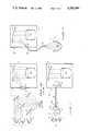
- FIG. 2is a schematic showing of a first embodiment of the solar simulator of this invention
- FIG. 3is a schematic showing of a second embodiment of the solar simulator of this invention.
- FIG. 4is a detailed schematic showing of a light source of FIG. 2 relative to the position of a fiber optic guide.
- FIG. 5is a detailed schematic showing of a second embodiment of the relative placement of a light source and a fiber optic guide
- FIG. 6is a detailed schematic showing of a third embodiment of the relative placement of a light source and a fiber optic guide
- FIG. 7is a detailed schematic showing of a fourth embodiment of the relative placement of a light source and a fiber optic guide
- FIG. 8is a detailed schematic showing of a fifth embodiment of the relative placement of a light source and a fiber optic guide.
- FIG. 9is a detailed schematic showing of a single light source and the relative placement of a plurality of fiber optic guides.
- FIG. 2depicts a schematic showing of the solar simulator 28 of this invention.
- three light sourcesare shown. It should be understood that the intensity level of these light sources is considerably less than the intensity of the light sources of those in FIG. 1.
- the parabolic light collectors 14direct substantially all of their light energy into the end 30 of its adjacent flexible optic guide 32 in the form of a large fiber optic.
- the fiber optic guideswould be fabricated from fused silica cores with silica cladding, which results in a numerical aperture of about 0.2, corresponding to a solid cone with a half angle of about 20 degrees.
- the ends 33 of the optic fiber guidesare joined at a junction 34 in a manner so that the light energy from each optic fiber guide 32 is combined when entering into fiber optic guide 36 (connections of this type are well known in the fiber optic art).
- the light guides 32may be contiguous through their entire length up to exit aperture 38. These guides are then placed in close proximity at point 34 to minimize the number of ports required in the chamber.
- Fiber optic guide 36passes through wall of the vacuum chamber 22 and has a pressure tight seal therewith.
- the distal end 38 of the fiber optic guide 36is positioned adjacent to the output collimator 24. If the output collimator is not required then the distal end 38 of fiber optic guide 36 is positioned directly over the test specimen 26 in a manner to cover the specimen with the desired amount of illumination.
- the solar simulator of the present inventioneliminates the requirement for the mirrors, field lens and integrator lens.
- FIG. 3depicts a solar simulator similar to the showing of FIG. 2 the only difference being that a larger intensity light source is employed which replaces the three light sources of FIG. 2.
- the end 33 of fiber optic guider 32extends into the chamber 22 in the same manner as fiber optic guide 36 described above.
- FIG. 4depicts a detailed schematic showing of a typical light source 12 and the parabolic housing 14.
- FIG. 5depicts a detailed schematic showing a light source inserted in series with a flexible optic guide.
- the fiber optic guideterminates in the same manner as described above to provide the light source at either end 33.
- FIG. 6depicts a detailed schematic showing of a light source embedded in a confined optic liquid medium 40 such as but, not limited to, silicone fluid.
- a confined optic liquid medium 40such as but, not limited to, silicone fluid.
- the liquid medium which serves to act as the core of a flexible light guideis confined by any suitable tubular housing material 42 suitable for practicing the invention as intended.
- the housingshould be clad with a layer having an index of refraction that is ideally less than that of the core fluid.
- FIG. 7is a showing similar to the showing of FIG. 6 with the light source embedded in a solid optic core such as a larger optic fiber.
- FIGS. 8 and 9are a schematic showing of multiple fiber optic guides connected to a single light source as shown in FIGS. 5 and 7 respectively.
Landscapes
- Physics & Mathematics (AREA)
- General Physics & Mathematics (AREA)
- Optics & Photonics (AREA)
- Life Sciences & Earth Sciences (AREA)
- Sustainable Development (AREA)
- Engineering & Computer Science (AREA)
- General Engineering & Computer Science (AREA)
- Photovoltaic Devices (AREA)
Abstract
Description
Claims (15)
Priority Applications (1)
| Application Number | Priority Date | Filing Date | Title |
|---|---|---|---|
| US07/101,533US4789989A (en) | 1987-09-25 | 1987-09-25 | Solar simulator employing flexible-optics |
Applications Claiming Priority (1)
| Application Number | Priority Date | Filing Date | Title |
|---|---|---|---|
| US07/101,533US4789989A (en) | 1987-09-25 | 1987-09-25 | Solar simulator employing flexible-optics |
Publications (1)
| Publication Number | Publication Date |
|---|---|
| US4789989Atrue US4789989A (en) | 1988-12-06 |
Family
ID=22285144
Family Applications (1)
| Application Number | Title | Priority Date | Filing Date |
|---|---|---|---|
| US07/101,533Expired - Fee RelatedUS4789989A (en) | 1987-09-25 | 1987-09-25 | Solar simulator employing flexible-optics |
Country Status (1)
| Country | Link |
|---|---|
| US (1) | US4789989A (en) |
Cited By (29)
| Publication number | Priority date | Publication date | Assignee | Title |
|---|---|---|---|---|
| US5021928A (en)* | 1982-09-29 | 1991-06-04 | Maurice Daniel | Flat panel illumination system |
| US5217285A (en)* | 1991-03-15 | 1993-06-08 | The United States Of America As Represented By United States Department Of Energy | Apparatus for synthesis of a solar spectrum |
| US5226107A (en)* | 1992-06-22 | 1993-07-06 | General Dynamics Corporation, Space Systems Division | Apparatus and method of using fiber-optic light guide for heating enclosed test articles |
| US5230555A (en)* | 1991-08-30 | 1993-07-27 | Progressive Dynamics, Inc. | Fiber optic arc lamp system |
| US5243500A (en)* | 1991-08-30 | 1993-09-07 | Progressive Dynamics, Inc. | Fiber optic arc lamp system |
| US5426569A (en)* | 1994-03-07 | 1995-06-20 | Midwest Research Institute | Method and apparatus for simulating atomospheric absorption of solar energy due to water vapor and CO2 |
| EP0658722A1 (en)* | 1993-11-29 | 1995-06-21 | Hughes Aircraft Company | Light cube module |
| US5544186A (en)* | 1994-01-25 | 1996-08-06 | Carl-Zeiss-Stiftung | Gas laser for emitting light modulated at two different wavelengths and an arrangement incorporating the gas laser to detect a gaseous substance |
| US5623149A (en)* | 1995-02-14 | 1997-04-22 | The Aerospace Corporation | High fidelity dual source solar simulator |
| US5642375A (en)* | 1995-10-26 | 1997-06-24 | Hewlett-Packard Company | Passively-locked external optical cavity |
| US5856665A (en)* | 1991-07-12 | 1999-01-05 | Jeffrey H. Price | Arc lamp stabilization and intensity control for imaging microscopy |
| US6030108A (en)* | 1992-08-07 | 2000-02-29 | Bridgestone Corporation | Waterproof lighting apparatus |
| WO2000013000A1 (en)* | 1998-09-01 | 2000-03-09 | Leo Baumann | Method and device for simulating the solar ultraviolet radiation load on materials |
| US20090279277A1 (en)* | 2008-05-09 | 2009-11-12 | Jungwirth Douglas R | Optical source assembly suitable for use as a solar simulator and associated methods |
| WO2010109037A1 (en) | 2009-03-27 | 2010-09-30 | Abengoa Solar New Technologies, S.A. | Variable-spectrum solar simulator |
| US20100271799A1 (en)* | 2008-05-09 | 2010-10-28 | The Boeing Company | Optical Source Assembly Suitable for Use as a Solar Simulator and Associated Methods |
| US8439530B2 (en) | 2011-02-16 | 2013-05-14 | The Boeing Company | Method and apparatus for simulating solar light |
| US8960930B2 (en) | 2010-09-27 | 2015-02-24 | Industrial Technology Research Institute | Solar simulator |
| EP2790469A3 (en)* | 2013-04-10 | 2015-08-19 | The Boeing Company | Multi-lamp solar simulator |
| US20160376037A1 (en) | 2014-05-14 | 2016-12-29 | California Institute Of Technology | Large-Scale Space-Based Solar Power Station: Packaging, Deployment and Stabilization of Lightweight Structures |
| CN109538992A (en)* | 2017-09-19 | 2019-03-29 | 光焱科技股份有限公司 | Solar simulator |
| US10454565B2 (en) | 2015-08-10 | 2019-10-22 | California Institute Of Technology | Systems and methods for performing shape estimation using sun sensors in large-scale space-based solar power stations |
| US10696428B2 (en) | 2015-07-22 | 2020-06-30 | California Institute Of Technology | Large-area structures for compact packaging |
| US10992253B2 (en) | 2015-08-10 | 2021-04-27 | California Institute Of Technology | Compactable power generation arrays |
| US11128179B2 (en) | 2014-05-14 | 2021-09-21 | California Institute Of Technology | Large-scale space-based solar power station: power transmission using steerable beams |
| US11362228B2 (en) | 2014-06-02 | 2022-06-14 | California Institute Of Technology | Large-scale space-based solar power station: efficient power generation tiles |
| US11634240B2 (en) | 2018-07-17 | 2023-04-25 | California Institute Of Technology | Coilable thin-walled longerons and coilable structures implementing longerons and methods for their manufacture and coiling |
| US11772826B2 (en) | 2018-10-31 | 2023-10-03 | California Institute Of Technology | Actively controlled spacecraft deployment mechanism |
| US12021162B2 (en) | 2014-06-02 | 2024-06-25 | California Institute Of Technology | Ultralight photovoltaic power generation tiles |
Citations (6)
| Publication number | Priority date | Publication date | Assignee | Title |
|---|---|---|---|---|
| US3772506A (en)* | 1971-07-07 | 1973-11-13 | Original Hanau Quarzlampen | Operating lamp provided with a light pipe |
| US4011403A (en)* | 1976-03-30 | 1977-03-08 | Northwestern University | Fiber optic laser illuminators |
| US4389115A (en)* | 1981-08-06 | 1983-06-21 | Richter Thomas A | Optical system |
| US4460939A (en)* | 1980-10-17 | 1984-07-17 | Fuji Photo Optical Co., Ltd. | Device for producing a line of illumination |
| US4556284A (en)* | 1980-12-19 | 1985-12-03 | Siemens Aktiengesellschaft | Apparatus for combining an optical and laser system and including a self-focussing optical fiber bundle |
| US4681396A (en)* | 1984-10-09 | 1987-07-21 | General Electric Company | High power laser energy delivery system |
- 1987
- 1987-09-25USUS07/101,533patent/US4789989A/ennot_activeExpired - Fee Related
Patent Citations (6)
| Publication number | Priority date | Publication date | Assignee | Title |
|---|---|---|---|---|
| US3772506A (en)* | 1971-07-07 | 1973-11-13 | Original Hanau Quarzlampen | Operating lamp provided with a light pipe |
| US4011403A (en)* | 1976-03-30 | 1977-03-08 | Northwestern University | Fiber optic laser illuminators |
| US4460939A (en)* | 1980-10-17 | 1984-07-17 | Fuji Photo Optical Co., Ltd. | Device for producing a line of illumination |
| US4556284A (en)* | 1980-12-19 | 1985-12-03 | Siemens Aktiengesellschaft | Apparatus for combining an optical and laser system and including a self-focussing optical fiber bundle |
| US4389115A (en)* | 1981-08-06 | 1983-06-21 | Richter Thomas A | Optical system |
| US4681396A (en)* | 1984-10-09 | 1987-07-21 | General Electric Company | High power laser energy delivery system |
Cited By (37)
| Publication number | Priority date | Publication date | Assignee | Title |
|---|---|---|---|---|
| US5021928A (en)* | 1982-09-29 | 1991-06-04 | Maurice Daniel | Flat panel illumination system |
| US5217285A (en)* | 1991-03-15 | 1993-06-08 | The United States Of America As Represented By United States Department Of Energy | Apparatus for synthesis of a solar spectrum |
| US5856665A (en)* | 1991-07-12 | 1999-01-05 | Jeffrey H. Price | Arc lamp stabilization and intensity control for imaging microscopy |
| US5230555A (en)* | 1991-08-30 | 1993-07-27 | Progressive Dynamics, Inc. | Fiber optic arc lamp system |
| US5243500A (en)* | 1991-08-30 | 1993-09-07 | Progressive Dynamics, Inc. | Fiber optic arc lamp system |
| US5283718A (en)* | 1991-08-30 | 1994-02-01 | Progressive Dynamics, Inc. | Fiber optic arc lamp system |
| US5226107A (en)* | 1992-06-22 | 1993-07-06 | General Dynamics Corporation, Space Systems Division | Apparatus and method of using fiber-optic light guide for heating enclosed test articles |
| US6030108A (en)* | 1992-08-07 | 2000-02-29 | Bridgestone Corporation | Waterproof lighting apparatus |
| US5676446A (en)* | 1993-11-29 | 1997-10-14 | Hughes Aircraft Company | Light cube module |
| EP0658722A1 (en)* | 1993-11-29 | 1995-06-21 | Hughes Aircraft Company | Light cube module |
| US5544186A (en)* | 1994-01-25 | 1996-08-06 | Carl-Zeiss-Stiftung | Gas laser for emitting light modulated at two different wavelengths and an arrangement incorporating the gas laser to detect a gaseous substance |
| US5426569A (en)* | 1994-03-07 | 1995-06-20 | Midwest Research Institute | Method and apparatus for simulating atomospheric absorption of solar energy due to water vapor and CO2 |
| US5623149A (en)* | 1995-02-14 | 1997-04-22 | The Aerospace Corporation | High fidelity dual source solar simulator |
| US5642375A (en)* | 1995-10-26 | 1997-06-24 | Hewlett-Packard Company | Passively-locked external optical cavity |
| WO2000013000A1 (en)* | 1998-09-01 | 2000-03-09 | Leo Baumann | Method and device for simulating the solar ultraviolet radiation load on materials |
| US20090279277A1 (en)* | 2008-05-09 | 2009-11-12 | Jungwirth Douglas R | Optical source assembly suitable for use as a solar simulator and associated methods |
| US20100271799A1 (en)* | 2008-05-09 | 2010-10-28 | The Boeing Company | Optical Source Assembly Suitable for Use as a Solar Simulator and Associated Methods |
| US9063006B2 (en) | 2008-05-09 | 2015-06-23 | The Boeing Company | Optical source assembly suitable for use as a solar simulator and associated methods |
| WO2010109037A1 (en) | 2009-03-27 | 2010-09-30 | Abengoa Solar New Technologies, S.A. | Variable-spectrum solar simulator |
| US8579446B2 (en) | 2009-03-27 | 2013-11-12 | Abengoa Solar Technologies, S.A. | Variable-spectrum solar simulator |
| US8960930B2 (en) | 2010-09-27 | 2015-02-24 | Industrial Technology Research Institute | Solar simulator |
| US8439530B2 (en) | 2011-02-16 | 2013-05-14 | The Boeing Company | Method and apparatus for simulating solar light |
| US9410669B2 (en) | 2013-04-10 | 2016-08-09 | The Boeing Company | Multi-lamp solar simulator |
| EP2790469A3 (en)* | 2013-04-10 | 2015-08-19 | The Boeing Company | Multi-lamp solar simulator |
| US11128179B2 (en) | 2014-05-14 | 2021-09-21 | California Institute Of Technology | Large-scale space-based solar power station: power transmission using steerable beams |
| US20160376037A1 (en) | 2014-05-14 | 2016-12-29 | California Institute Of Technology | Large-Scale Space-Based Solar Power Station: Packaging, Deployment and Stabilization of Lightweight Structures |
| US10144533B2 (en) | 2014-05-14 | 2018-12-04 | California Institute Of Technology | Large-scale space-based solar power station: multi-scale modular space power |
| US10340698B2 (en) | 2014-05-14 | 2019-07-02 | California Institute Of Technology | Large-scale space-based solar power station: packaging, deployment and stabilization of lightweight structures |
| US12021162B2 (en) | 2014-06-02 | 2024-06-25 | California Institute Of Technology | Ultralight photovoltaic power generation tiles |
| US11362228B2 (en) | 2014-06-02 | 2022-06-14 | California Institute Of Technology | Large-scale space-based solar power station: efficient power generation tiles |
| US10696428B2 (en) | 2015-07-22 | 2020-06-30 | California Institute Of Technology | Large-area structures for compact packaging |
| US10454565B2 (en) | 2015-08-10 | 2019-10-22 | California Institute Of Technology | Systems and methods for performing shape estimation using sun sensors in large-scale space-based solar power stations |
| US10992253B2 (en) | 2015-08-10 | 2021-04-27 | California Institute Of Technology | Compactable power generation arrays |
| US10749593B2 (en) | 2015-08-10 | 2020-08-18 | California Institute Of Technology | Systems and methods for controlling supply voltages of stacked power amplifiers |
| CN109538992A (en)* | 2017-09-19 | 2019-03-29 | 光焱科技股份有限公司 | Solar simulator |
| US11634240B2 (en) | 2018-07-17 | 2023-04-25 | California Institute Of Technology | Coilable thin-walled longerons and coilable structures implementing longerons and methods for their manufacture and coiling |
| US11772826B2 (en) | 2018-10-31 | 2023-10-03 | California Institute Of Technology | Actively controlled spacecraft deployment mechanism |
Similar Documents
| Publication | Publication Date | Title |
|---|---|---|
| US4789989A (en) | Solar simulator employing flexible-optics | |
| US6538251B1 (en) | Radiation source assembly and transducer for analyzing gases or other substances | |
| Al-Azzawi et al. | Photonics: principles and practices | |
| US4776666A (en) | Projector for projecting fixed star | |
| JP2004527744A5 (en) | ||
| CN208537399U (en) | A kind of spectrometer being first divided | |
| KR880002738Y1 (en) | Artificial light source device | |
| US5584557A (en) | High efficiency compact illumination system | |
| CN105223137B (en) | A kind of optical measuring device for detection of biological samples | |
| WO1997001061A1 (en) | High efficiency compact illumination system | |
| CN109520944A (en) | A kind of universal spectroscopic analysis system | |
| CN111678066A (en) | Lighting system for simulating sunlight irradiation skylight | |
| US7149033B2 (en) | UV visual light beam combiner | |
| RU2380663C1 (en) | Solar radiation simulator | |
| CN207215699U (en) | A kind of universal spectroscopic analysis system | |
| JPH08240525A (en) | Multi purpose optical sensor | |
| CN101031782A (en) | Measuring head for planar measurement of a sample | |
| Schulz et al. | Variations in the spectrum of the Seyfert Galaxy AK 120 | |
| GB2281967A (en) | A steam wetness optical probe | |
| CN107965709A (en) | A kind of sunlight simulation system | |
| CN209745804U (en) | Multi-channel portable spectrum system based on time-sharing lighting | |
| Serkowski et al. | Fabry-Perot radial velocity spectrometer | |
| Ellis et al. | GNOSIS: an OH suppression unit for near-infrared spectrographs | |
| US5426569A (en) | Method and apparatus for simulating atomospheric absorption of solar energy due to water vapor and CO2 | |
| US4432641A (en) | Visual defect inspection of masks |
Legal Events
| Date | Code | Title | Description |
|---|---|---|---|
| AS | Assignment | Owner name:GENERAL DYNAMICS CORPORATION, SPACE SYSTEMS DIVISI Free format text:ASSIGNMENT OF ASSIGNORS INTEREST.;ASSIGNOR:STERN, THEODORE G.;REEL/FRAME:004820/0602 Effective date:19870914 Owner name:GENERAL DYNAMICS CORPORATION, SPACE SYSTEMS DIVISI Free format text:ASSIGNMENT OF ASSIGNORS INTEREST.;ASSIGNOR:NIRSCHL, DONALD A.;REEL/FRAME:004820/0601 Effective date:19870921 Owner name:GENERAL DYNAMICS CORPORATION, SPACE SYSTEMS DIVISI Free format text:ASSIGNMENT OF ASSIGNORS INTEREST.;ASSIGNOR:CORNWALL, MICKEY;REEL/FRAME:004820/0603 Effective date:19870914 | |
| FPAY | Fee payment | Year of fee payment:4 | |
| AS | Assignment | Owner name:MARTIN MARIETTA CORPORATION, MARYLAND Free format text:ASSIGNMENT OF ASSIGNORS INTEREST;ASSIGNOR:GENERAL DYNAMICS CORPORATION;REEL/FRAME:007197/0822 Effective date:19940819 | |
| REMI | Maintenance fee reminder mailed | ||
| LAPS | Lapse for failure to pay maintenance fees | ||
| FP | Lapsed due to failure to pay maintenance fee | Effective date:19961211 | |
| AS | Assignment | Owner name:LOCKHEED MARTIN CORPORATION, MARYLAND Free format text:MERGER;ASSIGNOR:MARTIN MARIETTA CORPORATION;REEL/FRAME:009414/0706 Effective date:19960125 | |
| STCH | Information on status: patent discontinuation | Free format text:PATENT EXPIRED DUE TO NONPAYMENT OF MAINTENANCE FEES UNDER 37 CFR 1.362 |