US4789480A - Membrane module and the use thereof for the separation of liquids according to the pervaporation process - Google Patents
Membrane module and the use thereof for the separation of liquids according to the pervaporation processDownload PDFInfo
- Publication number
- US4789480A US4789480AUS06/753,796US75379685AUS4789480AUS 4789480 AUS4789480 AUS 4789480AUS 75379685 AUS75379685 AUS 75379685AUS 4789480 AUS4789480 AUS 4789480A
- Authority
- US
- United States
- Prior art keywords
- membrane
- cavity
- conduit
- membrane element
- membranes
- Prior art date
- Legal status (The legal status is an assumption and is not a legal conclusion. Google has not performed a legal analysis and makes no representation as to the accuracy of the status listed.)
- Expired - Fee Related
Links
- 239000012528membraneSubstances0.000titleclaimsabstractdescription103
- 238000005373pervaporationMethods0.000titleclaimsdescription9
- 238000000034methodMethods0.000titleclaimsdescription7
- 238000000926separation methodMethods0.000titledescription12
- 239000007788liquidSubstances0.000titledescription9
- 238000004891communicationMethods0.000claimsabstractdescription7
- 239000012466permeateSubstances0.000claimsdescription19
- 239000000203mixtureSubstances0.000claimsdescription15
- 239000000126substanceSubstances0.000claimsdescription9
- 239000003566sealing materialSubstances0.000claimsdescription4
- 125000006850spacer groupChemical group0.000claimsdescription2
- 239000000470constituentSubstances0.000claims3
- 239000004744fabricSubstances0.000description11
- 239000010410layerSubstances0.000description11
- 239000011261inert gasSubstances0.000description3
- 238000012856packingMethods0.000description2
- 238000007789sealingMethods0.000description2
- 239000000853adhesiveSubstances0.000description1
- 230000001070adhesive effectEffects0.000description1
- 239000002390adhesive tapeSubstances0.000description1
- 238000013459approachMethods0.000description1
- 238000007599dischargingMethods0.000description1
- 230000000694effectsEffects0.000description1
- 238000001704evaporationMethods0.000description1
- 230000008020evaporationEffects0.000description1
- 239000007789gasSubstances0.000description1
- 239000011229interlayerSubstances0.000description1
- 238000004519manufacturing processMethods0.000description1
- 239000000463materialSubstances0.000description1
- 229920000642polymerPolymers0.000description1
- 238000001223reverse osmosisMethods0.000description1
- 238000009958sewingMethods0.000description1
- 229920002379silicone rubberPolymers0.000description1
- 239000004945silicone rubberSubstances0.000description1
- XLYOFNOQVPJJNP-UHFFFAOYSA-NwaterSubstancesOXLYOFNOQVPJJNP-UHFFFAOYSA-N0.000description1
Images

Classifications
- B—PERFORMING OPERATIONS; TRANSPORTING
- B01—PHYSICAL OR CHEMICAL PROCESSES OR APPARATUS IN GENERAL
- B01D—SEPARATION
- B01D61/00—Processes of separation using semi-permeable membranes, e.g. dialysis, osmosis or ultrafiltration; Apparatus, accessories or auxiliary operations specially adapted therefor
- B01D61/36—Pervaporation; Membrane distillation; Liquid permeation
- B01D61/362—Pervaporation
- B—PERFORMING OPERATIONS; TRANSPORTING
- B01—PHYSICAL OR CHEMICAL PROCESSES OR APPARATUS IN GENERAL
- B01D—SEPARATION
- B01D63/00—Apparatus in general for separation processes using semi-permeable membranes
- B01D63/10—Spiral-wound membrane modules
- B01D63/103—Details relating to membrane envelopes
- B01D63/1031—Glue line or sealing patterns
- B—PERFORMING OPERATIONS; TRANSPORTING
- B01—PHYSICAL OR CHEMICAL PROCESSES OR APPARATUS IN GENERAL
- B01D—SEPARATION
- B01D2313/00—Details relating to membrane modules or apparatus
- B01D2313/04—Specific sealing means
- B01D2313/042—Adhesives or glues
Definitions
- the present inventionis concerned with a membrane module, especially for performing separation of liquid mixtures according to the process of liquid permeation or pervaporation.
- the state-of-art systems for the separation of substance mixtureshave incorporated spiral-wound modules.
- Membranes suitable for use in the manufacture of such modulesare arranged so that the inactive membrane faces are superposed, i.e. with the active faces thereof arranged outwardly, and are cemented together at the edges. Inserted into the resulting pockets are fleeces or cloths for draining the permeate.
- One or several of the pocketsare secured to tubes provided with bores in the area of the cylindrical surface such that draining of the permeate can take place through the bores into the interior of the tube, there being no possibility of an outflow from the tube interior onto the active external surface (separating layer) of the membranes.
- the one or several membrane pockets, the draining discharge of which is in communication with the tube interior,are spirally wound about the tube, with interlayers of plastic fabric between the active membrane faces keeping open a liquid channel, and are sealed.
- the so obtained membrane modules thus obtainedhave two liquid channels separated by the membrane:
- the inventionis thus concerned with a membrane module for the separation of substance mixtures, including a pocket-shaped membrane element comprising two oppositely disposed membranes containing separating layers optionally held in spaced relationship by means of an insert, with a supply/discharge conduit in communication with the interior of said pocket being provided on one end and with the membrane element being accommodated in a housing having supply and discharge lines, which is characterized in that the separating layers of the membranes are facing one another and that the membrane element also on the other end has a supply/discharge conduit in communication with the interior of the pocket.
- two flat membranes suitable for separation mixtures by means of pervaporationare so superposed that the separating layers (active layers) of the membranes are facing one another.
- the pockets-shaped membrane elementis formed so that thin strips of a sealing material, e.g. silicone rubber or another polymer that is also to have a special adhesive power, are interposed between the membranes along the longitudinal sides.
- the two membranes in a known mannerare then stitched through the inserted sealing strip, with one seam or a plurality of parallel seams being provided.
- a sealing materialcan be applied in a known manner to the seams on the fleece or cloth side of the membrane, or an adhesive tape can be applied to the edges also covering the seams on the fleece or cloth side.
- a pocketwill be formed, stitched and sealed along the longitudinal sides, comprising two membranes facing one another with the active separating layer, between which a channel that is permeable to liquids is created.
- the open narrow sides of the pocketare now cemented in a known manner to two supply/discharge conduits, preferably tubes, preferably having bores on the area of their cylindrical surface such that there is only one connection through the bores between the interior of the tubes and the interior of the pocket formed by the membranes.
- each tubeis sealed in liquid- and gas-tight manner by way of a suitable means.
- the mixture to be separatedis then supplied through a tube, and through the bore in the cylindrical face enters the liquid channel formed by the membranes, exiting through the bores in the cylindrical surface of the second tube and being discharged from the system through the second tube.
- the systemis an evacuated space or if an inert gas stream is guided over the open fleece or cloth side, permeating components can more easily pass through the membrane and evaporate at the open side thereof. This will deplete the mixture in the channel formed by the membranes of the more easily permeating components until the desired separation and re-concentration have been achieved.
- the arrangement comprised of the two tubes and the membranes therebetweenis spirally wound either about only one of the two tubes or in equal or different shares about both tubes either in the same direction or in counter-direction.
- a wide-meshed plastic fabric wound at the same timeprovides for keeping apart the fleece or cloth side of the membrane during operation and, hence, for keeping open the permeate channel.
- the spiral wound apparatusis held together and in shape by an outer envelope.
- a plurality of such devicescan be jointly accommodated in a suitable housing which is evacuated or through which an inert gas stream flows.
- the devicesare so aligned that the mixture to be separated will flow therethrough either in parallel or in succession; an optimum arrangement for the respective problem of separation can be computed by the one skilled in the art from the performance data of the membranes as used.
- the invention membrane module having open permeate channelsnot only is suitable for a separation of mixtures by means of pervaporation but also, when using corresponding membranes, for the advantageous separation of gas mixtures.
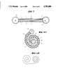
- FIG. 1is a schematic view of a membrane module according to the invention
- FIG. 2is a plan view of a membrane element partially broken away
- FIG. 3is a sectional view of FIG. 2, normal to line I,I', and
- FIGS. 4A and 4Bdepict, respectively, cross-sectional view of a spiral wound membrane module of the invention wherein the membrane is wound on one conduit (4A) and on both conduits (4B).
- the membrane module 1comprises a membrane element 2 in a housing 7 having supply and discharge conduits 8, 8', 8".
- FIG. 2shows a membrane element 2 with two membranes 4,4' and plastic fabric 3 therebetween, with separating layers 9,9' (see FIG. 3) facing one another, i.e. the separating layers are disposed inwardly.
- the two membranes 4,4'are cemented together along the longitudinal sides thereof and, in addition, are reinforced by seams 11,11'.
- the pocket-shaped structure comprised of membranes 4,4'is so cemented to tubes 6,6' having bores 10,10' that tubes 6,6' are in communication with the interior of the pocket. Intake is via one of the two tubes 6,6' and discharge in reconcentrated form is over the other of the two tubes 6,6', while the permeate passes through the membranes and is removed from housing 7 (FIG. 1).
- FIGS. 4A and 4Bshow in respective cross-section, a spirally wound membrane element 2, with a spacer 12 providing for the required distance between the membrane coils.
Landscapes
- Chemical & Material Sciences (AREA)
- Chemical Kinetics & Catalysis (AREA)
- Engineering & Computer Science (AREA)
- Water Supply & Treatment (AREA)
- Separation Using Semi-Permeable Membranes (AREA)
Abstract
Description
Claims (11)
Applications Claiming Priority (2)
| Application Number | Priority Date | Filing Date | Title |
|---|---|---|---|
| DE19823220613DE3220613A1 (en) | 1982-06-01 | 1982-06-01 | MEMBRANE MODULE AND ITS USE FOR SEPARATING LIQUIDS BY PERVAPORATION PROCESS |
| DE3220613 | 1982-06-01 |
Related Parent Applications (1)
| Application Number | Title | Priority Date | Filing Date |
|---|---|---|---|
| US06499846Continuation | 1983-06-01 |
Publications (1)
| Publication Number | Publication Date |
|---|---|
| US4789480Atrue US4789480A (en) | 1988-12-06 |
Family
ID=6165022
Family Applications (1)
| Application Number | Title | Priority Date | Filing Date |
|---|---|---|---|
| US06/753,796Expired - Fee RelatedUS4789480A (en) | 1982-06-01 | 1985-07-08 | Membrane module and the use thereof for the separation of liquids according to the pervaporation process |
Country Status (5)
| Country | Link |
|---|---|
| US (1) | US4789480A (en) |
| EP (1) | EP0096340B1 (en) |
| JP (1) | JPS59109206A (en) |
| AT (1) | ATE27231T1 (en) |
| DE (2) | DE3220613A1 (en) |
Cited By (18)
| Publication number | Priority date | Publication date | Assignee | Title |
|---|---|---|---|---|
| US5061297A (en)* | 1987-09-01 | 1991-10-29 | Alan Krasberg | Apparatus for and method of providing improved gas separation |
| US5069793A (en)* | 1990-09-12 | 1991-12-03 | Membrane Technology & Research, Inc. | Membrane module |
| US5098562A (en)* | 1991-01-04 | 1992-03-24 | Yoshihiko Shibata | Apparatus for treating deaerated water |
| US5258122A (en)* | 1992-04-16 | 1993-11-02 | Amicon, Inc. | Cross-flow filter device with pressure-balancing feature |
| US5266195A (en)* | 1992-08-10 | 1993-11-30 | Desalination Systems, Inc. | Spiral wound separation device and method of making same |
| US6039870A (en)* | 1998-05-05 | 2000-03-21 | Gollan; Arye Z. | Radial wound fiber disk |
| US6197191B1 (en)* | 1995-12-04 | 2001-03-06 | Aloys Wobben | Device for filtering and separating flow media |
| US6203707B1 (en)* | 1996-11-07 | 2001-03-20 | Bucher-Guyer Ag | Membrane module for a membrane separation system, its use and process for producing the same |
| WO2004112945A1 (en)* | 2003-06-25 | 2004-12-29 | Stichting Voor De Technische Wetenschappen | Spacer for use in a membrane separation device and a membrane separation device comprising such a spacer |
| KR100711834B1 (en) | 2006-06-23 | 2007-05-02 | 한국화학연구원 | Immersion membrane module |
| KR100809178B1 (en) | 2004-09-02 | 2008-02-29 | 닛토덴코 가부시키가이샤 | Spiral reverse osmosis membrane element, method of manufacturing the same, and its use method |
| KR100809177B1 (en) | 2003-10-02 | 2008-02-29 | 닛토덴코 가부시키가이샤 | Spiral membrane element and method of manufacturing the same |
| KR100826363B1 (en) | 2003-09-17 | 2008-05-02 | 닛토덴코 가부시키가이샤 | Spiral wound separation membrane element |
| KR100846647B1 (en) | 2005-10-31 | 2008-07-16 | 닛토덴코 가부시키가이샤 | Spiral separation membrane element |
| WO2018136077A1 (en) | 2017-01-20 | 2018-07-26 | Trevi Systems Inc. | Osmotic pressure assisted reverse osmosis membrane and module |
| US10478778B2 (en) | 2015-07-01 | 2019-11-19 | 3M Innovative Properties Company | Composite membranes with improved performance and/or durability and methods of use |
| US10618008B2 (en) | 2015-07-01 | 2020-04-14 | 3M Innovative Properties Company | Polymeric ionomer separation membranes and methods of use |
| US10737220B2 (en) | 2015-07-01 | 2020-08-11 | 3M Innovative Properties Company | PVP- and/or PVL-containing composite membranes and methods of use |
Families Citing this family (8)
| Publication number | Priority date | Publication date | Assignee | Title |
|---|---|---|---|---|
| US4855058A (en)* | 1986-06-24 | 1989-08-08 | Hydranautics | High recovery spiral wound membrane element |
| DE3670452D1 (en)* | 1986-07-22 | 1990-05-23 | Vogelbusch Gmbh | MEMBRANE BAG, WRAP MODULE FROM SUCH A MEMBRANE BAG, AND METHOD FOR THE PRODUCTION THEREOF. |
| HU207491B (en)* | 1987-10-13 | 1993-04-28 | Tatabanyai Banyak Vallalat | Device for separating the components of fluid solutions and gas mixtures and method for forming the device |
| DE3824839C1 (en)* | 1988-07-21 | 1989-10-05 | Erwin Sick Gmbh Optik-Elektronik, 7808 Waldkirch, De | |
| EP0448973B1 (en)* | 1990-02-27 | 1995-12-20 | Toray Industries, Inc. | Spiral wound gas permeable membrane module and apparatus and method for using the same |
| DE4244823C2 (en)* | 1992-09-01 | 1996-10-24 | Sep Tech Studien | Values and water recovery from aq. process liq. |
| DE4326677A1 (en)* | 1993-08-09 | 1995-02-16 | Gore W L & Ass Gmbh | Membrane module for removing gaseous substances from a gas stream |
| PT1319079E (en) | 2000-09-21 | 2012-12-21 | Basf Se | Talaromyces xylanase |
Citations (11)
| Publication number | Priority date | Publication date | Assignee | Title |
|---|---|---|---|---|
| US2958657A (en)* | 1954-07-16 | 1960-11-01 | American Oil Co | Method of separating hydrocarbons using ethyl cellulose permselective membrane |
| US3252272A (en)* | 1962-01-11 | 1966-05-24 | Kerr Mc Gee Oil Ind Inc | Apparatus for separating materials |
| GB1096680A (en)* | 1964-12-09 | 1967-12-29 | Pactide Corp | Distillation apparatus and method of distillation |
| US3367787A (en)* | 1963-01-25 | 1968-02-06 | Henricus Alexis Cornelis Thijs | Evaporation concentration of liquids |
| US3367504A (en)* | 1964-12-21 | 1968-02-06 | Gulf General Atomic Inc | Spirally wrapped reverse osmosis membrane cell |
| US3839201A (en)* | 1972-12-18 | 1974-10-01 | E Miller | Reverse osmosis separator unit |
| DE2634369A1 (en)* | 1975-08-01 | 1977-02-03 | Erika Inc | FUEL EXCHANGE DEVICE |
| US4083780A (en)* | 1976-07-29 | 1978-04-11 | Envirogenics Systems Company | Fluid purification system |
| US4147114A (en)* | 1977-11-04 | 1979-04-03 | Thiokol Corporation | Waste treatment system |
| GB2063705A (en)* | 1979-11-16 | 1981-06-10 | Envirogenics Syst | Spiral wrap reverse osmosis membrane element |
| EP0040411A1 (en)* | 1980-05-21 | 1981-11-25 | Hoechst Aktiengesellschaft | Apparatus for separating mixtures in the liquid phase |
Family Cites Families (3)
| Publication number | Priority date | Publication date | Assignee | Title |
|---|---|---|---|---|
| JPS5195986A (en)* | 1975-02-20 | 1976-08-23 | Ryutainobunrihoho oyobi sonosochi | |
| JPS5498851U (en)* | 1977-12-23 | 1979-07-12 | ||
| JPS54122679A (en)* | 1978-03-16 | 1979-09-22 | Nitto Electric Ind Co Ltd | Fluid permeating and separating unit |
- 1982
- 1982-06-01DEDE19823220613patent/DE3220613A1/ennot_activeWithdrawn
- 1983
- 1983-05-31ATAT83105380Tpatent/ATE27231T1/ennot_activeIP Right Cessation
- 1983-05-31DEDE8383105380Tpatent/DE3371596D1/ennot_activeExpired
- 1983-05-31EPEP83105380Apatent/EP0096340B1/ennot_activeExpired
- 1983-06-01JPJP58095887Apatent/JPS59109206A/enactiveGranted
- 1985
- 1985-07-08USUS06/753,796patent/US4789480A/ennot_activeExpired - Fee Related
Patent Citations (11)
| Publication number | Priority date | Publication date | Assignee | Title |
|---|---|---|---|---|
| US2958657A (en)* | 1954-07-16 | 1960-11-01 | American Oil Co | Method of separating hydrocarbons using ethyl cellulose permselective membrane |
| US3252272A (en)* | 1962-01-11 | 1966-05-24 | Kerr Mc Gee Oil Ind Inc | Apparatus for separating materials |
| US3367787A (en)* | 1963-01-25 | 1968-02-06 | Henricus Alexis Cornelis Thijs | Evaporation concentration of liquids |
| GB1096680A (en)* | 1964-12-09 | 1967-12-29 | Pactide Corp | Distillation apparatus and method of distillation |
| US3367504A (en)* | 1964-12-21 | 1968-02-06 | Gulf General Atomic Inc | Spirally wrapped reverse osmosis membrane cell |
| US3839201A (en)* | 1972-12-18 | 1974-10-01 | E Miller | Reverse osmosis separator unit |
| DE2634369A1 (en)* | 1975-08-01 | 1977-02-03 | Erika Inc | FUEL EXCHANGE DEVICE |
| US4083780A (en)* | 1976-07-29 | 1978-04-11 | Envirogenics Systems Company | Fluid purification system |
| US4147114A (en)* | 1977-11-04 | 1979-04-03 | Thiokol Corporation | Waste treatment system |
| GB2063705A (en)* | 1979-11-16 | 1981-06-10 | Envirogenics Syst | Spiral wrap reverse osmosis membrane element |
| EP0040411A1 (en)* | 1980-05-21 | 1981-11-25 | Hoechst Aktiengesellschaft | Apparatus for separating mixtures in the liquid phase |
Non-Patent Citations (2)
| Title |
|---|
| Kremen, Seymours, "Technology and Engineering of R06A-Spiral Wound Osmosis Membrane Modules", Chap. 17 of Reverse Osmosis and Synthetic Membranes, S. Sourirajan editor, National Res. Council Canada, 1977, pp. 371-385, NRCC. 15627. |
| Kremen, Seymours, Technology and Engineering of R06A Spiral Wound Osmosis Membrane Modules , Chap. 17 of Reverse Osmosis and Synthetic Membranes, S. Sourirajan editor, National Res. Council Canada, 1977, pp. 371 385, NRCC. 15627.* |
Cited By (20)
| Publication number | Priority date | Publication date | Assignee | Title |
|---|---|---|---|---|
| US5061297A (en)* | 1987-09-01 | 1991-10-29 | Alan Krasberg | Apparatus for and method of providing improved gas separation |
| US5069793A (en)* | 1990-09-12 | 1991-12-03 | Membrane Technology & Research, Inc. | Membrane module |
| US5098562A (en)* | 1991-01-04 | 1992-03-24 | Yoshihiko Shibata | Apparatus for treating deaerated water |
| US5258122A (en)* | 1992-04-16 | 1993-11-02 | Amicon, Inc. | Cross-flow filter device with pressure-balancing feature |
| US5266195A (en)* | 1992-08-10 | 1993-11-30 | Desalination Systems, Inc. | Spiral wound separation device and method of making same |
| US6197191B1 (en)* | 1995-12-04 | 2001-03-06 | Aloys Wobben | Device for filtering and separating flow media |
| US6203707B1 (en)* | 1996-11-07 | 2001-03-20 | Bucher-Guyer Ag | Membrane module for a membrane separation system, its use and process for producing the same |
| US6039870A (en)* | 1998-05-05 | 2000-03-21 | Gollan; Arye Z. | Radial wound fiber disk |
| WO2004112945A1 (en)* | 2003-06-25 | 2004-12-29 | Stichting Voor De Technische Wetenschappen | Spacer for use in a membrane separation device and a membrane separation device comprising such a spacer |
| KR100826363B1 (en) | 2003-09-17 | 2008-05-02 | 닛토덴코 가부시키가이샤 | Spiral wound separation membrane element |
| KR100809177B1 (en) | 2003-10-02 | 2008-02-29 | 닛토덴코 가부시키가이샤 | Spiral membrane element and method of manufacturing the same |
| KR100809178B1 (en) | 2004-09-02 | 2008-02-29 | 닛토덴코 가부시키가이샤 | Spiral reverse osmosis membrane element, method of manufacturing the same, and its use method |
| KR100846647B1 (en) | 2005-10-31 | 2008-07-16 | 닛토덴코 가부시키가이샤 | Spiral separation membrane element |
| KR100711834B1 (en) | 2006-06-23 | 2007-05-02 | 한국화학연구원 | Immersion membrane module |
| US10478778B2 (en) | 2015-07-01 | 2019-11-19 | 3M Innovative Properties Company | Composite membranes with improved performance and/or durability and methods of use |
| US10618008B2 (en) | 2015-07-01 | 2020-04-14 | 3M Innovative Properties Company | Polymeric ionomer separation membranes and methods of use |
| US10737220B2 (en) | 2015-07-01 | 2020-08-11 | 3M Innovative Properties Company | PVP- and/or PVL-containing composite membranes and methods of use |
| WO2018136077A1 (en) | 2017-01-20 | 2018-07-26 | Trevi Systems Inc. | Osmotic pressure assisted reverse osmosis membrane and module |
| EP3570965A4 (en)* | 2017-01-20 | 2021-02-17 | Trevi Systems Inc. | Osmotic pressure assisted reverse osmosis membrane and module |
| US11839853B2 (en) | 2017-01-20 | 2023-12-12 | Trevi Systems, Inc. | Osmotic pressure assisted reverse osmosis membrane and module |
Also Published As
| Publication number | Publication date |
|---|---|
| EP0096340A2 (en) | 1983-12-21 |
| EP0096340B1 (en) | 1987-05-20 |
| DE3220613A1 (en) | 1983-12-01 |
| JPS59109206A (en) | 1984-06-23 |
| ATE27231T1 (en) | 1987-06-15 |
| DE3371596D1 (en) | 1987-06-25 |
| JPH0558769B2 (en) | 1993-08-27 |
| EP0096340A3 (en) | 1984-03-21 |
Similar Documents
| Publication | Publication Date | Title |
|---|---|---|
| US4789480A (en) | Membrane module and the use thereof for the separation of liquids according to the pervaporation process | |
| US4613436A (en) | Membrane assembly for fluid separations-disk | |
| US3872014A (en) | Membrane separation apparatus | |
| US5158581A (en) | Fluid separation membrane module with hollow fibers having segregated active surface regions | |
| US3401798A (en) | Cylindrically stacked and spirally configured semi-permeable membrane laminate apparatus | |
| US5096584A (en) | Spiral-wound membrane separation device with feed and permeate/sweep fluid flow control | |
| US3774771A (en) | Reverse osmosis module | |
| US5458774A (en) | Corrugated spiral membrane module | |
| US3837146A (en) | Separating apparatus particularly suitable for gas permeation and in pervaporation | |
| GB1113630A (en) | Improved method and apparatus for use in the reverse osmotic separation of liquid solvents from liquid feed solutions | |
| KR950701544A (en) | Cassette membrand system and method of use for low pressure separations | |
| JPH06500498A (en) | membrane module | |
| JPH05212253A (en) | Hollow fiber bundle open at both ends and fluid separating device | |
| US4340475A (en) | Membrane separation cell | |
| CN103796743B (en) | Lipophilic pervaporation membrane modules | |
| EP0356177A1 (en) | Spiral module fluid treatment device | |
| US4761229A (en) | Multi-leaf membrane module | |
| US3173867A (en) | Membrane separation device | |
| EP0088459A2 (en) | Apparatus for mass transfer | |
| JPH0259016A (en) | gas separation membrane module | |
| USRE26097E (en) | Michaelsmembrane separation device | |
| JP3900624B2 (en) | Membrane separator | |
| JPH01288303A (en) | Fluid separation element | |
| CA1290258C (en) | Membrane assembly for fluid separations - disk | |
| JPS5944081B2 (en) | Complex selective separation membrane module |
Legal Events
| Date | Code | Title | Description |
|---|---|---|---|
| AS | Assignment | Owner name:GFT GESELLSCHAFT FUER TRENNTECHNIK MBH, A CORP. OF Free format text:ASSIGNMENT OF ASSIGNORS INTEREST.;ASSIGNOR:GFT INGENIEURBURO FUER INDUSTRIEANLAGENBAU;REEL/FRAME:005278/0624 Effective date:19891128 Owner name:GFT GESELLSCHAFT FUER TRENNTECHNIK MBH, A CORP. OF Free format text:ASSIGNMENT OF ASSIGNORS INTEREST.;ASSIGNOR:GFT INGENIEURBURO FUER INDUSTRIEANLAGENBAU;REEL/FRAME:005278/0628 Effective date:19891128 Owner name:GFT GESELLSCHAFT FUER TRENNTECHNIK MBH, A CORP. OF Free format text:ASSIGNMENT OF ASSIGNORS INTEREST.;ASSIGNOR:GFT INGENIEURBURO FUER INDUSTRIEANLAGENBAU;REEL/FRAME:005278/0616 Effective date:19891128 Owner name:GFT GESELLSCHAFT FUER TRENNTECHNIK MBH, A CORP. OF Free format text:ASSIGNMENT OF ASSIGNORS INTEREST.;ASSIGNOR:GFT INGENIEURBURO FUER INDUSTRIEANLAGENBAU;REEL/FRAME:005278/0620 Effective date:19891128 | |
| FEPP | Fee payment procedure | Free format text:PAYOR NUMBER ASSIGNED (ORIGINAL EVENT CODE: ASPN); ENTITY STATUS OF PATENT OWNER: LARGE ENTITY | |
| FPAY | Fee payment | Year of fee payment:4 | |
| FEPP | Fee payment procedure | Free format text:PAT HLDR NO LONGER CLAIMS SMALL ENT STAT AS INDIV INVENTOR (ORIGINAL EVENT CODE: LSM1); ENTITY STATUS OF PATENT OWNER: LARGE ENTITY | |
| FPAY | Fee payment | Year of fee payment:8 | |
| REMI | Maintenance fee reminder mailed | ||
| LAPS | Lapse for failure to pay maintenance fees | ||
| FP | Lapsed due to failure to pay maintenance fee | Effective date:20001206 | |
| STCH | Information on status: patent discontinuation | Free format text:PATENT EXPIRED DUE TO NONPAYMENT OF MAINTENANCE FEES UNDER 37 CFR 1.362 |