US4788967A - Endoscope - Google Patents
EndoscopeDownload PDFInfo
- Publication number
- US4788967A US4788967AUS06/927,082US92708286AUS4788967AUS 4788967 AUS4788967 AUS 4788967AUS 92708286 AUS92708286 AUS 92708286AUS 4788967 AUS4788967 AUS 4788967A
- Authority
- US
- United States
- Prior art keywords
- hole
- distal end
- bendable
- tube
- recess
- Prior art date
- Legal status (The legal status is an assumption and is not a legal conclusion. Google has not performed a legal analysis and makes no representation as to the accuracy of the status listed.)
- Expired - Lifetime
Links
Images


Classifications
- A—HUMAN NECESSITIES
- A61—MEDICAL OR VETERINARY SCIENCE; HYGIENE
- A61B—DIAGNOSIS; SURGERY; IDENTIFICATION
- A61B1/00—Instruments for performing medical examinations of the interior of cavities or tubes of the body by visual or photographical inspection, e.g. endoscopes; Illuminating arrangements therefor
- A61B1/012—Instruments for performing medical examinations of the interior of cavities or tubes of the body by visual or photographical inspection, e.g. endoscopes; Illuminating arrangements therefor characterised by internal passages or accessories therefor
- A—HUMAN NECESSITIES
- A61—MEDICAL OR VETERINARY SCIENCE; HYGIENE
- A61B—DIAGNOSIS; SURGERY; IDENTIFICATION
- A61B1/00—Instruments for performing medical examinations of the interior of cavities or tubes of the body by visual or photographical inspection, e.g. endoscopes; Illuminating arrangements therefor
- A61B1/00064—Constructional details of the endoscope body
- A61B1/00071—Insertion part of the endoscope body
- A61B1/0008—Insertion part of the endoscope body characterised by distal tip features
- A61B1/00089—Hoods
- A—HUMAN NECESSITIES
- A61—MEDICAL OR VETERINARY SCIENCE; HYGIENE
- A61B—DIAGNOSIS; SURGERY; IDENTIFICATION
- A61B1/00—Instruments for performing medical examinations of the interior of cavities or tubes of the body by visual or photographical inspection, e.g. endoscopes; Illuminating arrangements therefor
- A61B1/00064—Constructional details of the endoscope body
- A61B1/00071—Insertion part of the endoscope body
- A61B1/0008—Insertion part of the endoscope body characterised by distal tip features
- A61B1/00101—Insertion part of the endoscope body characterised by distal tip features the distal tip features being detachable
- A—HUMAN NECESSITIES
- A61—MEDICAL OR VETERINARY SCIENCE; HYGIENE
- A61B—DIAGNOSIS; SURGERY; IDENTIFICATION
- A61B1/00—Instruments for performing medical examinations of the interior of cavities or tubes of the body by visual or photographical inspection, e.g. endoscopes; Illuminating arrangements therefor
- A61B1/00163—Optical arrangements
- A61B1/00165—Optical arrangements with light-conductive means, e.g. fibre optics
- G—PHYSICS
- G02—OPTICS
- G02B—OPTICAL ELEMENTS, SYSTEMS OR APPARATUS
- G02B23/00—Telescopes, e.g. binoculars; Periscopes; Instruments for viewing the inside of hollow bodies; Viewfinders; Optical aiming or sighting devices
- G02B23/24—Instruments or systems for viewing the inside of hollow bodies, e.g. fibrescopes
- G02B23/26—Instruments or systems for viewing the inside of hollow bodies, e.g. fibrescopes using light guides
Definitions
- the present inventionrelates to an endoscope, and more specifically to an endoscope having an insertion section formed of a multi-lumen tube.
- the multi-lumen tubeincludes a solid tube member of flexible resin, having a plurality of insertion channels extending in its axial direction.
- the tube memberserves directly as the insertion section.
- An image guide fiber, light guide fiber, etc.,are inserted individually in the channels.
- an objective optical system and an illuminating optical systemare disposed in the distal end portion of the insertion section. Since the insertion section, formed of the multi-lumen tube, is flexible, its distal end portion can be deformed by the load of the optical systems therein. Accordingly, the optical systems may possibly become eccentric to the image guide fiber or light guide fiber, or their optical axes may incline at some angle to the central axis of the image or light guide fiber. In such cases, the optical systems cannot function well.
- the present inventionhas been contrived in consideration of these circumstances, and is intended to provide an endoscope, in which optical systems can fulfill their functions satisfactorily, and in which an insertion section can be prevented from being damaged when a laser beam is applied to the affected part of a patient's body.
- a rigid portionis attached to the distal end of an insertion section.
- the rigid portionhas at least one through hole, which communicates with one of the channels of the insertion section.
- An optical systemis disposed in the through hole, and the distal end of an image guide, passed through the channel, is inserted in the through hole and connected optically to the optical system.
- FIGS. 1 to 4show an endoscope according to a first embodiment of the present invention, in which FIG. 1 is a side view of the endoscope, FIG. 2 is a sectional view of the distal end portion of an insertion section, and FIGS. 3 and 4 are sectional views taken along lines III--III and IV--IV of FIG. 2, respectively; and
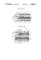
- FIGS. 5 to 8are sectional views of the distal end portions of insertion sections of endoscopes according to second to fifth embodiments of the invention, respectively.
- FIG. 1shows an outline of an endoscope according to the present invention.
- the endoscopecomprises operating section 10, insertion section 12, and universal cord 14. Section 12 and cord 14 both extend from section 10.
- insertion section 12is composed of flexible tube 16, made of synthetic resin, such as polyurethane resin or ethylene tetrafluoride resin.
- Tube 16has three insertion channels 18, 19 and 20 extending in its axial direction, and distal end face 16a. End face 16a is formed with recess 22, having a circular cross section, and channels 18, 19 and 20 open to the bottom surface of the recess.
- recess 22Fitted in recess 22 is cylindrical rigid member 24 which, made of stainless steel, has a diameter and length equivalent to those of the recess.
- Member 24is removably fixed to tube 16 by means of a bonding agent.
- Member 24has three through holes 26, 27 and 28 bored through it, in its axial direction.
- Rigid member 24is not limited to metal in material, and may alternatively be formed of ceramic material, such as alumina and zirconia, or be formed from carbon, or rigid plastic material, such as polysulfone resin, polycarbonate, denaturalized polyphenylene oxide, etc.
- Image guide fiber 32is passed through channel 18 of flexible tube 16.
- the distal end portion or incidence-side end portion of fiber 32is inserted in hole 26 of member 24, so as to be fixed to member 24 and connected optically to optical system 30.
- fiber 32is kept in alignment with the optical axis of system 30.
- the distal end portion of fiber 32has an end face 32a and is fixed to member 24 so that an optical image is imaged on the end face by optical system 30.
- the proximal end portion of fiber 32extends up to operating section 10.
- Light guide fiber 34is passed through channel 19.
- the distal end portion of fiber 34is inserted in hole 27 of rigid member 24, so as to be fixed to member 24 and connected optically to the illuminating system. Thus, fiber 34 is kept in alignment with the optical axis of the illuminating system.
- the proximal end portion of fiber 34extends through operating section 10 and universal cord 14.
- Channel 20 and hole 28define instrument channel 36, into which a forceps, laser probe, or some other medical instrument is to be inserted.
- rigid member 24is attached to the distal end of flexible tube 16, and objective optical system 30 and the illuminating optical system are arranged within member 24.
- the respective distal end portions of image guide fiber 32 and light guide fiber 34are fixed to rigid member 24 so that their optical axes are in alignment with their corresponding optical systems.
- the optical systemscannot become eccentric to guide fibers 32 and 34, that is, the optical axes of the optical systems cannot be deviated from those of the fibers.
- both the optical systemscan fulfill their functions satisfactorily.
- a laser probeis passed through instrument channel 36, to cauterize the affected part, with its distal end portion projected from the distal end of flexible tube 16.
- the distal end portion of tube 16is subjected to a laser beam reflected by the affected part.
- rigid member 24is fixed to the distal end of tube 16, so that the synthetic resin, constituting the tube, cannot receive the laser beam directly.
- the distal end of the flexible tube, or the distal end portion of insertion section 12can be prevented from being damaged by the beam.
- rigid member 24is removably fixed to flexible tube 16. Therefore, in repairing insertion section 12, if its image guide fiber is broken, for example, the rigid member, along with the optical systems, can be removed from the flexible tube. Thus, only a damaged portion or portions of the insertion section can be repaired or replaced, so that the optical systems can be reused.
- rigid member 24is bonded fixedly to flexible tube 16.
- itmay be fixed by press fit or ultrasonic welding.
- FIG. 5shows the distal end portion of an insertion section of an endoscope according to a second embodiment of the present invention.
- rigid member 24is in the form of a cylinder, having the same diameter as flexible tube 16, and is bonded fixedly to distal end face 16a of tube 16.
- Member 24has recess 38 in its end face on the flexible-tube side, besides through holes 26, 27 and 28.
- tube 16is formed with channel 40, communicating with recess 38, besides channel 18, 19 and 20.
- Operating wire 42 for bending insertion section 12is passed through channel 40.
- the distal end of wire 42is fixed to recess 38 of rigid member 24 by brazing or the like.
- the proximal end of wire 42is connected to operating knob 10a (FIG. 1), which is attached to operating section 10.
- the second embodimentis constructed in the same manner as the first embodiment, so that a description of those components is omitted herein.
- the second embodimentcan provide the same effects as the first embodiment.
- rigid member 24has cylindrical body 24a, which has substantially the same diameter as flexible tube 16, and is bonded fixedly to distal end face 16a of tube 16.
- Body 24ais formed with bores 43 and 44, extending in its axial direction.
- Member 24includes fixed cylinders 46 and 47, which are inserted fixedly in their corresponding bores of body 24a.
- One-side end portions of cylinders 46 and 47project from body 24a toward flexible tube 16, and are press-fitted into hollows 48 and 49, respectively, formed in end face 16a of tube 16.
- the inner peripheral surface of cylinder 46defines hole 26, which communicates with channel 18.
- the inner peripheral surface of cylinder 47defines hole 27, which communicates with channel 19.
- Objective optical system 30is disposed in hole 26.
- the distal end portion of image guide fiber 32is fixed in hole 26.
- no illuminating optical systemis used, and the distal end portion of light guide fiber 34 is inerted fully in hole 27, thus reaching the distal end of rigid member 24.
- the third embodimentprovides the following effect, besides the same effects of the first embodiments.
- body 24a of rigid member 24is bonded to distal end face 16a of flexible tube 16, and the respective end portions of fixed cylinders 46 and 47 are press-fitted individually into the distal end portion of tube 16.
- the strength of fixation of member 24 to tube 16is improved.
- FIG. 7shows a fourth embodiment of the present invention.
- This embodimentis constructed substantially in the same manner as the third embodiment, provided body 24a of rigid member 24 includes ring-shaped projection 50, which protrudes from the outer peripheral edge of body 24a, on the distal-end side of flexible tube 16, toward tube 16.
- Projection 50has fixing claw 50a which protrudes inward from the inner peripheral surface of its projecting end.
- the distal end portion of tube 16has a smaller diameter than any other portions thereof, thus constituting small-diameter portion 16b.
- Projection 50is fitted on portion 16b so that claw 50a bites into the outer peripheral surface of portion 16b.
- Cylindrical rigid member 24has ring-shaped projection 24b on its outer peripheral surface, and annular groove 22a is formed, correspondingly, on the wall surface of recess 22, in the distal end portion of flexible tube 16. Member 22 is bonded to recess 22 so that projection 24b is press-fitted into groove 22a of recess 22.
- the strength of fixation of rigid member 24 to flexible tube 16is greater than in the case of the first embodiment.
Landscapes
- Health & Medical Sciences (AREA)
- Life Sciences & Earth Sciences (AREA)
- Surgery (AREA)
- Physics & Mathematics (AREA)
- Optics & Photonics (AREA)
- Biomedical Technology (AREA)
- Animal Behavior & Ethology (AREA)
- Radiology & Medical Imaging (AREA)
- Nuclear Medicine, Radiotherapy & Molecular Imaging (AREA)
- Engineering & Computer Science (AREA)
- Biophysics (AREA)
- Heart & Thoracic Surgery (AREA)
- Medical Informatics (AREA)
- Molecular Biology (AREA)
- Pathology (AREA)
- General Health & Medical Sciences (AREA)
- Public Health (AREA)
- Veterinary Medicine (AREA)
- Astronomy & Astrophysics (AREA)
- General Physics & Mathematics (AREA)
- Endoscopes (AREA)
- Instruments For Viewing The Inside Of Hollow Bodies (AREA)
Abstract
Description
Claims (6)
Applications Claiming Priority (2)
| Application Number | Priority Date | Filing Date | Title |
|---|---|---|---|
| JP60254109AJPS62113125A (en) | 1985-11-13 | 1985-11-13 | Endoscope |
| JP60-254109 | 1985-11-13 |
Publications (1)
| Publication Number | Publication Date |
|---|---|
| US4788967Atrue US4788967A (en) | 1988-12-06 |
Family
ID=17260345
Family Applications (1)
| Application Number | Title | Priority Date | Filing Date |
|---|---|---|---|
| US06/927,082Expired - LifetimeUS4788967A (en) | 1985-11-13 | 1986-11-05 | Endoscope |
Country Status (3)
| Country | Link |
|---|---|
| US (1) | US4788967A (en) |
| JP (1) | JPS62113125A (en) |
| DE (1) | DE3637789A1 (en) |
Cited By (44)
| Publication number | Priority date | Publication date | Assignee | Title |
|---|---|---|---|---|
| US4871229A (en)* | 1987-11-11 | 1989-10-03 | Olympus Optical Co., Ltd. | Method for assembling optical fiber bundles in an endoscope |
| US5193525A (en)* | 1990-11-30 | 1993-03-16 | Vision Sciences | Antiglare tip in a sheath for an endoscope |
| US5275152A (en)* | 1992-07-27 | 1994-01-04 | Welch Allyn, Inc. | Insertion tube terminator |
| US5323766A (en)* | 1991-05-06 | 1994-06-28 | Endo Optiks Corporation | Illuminating endo-photocoagulation probe |
| US5351322A (en)* | 1992-08-18 | 1994-09-27 | Nirsystems Incorporated | Fiber optic probe |
| US5394499A (en)* | 1992-12-28 | 1995-02-28 | Olympus Optical Co., Ltd. | Observation system with an endoscope |
| US5842971A (en)* | 1996-05-22 | 1998-12-01 | Yoon; Inbae | Optical endoscopic portals and methods of using the same to establish passages through cavity walls |
| DE19826311A1 (en)* | 1998-06-12 | 1999-12-23 | Bauer Und Haeselbarth Chirurg | Laser resectoscope ensuring that part coming into contact with urinary tube during operation is neither turned nor displaced |
| US6038079A (en)* | 1997-10-09 | 2000-03-14 | Imagyn Medical Technologies, Inc. | Sapphire objective system |
| US6293910B1 (en)* | 1997-02-13 | 2001-09-25 | Matsushita Electric Industrial Co., Ltd. | Endoscope, method of manufacturing the same, and insertion member |
| US6468203B2 (en) | 2000-04-03 | 2002-10-22 | Neoguide Systems, Inc. | Steerable endoscope and improved method of insertion |
| US6610007B2 (en) | 2000-04-03 | 2003-08-26 | Neoguide Systems, Inc. | Steerable segmented endoscope and method of insertion |
| US20040015061A1 (en)* | 2002-07-16 | 2004-01-22 | Clifford Currier | Central venous catheter having a soft tip and fiber optics |
| US6800056B2 (en) | 2000-04-03 | 2004-10-05 | Neoguide Systems, Inc. | Endoscope with guiding apparatus |
| US6837846B2 (en) | 2000-04-03 | 2005-01-04 | Neo Guide Systems, Inc. | Endoscope having a guide tube |
| US6858005B2 (en) | 2000-04-03 | 2005-02-22 | Neo Guide Systems, Inc. | Tendon-driven endoscope and methods of insertion |
| US20050209618A1 (en)* | 2004-03-05 | 2005-09-22 | Auld Michael D | Rigid shafted instrumentation for vitreoretinal surgery |
| US6974411B2 (en) | 2000-04-03 | 2005-12-13 | Neoguide Systems, Inc. | Endoscope with single step guiding apparatus |
| US6984203B2 (en) | 2000-04-03 | 2006-01-10 | Neoguide Systems, Inc. | Endoscope with adjacently positioned guiding apparatus |
| US20060009740A1 (en)* | 2001-08-28 | 2006-01-12 | Michael Higgins | Multiple lumen catheter having a soft tip |
| US7029467B2 (en) | 2002-07-16 | 2006-04-18 | Edwards Lifesciences Corporation | Multiple lumen catheter having a soft tip |
| EP1723899A1 (en)* | 2005-05-20 | 2006-11-22 | Karl Storz Endovision, Inc. | Liner for endoscope working channel |
| US20070123752A1 (en)* | 2005-11-28 | 2007-05-31 | Karl Storz Endovision | Ceramic fiber optic taper housing for medical devices |
| US20090225159A1 (en)* | 2008-03-07 | 2009-09-10 | Scott Schneider | Visual inspection device |
| EP2344232A2 (en)* | 2008-10-08 | 2011-07-20 | Renishaw (Ireland) Limited | Rigid ceramic catheter |
| US8083879B2 (en) | 2005-11-23 | 2011-12-27 | Intuitive Surgical Operations, Inc. | Non-metallic, multi-strand control cable for steerable instruments |
| US8182418B2 (en) | 2008-02-25 | 2012-05-22 | Intuitive Surgical Operations, Inc. | Systems and methods for articulating an elongate body |
| US8361090B2 (en) | 2002-01-09 | 2013-01-29 | Intuitive Surgical Operations, Inc. | Apparatus and method for endoscopic colectomy |
| US8517923B2 (en) | 2000-04-03 | 2013-08-27 | Intuitive Surgical Operations, Inc. | Apparatus and methods for facilitating treatment of tissue via improved delivery of energy based and non-energy based modalities |
| US8568299B2 (en) | 2006-05-19 | 2013-10-29 | Intuitive Surgical Operations, Inc. | Methods and apparatus for displaying three-dimensional orientation of a steerable distal tip of an endoscope |
| US8834358B2 (en)* | 2009-03-27 | 2014-09-16 | EndoSphere Surgical, Inc. | Cannula with integrated camera and illumination |
| US8882657B2 (en) | 2003-03-07 | 2014-11-11 | Intuitive Surgical Operations, Inc. | Instrument having radio frequency identification systems and methods for use |
| US8888688B2 (en) | 2000-04-03 | 2014-11-18 | Intuitive Surgical Operations, Inc. | Connector device for a controllable instrument |
| US20150265142A1 (en)* | 2013-06-25 | 2015-09-24 | Olympus Medical Systems Corp. | Endoscope |
| US9220398B2 (en) | 2007-10-11 | 2015-12-29 | Intuitive Surgical Operations, Inc. | System for managing Bowden cables in articulating instruments |
| CN105491937A (en)* | 2013-09-03 | 2016-04-13 | 奥林匹斯冬季和Ibe有限公司 | Endoscope and endoscope tip |
| WO2016064449A1 (en) | 2014-10-20 | 2016-04-28 | Research Development International Corporation | Steerable micro-endoscope |
| US20180013937A1 (en)* | 2015-08-31 | 2018-01-11 | Panasonic Corporation | Endoscope |
| US10512392B2 (en) | 2008-02-06 | 2019-12-24 | Intuitive Surgical Operations, Inc. | Segmented instrument having braking capabilities |
| US10994076B1 (en) | 2019-07-25 | 2021-05-04 | Circulatech, Llc | Methods and devices to prevent obstructions in medical tubes |
| US11096563B2 (en) | 2005-11-22 | 2021-08-24 | Intuitive Surgical Operations, Inc. | Method of determining the shape of a bendable instrument |
| US11439429B2 (en) | 2019-07-11 | 2022-09-13 | New View Surgical | Cannula assembly with deployable camera |
| US20220386853A1 (en)* | 2020-03-04 | 2022-12-08 | Micro-Tech (Nanjing) Co., Ltd. | Imaging catheter and imaging device |
| CN115998422A (en)* | 2021-10-22 | 2023-04-25 | 捷锐士阿希迈公司(以奥林巴斯美国外科技术名义) | Embedded laser fiber for sucking type stone ablation |
Families Citing this family (5)
| Publication number | Priority date | Publication date | Assignee | Title |
|---|---|---|---|---|
| JPS649211U (en)* | 1987-07-06 | 1989-01-18 | ||
| JPH0255904U (en)* | 1988-10-18 | 1990-04-23 | ||
| FR2651986A1 (en)* | 1989-09-20 | 1991-03-22 | Croisy Renaud | CATHETER FOR VISION IN A CONDUIT, ESPECIALLY A HUMAN BODY. |
| US5421323A (en)* | 1992-12-02 | 1995-06-06 | Richard Wolf Gmbh | Endoscope with additional viewing aperture |
| DE19524444C2 (en)* | 1995-07-05 | 2001-02-15 | Dieter Bohn | Turbine blade measuring device |
Citations (6)
| Publication number | Priority date | Publication date | Assignee | Title |
|---|---|---|---|---|
| JPS53111591A (en)* | 1977-03-09 | 1978-09-29 | Sumitomo Metal Ind Ltd | Device for cutting end automatically off pipe |
| US4350150A (en)* | 1979-09-25 | 1982-09-21 | Olympus Optical Co., Ltd. | Structure of a light-receiving end portion of an endoscope light guide |
| US4367729A (en)* | 1979-10-22 | 1983-01-11 | Olympus Optical Co. Ltd. | Endoscope provided with an elongate medical treating instrument utilizing laser beams |
| US4419987A (en)* | 1979-12-21 | 1983-12-13 | Olympus Optical Co., Ltd. | Laser endoscope |
| JPS60249114A (en)* | 1984-05-04 | 1985-12-09 | ワーナー‐ランバート テクノロジーズ インク | Molded plastic head for fiber scope and manufacture thereof |
| US4576145A (en)* | 1983-02-22 | 1986-03-18 | Sumitomo Electric Industries, Ltd. | Fiberscope |
Family Cites Families (2)
| Publication number | Priority date | Publication date | Assignee | Title |
|---|---|---|---|---|
| JPS5584141A (en)* | 1978-12-19 | 1980-06-25 | Olympus Optical Co | Endoscope |
| JPS59111733A (en)* | 1982-12-17 | 1984-06-28 | オリンパス光学工業株式会社 | Endoscope |
- 1985
- 1985-11-13JPJP60254109Apatent/JPS62113125A/enactivePending
- 1986
- 1986-11-05USUS06/927,082patent/US4788967A/ennot_activeExpired - Lifetime
- 1986-11-06DEDE19863637789patent/DE3637789A1/enactiveGranted
Patent Citations (6)
| Publication number | Priority date | Publication date | Assignee | Title |
|---|---|---|---|---|
| JPS53111591A (en)* | 1977-03-09 | 1978-09-29 | Sumitomo Metal Ind Ltd | Device for cutting end automatically off pipe |
| US4350150A (en)* | 1979-09-25 | 1982-09-21 | Olympus Optical Co., Ltd. | Structure of a light-receiving end portion of an endoscope light guide |
| US4367729A (en)* | 1979-10-22 | 1983-01-11 | Olympus Optical Co. Ltd. | Endoscope provided with an elongate medical treating instrument utilizing laser beams |
| US4419987A (en)* | 1979-12-21 | 1983-12-13 | Olympus Optical Co., Ltd. | Laser endoscope |
| US4576145A (en)* | 1983-02-22 | 1986-03-18 | Sumitomo Electric Industries, Ltd. | Fiberscope |
| JPS60249114A (en)* | 1984-05-04 | 1985-12-09 | ワーナー‐ランバート テクノロジーズ インク | Molded plastic head for fiber scope and manufacture thereof |
Cited By (99)
| Publication number | Priority date | Publication date | Assignee | Title |
|---|---|---|---|---|
| US4871229A (en)* | 1987-11-11 | 1989-10-03 | Olympus Optical Co., Ltd. | Method for assembling optical fiber bundles in an endoscope |
| US5193525A (en)* | 1990-11-30 | 1993-03-16 | Vision Sciences | Antiglare tip in a sheath for an endoscope |
| US5323766A (en)* | 1991-05-06 | 1994-06-28 | Endo Optiks Corporation | Illuminating endo-photocoagulation probe |
| US5275152A (en)* | 1992-07-27 | 1994-01-04 | Welch Allyn, Inc. | Insertion tube terminator |
| US5351322A (en)* | 1992-08-18 | 1994-09-27 | Nirsystems Incorporated | Fiber optic probe |
| US5394499A (en)* | 1992-12-28 | 1995-02-28 | Olympus Optical Co., Ltd. | Observation system with an endoscope |
| US5842971A (en)* | 1996-05-22 | 1998-12-01 | Yoon; Inbae | Optical endoscopic portals and methods of using the same to establish passages through cavity walls |
| US6293910B1 (en)* | 1997-02-13 | 2001-09-25 | Matsushita Electric Industrial Co., Ltd. | Endoscope, method of manufacturing the same, and insertion member |
| US6038079A (en)* | 1997-10-09 | 2000-03-14 | Imagyn Medical Technologies, Inc. | Sapphire objective system |
| DE19826311C2 (en)* | 1998-06-12 | 2003-03-06 | Bauer Und Haeselbarth Chirurg | Laserresektoskop |
| DE19826311A1 (en)* | 1998-06-12 | 1999-12-23 | Bauer Und Haeselbarth Chirurg | Laser resectoscope ensuring that part coming into contact with urinary tube during operation is neither turned nor displaced |
| US6890297B2 (en) | 2000-04-03 | 2005-05-10 | Neo Guide Systems, Inc. | Steerable endoscope and improved method of insertion |
| US10736490B2 (en) | 2000-04-03 | 2020-08-11 | Intuitive Surgical Operations, Inc. | Connector device for a controllable instrument |
| US6610007B2 (en) | 2000-04-03 | 2003-08-26 | Neoguide Systems, Inc. | Steerable segmented endoscope and method of insertion |
| US20030191367A1 (en)* | 2000-04-03 | 2003-10-09 | Amir Belson | Steerable segmented endoscope and method of insertion |
| US12076102B2 (en) | 2000-04-03 | 2024-09-03 | Intuitive Surgical Operations, Inc. | Connector device for a controllable instrument |
| US6800056B2 (en) | 2000-04-03 | 2004-10-05 | Neoguide Systems, Inc. | Endoscope with guiding apparatus |
| US6837846B2 (en) | 2000-04-03 | 2005-01-04 | Neo Guide Systems, Inc. | Endoscope having a guide tube |
| US6858005B2 (en) | 2000-04-03 | 2005-02-22 | Neo Guide Systems, Inc. | Tendon-driven endoscope and methods of insertion |
| US6869396B2 (en) | 2000-04-03 | 2005-03-22 | Neoguide Systems, Inc. | Steerable endoscope and improved method of insertion |
| US8517923B2 (en) | 2000-04-03 | 2013-08-27 | Intuitive Surgical Operations, Inc. | Apparatus and methods for facilitating treatment of tissue via improved delivery of energy based and non-energy based modalities |
| US11026564B2 (en) | 2000-04-03 | 2021-06-08 | Intuitive Surgical Operations, Inc. | Apparatus and methods for facilitating treatment of tissue via improved delivery of energy based and non-energy based modalities |
| US6974411B2 (en) | 2000-04-03 | 2005-12-13 | Neoguide Systems, Inc. | Endoscope with single step guiding apparatus |
| US6984203B2 (en) | 2000-04-03 | 2006-01-10 | Neoguide Systems, Inc. | Endoscope with adjacently positioned guiding apparatus |
| US6468203B2 (en) | 2000-04-03 | 2002-10-22 | Neoguide Systems, Inc. | Steerable endoscope and improved method of insertion |
| US10893794B2 (en) | 2000-04-03 | 2021-01-19 | Intuitive Surgical Operations, Inc. | Steerable endoscope and improved method of insertion |
| US20020193661A1 (en)* | 2000-04-03 | 2002-12-19 | Amir Belson | Steerable endoscope and improved method of insertion |
| US7044907B2 (en) | 2000-04-03 | 2006-05-16 | Neoguide Systems, Inc. | Steerable endoscope and improved method of insertion |
| US7087013B2 (en) | 2000-04-03 | 2006-08-08 | Neoguide Systems, Inc. | Steerable segmented endoscope and method of insertion |
| US10327625B2 (en) | 2000-04-03 | 2019-06-25 | Intuitive Surgical Operations, Inc. | Apparatus and methods for facilitating treatment of tissue via improved delivery of energy based and non-energy based modalities |
| US10105036B2 (en) | 2000-04-03 | 2018-10-23 | Intuitive Surgical Operations, Inc. | Connector device for a controllable instrument |
| US9808140B2 (en) | 2000-04-03 | 2017-11-07 | Intuitive Surgical Operations, Inc. | Steerable segmented endoscope and method of insertion |
| US9427282B2 (en) | 2000-04-03 | 2016-08-30 | Intuitive Surgical Operations, Inc. | Apparatus and methods for facilitating treatment of tissue via improved delivery of energy based and non-energy based modalities |
| US9138132B2 (en) | 2000-04-03 | 2015-09-22 | Intuitive Surgical Operations, Inc. | Steerable endoscope and improved method of insertion |
| US8888688B2 (en) | 2000-04-03 | 2014-11-18 | Intuitive Surgical Operations, Inc. | Connector device for a controllable instrument |
| US8845524B2 (en) | 2000-04-03 | 2014-09-30 | Intuitive Surgical Operations, Inc. | Steerable segmented endoscope and method of insertion |
| US8834354B2 (en) | 2000-04-03 | 2014-09-16 | Intuitive Surgical Operations, Inc. | Steerable endoscope and improved method of insertion |
| US8062212B2 (en) | 2000-04-03 | 2011-11-22 | Intuitive Surgical Operations, Inc. | Steerable endoscope and improved method of insertion |
| US8827894B2 (en) | 2000-04-03 | 2014-09-09 | Intuitive Surgical Operations, Inc. | Steerable endoscope and improved method of insertion |
| US8721530B2 (en) | 2000-04-03 | 2014-05-13 | Intuitive Surgical Operations, Inc. | Tendon-driven endoscope and methods of use |
| US8641602B2 (en) | 2000-04-03 | 2014-02-04 | Intuitive Surgical Operations, Inc. | Steerable endoscope and improved method of insertion |
| US8226546B2 (en) | 2000-04-03 | 2012-07-24 | Intuitive Surgical Operations, Inc. | Steerable endoscope and improved method of insertion |
| US20060009740A1 (en)* | 2001-08-28 | 2006-01-12 | Michael Higgins | Multiple lumen catheter having a soft tip |
| US8361090B2 (en) | 2002-01-09 | 2013-01-29 | Intuitive Surgical Operations, Inc. | Apparatus and method for endoscopic colectomy |
| US9421016B2 (en) | 2002-01-09 | 2016-08-23 | Intuitive Surgical Operations, Inc. | Apparatus and method for endoscopic colectomy |
| US8696694B2 (en) | 2002-01-09 | 2014-04-15 | Intuitive Surgical Operations, Inc. | Apparatus and method for endoscopic colectomy |
| US10349816B2 (en) | 2002-01-09 | 2019-07-16 | Intuitive Surgical Operations, Inc. | Apparatus and method for endoscopic colectomy |
| US20040015061A1 (en)* | 2002-07-16 | 2004-01-22 | Clifford Currier | Central venous catheter having a soft tip and fiber optics |
| US6999809B2 (en) | 2002-07-16 | 2006-02-14 | Edwards Lifesciences Corporation | Central venous catheter having a soft tip and fiber optics |
| US7029467B2 (en) | 2002-07-16 | 2006-04-18 | Edwards Lifesciences Corporation | Multiple lumen catheter having a soft tip |
| US8882657B2 (en) | 2003-03-07 | 2014-11-11 | Intuitive Surgical Operations, Inc. | Instrument having radio frequency identification systems and methods for use |
| US10959807B2 (en) | 2003-03-07 | 2021-03-30 | Intuitive Surgical Operations, Inc. | Systems and methods for determining the state of motion of an instrument |
| US9980778B2 (en) | 2003-03-07 | 2018-05-29 | Intuitive Surgical Operations, Inc. | Instrument having radio frequency identification systems and methods for use |
| US20050209618A1 (en)* | 2004-03-05 | 2005-09-22 | Auld Michael D | Rigid shafted instrumentation for vitreoretinal surgery |
| US20060264708A1 (en)* | 2005-05-20 | 2006-11-23 | Karl Storz Endovision | Liner for endoscope working channel |
| EP1723899A1 (en)* | 2005-05-20 | 2006-11-22 | Karl Storz Endovision, Inc. | Liner for endoscope working channel |
| JP2006326306A (en)* | 2005-05-20 | 2006-12-07 | Karl Storz Endovision | Liner for endoscope working channel |
| US9439555B2 (en)* | 2005-05-20 | 2016-09-13 | Karl Storz Endovision, Inc. | Liner for endoscope working channel |
| US11096563B2 (en) | 2005-11-22 | 2021-08-24 | Intuitive Surgical Operations, Inc. | Method of determining the shape of a bendable instrument |
| US11617499B2 (en) | 2005-11-22 | 2023-04-04 | Intuitive Surgical Operations, Inc. | System for determining the shape of a bendable instrument |
| US8083879B2 (en) | 2005-11-23 | 2011-12-27 | Intuitive Surgical Operations, Inc. | Non-metallic, multi-strand control cable for steerable instruments |
| US7824330B2 (en) | 2005-11-28 | 2010-11-02 | Karl Storz Endovision, Inc. | Ceramic fiber optic taper housing for medical devices |
| US20070123752A1 (en)* | 2005-11-28 | 2007-05-31 | Karl Storz Endovision | Ceramic fiber optic taper housing for medical devices |
| US20100280323A1 (en)* | 2005-11-28 | 2010-11-04 | Melanson Jeffrey S | Ceramic Fiber Optic Taper Housing For Medical Devices |
| US8568299B2 (en) | 2006-05-19 | 2013-10-29 | Intuitive Surgical Operations, Inc. | Methods and apparatus for displaying three-dimensional orientation of a steerable distal tip of an endoscope |
| US9357901B2 (en) | 2006-05-19 | 2016-06-07 | Intuitive Surgical Operations, Inc. | Methods and apparatus for displaying three-dimensional orientation of a steerable distal tip of an endoscope |
| US10426412B2 (en) | 2006-05-19 | 2019-10-01 | Intuitive Surgical Operations, Inc. | Methods and apparatus for displaying three-dimensional orientation of a steerable distal tip of an endoscope |
| US12256891B2 (en) | 2006-05-19 | 2025-03-25 | Intuitive Surgical Operations, Inc. | Methods and apparatus for displaying three-dimensional orientation of a steerable distal tip of an endoscope |
| US9220398B2 (en) | 2007-10-11 | 2015-12-29 | Intuitive Surgical Operations, Inc. | System for managing Bowden cables in articulating instruments |
| US10512392B2 (en) | 2008-02-06 | 2019-12-24 | Intuitive Surgical Operations, Inc. | Segmented instrument having braking capabilities |
| US10952594B2 (en) | 2008-02-06 | 2021-03-23 | Intuitive Surgical Operations, Inc. | Segmented instrument having braking capabilities |
| US8182418B2 (en) | 2008-02-25 | 2012-05-22 | Intuitive Surgical Operations, Inc. | Systems and methods for articulating an elongate body |
| US8608647B2 (en) | 2008-02-25 | 2013-12-17 | Intuitive Surgical Operations, Inc. | Systems and methods for articulating an elongate body |
| US8988522B2 (en) | 2008-03-07 | 2015-03-24 | Milwaukee Electric Tool Corporation | Visual inspection device |
| US9986212B2 (en) | 2008-03-07 | 2018-05-29 | Milwaukee Electric Tool Corporation | Visual inspection device |
| US9693024B2 (en) | 2008-03-07 | 2017-06-27 | Milwaukee Electric Tool Corporation | Visual inspection device |
| US8659652B2 (en) | 2008-03-07 | 2014-02-25 | Milwaukee Electric Tool Corporation | Visual inspection device |
| US20090225159A1 (en)* | 2008-03-07 | 2009-09-10 | Scott Schneider | Visual inspection device |
| US8189043B2 (en) | 2008-03-07 | 2012-05-29 | Milwaukee Electric Tool Corporation | Hand-held visual inspection device for viewing confined or difficult to access locations |
| EP2344232A2 (en)* | 2008-10-08 | 2011-07-20 | Renishaw (Ireland) Limited | Rigid ceramic catheter |
| US8834358B2 (en)* | 2009-03-27 | 2014-09-16 | EndoSphere Surgical, Inc. | Cannula with integrated camera and illumination |
| US9636009B2 (en)* | 2013-06-25 | 2017-05-02 | Olympus Corporation | Endoscope |
| US20150265142A1 (en)* | 2013-06-25 | 2015-09-24 | Olympus Medical Systems Corp. | Endoscope |
| CN105491937A (en)* | 2013-09-03 | 2016-04-13 | 奥林匹斯冬季和Ibe有限公司 | Endoscope and endoscope tip |
| EP3735925A1 (en) | 2014-10-20 | 2020-11-11 | Research Development International Corporation | Steerable micro-endoscope having an electro-surgery tool and zip-catheter |
| US11540703B2 (en) | 2014-10-20 | 2023-01-03 | Research Development International Corporation | Steerable micro-endoscope |
| WO2016064449A1 (en) | 2014-10-20 | 2016-04-28 | Research Development International Corporation | Steerable micro-endoscope |
| US11103127B2 (en) | 2014-10-20 | 2021-08-31 | Research Development International Corporation | Steerable micro-endoscope |
| US20180013937A1 (en)* | 2015-08-31 | 2018-01-11 | Panasonic Corporation | Endoscope |
| US10560612B2 (en)* | 2015-08-31 | 2020-02-11 | Panasonic I-Pro Sensing Solutions Co., Ltd. | Endoscope |
| US10389921B2 (en) | 2015-08-31 | 2019-08-20 | Panasonic Corporation | Endoscope |
| US11439429B2 (en) | 2019-07-11 | 2022-09-13 | New View Surgical | Cannula assembly with deployable camera |
| US12274471B2 (en) | 2019-07-11 | 2025-04-15 | Nvsurgical, Llc | Cannula assembly with deployable camera |
| US10994076B1 (en) | 2019-07-25 | 2021-05-04 | Circulatech, Llc | Methods and devices to prevent obstructions in medical tubes |
| US12005232B1 (en) | 2019-07-25 | 2024-06-11 | CirculaTech LLC | Methods and devices to prevent obstructions in medical tubes |
| US20220386853A1 (en)* | 2020-03-04 | 2022-12-08 | Micro-Tech (Nanjing) Co., Ltd. | Imaging catheter and imaging device |
| US12402776B2 (en)* | 2020-03-04 | 2025-09-02 | Micro-Tech (Nanjing) Co., Ltd. | Imaging catheter and imaging device |
| CN115998422A (en)* | 2021-10-22 | 2023-04-25 | 捷锐士阿希迈公司(以奥林巴斯美国外科技术名义) | Embedded laser fiber for sucking type stone ablation |
| US20230130759A1 (en)* | 2021-10-22 | 2023-04-27 | Gyrus Acmi, Inc. D/B/A Olympus Surgical Technologies America | Embedded laser fiber for aspirated stone ablation |
Also Published As
| Publication number | Publication date |
|---|---|
| DE3637789A1 (en) | 1987-05-21 |
| DE3637789C2 (en) | 1987-11-05 |
| JPS62113125A (en) | 1987-05-25 |
Similar Documents
| Publication | Publication Date | Title |
|---|---|---|
| US4788967A (en) | Endoscope | |
| US6149598A (en) | Ultrasound endoscope | |
| US6461304B1 (en) | Ultrasound inspection apparatus detachably connected to endoscope | |
| US4319563A (en) | Endoscope with a smoothly curved distal end face | |
| US4537193A (en) | Laser endocoagulator apparatus | |
| US5427087A (en) | Structure of the distal end portion of an endoscope | |
| US7318806B2 (en) | Ultrasound endoscope | |
| US6432047B1 (en) | Endoscopic surgical procedures and endoscopic apparatus comprising segmented fiber optic cables | |
| US20050043584A1 (en) | Endoscope hood | |
| EP1723899A1 (en) | Liner for endoscope working channel | |
| JPS5993413A (en) | Endoscope | |
| US20200015663A1 (en) | Endoscope sheath and endoscope system | |
| US4593682A (en) | Endoscope | |
| US6193666B1 (en) | Tip of ultrasonic endoscope | |
| JP3692670B2 (en) | Endoscope lens device | |
| JP3607843B2 (en) | Endoscope | |
| JPH07184837A (en) | Cover type endoscope | |
| US20050059857A1 (en) | Medical endoscope | |
| EP0370115A1 (en) | Catheter for diagnosis and therapy | |
| JPH07113962A (en) | Endoscope with protective cover | |
| WO2022209995A1 (en) | Irradiation probe system and irradiation probe | |
| JP3506999B2 (en) | Endoscope device | |
| JP3903737B2 (en) | Endoscope insertion part | |
| JP3159515B2 (en) | Trocar | |
| JP3003961B2 (en) | Endoscope |
Legal Events
| Date | Code | Title | Description |
|---|---|---|---|
| AS | Assignment | Owner name:OLYMPUS OPTICAL CO., LTD., 43-2, 2-CHOME, HATAGAYA Free format text:ASSIGNMENT OF ASSIGNORS INTEREST.;ASSIGNOR:UEDA, YASUHIRO;REEL/FRAME:004636/0203 Effective date:19861024 Owner name:OLYMPUS OPTICAL CO., LTD., A CORP. OF JAPAN, JAPA Free format text:ASSIGNMENT OF ASSIGNORS INTEREST;ASSIGNOR:UEDA, YASUHIRO;REEL/FRAME:004636/0203 Effective date:19861024 | |
| STCF | Information on status: patent grant | Free format text:PATENTED CASE | |
| FEPP | Fee payment procedure | Free format text:PAYOR NUMBER ASSIGNED (ORIGINAL EVENT CODE: ASPN); ENTITY STATUS OF PATENT OWNER: LARGE ENTITY | |
| FPAY | Fee payment | Year of fee payment:4 | |
| FEPP | Fee payment procedure | Free format text:PAYOR NUMBER ASSIGNED (ORIGINAL EVENT CODE: ASPN); ENTITY STATUS OF PATENT OWNER: LARGE ENTITY Free format text:PAYER NUMBER DE-ASSIGNED (ORIGINAL EVENT CODE: RMPN); ENTITY STATUS OF PATENT OWNER: LARGE ENTITY | |
| FPAY | Fee payment | Year of fee payment:8 | |
| FPAY | Fee payment | Year of fee payment:12 |