US4788441A - Range finder wherein distance between target and source is determined by measuring scan time across a retroreflective target - Google Patents
Range finder wherein distance between target and source is determined by measuring scan time across a retroreflective targetDownload PDFInfo
- Publication number
- US4788441A US4788441AUS07/098,408US9840887AUS4788441AUS 4788441 AUS4788441 AUS 4788441AUS 9840887 AUS9840887 AUS 9840887AUS 4788441 AUS4788441 AUS 4788441A
- Authority
- US
- United States
- Prior art keywords
- target
- retroreflector
- set forth
- determining apparatus
- scanning
- Prior art date
- Legal status (The legal status is an assumption and is not a legal conclusion. Google has not performed a legal analysis and makes no representation as to the accuracy of the status listed.)
- Expired - Fee Related
Links
Images


Classifications
- G—PHYSICS
- G01—MEASURING; TESTING
- G01S—RADIO DIRECTION-FINDING; RADIO NAVIGATION; DETERMINING DISTANCE OR VELOCITY BY USE OF RADIO WAVES; LOCATING OR PRESENCE-DETECTING BY USE OF THE REFLECTION OR RERADIATION OF RADIO WAVES; ANALOGOUS ARRANGEMENTS USING OTHER WAVES
- G01S17/00—Systems using the reflection or reradiation of electromagnetic waves other than radio waves, e.g. lidar systems
- G01S17/02—Systems using the reflection of electromagnetic waves other than radio waves
- G01S17/06—Systems determining position data of a target
- G01S17/46—Indirect determination of position data
- G—PHYSICS
- G01—MEASURING; TESTING
- G01C—MEASURING DISTANCES, LEVELS OR BEARINGS; SURVEYING; NAVIGATION; GYROSCOPIC INSTRUMENTS; PHOTOGRAMMETRY OR VIDEOGRAMMETRY
- G01C15/00—Surveying instruments or accessories not provided for in groups G01C1/00 - G01C13/00
- G01C15/002—Active optical surveying means
- G—PHYSICS
- G01—MEASURING; TESTING
- G01S—RADIO DIRECTION-FINDING; RADIO NAVIGATION; DETERMINING DISTANCE OR VELOCITY BY USE OF RADIO WAVES; LOCATING OR PRESENCE-DETECTING BY USE OF THE REFLECTION OR RERADIATION OF RADIO WAVES; ANALOGOUS ARRANGEMENTS USING OTHER WAVES
- G01S17/00—Systems using the reflection or reradiation of electromagnetic waves other than radio waves, e.g. lidar systems
- G01S17/74—Systems using reradiation of electromagnetic waves other than radio waves, e.g. IFF, i.e. identification of friend or foe
Definitions
- Position or target determining apparatushas previously been proposed, for example, in U.S. Pat. No. 4,225,226, which teaches the use of a scanning laser that interrogates retroreflectors positioned along one side of a field at fixed distances apart. A triangulation technique is used to determine both range and azimuth information.
- U.S. Pat. No. 4,029,415teaches the use of a laser scanning a fixed width array of photodetectors, and a triangulation technique is utilized to determine range or distance information.
- U.S. Pat. No. 4,239,388teaches use of a laser and an associated reflected laser light detector for identifying a laser light reflecting object by its pattern of reflectivity as a function of time. Furthermore, U.S. Pat. No.
- the first-mentioned patenthas the objective of informing a crop dusting airplane pilot of his position over the field to be dusted so that evenly spaced passes may be obtained. It requires complicated electronics including a microprocessor to establish the position for subsequent passes over the field.
- the second-mentioned patenthas for its object the surveying of land but requires an operator to move the rod on which the fixed width array of photodetectors is mounted.
- the third-mentioned patenthas for its object the determination of objects on the ground by an aircraft or the like flying overhead and directing a laser beam downward to be reflected from the ground or the object.
- the fourth-mentioned patentrelies on multiple signal components from the fluorescent strip on the floor for analysis of position, and the fifth-mentioned patent uses multiple bar coded targets without a means for handling distance effects on bar code timing.
- the problem to be solvedis how to achieve a target determining apparatus which is automatic in its operation and may be unattended and which will determine any one or all of distance, azimuth or binary identification indicia from a target.
- a target determining apparatuscomprising, in combination, a light source at a first location, means at said first location for scanning a beam from said light source along a scanning path at a known rate of angular velocity, a retroreflector and a non-retroreflector adapted to be at a second location in said scanning path to reflect said light beam from said retroreflector back toward said scanning means, one of said retroreflector and said non-retroreflector being a target having leading and trailing edges, said light source beam being narrow in the direction of said scanning path and narrower than the scanned with of said target, one of the target scan width and target distance being known, a photoreceptor positioned at said first location to be responsive to any reflected light beam from said retroreflector, and target determining means to determine the other of said target scan width and distance with distance related inversely, and the target scan width related directly, to the length of time between the light beam scan from the target leading edge across the target to the trailing edge.
- a target determining apparatuscomprising, in combination, a light source, means for scanning a beam from said light source along a scanning path, a target mounted on an object adapted to be in said scanning path to reflect said light beam back toward said scanning means, a photoreceptor positioned to be responsive to any reflected light beam from said target reflector, a plurality of retro-reflective and non-reflective strips transverse to said scanning path constituting said target to establish binary indicia on said target, means connected to said photoreceptor to read the binary indicia on said target, and means to compensate for differing effective scan times of said strip in accordance with variations in distance to said target.
- a target determining apparatuscomprising, in combination, a light source at a first location, means at said first location for scanning a beam from said light source along a scanning path at a known rate of angular velocity, a retroreflector and a non-retroreflector adapted to be at a second location in said scanning path to reflect said light beam from said retroreflector back toward said scanning means, said non-retroreflector being a target having leading and trailing edges, said light source beam being narrow in the direction of said scanning path and narrower than the scanned width of said target, a photoreceptor positioned at said first location to be responsive to any reflected light beam from said retroreflector, and target determining means to determine the presence of a target in the scan of said light beam including means to measure the angle between the light beam scan from the target leading edge across the target to the trailing edge.
- an object of the inventionis to provide a target determining apparatus wherein the target has leading and trailing edges which are boundaries between a retroreflector and a non-retroreflector.
- the retroreflectoris scanned by a light beam to obtain the position of the target or an absent retroreflector segment is scanned by a light beam to obtain the position of the shadow.
- Another object of the inventionis to provide a target determining apparatus wherein a light beam scans a retroreflector of known width at a known scanning rate to determine any one or all of distance, azimuth or binary indicia for single, or independent multiple targets.
- FIG. 1is an isometric drawing of a target determining apparatus incorporating the invention
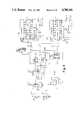
- FIG. 2is a schematic diagram of an optical receiver circuit
- FIG. 3is a schematic diagram of a pulse width to voltage conversion circuit
- FIG. 4is a schematic diagram of a combined range and azimuth circuit
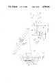
- FIG. 5is a perspective view of a target determining apparatus in accordance with the invention to determine distance, azimuth and binary code identification;
- FIG. 6is a diagrammatic view of the binary code identification system
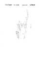
- FIG. 7is a diagram of the returned pulses
- FIG. 8shows a partial circuit for the binary code identification
- FIG. 9is a diagrammatic showing of a shift register memory
- FIG. 10is an enlarged view of the shift register memory
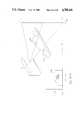
- FIG. 11is a variation of FIG. 5 where azimuth measurement determines direction and distance measurement determines height above the floor;
- FIG. 12shows the inverse operation of determining the distance and location of a shadow object
- FIG. 13is a schematic diagram of the inverted circuit of FIG. 3;
- FIG. 14shows a gauging application as a direct consequence of the inverse operation
- FIG. 15shows a web scanning width application using the shadow of the web material at a known distance
- FIG. 16shows a continuous profiling operation based on a moving target, providing a continuously variable shadow width which represents target size
- FIG. 16Ashows a graph of the object profile
- FIG. 17shows a perimeter and area object detection system
- FIG. 18shows a flow chart for software to perform the hardware operation of FIG. 4;
- FIG. 19shows a flow chart for center of target calculation
- FIGS. 20A-20Dshow variations of target reflectors and target shadows for use in complementary application.
- the drawingillustrates a target determining apparatus 11 which embodies the present invention.
- This apparatus 11includes a light source 12 which is preferably of columnated light such as a laser. This laser may be mounted inside a housing 13 for protection of the components.
- a rotatable motor 14 and a mirror 15provides a means to scan a light beam from this light source 12 along a scanning path 16 at a known rate of angular velocity.
- this scanning pathis in a horizontal plane because of a vertical motor axis and the 45-degree angle disposition of the mirror.
- This mirroris preferably a front surface mirror so that the scanning beam is narrow in the direction of the scanning path 17. In the preferred embodiment, this scanning path extends radially from the rotatable mirror 15.
- a part or all of the housing 13has a transparent window 18 so that the light beam may scan all or part of a 360-degree scanning path 17.
- a target 20has leading and trailing edges, relative to the light beam scan, which are boundaries between a retroreflector and a non-retroreflector.
- the targetis a retroreflector of a known size, is adapted to be mounted on an object 21, as in FIG. 5, and is adapted to be mounted in the scanning path to reflect the beam of light from the light source 12 back toward the scanning mirror 15.
- a first photoreceptor 22is positioned to be responsive to any reflected light beam 16 from the target reflector and, as FIG. 1 shows, this photoreceptor is positioned closely adjacent the light source 12.
- the target retroreflectoris a device with the characteristic to return an incident light beam along it original axis, independent of axial incidence to the plane of the reflector.
- the returned beam of light 16Ais somewhat dispersed, and is not quite as columnated as the incident beam 16.
- the returned beam of light 16Ainstantaneously impinges the same rotating mirror 15, and reflects the returned beam back to the light source 12.
- this returned beamis less columnated than the original, it can impinge a photoreceptor 22, which in practical terms is close to, but not coincident with, the output beam of light source 12.
- An electronic circuit 23is connected to the receptor 22 to determine the position of the target or information about the target.
- the motor 14rotates the mirror 15 at a constant angular velocity. This may be anything practicable for the intended use and 20 revolutions per second is an example of the appropriate rate of scan.
- FIG. 1shows this target at a first distance from the scanning mirror and also shows the mirror at a second position 20A positioned closer to the scanning mirror. If one used a four-inch wide retroreflector target 20 and it was positioned at ten feet distance, this might take five milliseconds to scan from the leading to the trailing edges of this target. However, if the same width target is positioned at 20A at one-half the distance or five feet distance from the mirror, then at the same rate of scan it will take ten milliseconds to scan from the leading to the trailing edge of this target. This is in accordance with the proportionality of:
- the apparatuspermits one to determine the distance to a target by the length of time for scanning across the target and it will be noted that the distance to the target is inversely related to the length of time of scan across the target.
- the electronic circuit 23 or softwareis capable of calculating this distance to the target. Conversely, if the target distance is known, the target scan width may be determined.
- FIG. 2illustrates an optical receiver circuit 24, and FIG. 3 illustrates a pulse width to voltage circuit 25 which together make up the circuit 23.
- the photoreceptor 22is shown as a phototransistor, with the signal being amplified by transistors 28 and 29 and then fed to an operational amplifier 30 which is connected as a comparator to obtain a square pulse output at the terminal 31.
- This pulseis applied at the terminal 31 of a range switch 32 in the pulse width to voltage circuit 25 of FIG. 3. With this range switch in the position shown, the input pulse is applied to an enable terminal 33 of a divider 34.
- a high frequency oscillator 35for example, four megahertz, is controlled by a crystal 36, and this signal is fed through a series of inverter gates 37 to square the oscillator signal and then is supplied to a clock input 38 of the divider 34.
- the enable input and clock input 38form an AND circuit with output from the divider being produced only when the enable and clock inputs are a logic high.
- the output from the divider 34is passed to a second divider 40 to obtain a lower frequency, 200 kilohertz as an example.
- This lower clock frequencyis supplied to the clock input of a counter 41, for example, a 12-stage counter with the output being on a plurality of lines 42 and appearing as a binary number. This plural lines are connected to latches 43 and 44 which hold the last count from the counter 41.
- the pulse signal at terminal 33is also applied through monostable multivibrators 46 and 47 to obtain a short pulse, for example, 100 microseconds, which is applied to the clock terminals of the latches 43 and 44 and hence clocks the information of the latches into a digital-to-analog conversion unit 50.
- the pulse on the photoreceptor 22acts through monostable multivibrators 48 and 49 in series to reset the counter 41.
- the signal from the latch 43is on plural lines 51 and is the most significant bit of a binary number, whereas the signal from the latch 44 is on plural lines 52 and is the least significant bit presented to the D/A converter 50.
- the output of the D/A converter 50is an analog voltage amplified by amplifier 54 and is then passed to a unity gain voltage follower 55 and then to a meter such as a volt meter 56.
- the electronic circuit 23operates to determine range or distance to the target by determining the length of time between the light beam reflection from the leading and trailing edges of the reflector 20.
- the oscillatoris operating at four megahertz
- the output from the divider 40is 200 kilohertz
- the length of scan from the leading to trailing edges of this target reflectoris five milliseconds at a 10-foot distance of the target.
- This logic highis transferred to FIG. 3 and applied to the enable terminal 33 of a divider 34.
- the terminals 33 and 38 of this divider 34form an AND circuit so that during the time that light is reflected from the target 20, the pulses from the oscillator 35 will be supplied as an input to the dividers 34 and 40.
- These 1000 pulseswill be transformed to a binary number and applied to the digital-to-analog converter.
- the binary equivalent of the decimal number 1000will then be applied at the output of the converter to the input of the amplifier 54. Assume that this is 2 volts, merely as an example.
- the amplifier 54in conjunction with D/A converter 50, inverts so that the output has a one-half volt output.
- the amplifier 55operates as a unity gain voltage follower so that one-half volt is applied to the volt meter 56. This meter could be calibrated to show distance in feet, e.g., 10 feet for a one-half volt input.
- the targetwill appear to be twice as wide, and it will take 10 milliseconds to scan across the width of this target. During this 10 milliseconds of scan width, there will be 2000 pulses applied to the counter 41 and hence the output of the converter 50 will be four volts instead of two volts. Since the amplifier 54 is connected to a multiplying D/A converter 50 in such a way that an increase in the value of the binary input signal to the D/A gives a decrease in the output of amplifier 54 according to the "1 divided by X" relationship, the output will be one-fourth of a volt applied to the meter 56 instead of one-half volt.
- the apparatus 11determines the range or distance to the target, and this distance is inversely related to the length of time of the scan of the width of the target.
- the circuits of FIGS. 2 and 3each demonstrate one embodiment of a functional operation. Other, more or less elaborate circuits can be designed to perform the functions of providing a digital signal representing the status of returned light, as is done in FIG. 2, and pulse width conversion to an analog voltage, as is done in FIG. 3. Indeed, an integrated optoelectronic switch, the Sprague ULN-3330, can be substituted for the circuit in FIG. 2.
- the D/A converter 50would not be used, and the digital count, contained in the 12-stage counter 41, can be brought out directly to provide total digital representation of range to an intelligent control device, such as a microprocessor-based control system.
- the function of the D/A converter 50 that is perform the mathematical inverse operation to make the output signal proportional with distancecan, in this case, be computed internally within the microprocessor control through a software implementation of the inverse calculation.
- the target determining apparatus 11may also be utilized to determine the azimuthal position of the target relative to a known azimuthal reference.
- FIG. 1shows a second photoreceptor 62 at a known azimuth and located within the instrument housing, e.g., at the edge of the window 18, and this may be considered a reference zero degrees.
- the motor 14may rotote in either direction and is shown as rotating clockwise with the target at about a 45-degree angle relative to this reference zero position.
- the circuit of FIG. 3may be utilized.
- the range switch 32may be switched upwardly to an azimuth terminal 63 which is driven from the Q output of a flip-flop 64 to which the first and second photoreceptors 22 and 62 are each connected through an optical receiver circuit like that in FIG. 2, to the R and S inputs, respectively.
- a second set of switch contacts 32Aswitch the D/A converter from an inversion function (1 divided by X) to a linear function.
- the length of time that the laser beam sweeps from the reference position to the beginning of scan of the retroreflectoris proportional to the azimuthal position of this target.
- clock pulsesare counted by the counter 41 until the beam sweeps past the target retroreflector 20.
- Thiscauses an input at the R input of the flip-flop 64 to switch it back to a logic zero output and stop the count.
- the counternow contains a binary count representing time.
- the digital-to-analog converter 50converts this into an analog voltage representing azimuth.
- azimuth (angle)is directly related to the time period between the pulse from a circuit of FIG. 2 driven from photoreceptor 62 and the pulse from another copy of the circuit of FIG. 2 driven from photoreceptor 22.
- the amplifier 54can be connected to the multiplying D/A converter 50 in a slightly different way to generate the linear rather inverse relationship.
- the reset and store signals from the monostable multivibrators 46-49cause the counters and latches to operate in a repeating mode.
- FIG. 4shows the most recent analog design for combining the functions of range, width, and azimuth into one simultaneous system.
- the optical receivers, previously described in FIG. 2, and photoreceptors 22 and 62are replaced with optoelectric integrated circuits 100 and 100A.
- the crystal oscillator 36is replaced with an integrated circuit device 101.
- the range circuitry shown in FIG. 3is again shown with counter 102 and D/A 103.
- the azimuth circuitryconsists of counters 105 and D/A 106.
- FIG. 18shows a flow chart for implementing the logic functions in software using a microprocessor-based control.
- the apparatus 11may be used not only to determine the azimuth, width and range of the target, but also to identify which of several targets is being scanned.
- FIG. 5illustrates these three different capabilities of the apparatus 11.
- Automated guided vehicles 70 and 71each have a motor 72 therein to provide locomotion of such vehicle. Such vehicles may move along a roadway 73 and be guided in operation by the apparatus 11.
- a scanner housing 74may be mounted on the front of each vehicle to scan a fixed target 20 for azimuth position and distance; may scan a retroreflector target 75 on the rear of each vehicle in order to maintain a safe distance between successive vehicles; and may scan a binary coded fixed target 76 along the roadway 73 in order to determine information about the location of the vehicle relative to its position along the roadway 73.
- a scanner housing 78may be mounted in a fixed location along the side of the roadway in order to scan binary-coded targets 80 and 81 on the vehicles 70 and 71, respectively.
- the binary code on the targets 76, 80, and 81may be a pure binary code, or may be a type of a bar code.
- the binary-coded targetsare ones which have retroreflective stripes at both the leading and trailing edges 82 and 83, respectively.
- FIG. 6illustrates diagrammatically the target determining apparatus 11 wherein the binary coded target such as targets 76, 80, or 81 is identified.
- the binary coded target 81 shown in FIG. 6has a plurality of reflective and nonreflective strips transverse to the scanning path 17 to establish binary indicia on the target.
- the electronic circuit 23 connected to the photoreflector 22is adapted to read the binary indicia on this target 81.
- This targetis shown as having a reflective strip at both the leading edge 82 and the trailing edge 83.
- FIG. 7illustrates the binary indicia present on the returned pulse from scanning the width of the target.
- FIG. 7illustrates a return pulse 85 from the reference azimuth photoreceptor 62, and hence the distance in time between the reference pulse 85 and the leading edge of the target still obtains the azimuthal position of the target.
- the entire width of the targetmay still be used to determine range or distance; if the distance is known, the target width may be determined and the binary code may be utilized to provide information about the target.
- the total width of the retroreflector 81has been divided into n equal width fields and in this example has been divided into 10 such fields for an 8-bit binary code number.
- the fields zero and 9 in this embodimentare always reflective for a logic one condition. This allows the target reflector to be utilized for ranging as well.
- the 8-bit binary codegives 256 unique identification codes. If two or more black fields occur in succession, they are continuous. Also, reflective fields which occur in succession are continuous. It will be appreciated that as the target moves closer to or away from the scanning mirror, the time width of the coded pulses is likewise expanded or contracted. To decode the pattern, the pattern must be analyzed for relative values for each field within the combined ensemble.
- One way to do thisis to digitally store the pattern in a memory device, either a shift register or a microprocessor memory.
- the total time widthis determined similar to that as done to determine range, and then the pulse structure is analyzed to determine the value, whether a logic one or a zero, at or near the center of each field.
- This functionmay be performed by a microprocessor or by hardware.
- FIG. 5shows that the pulse pattern is transferred from the scanner housing 78 into a memory 89 and then operated on by a microprocessor 90 and fed to a decoder 91.
- decodersare commercially available such as a bar decoder.
- FIGS. 8, 9, and 10illustrate such an embodiment.
- the total pulse width indicating range from the bar coded reflectoris one millisecond at 10 feet and 10 milliseconds at one foot distance.
- the precise width of the total pulseis not known because the range is still unknown. If one assumes for this example a maximum range of 10 feet, then each field is 0.1 milliseconds in scan width as a minimum.
- FIG. 8shows a storage device in the form of a shift register 94 or this may be a microprocessor memory.
- the shift register 94samples the waveform in time and stores that value as either a logic one or a zero.
- a minimum time t 0is one millisecond, and with an assumed maximum desired error of 1%, the target is sampled and the value stored is X(t), with sampling at one millisecond divided by 100 increments, or at each 10 microseconds. Since X(t) can last up to 10 milliseconds plus any delay due to azimuth, at one foot distance of the reflector could be positioned at zero degrees to some other angle, and then some extra time must be accounted for.
- the 2000 stage shift registeris commercially available in integrated circuit form.
- the procedurestarts when the azimuth reference signal is received from the photoreceptor 62 and establishes the reference pulse 85.
- the shift registerstores the first sampling at the 10-microsecond point in memory position No. 1 and 10 microseconds later, a clock pulse causes the memory location No. 1 to be placed into memory location No. 2 while putting the new present value of X(t) into memory location No. 1. This continues, and in fact all memory locations are shifted in this matter. So if n t represents the time at the nth increment of 10 microseconds, then the shift register has 2000 memory locations, each having a memory location X(n t ).
- the shift registertherefore, contains a sampled image of the returned pulse X(t) waveform, but in a digitized state. After 2000 steps, the clock 95 stops, and the stored data must be analyzed.
- the memory map of the shift registerappears something like that shown in FIG. 9. The first thing determined is t 0 . It is known that fields 0 and 9 are logic ones, and on FIG. 9 these are represented by the black lines. Starting from the left, the shift register contains all zeros until the reflector pattern is reached.
- the circuit components for one practical system combining FIGS. 2 and 3 circuit which has been constructedare set forth in the following table:
- FIG. 11shows an application for use of this apparatus to guide automatic vehicles, similar to the configuration of FIG. 5, but in a vertical orientation.
- vehicle 120has mounted to it the said scanning apparatus 121 mounted so that it scans towards the floor.
- Attached to the flooris a continuous strip of retroreflective tape 122 which is used to guide the steering direction of the vehicle.
- the apparatus 121scans downward at the floor, and the retroreflective tape is detected at some specific point in the scan as determined by the azimuth or angle measurement as described above.
- the position of the tapeis detected as an angle readout, and the information is sent to an appropriate guidance controller, so as to track the tape.
- a possible algorithmwould be to adjust the steering of the vehicle such that the detected angle of the tape is always at a point halfway between the two scan extremes, i.e., at 0 degrees from the normal to the front of the apparatus.
- the vehicle heightis measured using the incorporated feature of the measurement of distance to a retroreflector target. This important, since many vehicles need to position the vertical height of their load to accommodate transfer to a waiting station. The advantage here is that no additional hardware is needed to accomplish this second task.
- FIG. 12shows that the complementary operation for detecting distance and angle to a fixed width retroreflective target is possible.
- a fixed width non-reflective targetis scanned and processed similar to that of the reflective target.
- a long retroreflective strip 123longer than full scan capability of the apparatus, is continually scanned with the narrow light beam from the apparatus 11.
- a fixed width opaque target 124similar to target 20A of FIG. 1, is placed in the field of scan, it can be located with regard to angle and distance if the inverse of reflection is used as the target signal.
- a shadow 125is developed on retroreflector 123 where no light is returned to the apparatus 11. This is analogous to reflecting light only from the target, but here the absence of light is used as the signal rather than the presence of light.
- FIG. 13a digital logic inverter 126 is added to produce the complementary signal, i.e., a logic level "1" when there is no light due to a shadow due to a scan from the leading to the trailing edge across the target. This is with an inverting switch 127 in the position shown. When thrown to the alternate position, the circuit is usable for retroreflective targets, as in FIG. 2. Of course, this logic inversion can also be accomplished in software.
- FIG. 14follows the inverse operation of the shadow mode given in FIG. 13 for a particular application of measuring the diameter of an object. If an object whose width is a variable quantity is placed at a fixed distance from the apparatus 13, then the variation of the diameter of the object manifests itself in a variation in the scanning time of the shadow. Object 128 projects a smaller shadow than an object 129, and therefore can be measured by the time of non-reflective scan.
- Fixed-distance targetsexhibit the mathematical behavior of relating their diameter with a direct relationship with the time to scan across the target. A trigonometric compensation for the tangent of the angle is required, and may be built into the software, when accurate measurements are needed and the target produces a shadow greater than 20 degrees of view.
- FIG. 15demonstrates another application of the use of the inverse target mode, that of scanning a web of material for dimensional measurements.
- the scanning apparatus 11is looking down across a moving sheet of material 131. Beneath this material is a retroreflector strip 123 which exceeds the width of the material and yet includes the beginning and end of the scan. Since the material sheet 131 is placed at a fixed distance from the scanning apparatus 11, then any variation in width of the web is detected by the scanner per the procedure described in FIG. 18 below.
- FIG. 16demonstrates a further variation of fixed distance scanning, that of profile scanning a moving object.
- the sensore.g., on a conveyor 134
- the inverse light modeis being used.
- the angle measurementis being used to determine the position of the leading edge of the container target. Since light is reflected continuously from the beginning of the scan until the point just before the container prevents light from impinging the strip retroreflector 123, the inverse target mode is interpreted that no target has been detected. When the light beam finally is interrupted by the object, then no light impinges the retroreflector, and no light returns to the scanner 11.
- the inverse target modedetermines this to be the detection of an object. Therefore, the angle position is determined by the previously discussed procedure for the scanning apparatus. A sequence of such readings as the object passes the scanner constitutes a set of data values describing the object's profile. Again, this is a consequence of a fixed distance target.
- FIG. 16Aillustrates how the object profile 135 may be represented as a graph of angle versus time from the data from consecutive scans across the target as it moves on the conveyor.
- FIG. 17extends the ideas presented in FIGS. 12-16 to the general form of target determination and object detection using the inverse light mode.
- a strip retroreflector 137is positioned in some curvilinear path in one location, here being a continuous strip of three sides of a rectangle.
- the scanner 11is located at another location in one corner such that its full scan angle from beginning of scan at point 138 to end of scan at point 139, here nominally 90 degrees, covers the entire field defined by the strip retroreflector and the scanner.
- a second scanner 11Amay be positioned in a third location so as to scan the same general area as reflected to it by retroreflector strip 137.
- the 90-degree scan beginningwould be at point 142 and end at point 143.
- any object 144 which is positioned in this areacan be detected. It can be measured for distance through the normal procedures defined above if its diameter is known. Also, if the object is located at a fixed radial distance from the scanner 11 or 11A, then its diameter can be measured.
- the target azimuth from a referencee.g., at the beginning of scan, may also be determined for each apparatus 11 and 11A.
- the two separate azimuth valuescan give an approximate location position of the target here shown at point 145. Furthermore, if both azimuth and target width information described above derived from each scanner is processed in any general purpose computer, then a two-dimensional measurement of target size and target position can be determined. In FIG. 17, this calculation would determine the exact locations of points 145, 146, 147, and 148. These points describe a box which surrounds target 144. Assuming that there is enough light to reach the furthest corner of the strip retroreflector, then the particular path of the retroreflector strip has no consequence to the measurement performance. This combines the features of object presence detection with either object location or object diameter measurement.
- FIG. 18gives a flow chart of the logic to perform this function. Basically, when the scanning motor positions the scanning beam at the starting position of the scan shown by block 150, the microprocessor tries to detect whether a target has been detected shown by block 151. When the leading edge of a target is sensed, by either the return of reflected light from a retroreflector target or the absence of light produced by a shadow target in the inverse light mode, the microprocessor immediately stores the internal clock value, using block 152, which represents the angular position of the scanning beam at that instant, into a memory location.
- the microprocessornext goes by block 153 immediately and waits to detect the end position of the target, which causes the target to not be in view. When this happens, the microprocessor immediately stores the clock value, using logic block 154, into the next memory location representing the angle at the trailing edge of the target. After this, the microprocessor starts looking for other targets by going back to block 151, and stores additional pairs of angular data values into memory if indeed other targets are detected. When the active scanning angular position reaches the end of the scan as detected by logic block 155, in this case after 90 degrees of scan, the microprocessor then proceeds to process the stored information to determine azimuth and distance for each target detected.
- Process block 156retrieves the first stored angular value and computes azimuth directly in block 157, since azimuth is proportional to this angle datum.
- the second data valueis retrieved by block 158, representing the angle for the trailing edge of the target.
- the first angle valueis subtracted from this second value, and the difference represents time to scan across the target, since the actual time to scan is proportional to this difference.
- Now distancecan be computed in block 159 with the 1/X algorithm either in software, and thus sending direct measure of distance, or by hardware providing this 1/X function in an analog voltage form.
- Block 161will output the appropriate information for each target detected, since block 160 will repeat this function for each target detected.
- Block 162returns the process to the starting position.
- the output functionscan also be provided for in a digital serial form, such as usng a RS-232 specification. The methods for accomplishing this communication are well known by the industry.
- FIG. 18shows how to determine the angle and distance to the target by processing the leading and trailing edge angles of the targets. Other forms of analysis are possible.
- FIG. 19shows an alternative for determining angular direction to the target.
- the azimuthis computed as the center of the target.
- Block 163shows the leading edge clock value is read from memory and entered into a memory "A”.
- Block 164reads from memory the trailing edge clock value and enters it in memory "B”.
- Block 165takes the average value of the leading and trailing edges of the target, and is a substitute for block 157.
- Other functions of target analysisare possible, since only a software substitution for block 165 and/or block 166 need be made, with block 166 a substitute for block 159.
- Other functionsinclude (1) ignoring the target if its distance is too far, such as "A"-"B" is too small, or (2) only processing the first, last, or nth angular data pair for multiple targets, or (3) processing a variable distance bar-coded target in software by performing the hardware solution of target identification given by FIGS. 6 through 10, using equivalent software operations. Indeed, once the fundamental edge values of the targets are available in memory, then the capability of expanding the target determining characteristics may be found by software descriptions of the algorithms.
- FIG. 20gives examples of various target formats which can work with the apparatus.
- FIG. 20Ashows the standard fixed with retroreflector target 170 for basic target aximuth and distance determination.
- the retroreflector 171 shown in FIG. 20Bhas the characteristic of having a circular cross section in the plane of the scan, namely being a cylinder around which a retroreflector is banded in a continuous 360-degree strip.
- This reflector 171can be used to eliminate directional characteristics of the flat target of FIG. 20A.
- the center-of-target angle algorithm discussed with relation to FIG. 19would be most appropriate for automatic guided vehicle applications shown in FIG. 5.
- Target 20 in FIG. 5can be replaced with this configuration of FIG. 20B for some applications.
- the target 172 in FIG. 20Cshows a variation of a circular cross section retroreflector target, in the shape of a cone.
- the vertical motion of this targetwill be detected as an angular width change, and consequently height can be determined.
- a tape strip 173 of retroreflector materialcan be used with the application in FIG. 11. Its width will initiate height measurements, while its physical placement on the floor can cause a directing function for vehicle navigation. Other forms of these retroreflector targets can be determined with regard to specific applications.
Landscapes
- Physics & Mathematics (AREA)
- Engineering & Computer Science (AREA)
- Electromagnetism (AREA)
- General Physics & Mathematics (AREA)
- Radar, Positioning & Navigation (AREA)
- Remote Sensing (AREA)
- Computer Networks & Wireless Communication (AREA)
- Optical Radar Systems And Details Thereof (AREA)
Abstract
Description
angle α(width/distance).
______________________________________ Resistances Amplifiers R1 1.5Kohms 30 TL07154, 55 TL071 R3 820 ohms R4 220 ohms R5-R8 100K ohms Diodes R9 6.8 M ohms D1 IN914 R10 10K ohms Capacitors Gates C1, R2 22K ohms C2 10pf 37 400122, 62 Transistors Integrated Circuits 34, 40 OP805 4518B 282N4250 414040B 2943, 44 40174 50 AD7533KN 46-49 4538 64 4027B 90 INTEL 8741 91 Welch Allyn LTS-3 94 AM2533 ______________________________________ 2N5088
______________________________________ Integrated Circuits ______________________________________ 100,102, 105 4040 103, 106 100A ULN3330 104, 107 AD7533KN 108, 109 4538 110, 111 4013 112 4017 ______________________________________ TL071
Claims (30)
Priority Applications (1)
| Application Number | Priority Date | Filing Date | Title |
|---|---|---|---|
| US07/098,408US4788441A (en) | 1985-12-16 | 1987-09-17 | Range finder wherein distance between target and source is determined by measuring scan time across a retroreflective target |
Applications Claiming Priority (2)
| Application Number | Priority Date | Filing Date | Title |
|---|---|---|---|
| US80911985A | 1985-12-16 | 1985-12-16 | |
| US07/098,408US4788441A (en) | 1985-12-16 | 1987-09-17 | Range finder wherein distance between target and source is determined by measuring scan time across a retroreflective target |
Related Parent Applications (1)
| Application Number | Title | Priority Date | Filing Date |
|---|---|---|---|
| US80911985AContinuation-In-Part | 1985-12-16 | 1985-12-16 |
Publications (1)
| Publication Number | Publication Date |
|---|---|
| US4788441Atrue US4788441A (en) | 1988-11-29 |
Family
ID=26794711
Family Applications (1)
| Application Number | Title | Priority Date | Filing Date |
|---|---|---|---|
| US07/098,408Expired - Fee RelatedUS4788441A (en) | 1985-12-16 | 1987-09-17 | Range finder wherein distance between target and source is determined by measuring scan time across a retroreflective target |
Country Status (1)
| Country | Link |
|---|---|
| US (1) | US4788441A (en) |
Cited By (44)
| Publication number | Priority date | Publication date | Assignee | Title |
|---|---|---|---|---|
| US4967064A (en)* | 1989-06-30 | 1990-10-30 | Tennant Company | Method and apparatus for a target determining apparatus having increased range |
| US4997283A (en)* | 1989-03-27 | 1991-03-05 | Danielson Glen C | Vehicle straightener measuring unit, measuring apparatus reliant on reflected beams, and source, targets and method |
| US5221956A (en)* | 1991-08-14 | 1993-06-22 | Kustom Signals, Inc. | Lidar device with combined optical sight |
| US5237164A (en)* | 1989-05-12 | 1993-08-17 | Sony Corporation | Card having retroreflective bar codes and a magnetic stripe |
| US5313069A (en)* | 1991-12-31 | 1994-05-17 | Trimble Navigation | Distance measuring system of an extendable strip having light reflecting and non-reflecting polygons |
| US5328190A (en)* | 1992-08-04 | 1994-07-12 | Dart International, Inc. | Method and apparatus enabling archery practice |
| US5336899A (en)* | 1992-11-24 | 1994-08-09 | The United States Of America As Represented By The Secretary Of The Army | Adjustable near infrared rangefinder illuminator |
| US5353228A (en)* | 1991-03-05 | 1994-10-04 | Carl-Zeiss-Stiftung, Heidenheim/Brenz | Range-finding method and apparatus |
| WO1995029380A1 (en)* | 1994-04-20 | 1995-11-02 | Siman Sensors & Intelligent Machines Ltd. | Navigation system for fast automated vehicles and mobile robots |
| US5467273A (en)* | 1992-01-12 | 1995-11-14 | State Of Israel, Ministry Of Defence, Rafael Armament Development Authority | Large area movement robot |
| US5512761A (en)* | 1993-09-22 | 1996-04-30 | Siemens Aktiengesellschaft | Distance sensor for determining a distance between two relatively movable members by measuring a time during which a measuring mark is in a light path between a light transmitter and a light receiver |
| US5649706A (en)* | 1994-09-21 | 1997-07-22 | Treat, Jr.; Erwin C. | Simulator and practice method |
| WO1997039394A1 (en)* | 1996-04-15 | 1997-10-23 | Apogeum Ab | A method for determining the positions of a plurality of anonymous fixed reference objects for mobile surface transportation and a device for determining said positions |
| EP0849608A3 (en)* | 1996-12-20 | 1998-08-19 | FIFE GmbH | Device for determining the position of the edge of a moving belt |
| US5823779A (en)* | 1996-05-02 | 1998-10-20 | Advanced Interactive Systems, Inc. | Electronically controlled weapons range with return fire |
| US5875408A (en)* | 1995-07-17 | 1999-02-23 | Imra America, Inc. | Automated vehicle guidance system and method for automatically guiding a vehicle |
| US5910767A (en)* | 1997-07-11 | 1999-06-08 | Laser Guard | Intruder detector system |
| US5947738A (en)* | 1996-08-26 | 1999-09-07 | Advanced Interactive Systems, Inc. | Simulated weapon with gas cartridge |
| US6115128A (en)* | 1997-09-17 | 2000-09-05 | The Regents Of The Univerity Of California | Multi-dimensional position sensor using range detectors |
| US6142375A (en)* | 1998-04-10 | 2000-11-07 | 3M Innovative Properties Company | Apparatus and method for the optical detection of multiple items on a platform |
| WO2000071970A1 (en)* | 1999-05-26 | 2000-11-30 | Hand Held Products, Inc. | Portable laser scanner |
| US6575753B2 (en) | 2000-05-19 | 2003-06-10 | Beamhit, Llc | Firearm laser training system and method employing an actuable target assembly |
| US6579098B2 (en) | 2000-01-13 | 2003-06-17 | Beamhit, Llc | Laser transmitter assembly configured for placement within a firing chamber and method of simulating firearm operation |
| US6616452B2 (en) | 2000-06-09 | 2003-09-09 | Beamhit, Llc | Firearm laser training system and method facilitating firearm training with various targets and visual feedback of simulated projectile impact locations |
| US20030175661A1 (en)* | 2000-01-13 | 2003-09-18 | Motti Shechter | Firearm laser training system and method employing modified blank cartridges for simulating operation of a firearm |
| US20040135990A1 (en)* | 2002-10-18 | 2004-07-15 | Fumio Ohtomo | Position measuring instrument |
| EP1191306A3 (en)* | 2000-09-26 | 2004-12-15 | Fuji Photo Film Co., Ltd. | Distance information obtaining apparatus and distance information obtaining method |
| US20050052635A1 (en)* | 2003-09-04 | 2005-03-10 | Tong Xie | Method and system for optically tracking a target using a triangulation technique |
| US20060060651A1 (en)* | 2004-09-23 | 2006-03-23 | Mcintyre Timothy J | Laser scanning system for object monitoring |
| US20060126059A1 (en)* | 2002-01-09 | 2006-06-15 | Groothuis David S | Laser scanner with parabolic collector |
| US20070182587A1 (en)* | 2003-05-22 | 2007-08-09 | Christian Danz | Method and device for detecting objects in the surroundings of a vehicle |
| US7329127B2 (en) | 2001-06-08 | 2008-02-12 | L-3 Communications Corporation | Firearm laser training system and method facilitating firearm training for extended range targets with feedback of firearm control |
| US20100182588A1 (en)* | 2007-01-29 | 2010-07-22 | Gerd Reime | Method and device for determining the distance to a retroreflective object |
| US20100265216A1 (en)* | 2009-04-17 | 2010-10-21 | Raydium Semiconductor Corporation | Optical touch apparatus and operating method thereof |
| US20120218564A1 (en)* | 2011-02-24 | 2012-08-30 | Sick Ag | Method for the secure detection and position determination of objects and safety apparatus |
| WO2014033425A3 (en)* | 2012-08-31 | 2014-07-17 | Reflex Imaging Limited | Position determination |
| US20140312749A1 (en)* | 2013-04-23 | 2014-10-23 | Jenoptik Robot Gmbh | Device for a system for traffic monitoring of vehicles in road traffic |
| US20140368837A1 (en)* | 2012-02-20 | 2014-12-18 | Korea Railroad Research Institute | Absolute position detection system |
| US9163936B1 (en)* | 2012-05-07 | 2015-10-20 | Physical Optics Corporation | Three-dimensional profilometer |
| US20160116131A1 (en)* | 2014-10-24 | 2016-04-28 | Hyundai Motor Company | Turn signal lamp device using laser |
| DE102015008310A1 (en)* | 2015-06-30 | 2017-01-05 | Wabco Gmbh | Sensor device for environmental detection and method for detecting a zero point position of a rotatable unit of such a sensor device |
| US20210103041A1 (en)* | 2018-05-30 | 2021-04-08 | Fujifilm Corporation | Signal detection system |
| WO2022147391A1 (en)* | 2020-12-28 | 2022-07-07 | Plx, Inc. | Tracking laser range finder system and method |
| US12274421B2 (en) | 2020-02-17 | 2025-04-15 | Novelbeam Technology Inc. | Device for anti-fog endoscope system |
Citations (26)
| Publication number | Priority date | Publication date | Assignee | Title |
|---|---|---|---|---|
| US3324383A (en)* | 1961-09-28 | 1967-06-06 | Gen Motors Corp | Dynamoelectric machine |
| US3434785A (en)* | 1964-05-18 | 1969-03-25 | Lear Siegler Inc | Beam sweeping optical distance meter |
| US3530468A (en)* | 1968-02-23 | 1970-09-22 | Rca Corp | Triangulation radar system |
| US3749500A (en)* | 1970-12-23 | 1973-07-31 | Gen Electric | Optical caliper and edge detector-follower for automatic gaging |
| FR2186658A1 (en)* | 1972-03-13 | 1974-01-11 | Thomson Csf | |
| US4025193A (en)* | 1974-02-11 | 1977-05-24 | The Boeing Company | Apparatus suitable for use in orienting aircraft in-flight for refueling or other purposes |
| US4029415A (en)* | 1975-02-03 | 1977-06-14 | Dakota Electron, Inc. | Laser land-surveying apparatus with digital display |
| US4119379A (en)* | 1967-09-27 | 1978-10-10 | Sanders Associates, Inc. | Optical detection and ranging apparatus |
| US4184767A (en)* | 1975-07-21 | 1980-01-22 | The United States Of America As Represented By The Secretary Of The Navy | Frequency agile optical radar |
| US4192612A (en)* | 1976-01-09 | 1980-03-11 | Siemens Aktiengesellschaft | Device for contact-free thickness measurement |
| US4212534A (en)* | 1977-09-30 | 1980-07-15 | Siemens Aktiengesellschaft | Device for contact-free measuring of the distance of a surface of an object from a reference plane |
| US4225226A (en)* | 1978-12-29 | 1980-09-30 | Spectra-Physics, Inc. | Laser guidance system for crop spraying aircraft |
| US4239388A (en)* | 1974-07-29 | 1980-12-16 | The United States Of America As Represented By The Secretary Of The Air Force | Time domain laser reconnaissance technique |
| US4268167A (en)* | 1979-01-08 | 1981-05-19 | Alderman Robert J | Distance measuring system |
| US4325638A (en)* | 1979-04-27 | 1982-04-20 | Tokyo Kogaku Kikai Kabushiki Kaisha | Electro-optical distance measuring apparatus |
| FR2495797A1 (en)* | 1980-12-09 | 1982-06-11 | Onera (Off Nat Aerospatiale) | Laser-optic automatic positioning for electric vehicle - uses fixed reference of three retro-reflectors and measures angle of reflected light to position vehicle |
| US4336997A (en)* | 1979-03-06 | 1982-06-29 | Erwin Sick Gmbh Optik-Electronik | Change of distance measuring apparatus |
| US4417816A (en)* | 1980-08-11 | 1983-11-29 | Colt Industries Operating Corp. | Laser measuring system and method for turning machine |
| US4441809A (en)* | 1979-10-16 | 1984-04-10 | Dudley James R | Method and apparatus for determining position |
| US4443078A (en)* | 1981-03-31 | 1984-04-17 | Canon Kabushiki Kaisha | Distance detecting device in a camera |
| US4453085A (en)* | 1981-05-11 | 1984-06-05 | Diffracto Ltd. | Electro-optical systems for control of robots, manipulator arms and co-ordinate measuring machines |
| JPS5999308A (en)* | 1982-11-30 | 1984-06-08 | Komatsu Ltd | Distance measuring sensor |
| GB2143395A (en)* | 1983-05-14 | 1985-02-06 | Gen Electric Co Plc | Vehicle guidance and control system |
| US4518254A (en)* | 1980-09-22 | 1985-05-21 | The Commonwealth Of Australia | Ocean depth sounding from the air by laser beam |
| US4560270A (en)* | 1981-08-07 | 1985-12-24 | Geotronics Ab | Device included in a distance meter system |
| US4595294A (en)* | 1981-09-26 | 1986-06-17 | Nippon Kogaku K.K. | Position detecting device |
- 1987
- 1987-09-17USUS07/098,408patent/US4788441A/ennot_activeExpired - Fee Related
Patent Citations (26)
| Publication number | Priority date | Publication date | Assignee | Title |
|---|---|---|---|---|
| US3324383A (en)* | 1961-09-28 | 1967-06-06 | Gen Motors Corp | Dynamoelectric machine |
| US3434785A (en)* | 1964-05-18 | 1969-03-25 | Lear Siegler Inc | Beam sweeping optical distance meter |
| US4119379A (en)* | 1967-09-27 | 1978-10-10 | Sanders Associates, Inc. | Optical detection and ranging apparatus |
| US3530468A (en)* | 1968-02-23 | 1970-09-22 | Rca Corp | Triangulation radar system |
| US3749500A (en)* | 1970-12-23 | 1973-07-31 | Gen Electric | Optical caliper and edge detector-follower for automatic gaging |
| FR2186658A1 (en)* | 1972-03-13 | 1974-01-11 | Thomson Csf | |
| US4025193A (en)* | 1974-02-11 | 1977-05-24 | The Boeing Company | Apparatus suitable for use in orienting aircraft in-flight for refueling or other purposes |
| US4239388A (en)* | 1974-07-29 | 1980-12-16 | The United States Of America As Represented By The Secretary Of The Air Force | Time domain laser reconnaissance technique |
| US4029415A (en)* | 1975-02-03 | 1977-06-14 | Dakota Electron, Inc. | Laser land-surveying apparatus with digital display |
| US4184767A (en)* | 1975-07-21 | 1980-01-22 | The United States Of America As Represented By The Secretary Of The Navy | Frequency agile optical radar |
| US4192612A (en)* | 1976-01-09 | 1980-03-11 | Siemens Aktiengesellschaft | Device for contact-free thickness measurement |
| US4212534A (en)* | 1977-09-30 | 1980-07-15 | Siemens Aktiengesellschaft | Device for contact-free measuring of the distance of a surface of an object from a reference plane |
| US4225226A (en)* | 1978-12-29 | 1980-09-30 | Spectra-Physics, Inc. | Laser guidance system for crop spraying aircraft |
| US4268167A (en)* | 1979-01-08 | 1981-05-19 | Alderman Robert J | Distance measuring system |
| US4336997A (en)* | 1979-03-06 | 1982-06-29 | Erwin Sick Gmbh Optik-Electronik | Change of distance measuring apparatus |
| US4325638A (en)* | 1979-04-27 | 1982-04-20 | Tokyo Kogaku Kikai Kabushiki Kaisha | Electro-optical distance measuring apparatus |
| US4441809A (en)* | 1979-10-16 | 1984-04-10 | Dudley James R | Method and apparatus for determining position |
| US4417816A (en)* | 1980-08-11 | 1983-11-29 | Colt Industries Operating Corp. | Laser measuring system and method for turning machine |
| US4518254A (en)* | 1980-09-22 | 1985-05-21 | The Commonwealth Of Australia | Ocean depth sounding from the air by laser beam |
| FR2495797A1 (en)* | 1980-12-09 | 1982-06-11 | Onera (Off Nat Aerospatiale) | Laser-optic automatic positioning for electric vehicle - uses fixed reference of three retro-reflectors and measures angle of reflected light to position vehicle |
| US4443078A (en)* | 1981-03-31 | 1984-04-17 | Canon Kabushiki Kaisha | Distance detecting device in a camera |
| US4453085A (en)* | 1981-05-11 | 1984-06-05 | Diffracto Ltd. | Electro-optical systems for control of robots, manipulator arms and co-ordinate measuring machines |
| US4560270A (en)* | 1981-08-07 | 1985-12-24 | Geotronics Ab | Device included in a distance meter system |
| US4595294A (en)* | 1981-09-26 | 1986-06-17 | Nippon Kogaku K.K. | Position detecting device |
| JPS5999308A (en)* | 1982-11-30 | 1984-06-08 | Komatsu Ltd | Distance measuring sensor |
| GB2143395A (en)* | 1983-05-14 | 1985-02-06 | Gen Electric Co Plc | Vehicle guidance and control system |
Non-Patent Citations (4)
| Title |
|---|
| Lasernet, The Smart Sensor SD/LN1 10M/4 86.* |
| Lasernet, The Smart Sensor SD/LN1 10M/4-86. |
| Patents Abstracts of Japan, vol. 8, No. 215 (P 305) 1652 , Oct. 2, 1984; & JP A 59 99 308 (Komatsu Seisakusho K. K.) 08 06 1984.* |
| Patents Abstracts of Japan, vol. 8, No. 215 (P-305) [1652], Oct. 2, 1984; & JP-A-59 99 308 (Komatsu Seisakusho K. K.) 08-06-1984. |
Cited By (62)
| Publication number | Priority date | Publication date | Assignee | Title |
|---|---|---|---|---|
| US4997283A (en)* | 1989-03-27 | 1991-03-05 | Danielson Glen C | Vehicle straightener measuring unit, measuring apparatus reliant on reflected beams, and source, targets and method |
| US5237164A (en)* | 1989-05-12 | 1993-08-17 | Sony Corporation | Card having retroreflective bar codes and a magnetic stripe |
| US4967064A (en)* | 1989-06-30 | 1990-10-30 | Tennant Company | Method and apparatus for a target determining apparatus having increased range |
| US5353228A (en)* | 1991-03-05 | 1994-10-04 | Carl-Zeiss-Stiftung, Heidenheim/Brenz | Range-finding method and apparatus |
| US5221956A (en)* | 1991-08-14 | 1993-06-22 | Kustom Signals, Inc. | Lidar device with combined optical sight |
| US5313069A (en)* | 1991-12-31 | 1994-05-17 | Trimble Navigation | Distance measuring system of an extendable strip having light reflecting and non-reflecting polygons |
| US5467273A (en)* | 1992-01-12 | 1995-11-14 | State Of Israel, Ministry Of Defence, Rafael Armament Development Authority | Large area movement robot |
| US5328190A (en)* | 1992-08-04 | 1994-07-12 | Dart International, Inc. | Method and apparatus enabling archery practice |
| US5566951A (en)* | 1992-08-04 | 1996-10-22 | Dart International, Inc. | Method and apparatus enabling archery practice |
| US5336899A (en)* | 1992-11-24 | 1994-08-09 | The United States Of America As Represented By The Secretary Of The Army | Adjustable near infrared rangefinder illuminator |
| US5512761A (en)* | 1993-09-22 | 1996-04-30 | Siemens Aktiengesellschaft | Distance sensor for determining a distance between two relatively movable members by measuring a time during which a measuring mark is in a light path between a light transmitter and a light receiver |
| WO1995029380A1 (en)* | 1994-04-20 | 1995-11-02 | Siman Sensors & Intelligent Machines Ltd. | Navigation system for fast automated vehicles and mobile robots |
| US5649706A (en)* | 1994-09-21 | 1997-07-22 | Treat, Jr.; Erwin C. | Simulator and practice method |
| US5875408A (en)* | 1995-07-17 | 1999-02-23 | Imra America, Inc. | Automated vehicle guidance system and method for automatically guiding a vehicle |
| US6012003A (en)* | 1996-04-15 | 2000-01-04 | Apogeum Ab | Method for determining the positions of a plurality of anonymous fixed reference objects for mobile surface transportation and a device for determining said positions |
| WO1997039394A1 (en)* | 1996-04-15 | 1997-10-23 | Apogeum Ab | A method for determining the positions of a plurality of anonymous fixed reference objects for mobile surface transportation and a device for determining said positions |
| US5980254A (en)* | 1996-05-02 | 1999-11-09 | Advanced Interactive Systems, Inc. | Electronically controlled weapons range with return fire |
| US5823779A (en)* | 1996-05-02 | 1998-10-20 | Advanced Interactive Systems, Inc. | Electronically controlled weapons range with return fire |
| US5947738A (en)* | 1996-08-26 | 1999-09-07 | Advanced Interactive Systems, Inc. | Simulated weapon with gas cartridge |
| EP0849608A3 (en)* | 1996-12-20 | 1998-08-19 | FIFE GmbH | Device for determining the position of the edge of a moving belt |
| US5910767A (en)* | 1997-07-11 | 1999-06-08 | Laser Guard | Intruder detector system |
| US6115128A (en)* | 1997-09-17 | 2000-09-05 | The Regents Of The Univerity Of California | Multi-dimensional position sensor using range detectors |
| US6142375A (en)* | 1998-04-10 | 2000-11-07 | 3M Innovative Properties Company | Apparatus and method for the optical detection of multiple items on a platform |
| WO2000071970A1 (en)* | 1999-05-26 | 2000-11-30 | Hand Held Products, Inc. | Portable laser scanner |
| US6373579B1 (en)* | 1999-05-26 | 2002-04-16 | Hand Held Products, Inc. | Portable measurement apparatus for determinging the dimensions of an object and associated method |
| US20030175661A1 (en)* | 2000-01-13 | 2003-09-18 | Motti Shechter | Firearm laser training system and method employing modified blank cartridges for simulating operation of a firearm |
| US6579098B2 (en) | 2000-01-13 | 2003-06-17 | Beamhit, Llc | Laser transmitter assembly configured for placement within a firing chamber and method of simulating firearm operation |
| US6935864B2 (en) | 2000-01-13 | 2005-08-30 | Beamhit, Llc | Firearm laser training system and method employing modified blank cartridges for simulating operation of a firearm |
| US6575753B2 (en) | 2000-05-19 | 2003-06-10 | Beamhit, Llc | Firearm laser training system and method employing an actuable target assembly |
| US6616452B2 (en) | 2000-06-09 | 2003-09-09 | Beamhit, Llc | Firearm laser training system and method facilitating firearm training with various targets and visual feedback of simulated projectile impact locations |
| US6966775B1 (en) | 2000-06-09 | 2005-11-22 | Beamhit, Llc | Firearm laser training system and method facilitating firearm training with various targets and visual feedback of simulated projectile impact locations |
| EP1191306A3 (en)* | 2000-09-26 | 2004-12-15 | Fuji Photo Film Co., Ltd. | Distance information obtaining apparatus and distance information obtaining method |
| US7329127B2 (en) | 2001-06-08 | 2008-02-12 | L-3 Communications Corporation | Firearm laser training system and method facilitating firearm training for extended range targets with feedback of firearm control |
| US20060126059A1 (en)* | 2002-01-09 | 2006-06-15 | Groothuis David S | Laser scanner with parabolic collector |
| US7352455B2 (en) | 2002-01-09 | 2008-04-01 | Chief Automotive Technologies, Inc. | Laser scanner with parabolic collector |
| US20040135990A1 (en)* | 2002-10-18 | 2004-07-15 | Fumio Ohtomo | Position measuring instrument |
| US7515256B2 (en)* | 2002-10-18 | 2009-04-07 | Kabushiki Kaisha Topcon | Position measuring instrument |
| US20070182587A1 (en)* | 2003-05-22 | 2007-08-09 | Christian Danz | Method and device for detecting objects in the surroundings of a vehicle |
| US7729856B2 (en)* | 2003-05-22 | 2010-06-01 | Robert Bosch Gmbh | Method and device for detecting objects in the surroundings of a vehicle |
| US7359041B2 (en)* | 2003-09-04 | 2008-04-15 | Avago Technologies Ecbu Ip Pte Ltd | Method and system for optically tracking a target using a triangulation technique |
| US20050052635A1 (en)* | 2003-09-04 | 2005-03-10 | Tong Xie | Method and system for optically tracking a target using a triangulation technique |
| US7360703B2 (en) | 2004-09-23 | 2008-04-22 | Ut-Battelle, Llc | Laser scanning system for object monitoring |
| US20060060651A1 (en)* | 2004-09-23 | 2006-03-23 | Mcintyre Timothy J | Laser scanning system for object monitoring |
| US20100182588A1 (en)* | 2007-01-29 | 2010-07-22 | Gerd Reime | Method and device for determining the distance to a retroreflective object |
| US8405821B2 (en)* | 2007-01-29 | 2013-03-26 | Gerd Reime | Method and device for determining the distance to a retroreflective object |
| US20100265216A1 (en)* | 2009-04-17 | 2010-10-21 | Raydium Semiconductor Corporation | Optical touch apparatus and operating method thereof |
| US8619061B2 (en)* | 2009-04-17 | 2013-12-31 | Raydium Semiconductor Corporation | Optical touch apparatus and operating method thereof |
| US20120218564A1 (en)* | 2011-02-24 | 2012-08-30 | Sick Ag | Method for the secure detection and position determination of objects and safety apparatus |
| US9199654B2 (en)* | 2012-02-20 | 2015-12-01 | Korea Railroad Research Institute | Absolute position detection system |
| US20140368837A1 (en)* | 2012-02-20 | 2014-12-18 | Korea Railroad Research Institute | Absolute position detection system |
| US9163936B1 (en)* | 2012-05-07 | 2015-10-20 | Physical Optics Corporation | Three-dimensional profilometer |
| WO2014033425A3 (en)* | 2012-08-31 | 2014-07-17 | Reflex Imaging Limited | Position determination |
| US9884208B2 (en) | 2012-08-31 | 2018-02-06 | Reflex Imaging Limited | Position determination |
| US20140312749A1 (en)* | 2013-04-23 | 2014-10-23 | Jenoptik Robot Gmbh | Device for a system for traffic monitoring of vehicles in road traffic |
| US9462706B2 (en)* | 2013-04-23 | 2016-10-04 | Jenoptik Robot Gmbh | Device for a system for traffic monitoring of vehicles in road traffic |
| US20160116131A1 (en)* | 2014-10-24 | 2016-04-28 | Hyundai Motor Company | Turn signal lamp device using laser |
| DE102015008310A1 (en)* | 2015-06-30 | 2017-01-05 | Wabco Gmbh | Sensor device for environmental detection and method for detecting a zero point position of a rotatable unit of such a sensor device |
| US20210103041A1 (en)* | 2018-05-30 | 2021-04-08 | Fujifilm Corporation | Signal detection system |
| US12078761B2 (en)* | 2018-05-30 | 2024-09-03 | Fujifilm Corporation | Signal detection system |
| US12274421B2 (en) | 2020-02-17 | 2025-04-15 | Novelbeam Technology Inc. | Device for anti-fog endoscope system |
| WO2022147391A1 (en)* | 2020-12-28 | 2022-07-07 | Plx, Inc. | Tracking laser range finder system and method |
| US12422527B2 (en) | 2020-12-28 | 2025-09-23 | Plx, Inc. | Tracking laser range finder system and method |
Similar Documents
| Publication | Publication Date | Title |
|---|---|---|
| US4788441A (en) | Range finder wherein distance between target and source is determined by measuring scan time across a retroreflective target | |
| US4764668A (en) | System for locating an object provided with at least one passive target pattern | |
| US4647193A (en) | Optical target ranging apparatus | |
| US4796198A (en) | Method for laser-based two-dimensional navigation system in a structured environment | |
| EP0468677B1 (en) | Three dimensional position sensing system and method | |
| EP0457548B1 (en) | Computer aided positioning system and method | |
| EP0532125B1 (en) | A measuring apparatus for determining the position of a movable element with respect to a reference | |
| Adams et al. | The interpretation of phase and intensity data from AMCW light detection sensors for reliable ranging | |
| US4432648A (en) | Multiple dimension laser gauge | |
| US3809477A (en) | Measuring apparatus for spatially modulated reflected beams | |
| US4622462A (en) | Method and apparatus for three-dimensional scanning | |
| EP0041146A1 (en) | Method and apparatus for determination of angle incidence of electromagnetic energy | |
| JPH04295710A (en) | Method and apparatus for optical angle measurement | |
| US5805286A (en) | Process for determination of the position of a vehicle in a plane of travel | |
| EP0227999B1 (en) | target determining apparatus | |
| EP0057446B1 (en) | Surveying instrument having measuring mode selecting switch means | |
| US3326077A (en) | Optical device employing multiple slit patterns for zero reference in a shaft encoder | |
| US4623797A (en) | Event scanning | |
| GB2173369A (en) | Determining position | |
| GB2173301A (en) | Survey apparatus and method | |
| US5283396A (en) | Calibration of a rotationally scanning position-tracking device | |
| US4867556A (en) | Apparatus for determining the path of a pulsed light beam | |
| JPH09505883A (en) | Equipment for measuring the dimensions of large objects | |
| RU2028645C1 (en) | Optical locator | |
| JP2936074B2 (en) | Optical distance measuring device |
Legal Events
| Date | Code | Title | Description |
|---|---|---|---|
| AS | Assignment | Owner name:ACME-CLEVELAND CORPORATION, A CORP. OF OHIO Free format text:ASSIGNMENT OF ASSIGNORS INTEREST.;ASSIGNOR:LASKOWSKI, EDWARD L.;REEL/FRAME:004803/0208 Effective date:19870914 Owner name:ACME-CLEVELAND CORPORATION,STATELESS Free format text:ASSIGNMENT OF ASSIGNORS INTEREST;ASSIGNOR:LASKOWSKI, EDWARD L.;REEL/FRAME:004803/0208 Effective date:19870914 | |
| FEPP | Fee payment procedure | Free format text:PAYOR NUMBER ASSIGNED (ORIGINAL EVENT CODE: ASPN); ENTITY STATUS OF PATENT OWNER: LARGE ENTITY | |
| CC | Certificate of correction | ||
| AS | Assignment | Owner name:NAMCO CONTROLS CORPORATION Free format text:ASSIGNMENT OF ASSIGNORS INTEREST.;ASSIGNOR:ACME-CLEVELAND CORPORATION, AN OHIO CORP.;REEL/FRAME:005931/0702 Effective date:19911001 | |
| FPAY | Fee payment | Year of fee payment:4 | |
| FEPP | Fee payment procedure | Free format text:PAYOR NUMBER ASSIGNED (ORIGINAL EVENT CODE: ASPN); ENTITY STATUS OF PATENT OWNER: LARGE ENTITY Free format text:PAYER NUMBER DE-ASSIGNED (ORIGINAL EVENT CODE: RMPN); ENTITY STATUS OF PATENT OWNER: LARGE ENTITY | |
| FPAY | Fee payment | Year of fee payment:8 | |
| REMI | Maintenance fee reminder mailed | ||
| LAPS | Lapse for failure to pay maintenance fees | ||
| FP | Lapsed due to failure to pay maintenance fee | Effective date:20001129 | |
| AS | Assignment | Owner name:DYNAPAR CORPORATION, ILLINOIS Free format text:ASSIGNMENT OF ASSIGNORS INTEREST;ASSIGNOR:NAMCO CONTROLS CORPORATION;REEL/FRAME:011506/0330 Effective date:20010108 | |
| STCH | Information on status: patent discontinuation | Free format text:PATENT EXPIRED DUE TO NONPAYMENT OF MAINTENANCE FEES UNDER 37 CFR 1.362 |