US4787927A - Fabrication of optical fibers - Google Patents
Fabrication of optical fibersDownload PDFInfo
- Publication number
- US4787927A US4787927AUS07/064,943US6494387AUS4787927AUS 4787927 AUS4787927 AUS 4787927AUS 6494387 AUS6494387 AUS 6494387AUS 4787927 AUS4787927 AUS 4787927A
- Authority
- US
- United States
- Prior art keywords
- dopant
- fabricating
- chamber
- preform according
- fibre
- Prior art date
- Legal status (The legal status is an assumption and is not a legal conclusion. Google has not performed a legal analysis and makes no representation as to the accuracy of the status listed.)
- Expired - Lifetime
Links
- 238000004519manufacturing processMethods0.000titleclaimsabstractdescription26
- 239000013307optical fiberSubstances0.000titleabstractdescription8
- 239000002019doping agentSubstances0.000claimsabstractdescription54
- 239000000463materialSubstances0.000claimsabstractdescription24
- 239000011521glassSubstances0.000claimsabstractdescription17
- 238000000151depositionMethods0.000claimsabstractdescription16
- 239000007787solidSubstances0.000claimsabstractdescription14
- 238000010438heat treatmentMethods0.000claimsabstractdescription12
- 239000000203mixtureSubstances0.000claimsabstractdescription11
- 238000000034methodMethods0.000claimsdescription21
- 150000002500ionsChemical class0.000claimsdescription13
- 239000012535impuritySubstances0.000claimsdescription10
- 230000003287optical effectEffects0.000claimsdescription9
- 229910052761rare earth metalInorganic materials0.000claimsdescription9
- 229910052691ErbiumInorganic materials0.000claimsdescription6
- 229910052779NeodymiumInorganic materials0.000claimsdescription6
- QEFYFXOXNSNQGX-UHFFFAOYSA-Nneodymium atomChemical group[Nd]QEFYFXOXNSNQGX-UHFFFAOYSA-N0.000claimsdescription5
- 229910052771TerbiumInorganic materials0.000claimsdescription4
- UYAHIZSMUZPPFV-UHFFFAOYSA-NerbiumChemical group[Er]UYAHIZSMUZPPFV-UHFFFAOYSA-N0.000claimsdescription4
- GZCRRIHWUXGPOV-UHFFFAOYSA-Nterbium atomChemical group[Tb]GZCRRIHWUXGPOV-UHFFFAOYSA-N0.000claims2
- 229910052723transition metalInorganic materials0.000claims1
- 229910006113GeCl4Inorganic materials0.000abstract1
- 229910052909inorganic silicateInorganic materials0.000abstract1
- IEXRMSFAVATTJX-UHFFFAOYSA-NtetrachlorogermaneChemical compoundCl[Ge](Cl)(Cl)ClIEXRMSFAVATTJX-UHFFFAOYSA-N0.000abstract1
- 239000000835fiberSubstances0.000description27
- 230000009102absorptionEffects0.000description14
- 238000010521absorption reactionMethods0.000description14
- 230000008021depositionEffects0.000description9
- -1Terbium ionsChemical class0.000description8
- 238000005253claddingMethods0.000description7
- VYPSYNLAJGMNEJ-UHFFFAOYSA-NSilicium dioxideChemical compoundO=[Si]=OVYPSYNLAJGMNEJ-UHFFFAOYSA-N0.000description6
- 238000000862absorption spectrumMethods0.000description6
- 230000008018meltingEffects0.000description5
- 238000002844meltingMethods0.000description5
- YCKRFDGAMUMZLT-UHFFFAOYSA-NFluorine atomChemical compound[F]YCKRFDGAMUMZLT-UHFFFAOYSA-N0.000description4
- 229910052731fluorineInorganic materials0.000description4
- 239000011737fluorineSubstances0.000description4
- YBMRDBCBODYGJE-UHFFFAOYSA-Ngermanium dioxideChemical compoundO=[Ge]=OYBMRDBCBODYGJE-UHFFFAOYSA-N0.000description4
- 238000010348incorporationMethods0.000description4
- 239000010410layerSubstances0.000description4
- SFZCNBIFKDRMGX-UHFFFAOYSA-Nsulfur hexafluorideChemical compoundFS(F)(F)(F)(F)FSFZCNBIFKDRMGX-UHFFFAOYSA-N0.000description4
- ZAMOUSCENKQFHK-UHFFFAOYSA-NChlorine atomChemical compound[Cl]ZAMOUSCENKQFHK-UHFFFAOYSA-N0.000description3
- 229910052801chlorineInorganic materials0.000description3
- 239000000460chlorineSubstances0.000description3
- HDGGAKOVUDZYES-UHFFFAOYSA-Kerbium(iii) chlorideChemical compoundCl[Er](Cl)ClHDGGAKOVUDZYES-UHFFFAOYSA-K0.000description3
- 238000005530etchingMethods0.000description3
- 239000011159matrix materialSubstances0.000description3
- 150000002910rare earth metalsChemical class0.000description3
- 239000000376reactantSubstances0.000description3
- 229910001428transition metal ionInorganic materials0.000description3
- GWEVSGVZZGPLCZ-UHFFFAOYSA-NTitan oxideChemical compoundO=[Ti]=OGWEVSGVZZGPLCZ-UHFFFAOYSA-N0.000description2
- 238000005229chemical vapour depositionMethods0.000description2
- 150000001875compoundsChemical class0.000description2
- JKWMSGQKBLHBQQ-UHFFFAOYSA-Ndiboron trioxideChemical compoundO=BOB=OJKWMSGQKBLHBQQ-UHFFFAOYSA-N0.000description2
- 238000002189fluorescence spectrumMethods0.000description2
- 239000007788liquidSubstances0.000description2
- 238000005259measurementMethods0.000description2
- ATINCSYRHURBSP-UHFFFAOYSA-Kneodymium(iii) chlorideChemical compoundCl[Nd](Cl)ClATINCSYRHURBSP-UHFFFAOYSA-K0.000description2
- 239000002245particleSubstances0.000description2
- 230000035515penetrationEffects0.000description2
- 239000004810polytetrafluoroethyleneSubstances0.000description2
- 229920001343polytetrafluoroethylenePolymers0.000description2
- 230000005855radiationEffects0.000description2
- 239000000377silicon dioxideSubstances0.000description2
- 239000000758substrateSubstances0.000description2
- 229960000909sulfur hexafluorideDrugs0.000description2
- JFYGSKNPLRBMMG-UHFFFAOYSA-N4-imidazo[1,2-a]pyridin-2-ylbenzene-1,2-diolChemical compoundC1=C(O)C(O)=CC=C1C1=CN(C=CC=C2)C2=N1JFYGSKNPLRBMMG-UHFFFAOYSA-N0.000description1
- 229910052684CeriumInorganic materials0.000description1
- 241001323490Colias giganteaSpecies0.000description1
- 230000005374Kerr effectEffects0.000description1
- 101100293261Mus musculus Naa15 geneProteins0.000description1
- 229910017509Nd2 O3Inorganic materials0.000description1
- 229910017544NdCl3Inorganic materials0.000description1
- 230000005540biological transmissionEffects0.000description1
- ZMIGMASIKSOYAM-UHFFFAOYSA-NceriumChemical compound[Ce][Ce][Ce][Ce][Ce][Ce][Ce][Ce][Ce][Ce][Ce][Ce][Ce][Ce][Ce][Ce][Ce][Ce][Ce][Ce][Ce][Ce][Ce][Ce][Ce][Ce][Ce][Ce][Ce][Ce][Ce][Ce][Ce][Ce][Ce][Ce][Ce][Ce]ZMIGMASIKSOYAM-UHFFFAOYSA-N0.000description1
- 229910052681coesiteInorganic materials0.000description1
- 238000010276constructionMethods0.000description1
- 239000012792core layerSubstances0.000description1
- 229910052906cristobaliteInorganic materials0.000description1
- 230000001419dependent effectEffects0.000description1
- 238000005137deposition processMethods0.000description1
- 238000001035dryingMethods0.000description1
- 150000008282halocarbonsChemical class0.000description1
- 239000000146host glassSubstances0.000description1
- XLYOFNOQVPJJNP-UHFFFAOYSA-MhydroxideChemical compound[OH-]XLYOFNOQVPJJNP-UHFFFAOYSA-M0.000description1
- QSHDDOUJBYECFT-UHFFFAOYSA-NmercuryChemical compound[Hg]QSHDDOUJBYECFT-UHFFFAOYSA-N0.000description1
- 229910052753mercuryInorganic materials0.000description1
- 150000002798neodymium compoundsChemical class0.000description1
- 238000000253optical time-domain reflectometryMethods0.000description1
- 239000005373porous glassSubstances0.000description1
- 239000002243precursorSubstances0.000description1
- 239000007858starting materialSubstances0.000description1
- 229910052682stishoviteInorganic materials0.000description1
- GFISHBQNVWAVFU-UHFFFAOYSA-Kterbium(iii) chlorideChemical compoundCl[Tb](Cl)ClGFISHBQNVWAVFU-UHFFFAOYSA-K0.000description1
- DLYUQMMRRRQYAE-UHFFFAOYSA-Ntetraphosphorus decaoxideChemical compoundO1P(O2)(=O)OP3(=O)OP1(=O)OP2(=O)O3DLYUQMMRRRQYAE-UHFFFAOYSA-N0.000description1
- 230000007704transitionEffects0.000description1
- 229910052905tridymiteInorganic materials0.000description1
Images

Classifications
- H—ELECTRICITY
- H01—ELECTRIC ELEMENTS
- H01S—DEVICES USING THE PROCESS OF LIGHT AMPLIFICATION BY STIMULATED EMISSION OF RADIATION [LASER] TO AMPLIFY OR GENERATE LIGHT; DEVICES USING STIMULATED EMISSION OF ELECTROMAGNETIC RADIATION IN WAVE RANGES OTHER THAN OPTICAL
- H01S3/00—Lasers, i.e. devices using stimulated emission of electromagnetic radiation in the infrared, visible or ultraviolet wave range
- H01S3/14—Lasers, i.e. devices using stimulated emission of electromagnetic radiation in the infrared, visible or ultraviolet wave range characterised by the material used as the active medium
- H01S3/16—Solid materials
- H01S3/17—Solid materials amorphous, e.g. glass
- C—CHEMISTRY; METALLURGY
- C03—GLASS; MINERAL OR SLAG WOOL
- C03B—MANUFACTURE, SHAPING, OR SUPPLEMENTARY PROCESSES
- C03B37/00—Manufacture or treatment of flakes, fibres, or filaments from softened glass, minerals, or slags
- C03B37/01—Manufacture of glass fibres or filaments
- C03B37/012—Manufacture of preforms for drawing fibres or filaments
- C03B37/014—Manufacture of preforms for drawing fibres or filaments made entirely or partially by chemical means, e.g. vapour phase deposition of bulk porous glass either by outside vapour deposition [OVD], or by outside vapour phase oxidation [OVPO] or by vapour axial deposition [VAD]
- C03B37/018—Manufacture of preforms for drawing fibres or filaments made entirely or partially by chemical means, e.g. vapour phase deposition of bulk porous glass either by outside vapour deposition [OVD], or by outside vapour phase oxidation [OVPO] or by vapour axial deposition [VAD] by glass deposition on a glass substrate, e.g. by inside-, modified-, plasma-, or plasma modified- chemical vapour deposition [ICVD, MCVD, PCVD, PMCVD], i.e. by thin layer coating on the inside or outside of a glass tube or on a glass rod
- C03B37/01807—Reactant delivery systems, e.g. reactant deposition burners
- G—PHYSICS
- G02—OPTICS
- G02B—OPTICAL ELEMENTS, SYSTEMS OR APPARATUS
- G02B6/00—Light guides; Structural details of arrangements comprising light guides and other optical elements, e.g. couplings
- G02B6/02—Optical fibres with cladding with or without a coating
- H—ELECTRICITY
- H01—ELECTRIC ELEMENTS
- H01S—DEVICES USING THE PROCESS OF LIGHT AMPLIFICATION BY STIMULATED EMISSION OF RADIATION [LASER] TO AMPLIFY OR GENERATE LIGHT; DEVICES USING STIMULATED EMISSION OF ELECTROMAGNETIC RADIATION IN WAVE RANGES OTHER THAN OPTICAL
- H01S3/00—Lasers, i.e. devices using stimulated emission of electromagnetic radiation in the infrared, visible or ultraviolet wave range
- H01S3/05—Construction or shape of optical resonators; Accommodation of active medium therein; Shape of active medium
- H01S3/06—Construction or shape of active medium
- H01S3/063—Waveguide lasers, i.e. whereby the dimensions of the waveguide are of the order of the light wavelength
- H01S3/067—Fibre lasers
- H—ELECTRICITY
- H01—ELECTRIC ELEMENTS
- H01S—DEVICES USING THE PROCESS OF LIGHT AMPLIFICATION BY STIMULATED EMISSION OF RADIATION [LASER] TO AMPLIFY OR GENERATE LIGHT; DEVICES USING STIMULATED EMISSION OF ELECTROMAGNETIC RADIATION IN WAVE RANGES OTHER THAN OPTICAL
- H01S3/00—Lasers, i.e. devices using stimulated emission of electromagnetic radiation in the infrared, visible or ultraviolet wave range
- H01S3/05—Construction or shape of optical resonators; Accommodation of active medium therein; Shape of active medium
- H01S3/08—Construction or shape of optical resonators or components thereof
- H01S3/081—Construction or shape of optical resonators or components thereof comprising three or more reflectors
- H01S3/083—Ring lasers
- C—CHEMISTRY; METALLURGY
- C03—GLASS; MINERAL OR SLAG WOOL
- C03B—MANUFACTURE, SHAPING, OR SUPPLEMENTARY PROCESSES
- C03B2201/00—Type of glass produced
- C03B2201/06—Doped silica-based glasses
- C03B2201/30—Doped silica-based glasses doped with metals, e.g. Ga, Sn, Sb, Pb or Bi
- C03B2201/34—Doped silica-based glasses doped with metals, e.g. Ga, Sn, Sb, Pb or Bi doped with rare earth metals, i.e. with Sc, Y or lanthanides, e.g. for laser-amplifiers
- C—CHEMISTRY; METALLURGY
- C03—GLASS; MINERAL OR SLAG WOOL
- C03B—MANUFACTURE, SHAPING, OR SUPPLEMENTARY PROCESSES
- C03B2201/00—Type of glass produced
- C03B2201/06—Doped silica-based glasses
- C03B2201/30—Doped silica-based glasses doped with metals, e.g. Ga, Sn, Sb, Pb or Bi
- C03B2201/40—Doped silica-based glasses doped with metals, e.g. Ga, Sn, Sb, Pb or Bi doped with transition metals other than rare earth metals, e.g. Zr, Nb, Ta or Zn
- G—PHYSICS
- G02—OPTICS
- G02B—OPTICAL ELEMENTS, SYSTEMS OR APPARATUS
- G02B6/00—Light guides; Structural details of arrangements comprising light guides and other optical elements, e.g. couplings
- G02B6/24—Coupling light guides
- G02B6/26—Optical coupling means
- G02B6/28—Optical coupling means having data bus means, i.e. plural waveguides interconnected and providing an inherently bidirectional system by mixing and splitting signals
- G02B6/293—Optical coupling means having data bus means, i.e. plural waveguides interconnected and providing an inherently bidirectional system by mixing and splitting signals with wavelength selective means
- G02B6/29346—Optical coupling means having data bus means, i.e. plural waveguides interconnected and providing an inherently bidirectional system by mixing and splitting signals with wavelength selective means operating by wave or beam interference
- G02B6/29358—Multiple beam interferometer external to a light guide, e.g. Fabry-Pérot, etalon, VIPA plate, OTDL plate, continuous interferometer, parallel plate resonator
- G02B6/29359—Cavity formed by light guide ends, e.g. fibre Fabry Pérot [FFP]
- G—PHYSICS
- G02—OPTICS
- G02B—OPTICAL ELEMENTS, SYSTEMS OR APPARATUS
- G02B6/00—Light guides; Structural details of arrangements comprising light guides and other optical elements, e.g. couplings
- G02B6/24—Coupling light guides
- G02B6/26—Optical coupling means
- G02B6/28—Optical coupling means having data bus means, i.e. plural waveguides interconnected and providing an inherently bidirectional system by mixing and splitting signals
- G02B6/293—Optical coupling means having data bus means, i.e. plural waveguides interconnected and providing an inherently bidirectional system by mixing and splitting signals with wavelength selective means
- G02B6/29379—Optical coupling means having data bus means, i.e. plural waveguides interconnected and providing an inherently bidirectional system by mixing and splitting signals with wavelength selective means characterised by the function or use of the complete device
- G02B6/29395—Optical coupling means having data bus means, i.e. plural waveguides interconnected and providing an inherently bidirectional system by mixing and splitting signals with wavelength selective means characterised by the function or use of the complete device configurable, e.g. tunable or reconfigurable
Definitions
- This inventionrelates to the fabrication of fibres suitable for the transmission of optical radiation, that is, radiation of ultra-violet, visible and infra-red wavelengths.
- the ability to introduce small amounts of impurity dopants, e.g. rare-earth or transition metal ions, into the core or cladding of an optical fibreis useful for a number of reasons.
- optical fibre amplifiers or lasersusing for example neodymium or erbium as the impurity dopant is possible.
- An example of a neodymium fibre laseris described in our copending United Kingdom Patent Application No. 8520301.
- Tb 3+Terbium ions
- a distributed temperature sensormay be constructed which utilises temperature-dependent changes in either the absorption spectrum or fluorescence decay-time of a rare-earth or transition metal ion, e.g. Nd 3+ or Cr 3+ , to indicate the temperature of the medium surrounding the fibre.
- a rare-earth or transition metal ione.g. Nd 3+ or Cr 3+
- Nb 3+ ionsinto the silica glass matrix is known to increase both the Kerr effect and the non-linear optical coefficients of the glass.
- the impurity dopant(s) introduced into the glass using the techniquemay themselves create the refractive-index difference(s) required for the fibre to guide light.
- the index differencemay be achieved in combination with commonly-used optical fibre dopants, such as for example, Boron trioxide, Fluorine, Germania, Phosphorous pentoxide and Titania.
- the techniqueis unique in that it allows the fabrication of long lengths of fibres containing, for instance, rare-earth ions, which have a relatively-high absorption in the visible/near infra-red region, whilst substantially maintaining the low-loss properties of communications-grade fibres at other wavelengths.
- a method of fabricating a preform for the manufacture of optical fibres incorporating a doped glasscharacterised in that said method includes the sequential steps of depositing a dopant material in a dopant carrier chamber, heating the dopant within said chamber to cause said dopant to vaporise at a prdetermined rate, passing a gaseous source material through said carrier chamber to mix said dopant material with said source material, depositing from the mixture of said source material and said dopant material a mixture of solid components, and fusing said solid components to form a doped glass for said preform.
- the methodincludes the sequential steps of
- steps (i) and (ii)may be performed either before mounting the tube in a preform fabrication lathe, or with the tube mounted in the lathe. Steps (iii) and (iv) will always be performed with the deposition tube mounted in the fabrication lathe. Steps (v) to (vii) may be performed either with the tube mounted in the fabrication lathe or during the fibre draw process (Step (viii)).
- FIG. 1shows the chemical-vapour-deposition apparatus used in the fabrication of optical fibres
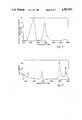
- FIG. 2is the absorption spectrum of a fibre containing ⁇ 30 ppm Nd 3+ ,
- FIG. 3is the fluorescence spectrum of a fibre containing ⁇ 300 ppm Nd 3+ ,
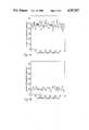
- FIG. 4(a)is the local attenuation of a Nd 3+ -doped single mode fibre
- FIG. 4(b)is the corresponding absorption of a reference fibre
- FIG. 5is an absorption spectrum showing losses due to hydroxyl ion absorption
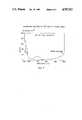
- FIG. 6shows the absorption spectrum of a single-mode fibre co-doped with Tb 3+ and Er 3+ ions in the core region.
- a deposition tubePrior to deposition, a deposition tube is prepared by introducing the required dopant into a dopant carrier chamber 1 where it is purified by heating under a dehydrating atmosphere, e.g. one containing either gaseous chlorine or gaseous fluorine, using a stationary heat source, e.g. burner 2. This step also fuses the dopant material to the chamber wall, preventing particles of the dopant passing down the tube and forming bubbles in the glass subsequently deposited. The inside of the deposition tube 4 is then cleaned by gas-phase etching using fluorine generated by thermally decomposing a fluorine-containing compound, e.g.
- the dopant carrier chamberis heated to a temperature at which the solid impurity dopant either sublimes or becomes a liquid with a partial vapour-pressure of a few millimetres of mercury, which occurs typically at 900° to 1200° C.
- the porous glass layeris then further dried by heating under a dehydrating atmosphere, after which it is fused to form a clear non-porous layer.
- the tubeis then collapsed to form a solid rod and pulled into a fibre.
- a further specific embodiment of the inventionis the fabrication of single- and multi-mode optical fibres doped with, for example, neodymium ions, Nd 3+ , in the core region.
- a fluorine-liberating vapoursuch as Sulphur hexafluoride (SF 6 ).
- the fibre corewas then deposited unfused, whilst heating the dopant carrier chamber as described previously, such that the NdCl 3 vapour produced in the dopant carrier chamber was oxidised to Nd 2 O 3 within the hot-zone.
- the core layerwas subsequently dried under a chlorine atmosphere and sintered before collapsing the tube to a solid rod.
- the fluorescence spectrum of a fibre doped with ⁇ 300 ppm Nd 3+is shown in FIG. 3, where broad fluorescence bands with peak wavelengths of 940, 1080 and 1370 nm can be clearly seen.
- the bandsare shifted to slightly longer wavelengths than the corresponding bands in compound glasses used for conventional lasers.
- Measurements of the 1/e fluorescence lifetime using a 590 nm pump wavelengthgave a figure of 450 ⁇ s for both the 940 nm and 1080 nm transitions.
- the consistency of the dopant incorporation along the fibre lengthhas been resolved by measuring the local attenuation along the fibre length using an OTDR technique.
- the source wavelength of 620 nmis chosen to lie on the tail of the 590 nm absorption band so as to achieve a manageable attenuation.
- the resultsare shown in FIGS. 4(a and b) and indicate good uniformity of dopant incorporation along the length of the fibre, thus indicating the high degree of control in the fabrication process.
- Fibres containing up to 0.25 wt % Er 3+have been fabricated using this technique, which gives losses of less than 40 dB/km in the region between 1 ⁇ m and 1.3 ⁇ m, despite absorption band peaks of >50 dB/m.
- a further specific embodimentconcerns a fibre containing Terbium ions Tb 3+ co-doped with Erbium, Er 3+ , ions in the core region.
- Fibres pulled from such a preformhave exhibited similar absorption characteristics as shown in FIG. 6, in which the large absorptions peak at 486 nm and the broad absorption centred on 725 nm are due to the presence of Tb 3+ ion, whilst the absorptions at 518 and 970 nm are due to the presence of Er 3+ ion.
- the methodmay also be used to incorporate other rare-earth and transition metal ions into optical fibres.
- MCVDmodified chemical vapour deposition process
Landscapes
- Physics & Mathematics (AREA)
- Engineering & Computer Science (AREA)
- Electromagnetism (AREA)
- Chemical & Material Sciences (AREA)
- Optics & Photonics (AREA)
- Plasma & Fusion (AREA)
- General Life Sciences & Earth Sciences (AREA)
- Chemical Kinetics & Catalysis (AREA)
- Materials Engineering (AREA)
- Organic Chemistry (AREA)
- Geochemistry & Mineralogy (AREA)
- Life Sciences & Earth Sciences (AREA)
- General Chemical & Material Sciences (AREA)
- Manufacturing & Machinery (AREA)
- General Physics & Mathematics (AREA)
- Lasers (AREA)
- Glass Compositions (AREA)
- Manufacture, Treatment Of Glass Fibers (AREA)
- Multicomponent Fibers (AREA)
- Led Devices (AREA)
- Optical Communication System (AREA)
- Laser Surgery Devices (AREA)
Abstract
Description
Claims (8)
Applications Claiming Priority (4)
| Application Number | Priority Date | Filing Date | Title |
|---|---|---|---|
| GB858520301AGB8520301D0 (en) | 1985-08-13 | 1985-08-13 | Lasers |
| GB8520300 | 1985-08-13 | ||
| GB8520301 | 1985-08-13 | ||
| GB858520300AGB8520300D0 (en) | 1985-08-13 | 1985-08-13 | Fabrication of optical fibres |
Publications (1)
| Publication Number | Publication Date |
|---|---|
| US4787927Atrue US4787927A (en) | 1988-11-29 |
Family
ID=26289658
Family Applications (2)
| Application Number | Title | Priority Date | Filing Date |
|---|---|---|---|
| US07/064,943Expired - LifetimeUS4787927A (en) | 1985-08-13 | 1986-08-13 | Fabrication of optical fibers |
| US07/326,458Expired - LifetimeUS4955025A (en) | 1985-08-13 | 1989-03-20 | Fibre-optic lasers and amplifiers |
Family Applications After (1)
| Application Number | Title | Priority Date | Filing Date |
|---|---|---|---|
| US07/326,458Expired - LifetimeUS4955025A (en) | 1985-08-13 | 1989-03-20 | Fibre-optic lasers and amplifiers |
Country Status (8)
| Country | Link |
|---|---|
| US (2) | US4787927A (en) |
| EP (2) | EP0272258B1 (en) |
| JP (2) | JP3020459B2 (en) |
| AT (2) | ATE207662T1 (en) |
| AU (2) | AU584739B2 (en) |
| DE (1) | DE3650765T2 (en) |
| GB (4) | GB2199690A (en) |
| WO (2) | WO1987001110A1 (en) |
Cited By (35)
| Publication number | Priority date | Publication date | Assignee | Title |
|---|---|---|---|---|
| US5039199A (en)* | 1989-12-29 | 1991-08-13 | At&T Bell Laboratories | Lightwave transmission system having remotely pumped quasi-distributed amplifying fibers |
| US5059230A (en)* | 1990-01-22 | 1991-10-22 | At&T Bell Laboratories | Fabrication of doped filament optical fibers |
| US5058974A (en)* | 1989-10-06 | 1991-10-22 | At&T Bell Laboratories | Distributed amplification for lightwave transmission system |
| US5236481A (en)* | 1992-02-21 | 1993-08-17 | Corning Incorporated | Method of doping porous glass preforms |
| US5284500A (en)* | 1989-10-31 | 1994-02-08 | Fujitsu Limited | Process for fabricating an optical fiber preform |
| US5356448A (en)* | 1992-05-13 | 1994-10-18 | Alcatel N.V. | Method of making a preform for an optical fiber |
| EP0692722A2 (en) | 1994-07-13 | 1996-01-17 | AT&T Corp. | Optical attenuator |
| US5503650A (en)* | 1992-03-17 | 1996-04-02 | Sumitomo Electric Industries, Ltd. | Method for producing a glass thin film with controlloing an oxide vapor of an additive |
| US5711782A (en)* | 1989-10-31 | 1998-01-27 | Fujitsu Limited | Process for fabricating an optical fiber preform |
| US5961682A (en)* | 1995-07-12 | 1999-10-05 | Samsung Electronics Co., Ltd. | Method of fabricating optical fiber doped with rare earth element using volatile complex |
| US6145345A (en)* | 1998-06-05 | 2000-11-14 | Lucent Technologies Inc. | Modified chemical vapor deposition using independently controlled thermal sources |
| US6217204B1 (en)* | 1997-01-08 | 2001-04-17 | Fujitsu Limited | Optical fiber assembly and light amplification coupler having rare earth doped light amplification medium and related method of making |
| DE4209004C2 (en)* | 1992-03-20 | 2001-06-21 | Sel Alcatel Ag | Method and device for producing an optical fiber preform |
| US20020157423A1 (en)* | 2001-04-30 | 2002-10-31 | Intelcore Technologies, Inc. | Hybrid manufacturing process for optical fibers |
| US6474106B1 (en)* | 1999-11-30 | 2002-11-05 | Corning Incorporated | Rare earth and alumina-doped optical fiber preform process |
| US6490889B1 (en)* | 1998-06-30 | 2002-12-10 | Jds Uniphase Corporation | Method of forming a glass preform |
| US6498888B1 (en) | 1998-04-22 | 2002-12-24 | Institut National D'optique | High-attenuation fiber with cladding mode suppression for all-fiber optical attenuator |
| US20030134359A1 (en)* | 2000-06-05 | 2003-07-17 | Genentech, Inc. | Secreted and transmembrane polypeptides and nucleic acids encoding the same |
| US6602558B1 (en)* | 1998-08-07 | 2003-08-05 | Toyota Jidosha Kabushiki Kaisha | Non-linear optical silica thin film manufacturing method and non-linear optical silica element |
| USRE38298E1 (en)* | 1989-08-11 | 2003-11-04 | Corning O.T.I Spa | Double-core active fiber optical amplifier having a wide-band signal wavelength |
| US20030217569A1 (en)* | 2002-05-23 | 2003-11-27 | Sigel George H. | Fiber optic cable and process for manufacturing |
| US20040036957A1 (en)* | 1997-03-21 | 2004-02-26 | Imra America, Inc. | Microchip-Yb fiber hybrid optical amplifier for micro-machining and marking |
| US20050008044A1 (en)* | 1998-11-25 | 2005-01-13 | Fermann Martin E. | Mode-locked multi-mode fiber laser pulse source |
| US20050018714A1 (en)* | 2003-07-25 | 2005-01-27 | Fermann Martin E. | Polarization maintaining dispersion controlled fiber laser source of ultrashort pulses |
| US20050069638A1 (en)* | 2003-09-29 | 2005-03-31 | Liekki Oy | System for forming a gas flow of reactants for a doped glass material |
| US20050226286A1 (en)* | 2004-03-31 | 2005-10-13 | Imra America, Inc. | Modular fiber-based chirped pulse amplification system |
| US20050276555A1 (en)* | 2004-06-02 | 2005-12-15 | Tetsuya Haruna | Glass-body-producing method and optical glass body and optical fiber |
| US20060132904A1 (en)* | 1998-07-16 | 2006-06-22 | Imra America, Inc. | Microchip-Yb fiber hybrid optical amplifier for micro-machining and marking |
| DE102007033086A1 (en)* | 2007-07-15 | 2009-01-29 | Heraeus Quarzglas Gmbh & Co. Kg | Method for producing an optical component with longitudinal bores, and microstructured optical fiber |
| US7656578B2 (en) | 1997-03-21 | 2010-02-02 | Imra America, Inc. | Microchip-Yb fiber hybrid optical amplifier for micro-machining and marking |
| US20110179827A1 (en)* | 2008-10-06 | 2011-07-28 | Asahi Glass Company, Limited | Process for production of synthetic quartz glass |
| US8208196B2 (en) | 2003-07-25 | 2012-06-26 | Imra America, Inc. | Pulsed laser sources |
| EP2763247A2 (en) | 2006-05-11 | 2014-08-06 | SPI Lasers UK Limited | Apparatus for providing optical radiation |
| US9071037B2 (en) | 2004-03-31 | 2015-06-30 | Imra America, Inc. | High power short pulse fiber laser |
| US20180370841A1 (en)* | 2017-06-21 | 2018-12-27 | Fujikura Ltd. | Method for manufacturing optical fiber preform, method for manufacturing optical fiber, and method for doping silica glass |
Families Citing this family (62)
| Publication number | Priority date | Publication date | Assignee | Title |
|---|---|---|---|---|
| IT1191998B (en)* | 1986-04-10 | 1988-03-31 | Cselt Centro Studi Lab Telecom | PROCEDURE AND EQUIPMENT FOR THE PRODUCTION OF PREFORMS FOR OPTICAL FIBERS OPERATING IN THE MIDDLE INFRARED SPECTRAL REGION |
| US4936650A (en)* | 1986-04-24 | 1990-06-26 | British Telecommunications Public Limited Company | Optical wave guides |
| GB8610053D0 (en)* | 1986-04-24 | 1986-05-29 | British Telecomm | Glass fibre |
| GB8613192D0 (en)* | 1986-05-30 | 1986-07-02 | British Telecomm | Optical resonating device |
| CA1294802C (en)* | 1986-06-04 | 1992-01-28 | Benjamin J. Ainslie | Optical waveguides and their manufacture |
| GB8622745D0 (en)* | 1986-09-22 | 1986-10-29 | Plessey Co Plc | Bistable optical device |
| GB2210613B (en)* | 1987-09-25 | 1991-08-14 | Gen Electric Co Plc | Manufacture of optical fibre preforms |
| FR2621909B1 (en)* | 1987-10-16 | 1990-01-19 | Comp Generale Electricite | |
| GB8724736D0 (en)* | 1987-10-22 | 1987-11-25 | British Telecomm | Optical fibre |
| GB8808762D0 (en)* | 1988-04-13 | 1988-05-18 | Southampton University | Glass laser operating in visible region |
| US5282079A (en)* | 1988-06-10 | 1994-01-25 | Pirelli General Plc | Optical fibre amplifier |
| IT1219404B (en)* | 1988-06-27 | 1990-05-11 | Sip | PROCEDURE AND EQUIPMENT FOR THE MANUFACTURE OF FIBER OPTICS IN SILICA |
| GB2220789B (en)* | 1988-07-15 | 1992-08-26 | Stc Plc | Low coherence optical source |
| FR2638854B1 (en)* | 1988-11-10 | 1992-09-04 | Comp Generale Electricite | DOPED FIBER OPTIC LASER AMPLIFIER |
| GB2226309A (en)* | 1988-12-01 | 1990-06-27 | Stc Plc | Optical fibre manufacture |
| JPH0758377B2 (en)* | 1988-12-12 | 1995-06-21 | 日本電信電話株式会社 | Optical fiber type optical amplifier |
| GB2236895A (en)* | 1989-07-13 | 1991-04-17 | British Telecomm | Optical communications system |
| GB2236426B (en)* | 1989-09-20 | 1994-01-26 | Stc Plc | Laser source |
| EP0454865B1 (en)* | 1989-11-20 | 1996-05-01 | Fujitsu Limited | Optical amplifier |
| AU636961B2 (en)* | 1990-02-20 | 1993-05-13 | British Telecommunications Public Limited Company | Tunable optical filters |
| GB2257803B (en)* | 1990-02-20 | 1993-10-06 | British Telecomm | Tunable optical filters |
| GB9007912D0 (en)* | 1990-04-06 | 1990-06-06 | British Telecomm | A method of forming a refractive index grating in an optical waveguide |
| FR2661783A1 (en)* | 1990-05-02 | 1991-11-08 | Monerie Michel | OPTICAL DEVICE FOR THE EMISSION AND AMPLIFICATION OF LIGHT IN THE ACTIVE 1260-1234NM RANGE CONTAINING PRASEODYM. |
| US5260823A (en)* | 1990-05-21 | 1993-11-09 | University Of Southampton | Erbium-doped fibre amplifier with shaped spectral gain |
| GB2245096A (en)* | 1990-06-01 | 1991-12-18 | Gen Electric Co Plc | Semiconductor laser pump source |
| US5084880A (en)* | 1990-07-02 | 1992-01-28 | The United States Of America As Represented By The Sectretary Of The Navy | Erbium-doped fluorozirconate fiber laser pumped by a diode laser source |
| JPH0777279B2 (en)* | 1990-07-27 | 1995-08-16 | パイオニア株式会社 | Optical pulse generator |
| JP2888616B2 (en)* | 1990-08-08 | 1999-05-10 | 住友電気工業株式会社 | Optical amplifier and optical oscillator |
| GB2249660B (en)* | 1990-11-09 | 1994-07-06 | Stc Plc | Amplified optical fibre systems |
| US5151908A (en)* | 1990-11-20 | 1992-09-29 | General Instrument Corporation | Laser with longitudinal mode selection |
| US5067789A (en)* | 1991-02-14 | 1991-11-26 | Corning Incorporated | Fiber optic coupling filter and amplifier |
| US5179603A (en)* | 1991-03-18 | 1993-01-12 | Corning Incorporated | Optical fiber amplifier and coupler |
| US5187759A (en)* | 1991-11-07 | 1993-02-16 | At&T Bell Laboratories | High gain multi-mode optical amplifier |
| US5504771A (en)* | 1992-11-03 | 1996-04-02 | California Institute Of Technology | Fiber-optic ring laser |
| DE4306933A1 (en)* | 1993-03-05 | 1994-09-08 | Sel Alcatel Ag | Method of making a reinforcement optical fiber preform |
| US5689519A (en) | 1993-12-20 | 1997-11-18 | Imra America, Inc. | Environmentally stable passively modelocked fiber laser pulse source |
| US6137812A (en)* | 1994-02-24 | 2000-10-24 | Micron Optics, Inc. | Multiple cavity fiber fabry-perot lasers |
| US5425039A (en)* | 1994-02-24 | 1995-06-13 | Micron Optics, Inc. | Single-frequency fiber Fabry-Perot micro lasers |
| US5521999A (en)* | 1994-03-17 | 1996-05-28 | Eastman Kodak Company | Optical system for a laser printer |
| US5778016A (en) | 1994-04-01 | 1998-07-07 | Imra America, Inc. | Scanning temporal ultrafast delay methods and apparatuses therefor |
| US5450427A (en)* | 1994-10-21 | 1995-09-12 | Imra America, Inc. | Technique for the generation of optical pulses in modelocked lasers by dispersive control of the oscillation pulse width |
| DE4447356A1 (en)* | 1994-12-20 | 1996-06-27 | Max Born Inst Fuer Nichtlinear | Optical fibre laser beam generator for esp. optical telecommunications system |
| US5594748A (en)* | 1995-08-10 | 1997-01-14 | Telephone Information Systems, Inc. | Method and apparatus for predicting semiconductor laser failure |
| AUPN694795A0 (en) | 1995-12-01 | 1996-01-04 | University Of Sydney, The | Distributed feedback ring laser |
| KR100450323B1 (en)* | 1997-11-04 | 2005-01-17 | 삼성전자주식회사 | Glass composition for laser amplification comprising ge-ga-s-based glass host containing earth metal-based active material containing pr¬3+ ion, and transition metal ion |
| US6016371A (en)* | 1997-12-19 | 2000-01-18 | Trw Inc. | Optical RF signal processing |
| JPH11242130A (en) | 1998-02-26 | 1999-09-07 | Nec Corp | Light source module incorporating synthesizing function, optical amplifier using this module, and bidirectional optical transmission equipment |
| US6148011A (en)* | 1998-05-01 | 2000-11-14 | Institut National D'optique | Wavelength sliced self-seeded pulsed laser |
| JP2000091678A (en)* | 1998-09-11 | 2000-03-31 | Nec Corp | Fiber laser irradiation device |
| US6407855B1 (en) | 1999-10-29 | 2002-06-18 | Sdl, Inc. | Multiple wavelength optical sources |
| US6353497B1 (en) | 2000-03-03 | 2002-03-05 | Optical Coating Laboratory, Inc. | Integrated modular optical amplifier |
| KR20010111163A (en) | 2000-06-08 | 2001-12-17 | 오길록 | 1530㎚-band pumped l-band erbium doped fiber amplifier |
| US6947208B2 (en)* | 2002-01-25 | 2005-09-20 | John Ballato | Optical fiber amplifier with fully integrated pump source |
| KR100521958B1 (en)* | 2002-09-18 | 2005-10-14 | 엘에스전선 주식회사 | method and apparatus for fabricating of optical fiber preform with double torch in MCVD |
| EP1558955A4 (en)* | 2002-10-15 | 2006-04-19 | Micron Optics Inc | Waferless fiber fabry-perot filters |
| EP1583989A4 (en)* | 2002-12-20 | 2006-07-05 | Micron Optics Inc | Temperature compensated ferrule holder for a fiber fabry-perot filter |
| DE10302031A1 (en)* | 2003-01-21 | 2004-09-23 | Evotec Oai Ag | Fiber laser |
| US7120174B2 (en)* | 2004-06-14 | 2006-10-10 | Jds Uniphase Corporation | Pulsed laser apparatus and method |
| US7375701B2 (en)* | 2004-07-01 | 2008-05-20 | Carestream Health, Inc. | Scanless virtual retinal display system |
| US7333263B2 (en)* | 2005-01-24 | 2008-02-19 | National Sun Yat-Sen University | Transition metal doped fiber amplifier |
| CN102052278B (en)* | 2010-11-09 | 2013-03-13 | 杭州电子科技大学 | Micropump driving device based on photonic crystal fiber |
| JP6084260B2 (en)* | 2015-08-03 | 2017-02-22 | 小林製薬株式会社 | Chemical volatilizer |
Citations (5)
| Publication number | Priority date | Publication date | Assignee | Title |
|---|---|---|---|---|
| US3971645A (en)* | 1975-09-12 | 1976-07-27 | Bell Telephone Laboratories, Incorporated | Method of making compound-glass optical waveguides fabricated by a metal evaporation technique |
| US4067709A (en)* | 1976-05-03 | 1978-01-10 | Stanton Austin N | Optical transmission line |
| US4188089A (en)* | 1976-10-27 | 1980-02-12 | Jenaer Glaswerk Schott & Gen. | Optical fibers having high infrared transmittancy |
| US4529427A (en)* | 1977-05-19 | 1985-07-16 | At&T Bell Laboratories | Method for making low-loss optical waveguides on an industrial scale |
| US4597787A (en)* | 1984-11-13 | 1986-07-01 | Ispra Fibroptics Industries Herzlia Ltd. | Manufacture of optical fibre preforms |
Family Cites Families (22)
| Publication number | Priority date | Publication date | Assignee | Title |
|---|---|---|---|---|
| NL137422C (en)* | 1961-10-27 | |||
| US3729690A (en)* | 1961-10-27 | 1973-04-24 | American Optical Corp | Means for producing and amplifying optical energy |
| US4044315A (en)* | 1962-01-16 | 1977-08-23 | American Optical Corporation | Means for producing and amplifying optical energy |
| US3626312A (en)* | 1968-10-04 | 1971-12-07 | American Optical Corp | Laser preamplifier |
| US3599106A (en)* | 1968-11-06 | 1971-08-10 | American Optical Corp | High intensity-high coherence laser system |
| US3705992A (en)* | 1971-12-13 | 1972-12-12 | Bell Telephone Labor Inc | Broadband tunable raman-effect devices in optical fibers |
| JPS579041B2 (en)* | 1974-11-29 | 1982-02-19 | ||
| US4063106A (en)* | 1977-04-25 | 1977-12-13 | Bell Telephone Laboratories, Incorporated | Optical fiber Raman oscillator |
| US4515431A (en)* | 1982-08-11 | 1985-05-07 | The Board Of Trustees Of The Leland Stanford Junior University | Fiber optic amplifier |
| US4546476A (en)* | 1982-12-10 | 1985-10-08 | The Board Of Trustees Of The Leland Stanford Junior University | Fiber optic amplifier |
| US4554510A (en)* | 1983-09-12 | 1985-11-19 | The Board Of Trustees Of Leland Stanford Junior University | Switching fiber optic amplifier |
| US4553238A (en)* | 1983-09-30 | 1985-11-12 | The Board Of Trustees Of The Leland Stanford University | Fiber optic amplifier |
| US4674830A (en)* | 1983-11-25 | 1987-06-23 | The Board Of Trustees Of The Leland Stanford Junior University | Fiber optic amplifier |
| US4723824A (en)* | 1983-11-25 | 1988-02-09 | The Board Of Trustees Of The Leland Stanford Junior University | Fiber optic amplifier |
| GB2151868B (en)* | 1983-12-16 | 1986-12-17 | Standard Telephones Cables Ltd | Optical amplifiers |
| DE3584091D1 (en)* | 1984-10-01 | 1991-10-17 | Polaroid Corp | AMPLIFIER FOR OPTICAL WAVE GUIDE AND LASER. |
| US4637025A (en)* | 1984-10-22 | 1987-01-13 | Polaroid Corporation | Super radiant light source |
| US4756003A (en)* | 1985-05-01 | 1988-07-05 | Spectra-Physics, Inc. | Laser diode pumped solid state laser |
| US4680767A (en)* | 1985-07-01 | 1987-07-14 | Polaroid Corporation | Optical fiber laser |
| US4712075A (en)* | 1985-11-27 | 1987-12-08 | Polaroid Corporation | Optical amplifier |
| US4731787A (en)* | 1986-08-15 | 1988-03-15 | Board Of Trustees, Stanford University | Monolithic phasematched laser harmonic generator |
| JPH075477A (en)* | 1993-06-17 | 1995-01-10 | Hitachi Ltd | Liquid crystal display |
- 1986
- 1986-08-13GBGB08801958Apatent/GB2199690A/ennot_activeWithdrawn
- 1986-08-13GBGB8619697Apatent/GB2180832B/ennot_activeExpired
- 1986-08-13GBGB8801960Apatent/GB2199029B/ennot_activeExpired - Lifetime
- 1986-08-13AUAU62204/86Apatent/AU584739B2/ennot_activeExpired
- 1986-08-13EPEP86904883Apatent/EP0272258B1/ennot_activeExpired - Lifetime
- 1986-08-13AUAU62206/86Apatent/AU607895B2/ennot_activeExpired
- 1986-08-13GBGB8619698Apatent/GB2180392B/ennot_activeExpired
- 1986-08-13DEDE3650765Tpatent/DE3650765T2/ennot_activeExpired - Lifetime
- 1986-08-13WOPCT/GB1986/000484patent/WO1987001110A1/enactiveIP Right Grant
- 1986-08-13USUS07/064,943patent/US4787927A/ennot_activeExpired - Lifetime
- 1986-08-13WOPCT/GB1986/000485patent/WO1987001246A1/ennot_activeApplication Discontinuation
- 1986-08-13EPEP86904884Apatent/EP0269624B1/ennot_activeRevoked
- 1986-08-13ATAT86904884Tpatent/ATE207662T1/ennot_activeIP Right Cessation
- 1986-08-13ATAT86904883Tpatent/ATE81114T1/ennot_activeIP Right Cessation
- 1989
- 1989-03-20USUS07/326,458patent/US4955025A/ennot_activeExpired - Lifetime
- 1997
- 1997-03-24JPJP9087224Apatent/JP3020459B2/ennot_activeExpired - Lifetime
- 1997-03-24JPJP9087223Apatent/JPH1032361A/enactivePending
Patent Citations (5)
| Publication number | Priority date | Publication date | Assignee | Title |
|---|---|---|---|---|
| US3971645A (en)* | 1975-09-12 | 1976-07-27 | Bell Telephone Laboratories, Incorporated | Method of making compound-glass optical waveguides fabricated by a metal evaporation technique |
| US4067709A (en)* | 1976-05-03 | 1978-01-10 | Stanton Austin N | Optical transmission line |
| US4188089A (en)* | 1976-10-27 | 1980-02-12 | Jenaer Glaswerk Schott & Gen. | Optical fibers having high infrared transmittancy |
| US4529427A (en)* | 1977-05-19 | 1985-07-16 | At&T Bell Laboratories | Method for making low-loss optical waveguides on an industrial scale |
| US4597787A (en)* | 1984-11-13 | 1986-07-01 | Ispra Fibroptics Industries Herzlia Ltd. | Manufacture of optical fibre preforms |
Non-Patent Citations (4)
| Title |
|---|
| Electronics Letters, vol. 21, No. 17, 15 Aug. 1985 (GB) S. B. Poole et al., "Fabrication of Low-Loss Optical Fibers Containing Rare-Earth Ion", pp. 737,738. |
| Electronics Letters, vol. 21, No. 17, 15 Aug. 1985 (GB) S. B. Poole et al., Fabrication of Low Loss Optical Fibers Containing Rare Earth Ion , pp. 737,738.* |
| Japanese Journal of Applied Physics, vol. 22, No. 8, Aug. 1983, part 2, (Tokyo, JP) Seiko Mitachi: "Reduction of Impurities in Fluoride Glass Optical Fiber", pp. L537-L538. |
| Japanese Journal of Applied Physics, vol. 22, No. 8, Aug. 1983, part 2, (Tokyo, JP) Seiko Mitachi: Reduction of Impurities in Fluoride Glass Optical Fiber , pp. L537 L538.* |
Cited By (69)
| Publication number | Priority date | Publication date | Assignee | Title |
|---|---|---|---|---|
| USRE38298E1 (en)* | 1989-08-11 | 2003-11-04 | Corning O.T.I Spa | Double-core active fiber optical amplifier having a wide-band signal wavelength |
| US5058974A (en)* | 1989-10-06 | 1991-10-22 | At&T Bell Laboratories | Distributed amplification for lightwave transmission system |
| EP0421675B1 (en)* | 1989-10-06 | 1996-09-11 | AT&T Corp. | Distributed amplification for lightwave transmission system |
| US5284500A (en)* | 1989-10-31 | 1994-02-08 | Fujitsu Limited | Process for fabricating an optical fiber preform |
| US5711782A (en)* | 1989-10-31 | 1998-01-27 | Fujitsu Limited | Process for fabricating an optical fiber preform |
| US5039199A (en)* | 1989-12-29 | 1991-08-13 | At&T Bell Laboratories | Lightwave transmission system having remotely pumped quasi-distributed amplifying fibers |
| US5059230A (en)* | 1990-01-22 | 1991-10-22 | At&T Bell Laboratories | Fabrication of doped filament optical fibers |
| US5236481A (en)* | 1992-02-21 | 1993-08-17 | Corning Incorporated | Method of doping porous glass preforms |
| US5503650A (en)* | 1992-03-17 | 1996-04-02 | Sumitomo Electric Industries, Ltd. | Method for producing a glass thin film with controlloing an oxide vapor of an additive |
| US5660611A (en)* | 1992-03-17 | 1997-08-26 | Sumitomo Electric Industries, Ltd. | Method for producing glass thin film |
| DE4209004C2 (en)* | 1992-03-20 | 2001-06-21 | Sel Alcatel Ag | Method and device for producing an optical fiber preform |
| US5356448A (en)* | 1992-05-13 | 1994-10-18 | Alcatel N.V. | Method of making a preform for an optical fiber |
| EP0692722A2 (en) | 1994-07-13 | 1996-01-17 | AT&T Corp. | Optical attenuator |
| US5572618A (en)* | 1994-07-13 | 1996-11-05 | Lucent Technologies Inc. | Optical attenuator |
| US5961682A (en)* | 1995-07-12 | 1999-10-05 | Samsung Electronics Co., Ltd. | Method of fabricating optical fiber doped with rare earth element using volatile complex |
| US6217204B1 (en)* | 1997-01-08 | 2001-04-17 | Fujitsu Limited | Optical fiber assembly and light amplification coupler having rare earth doped light amplification medium and related method of making |
| US20080285117A1 (en)* | 1997-03-21 | 2008-11-20 | Imra America, Inc. | MICROCHIP-Yb FIBER HYBRID OPTICAL AMPLIFIER FOR MICRO-MACHINING AND MARKING |
| US7656578B2 (en) | 1997-03-21 | 2010-02-02 | Imra America, Inc. | Microchip-Yb fiber hybrid optical amplifier for micro-machining and marking |
| US20100110537A1 (en)* | 1997-03-21 | 2010-05-06 | Imra America, Inc. | MICROCHIP-Yb FIBER HYBRID OPTICAL AMPLIFIER FOR MICRO-MACHINING AND MARKING |
| US7995270B2 (en) | 1997-03-21 | 2011-08-09 | Imra America, Inc. | Microchip—Yb fiber hybrid optical amplifier for micro-machining and marking |
| US7492508B2 (en) | 1997-03-21 | 2009-02-17 | Aisin Seiki Co., Ltd. | Microchip—Yb fiber hybrid optical amplifier for micro-machining and marking |
| US20040036957A1 (en)* | 1997-03-21 | 2004-02-26 | Imra America, Inc. | Microchip-Yb fiber hybrid optical amplifier for micro-machining and marking |
| US6498888B1 (en) | 1998-04-22 | 2002-12-24 | Institut National D'optique | High-attenuation fiber with cladding mode suppression for all-fiber optical attenuator |
| US6145345A (en)* | 1998-06-05 | 2000-11-14 | Lucent Technologies Inc. | Modified chemical vapor deposition using independently controlled thermal sources |
| US6532774B2 (en) | 1998-06-30 | 2003-03-18 | Jds Uniphase Corporation | Method of providing a high level of rare earth concentrations in glass fiber preforms |
| US6523369B1 (en) | 1998-06-30 | 2003-02-25 | Jds Uniphase Corporation | Method of forming an optical fiber |
| US6604388B1 (en) | 1998-06-30 | 2003-08-12 | Jds Uniphase Corporation | Solid state glass constituent delivery system |
| US6490889B1 (en)* | 1998-06-30 | 2002-12-10 | Jds Uniphase Corporation | Method of forming a glass preform |
| US6510710B1 (en) | 1998-06-30 | 2003-01-28 | Jds Uniphase Corporation | Multi-tube delivery system |
| US7576909B2 (en) | 1998-07-16 | 2009-08-18 | Imra America, Inc. | Multimode amplifier for amplifying single mode light |
| US7190511B2 (en) | 1998-07-16 | 2007-03-13 | Imra America | Fiber laser system with increased optical damage threshold |
| US20060132904A1 (en)* | 1998-07-16 | 2006-06-22 | Imra America, Inc. | Microchip-Yb fiber hybrid optical amplifier for micro-machining and marking |
| US6602558B1 (en)* | 1998-08-07 | 2003-08-05 | Toyota Jidosha Kabushiki Kaisha | Non-linear optical silica thin film manufacturing method and non-linear optical silica element |
| US20050008044A1 (en)* | 1998-11-25 | 2005-01-13 | Fermann Martin E. | Mode-locked multi-mode fiber laser pulse source |
| US8761211B2 (en)* | 1998-11-25 | 2014-06-24 | Imra America, Inc. | Multi-mode fiber amplifier |
| US8873593B2 (en)* | 1998-11-25 | 2014-10-28 | Imra America, Inc. | Mode-locked multi-mode fiber laser pulse source |
| US9153929B2 (en) | 1998-11-25 | 2015-10-06 | Imra America, Inc. | Mode-locked multi-mode fiber laser pulse source |
| US9450371B2 (en) | 1998-11-25 | 2016-09-20 | Imra America, Inc. | Mode-locked multi-mode fiber laser pulse source |
| US9570880B2 (en) | 1998-11-25 | 2017-02-14 | Imra America, Inc. | Multi-mode fiber amplifier |
| US9595802B2 (en) | 1998-11-25 | 2017-03-14 | Imra America, Inc. | Multi-mode fiber amplifier |
| US6474106B1 (en)* | 1999-11-30 | 2002-11-05 | Corning Incorporated | Rare earth and alumina-doped optical fiber preform process |
| US20030134359A1 (en)* | 2000-06-05 | 2003-07-17 | Genentech, Inc. | Secreted and transmembrane polypeptides and nucleic acids encoding the same |
| US7003984B2 (en) | 2001-04-30 | 2006-02-28 | Verrillon, Inc. | Hybrid manufacturing process for optical fibers |
| US20020157423A1 (en)* | 2001-04-30 | 2002-10-31 | Intelcore Technologies, Inc. | Hybrid manufacturing process for optical fibers |
| US20050284183A1 (en)* | 2002-05-23 | 2005-12-29 | Sigel George H Jr | Fiber optic cable and process for manufacturing |
| US7181116B2 (en) | 2002-05-23 | 2007-02-20 | Rutgers, The State University Of New Jersey | Fiber optic cable and process for manufacturing |
| US20030217569A1 (en)* | 2002-05-23 | 2003-11-27 | Sigel George H. | Fiber optic cable and process for manufacturing |
| US6970630B2 (en) | 2002-05-23 | 2005-11-29 | Rutgers, The State University Of New Jersey | Fiber optic cable and process for manufacturing |
| US8599473B2 (en) | 2003-07-25 | 2013-12-03 | Imra America, Inc. | Pulsed laser sources |
| US9653868B2 (en) | 2003-07-25 | 2017-05-16 | Imra America, Inc. | Pulsed laser sources |
| US20050018714A1 (en)* | 2003-07-25 | 2005-01-27 | Fermann Martin E. | Polarization maintaining dispersion controlled fiber laser source of ultrashort pulses |
| US9401579B2 (en) | 2003-07-25 | 2016-07-26 | Imra America, Inc. | Pulsed laser sources |
| US7088756B2 (en) | 2003-07-25 | 2006-08-08 | Imra America, Inc. | Polarization maintaining dispersion controlled fiber laser source of ultrashort pulses |
| US8208196B2 (en) | 2003-07-25 | 2012-06-26 | Imra America, Inc. | Pulsed laser sources |
| US8456735B2 (en) | 2003-07-25 | 2013-06-04 | Imra America, Inc. | Pulsed laser sources |
| US20050069638A1 (en)* | 2003-09-29 | 2005-03-31 | Liekki Oy | System for forming a gas flow of reactants for a doped glass material |
| US9640940B2 (en) | 2004-03-31 | 2017-05-02 | Imra America, Inc. | High power short pulse fiber laser |
| US8873594B2 (en) | 2004-03-31 | 2014-10-28 | Imra America, Inc. | Modular fiber-based chirped pulse amplification system |
| US9071037B2 (en) | 2004-03-31 | 2015-06-30 | Imra America, Inc. | High power short pulse fiber laser |
| US20050226286A1 (en)* | 2004-03-31 | 2005-10-13 | Imra America, Inc. | Modular fiber-based chirped pulse amplification system |
| US7711013B2 (en) | 2004-03-31 | 2010-05-04 | Imra America, Inc. | Modular fiber-based chirped pulse amplification system |
| US20100188736A1 (en)* | 2004-03-31 | 2010-07-29 | Imra America, Inc. | Modular fiber-based chirped pulse amplification system |
| US20050276555A1 (en)* | 2004-06-02 | 2005-12-15 | Tetsuya Haruna | Glass-body-producing method and optical glass body and optical fiber |
| US7130513B2 (en)* | 2004-06-02 | 2006-10-31 | Sumitomo Electric Industries, Ltd. | Glass-body-producing method and optical glass body and optical fiber |
| EP2763247A2 (en) | 2006-05-11 | 2014-08-06 | SPI Lasers UK Limited | Apparatus for providing optical radiation |
| DE102007033086A1 (en)* | 2007-07-15 | 2009-01-29 | Heraeus Quarzglas Gmbh & Co. Kg | Method for producing an optical component with longitudinal bores, and microstructured optical fiber |
| US8240172B2 (en)* | 2008-10-06 | 2012-08-14 | Asahi Glass Company, Limited | Process for production of synthetic quartz glass |
| US20110179827A1 (en)* | 2008-10-06 | 2011-07-28 | Asahi Glass Company, Limited | Process for production of synthetic quartz glass |
| US20180370841A1 (en)* | 2017-06-21 | 2018-12-27 | Fujikura Ltd. | Method for manufacturing optical fiber preform, method for manufacturing optical fiber, and method for doping silica glass |
Also Published As
| Publication number | Publication date |
|---|---|
| ATE81114T1 (en) | 1992-10-15 |
| AU584739B2 (en) | 1989-06-01 |
| GB8619698D0 (en) | 1986-09-24 |
| EP0269624B1 (en) | 2001-10-24 |
| DE3650765D1 (en) | 2002-05-08 |
| WO1987001110A1 (en) | 1987-02-26 |
| GB2199029B (en) | 1990-09-05 |
| JP3020459B2 (en) | 2000-03-15 |
| GB2180392B (en) | 1989-10-11 |
| GB8619697D0 (en) | 1986-09-24 |
| GB2180392A (en) | 1987-03-25 |
| AU6220686A (en) | 1987-03-10 |
| AU6220486A (en) | 1987-03-10 |
| WO1987001246A1 (en) | 1987-02-26 |
| GB2199690A (en) | 1988-07-13 |
| EP0272258B1 (en) | 1992-09-30 |
| JPH1032547A (en) | 1998-02-03 |
| GB2180832A (en) | 1987-04-08 |
| US4955025A (en) | 1990-09-04 |
| AU607895B2 (en) | 1991-03-21 |
| DE3650765T2 (en) | 2004-01-29 |
| EP0269624A1 (en) | 1988-06-08 |
| GB8801960D0 (en) | 1988-02-24 |
| EP0272258A1 (en) | 1988-06-29 |
| JPH1032361A (en) | 1998-02-03 |
| GB2180832B (en) | 1989-07-26 |
| GB8801958D0 (en) | 1988-03-16 |
| ATE207662T1 (en) | 2001-11-15 |
| GB2199029A (en) | 1988-06-29 |
Similar Documents
| Publication | Publication Date | Title |
|---|---|---|
| US4787927A (en) | Fabrication of optical fibers | |
| US4923279A (en) | Optical fibre with fluorescent additive | |
| Poole et al. | Fabrication of low-loss optical fibres containing rare-earth ions | |
| MacChesney et al. | Materials development of optical fiber | |
| EP0044712B1 (en) | Improvements in and relating to glass fibres for optical communication | |
| HK113197A (en) | Wave-guiding structure with lasing properties | |
| US4335934A (en) | Single mode fibre and method of making | |
| KR100433909B1 (en) | Amplifying optical fiber and method for fabricating the same | |
| US9139467B2 (en) | Low brillouin scattering optical fibers and formation methods thereof | |
| Bubnov et al. | Fabrication and investigation of single-mode highly phosphorus-doped fibers for Raman lasers | |
| US8494013B2 (en) | Photodarkening resistant optical fibers and fiber lasers incorporating the same | |
| Kanamori | Transmission loss of optical fibers; achievements in half a century | |
| US7440672B2 (en) | Optical fiber for optical amplifier and process for manufacturing thereof | |
| Kasik et al. | Glass materials for optical fibers | |
| JP2792646B2 (en) | Manufacture of optical fiber | |
| AU2002249558B2 (en) | A method of fabricating rare earth doped optical fibre | |
| GB2046239A (en) | Optical fibres | |
| DE3686891T2 (en) | MANUFACTURE OF OPTICAL FIBERS. | |
| Ackler et al. | Opticical Silica Fibers | |
| CA1171703A (en) | Glass fibres for optical communications | |
| Goel | Development of “core-suction” technique for fabrication of highly doped fibers for optical amplification and characterization of optical fibers for Raman amplification | |
| Thambiratnam | Zirconia-Yttria-Alumino Silicate Glass-Based Erbium-Doped Fibres as a Medium for Q-Switched and Mode-Locked Pulse Generation | |
| Hua et al. | The Fabrication And Optical Properties Of Neodymium And Erbium Doped Silica-Based Fibres | |
| Cole | Optimization of thullium (3+) in silica for use as active fiber devices | |
| Townsend et al. | Optical fibre amplifiers |
Legal Events
| Date | Code | Title | Description |
|---|---|---|---|
| AS | Assignment | Owner name:NATIONAL RESEARCH DEVELOPMENT CORPORATION, 101 NEW Free format text:ASSIGNMENT OF ASSIGNORS INTEREST.;ASSIGNORS:MEARS, ROBERT J.;REEKIE, LAURENCE;POOLE, SIMON B.;AND OTHERS;REEL/FRAME:004946/0724 Effective date:19880825 Owner name:NATIONAL RESEARCH DEVELOPMENT CORPORATION, A BRITI Free format text:ASSIGNMENT OF ASSIGNORS INTEREST;ASSIGNORS:MEARS, ROBERT J.;REEKIE, LAURENCE;POOLE, SIMON B.;AND OTHERS;REEL/FRAME:004946/0724 Effective date:19880825 | |
| STCF | Information on status: patent grant | Free format text:PATENTED CASE | |
| FEPP | Fee payment procedure | Free format text:PAYOR NUMBER ASSIGNED (ORIGINAL EVENT CODE: ASPN); ENTITY STATUS OF PATENT OWNER: LARGE ENTITY | |
| FPAY | Fee payment | Year of fee payment:4 | |
| AS | Assignment | Owner name:BRITISH TECHNOLOGY GROUP LIMITED, ENGLAND Free format text:ASSIGNMENT OF ASSIGNORS INTEREST.;ASSIGNOR:NATIONAL RESEARCH DEVELOPMENT CORPORATION;REEL/FRAME:006243/0136 Effective date:19920709 | |
| FEPP | Fee payment procedure | Free format text:PAT HOLDER CLAIMS SMALL ENTITY STATUS - SMALL BUSINESS (ORIGINAL EVENT CODE: SM02); ENTITY STATUS OF PATENT OWNER: LARGE ENTITY | |
| FPAY | Fee payment | Year of fee payment:8 | |
| FEPP | Fee payment procedure | Free format text:PAT HLDR NO LONGER CLAIMS SMALL ENT STAT AS SMALL BUSINESS (ORIGINAL EVENT CODE: LSM2); ENTITY STATUS OF PATENT OWNER: LARGE ENTITY | |
| FEPP | Fee payment procedure | Free format text:PAYER NUMBER DE-ASSIGNED (ORIGINAL EVENT CODE: RMPN); ENTITY STATUS OF PATENT OWNER: LARGE ENTITY Free format text:PAYOR NUMBER ASSIGNED (ORIGINAL EVENT CODE: ASPN); ENTITY STATUS OF PATENT OWNER: LARGE ENTITY | |
| FPAY | Fee payment | Year of fee payment:12 |