US4787406A - Fluid flow control clamp and method for using same - Google Patents
Fluid flow control clamp and method for using sameDownload PDFInfo
- Publication number
- US4787406A US4787406AUS07/098,844US9884487AUS4787406AUS 4787406 AUS4787406 AUS 4787406AUS 9884487 AUS9884487 AUS 9884487AUS 4787406 AUS4787406 AUS 4787406A
- Authority
- US
- United States
- Prior art keywords
- force
- flexible conduit
- resilient pad
- conduit
- clamp
- Prior art date
- Legal status (The legal status is an assumption and is not a legal conclusion. Google has not performed a legal analysis and makes no representation as to the accuracy of the status listed.)
- Expired - Lifetime
Links
Images
Classifications
- A—HUMAN NECESSITIES
- A61—MEDICAL OR VETERINARY SCIENCE; HYGIENE
- A61M—DEVICES FOR INTRODUCING MEDIA INTO, OR ONTO, THE BODY; DEVICES FOR TRANSDUCING BODY MEDIA OR FOR TAKING MEDIA FROM THE BODY; DEVICES FOR PRODUCING OR ENDING SLEEP OR STUPOR
- A61M39/00—Tubes, tube connectors, tube couplings, valves, access sites or the like, specially adapted for medical use
- A61M39/22—Valves or arrangement of valves
- A61M39/28—Clamping means for squeezing flexible tubes, e.g. roller clamps
- A61M39/283—Screw clamps
- Y—GENERAL TAGGING OF NEW TECHNOLOGICAL DEVELOPMENTS; GENERAL TAGGING OF CROSS-SECTIONAL TECHNOLOGIES SPANNING OVER SEVERAL SECTIONS OF THE IPC; TECHNICAL SUBJECTS COVERED BY FORMER USPC CROSS-REFERENCE ART COLLECTIONS [XRACs] AND DIGESTS
- Y10—TECHNICAL SUBJECTS COVERED BY FORMER USPC
- Y10T—TECHNICAL SUBJECTS COVERED BY FORMER US CLASSIFICATION
- Y10T137/00—Fluid handling
- Y10T137/0318—Processes
Definitions
- This inventionrelates to fluid flow control clamp systems and methods for controlling fluid flow. More particularly, the invention relates to such clamp systems and methods useful for controlling fluid flow rates in flexible conduits, e.g., tubing in intravenous systems.
- Intravenous or IV systemsare very important in caring for medical patients. Such systems are extensively used to provide one or more needed fluids, e.g., liquids, directly to the patient's vascular system. Of course, very careful control of the flow rate of any fluid passing into the patient's body is desirable. However, such control has been difficult to obtain.
- fluidse.g., liquids
- Peristaltic pumpsby necessity involve repeated opening and complete occlusion of a fluid containing conduit.
- rollersact to contact the periphery of the conduit with the conduit's periphery opposite the rollers contacting a resilient element. The action of each of these rollers causes the conduit to range from being open to being completely occluded, with no one degree or state of occlusion, e.g., partial occlusion, being maintained for any substantial period of time.
- the rollersact on the conduit to provide the desired pumping action to the fluid in the conduit. With the rollers stopped, no fluid flows through the conduit.
- the inventioninvolves a control clamp including a force means or system structured to be moved to at least partially occlude a flexible conduit. Further, when the force system is activated, the flexible conduit contacts both the force system and a resilient pad means or element which is adapted to aid in at least partially occluding the flexible conduit. This resilient pad element is structured to move in response to the activation of the force system. Moreover, the force system is adapted to maintain the flexible conduit, in which fluid is flowing, in at least one state of partial occlusion.
- the present inventioninvolves a method for controlling the flow rate of a fluid through a flexible conduit.
- This methodcomprises applying a substantially constant force to a first portion of the periphery of the conduit to partially occlude the conduit.
- a second portion of the conduit's periphery substantially opposite the first portionis in contact with a resilient material which moved in response to the initial application of the force.
- the flow rate of a fluid through a flexible conduitis adjusted by a method comprising adjusting the force (magnitude of force) applied to a first portion of the periphery of a flexible conduit, the force acting to partially occlude the conduit.
- a second portion of the periphery of the flexible conduit substantially opposite the first portionis in contact with a resilient material which moves in response to the adjusting of the force.
- the present inventionprovides substantial advantages.
- the clamp apparatusis relatively simple in structure, easy to operate and effective and reliable for its intended purpose.
- the present apparatushas outstanding sensitivity which allows the fluid flow rate in the flexible conduit to be set precisely so that the apparatus can be used to meter fluid or as an off-on valve.
- the movable, resilient pad or materialcauses the force system, in particular a force system having a substantially hemispherical portion which contacts the tubing, to have to travel a greater distance (relative to an unmoving, rigid pad or material) to obtain a given change in the degree of occlusion of the flexible conduit.
- This relatively greater distanceprovides a greater opportunity to precisely set the fluid flow rate in the conduit and, at least in part, provides the present invention with its outstanding control sensitivity.
- the present clamp apparatuspreferably further comprises a substantially rigid base adapted to carry the resilient pad element.
- a clamp housingis preferably included and adapted to hold the force system.
- the substantially rigid baseis a part, preferably an integral part, of the clamp housing.
- the clamp housinginclude a passageway sized and adapted to allow the flexible conduit to pass therethrough.
- both the clamp housing and the force systeminclude mutually mating threads which allow the force system to be moved with respect to the clamp housing, as desired.
- the clamp housingmay be a molded or machined piece, e.g., of plastic
- the portion of the force system which contacts the flexible conduitis preferably substantially rigid.
- This portionmay have any suitable configuration.
- the portion of the force system useful for contacting the flexible conduithas a cross-sectional area at least equal to, and more preferably greater than, the normal inside diameter (with no occluding force being applied) (maximum inside dimension transverse to the direction of fluid flow) of the flexible conduit.
- the portion of the force system useful for contacting the flexible conduithas a substantially hemispherical configuration, preferably having a diameter larger than the normal inside diameter of the flexible conduit. This substantially hemispherical configuration advantageously provides for increased sensitivity, i.e., increased force system travel distance for each increment of change in degree of tubing occlusion.
- the force systemmay be adapted to be activated manually, e.g., by a human moving the force system to a desired location, or automatically, e.g., by moving the force means using a motor or like device.
- the force systembe structured to be manually activated.
- the force systemis preferably adapted to maintain the flexible conduit in a plurality, more preferably a substantially continuous range, of different states of partial occlusion.
- the above-noted threaded force systemis one particularly useful embodiment to achieve various states of partial occlusion of the flexible conduit.
- the force systempreferably moves toward and away from the resilient pad, more preferably in a direction substantially perpendicular to the longitudinal axis of the flexible conduit, in response to the force system being activated.
- the movable, resilient pad element or materialmay be of any suitable configuration and made of any suitable material provided that it functions as described herein.
- the surface of the resilient pad element or material which contacts the flexible conduitis preferably normally substantially flat.
- normallyis meant when no force is being applied by the force system or the flexible conduit on the resilient pad element or material.
- Any one of numerous compositionsmay be used to make the resilient pad element or material.
- a particularly useful class of compositionsare the elastomers, especially synthetic elastomer polymers. In any event such composition should have no substantial adverse effect on the flexible conduit, on the fluid in the conduit or on the other components of the present clamp apparatus.
- the resilient pad elementis preferably secured, more preferably adhesively secured, to a substantially rigid base.
- the present inventionis particularly useful in controlling fluid flow in intravenous tubing, e.g., of conventional design and useful for conventional purposes, the present clamp and methods can be used to control fluid flow rates in various flexible, e.g., squeezable, conduits.
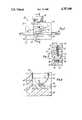
- FIG. 1is a front plan view showing an embodiment of the clamp apparatus of this invention.
- FIG. 2is a cross-sectional view taken along line 2--2 of FIG. 1.
- FIG. 3is a detailed, side cross-sectional view of certain components of the embodiment shown in FIG. 1 demonstrating total occlusion of the intravenous tubing.
- a flow control clampaccording to the present invention, shown generally at 10, includes a rigid supporting structure or housing 12, a force-applying member in the form of a plunger 14, a threaded screw 16, a turn knob 18 and an elastomer pad 20.
- Housing 12includes a base 22, a cavity 24, a first passage 26, a second passage 28 and a threaded hole 30 extending from cavity 24 to the top 32 of housing 12.
- Plunger 14includes a depending, hemispherically-shaped force-applying surface or anvil 34.
- Plunger 14is situated in cavity 24 and has two, mutually opposing flat surfaces 15 and 17. Flat surface 17 buts up against housing 12 and thereby prevents turning of plunger 14. Threaded screw 16 extends into plunger 14 and is associated with plunger 14 such that when threaded screw 16 turns toward elastomer pad 20, plunger 14 moves toward elastomer pad 20. Elastomer pad 20, along with the fluid filled flexible intravenous tubing 36 acts to cause plunger 14 to move away from elastomer pad 20 when threaded screw 16 is turned away from elastomer pad 20. The threads of threaded screw 16 are sized and adapted to mate with the threads of threaded hole 30. Threaded screw 16 is also secured to turn knob 18 so that threaded screw 16 turns as turn knob 18 is turned.
- Plunger 14is substantially rigid and terminates at the end away from threaded screw 16 in the hemispherical-shaped anvil 34.
- the diameter of anvil 34is larger than the diameter of the flexible intravenous tubing 36, the flow through which is to be controlled. In the embodiment shown in the drawings, the diameter of anvil 34 is approximately three (3) times the normal outside diameter of flexible intravenous tube or tubing 36 in the unstressed condition of the tubing 36.
- Plunger 14 and anvil 34are situated and structured to apply a force to tubing 36 substantially perpendicular to the longitudinal axis of tubing 36 to squeeze tubing 36 between anvil 34 and elastomer pad 20 as plunger 14 moves down toward elastomer pad 20 in response to the turning of turn knob 18.
- Tubing 36is passed into housing 12 through first passage 26 and second passage 28, which are situated so that tubing 36 passes through cavity 24 between anvil 34 and elastomer pad 20.
- Elastomer pad 20is adhesively secured to base 22 and is located substantially within cavity 24. Elastomer pad 20 is situated and configured so as to present a normally substantially flat surface for contact with tubing 36. That is, the top surface 38 of elastomer pad 20 is substantially flat when anvil 34 is not in contact with tubing 36.
- Elastomer pad 20is constructed of resilient, synthetic elastomer polymer.
- the specific material used for elastomer pad 20depends on the specific application involved and, in particular, on the material of construction and configuration of flexible tubing 36 and anvil 34.
- Elastomer pad 20is preferably structured so that as anvil 34 contacts tubing 36 to further partially occlude tubing 36, a portion of the movement of anvil 34 is translated into movement, e.g., compression, of elastomer pad 20.
- Elastomer pad 20preferably has sufficient rigidity so that it is possible to completely occlude tubing 36 using the movement of anvil 34, as desired, as indicated in FIG. 3.
- clamp 10as shown is to be manually operated, such a device can be constructed to be automatically operated.
- a motor or similar devicecan be used to control the movement of plunger 14 and anvil 34.
- Clamp 10is structured so that once plunger 14 and anvil 34 are moved to achieve the desired degree of occlusion of tubing 36, that desired degree of occlusion is maintained until plunger 14 and anvil 34 are again manually moved.
- clamp 10allows for a substantially continuous range of degrees of partial occlusion of tubing 36.
- Clamp 10functions as follows. Plunger 14 and anvil 34 are moved toward top 32 of housing 12 so that flexible tubing 36 can be passed into housing 12 through first passage 26 and second passage 28, Fluid, e.g., liquid, is caused to flow through tubing 36. Turn knob 18 is turned to cause anvil 34 to move into initial point contact with tubing 36. Turn knob 18 is further turned to move the anvil 34 farther downwardly to enlarge the point contact radially thereby flattening the tubing until the desired degree of partial occlusion of tubing 36, i.e., until the desired flow rate of fluid through tubing 36, is achieved. At this point, the turning is stopped and the desired fluid flow rate though tubing 36 is maintained.
- Fluide.g., liquid
- the force on tubing 36can be adjusted, as desired, by moving anvil 34 up or down, as desired, to obtain a different degree of partial occlusion of tubing 36, i.e., a different fluid flow rate through tubing 36. If it is desired to completely stop the flow of fluid through tubing 36, turn knob 18 is turned until anvil 34 is moved so as to completely occlude tubing 36. The part spherical anvil 34 cooperates with the resilient pad 20 to effectively occlude the tubing 36 such that even the ends 40 (FIG. 3) of the passage through the tubing are completely closed. This state of total occlusion is maintained until turn knob 18 is manually turned to move anvil 34 away from elastomer pad 20.
- the present systemis mechanically simple, easy to operate and maintain, and provides effective and reliable control of fluid flow rates, e.g., of intravenous fluid flow rates. Importantly, the system provides for precise control of flow rates and for conveniently “fine tuning" such flow rates. In short, the apparatus and method of the present invention are both cost effective and operationally effective in controlling fluid flow rates.
Landscapes
- Health & Medical Sciences (AREA)
- Heart & Thoracic Surgery (AREA)
- Pulmonology (AREA)
- Engineering & Computer Science (AREA)
- Anesthesiology (AREA)
- Biomedical Technology (AREA)
- Hematology (AREA)
- Life Sciences & Earth Sciences (AREA)
- Animal Behavior & Ethology (AREA)
- General Health & Medical Sciences (AREA)
- Public Health (AREA)
- Veterinary Medicine (AREA)
- Infusion, Injection, And Reservoir Apparatuses (AREA)
Abstract
Description
Claims (21)
Priority Applications (1)
| Application Number | Priority Date | Filing Date | Title |
|---|---|---|---|
| US07/098,844US4787406A (en) | 1987-09-21 | 1987-09-21 | Fluid flow control clamp and method for using same |
Applications Claiming Priority (1)
| Application Number | Priority Date | Filing Date | Title |
|---|---|---|---|
| US07/098,844US4787406A (en) | 1987-09-21 | 1987-09-21 | Fluid flow control clamp and method for using same |
Publications (1)
| Publication Number | Publication Date |
|---|---|
| US4787406Atrue US4787406A (en) | 1988-11-29 |
Family
ID=22271188
Family Applications (1)
| Application Number | Title | Priority Date | Filing Date |
|---|---|---|---|
| US07/098,844Expired - LifetimeUS4787406A (en) | 1987-09-21 | 1987-09-21 | Fluid flow control clamp and method for using same |
Country Status (1)
| Country | Link |
|---|---|
| US (1) | US4787406A (en) |
Cited By (44)
| Publication number | Priority date | Publication date | Assignee | Title |
|---|---|---|---|---|
| WO1990005471A1 (en)* | 1988-11-17 | 1990-05-31 | Bodine Oliver H Jr | Bed system |
| US4966585A (en)* | 1988-05-31 | 1990-10-30 | Gangemi Ronald J | Infusion apparatus |
| US5013006A (en)* | 1989-07-24 | 1991-05-07 | Cosmo Instruments Co., Ltd. | Micro-leakage regulating valve |
| USD325631S (en) | 1989-09-25 | 1992-04-21 | Ivac Corporation | Medical tube clamp |
| US5216768A (en)* | 1988-11-17 | 1993-06-08 | Oliver H. Bodine, Jr. | Bed system |
| US5259587A (en)* | 1992-06-08 | 1993-11-09 | Whitman Medical Corporation | Roller clamp |
| US5297526A (en)* | 1992-03-27 | 1994-03-29 | Braddock Douglas J | Glow-plug engine |
| US5316262A (en)* | 1992-01-31 | 1994-05-31 | Suprex Corporation | Fluid restrictor apparatus and method for making the same |
| US5372716A (en)* | 1991-02-28 | 1994-12-13 | Suprex Corporation | Supercritical fluid extraction coupled to analytical chromatography system |
| US5458783A (en)* | 1992-08-13 | 1995-10-17 | Suprex Corporation | Supercritical fluid extraction coupled to analytical chromatography system |
| USD389228S (en) | 1996-03-19 | 1998-01-13 | Zevex, Inc. | Pinch clip occluder |
| GB2338531A (en)* | 1998-05-05 | 1999-12-22 | Colm Joseph Mcmanus | Pipe clamp |
| US20030071233A1 (en)* | 2001-10-12 | 2003-04-17 | Stewart Neil G. | Fluid flow adjustment mechanism |
| EP1308657A3 (en)* | 2001-11-03 | 2003-12-10 | A. und K. Müller GmbH & Co. KG | Shut-off device for flowing media |
| US20040200985A1 (en)* | 2003-04-08 | 2004-10-14 | Aquapore Moisture Systems, Inc. | Spigot |
| US20060009739A1 (en)* | 2002-09-06 | 2006-01-12 | Durect Corporation | Implantable flow regulator with failsafe mode and reserve drug supply |
| US7686279B2 (en) | 2006-05-12 | 2010-03-30 | Caridianbct, Inc. | Non-reopenable clamp for tubing sets |
| US20100082001A1 (en)* | 2008-04-01 | 2010-04-01 | Kent Beck | Anti-free flow mechanism for enteral feeding pumps |
| US7998121B2 (en) | 2009-02-06 | 2011-08-16 | Zevex, Inc. | Automatic safety occluder |
| USD672455S1 (en) | 2010-10-01 | 2012-12-11 | Zevex, Inc. | Fluid delivery cassette |
| US8425470B2 (en) | 2008-04-01 | 2013-04-23 | Zevex, Inc. | Anti-free-flow mechanism for enteral feeding pumps |
| US20130118619A1 (en)* | 2010-06-02 | 2013-05-16 | Technische Universität Berlin | Valve device for controlling a flow of a fluid through a fluid channel, arrangement and multi-way valve device |
| US8911414B2 (en) | 2010-10-01 | 2014-12-16 | Zevex, Inc. | Anti free-flow occluder and priming actuator pad |
| US8940228B2 (en) | 2012-01-11 | 2015-01-27 | Terumo Bct, Inc. | Slidable clamp for port isolation |
| US9017296B2 (en) | 2008-04-01 | 2015-04-28 | Zevex, Inc. | Safety occluder and method of use |
| CN104721910A (en)* | 2015-03-26 | 2015-06-24 | 江苏阳普医疗科技有限公司 | Multi-flow speed controller of analgesia pump |
| CN104771811A (en)* | 2015-04-13 | 2015-07-15 | 无锡市人民医院 | Novel infusion speed control device |
| US20150216622A1 (en)* | 2014-02-05 | 2015-08-06 | Albert Vartanian | Ergonomically optimized, in-line water valve assembly for use with a dental handpiece |
| CN105142697A (en)* | 2013-03-15 | 2015-12-09 | 德卡产品有限公司 | Systems, methods and devices for monitoring, regulating or controlling fluid flow |
| US9289169B2 (en) | 2007-05-18 | 2016-03-22 | Optiscan Biomedical Corp. | Analyte monitoring systems and methods |
| CN104399148B (en)* | 2014-11-24 | 2017-01-25 | 芮冬梅 | Venous transfusion adjusting and monitoring device and monitoring system |
| US9863837B2 (en) | 2013-12-18 | 2018-01-09 | OptiScan Biomedical Coporation | Systems and methods for detecting leaks |
| US10228683B2 (en) | 2011-12-21 | 2019-03-12 | Deka Products Limited Partnership | System, method, and apparatus for monitoring, regulating, or controlling fluid flow |
| CN109908430A (en)* | 2019-01-09 | 2019-06-21 | 株式会社吉美医疗 | A kind of medical blood vessel intubator for reinforcing safety |
| USD860437S1 (en) | 2016-05-25 | 2019-09-17 | Deka Products Limited Partnership | Apparatus to control fluid flow through a tube |
| US10436342B2 (en) | 2011-12-21 | 2019-10-08 | Deka Products Limited Partnership | Flow meter and related method |
| US10876868B2 (en) | 2011-12-21 | 2020-12-29 | Deka Products Limited Partnership | System, method, and apparatus for monitoring, regulating, or controlling fluid flow |
| US10894638B2 (en) | 2011-12-21 | 2021-01-19 | Deka Products Limited Partnership | System, method, and apparatus for monitoring, regulating, or controlling fluid flow |
| US11033707B2 (en)* | 2015-10-12 | 2021-06-15 | Lungflex Ab | Portable control device for regulating a continous oxygen flow |
| USD964563S1 (en) | 2019-07-26 | 2022-09-20 | Deka Products Limited Partnership | Medical flow clamp |
| US11738143B2 (en) | 2011-12-21 | 2023-08-29 | Deka Products Limited Partnership | Flow meier having a valve |
| US11744935B2 (en) | 2016-01-28 | 2023-09-05 | Deka Products Limited Partnership | Apparatus for monitoring, regulating, or controlling fluid flow |
| US11752309B2 (en)* | 2021-09-22 | 2023-09-12 | Mark Wayne LENOX | Catheter delivery guidewire clamp |
| US11839741B2 (en) | 2019-07-26 | 2023-12-12 | Deka Products Limited Partneship | Apparatus for monitoring, regulating, or controlling fluid flow |
Citations (21)
| Publication number | Priority date | Publication date | Assignee | Title |
|---|---|---|---|---|
| US715429A (en)* | 1902-04-09 | 1902-12-09 | George J Seabury | Tube-compressor. |
| US2215725A (en)* | 1939-07-13 | 1940-09-24 | Raymond W Martinson | Embalming clamp |
| US2314767A (en)* | 1942-03-18 | 1943-03-23 | Burrell Technical Supply Compa | Adjustable rubber valve |
| US2908476A (en)* | 1955-01-03 | 1959-10-13 | Walter E Hidding | Tube clamp |
| US3167085A (en)* | 1962-02-12 | 1965-01-26 | Abbott Lab | Flow regulating device |
| US3332439A (en)* | 1965-08-18 | 1967-07-25 | Burron Medical Prod Inc | Flow regulating apparatus |
| US3361162A (en)* | 1966-02-17 | 1968-01-02 | Allis Chalmers Mfg Co | Fluid flow controller |
| US3512748A (en)* | 1967-08-14 | 1970-05-19 | Pacific Plantronics Inc | Fluid-flow controller |
| US3550619A (en)* | 1968-06-21 | 1970-12-29 | Becton Dickinson Co | Tubing holder |
| US3831600A (en)* | 1973-04-02 | 1974-08-27 | Alza Corp | Fluid flow control |
| US3848634A (en)* | 1972-08-16 | 1974-11-19 | United States Surgical Corp | Fluid control system for controlling intravenous flow rate |
| US3926175A (en)* | 1974-06-03 | 1975-12-16 | James H Allen | Implantable valve for medical purposes |
| US3948477A (en)* | 1973-07-02 | 1976-04-06 | United States Surgical Corporation | Screw clamp for flexible tubing |
| US3993076A (en)* | 1973-08-20 | 1976-11-23 | Fogarty Thomas J | Vessel occluding instrument |
| US4081170A (en)* | 1976-04-12 | 1978-03-28 | Doss Jr Desmond T | Clamp for tubular bodies |
| US4106508A (en)* | 1976-08-31 | 1978-08-15 | Richard Barnard Berlin | Clamp device |
| US4312493A (en)* | 1979-05-05 | 1982-01-26 | Stauffer Rita A | Apparatus for controlled liquid administration |
| US4337791A (en)* | 1980-11-17 | 1982-07-06 | La-Van Tech Development Corp. | Flow regulator assembly |
| US4475709A (en)* | 1979-12-10 | 1984-10-09 | Becker Jr Karl E | Intravenous tubing clamping device |
| US4482347A (en)* | 1982-08-12 | 1984-11-13 | American Hospital Supply Corporation | Peristaltic fluid-pumping apparatus |
| US4575041A (en)* | 1985-01-17 | 1986-03-11 | Hu Liang Tung | Liquid flow controller |
- 1987
- 1987-09-21USUS07/098,844patent/US4787406A/ennot_activeExpired - Lifetime
Patent Citations (21)
| Publication number | Priority date | Publication date | Assignee | Title |
|---|---|---|---|---|
| US715429A (en)* | 1902-04-09 | 1902-12-09 | George J Seabury | Tube-compressor. |
| US2215725A (en)* | 1939-07-13 | 1940-09-24 | Raymond W Martinson | Embalming clamp |
| US2314767A (en)* | 1942-03-18 | 1943-03-23 | Burrell Technical Supply Compa | Adjustable rubber valve |
| US2908476A (en)* | 1955-01-03 | 1959-10-13 | Walter E Hidding | Tube clamp |
| US3167085A (en)* | 1962-02-12 | 1965-01-26 | Abbott Lab | Flow regulating device |
| US3332439A (en)* | 1965-08-18 | 1967-07-25 | Burron Medical Prod Inc | Flow regulating apparatus |
| US3361162A (en)* | 1966-02-17 | 1968-01-02 | Allis Chalmers Mfg Co | Fluid flow controller |
| US3512748A (en)* | 1967-08-14 | 1970-05-19 | Pacific Plantronics Inc | Fluid-flow controller |
| US3550619A (en)* | 1968-06-21 | 1970-12-29 | Becton Dickinson Co | Tubing holder |
| US3848634A (en)* | 1972-08-16 | 1974-11-19 | United States Surgical Corp | Fluid control system for controlling intravenous flow rate |
| US3831600A (en)* | 1973-04-02 | 1974-08-27 | Alza Corp | Fluid flow control |
| US3948477A (en)* | 1973-07-02 | 1976-04-06 | United States Surgical Corporation | Screw clamp for flexible tubing |
| US3993076A (en)* | 1973-08-20 | 1976-11-23 | Fogarty Thomas J | Vessel occluding instrument |
| US3926175A (en)* | 1974-06-03 | 1975-12-16 | James H Allen | Implantable valve for medical purposes |
| US4081170A (en)* | 1976-04-12 | 1978-03-28 | Doss Jr Desmond T | Clamp for tubular bodies |
| US4106508A (en)* | 1976-08-31 | 1978-08-15 | Richard Barnard Berlin | Clamp device |
| US4312493A (en)* | 1979-05-05 | 1982-01-26 | Stauffer Rita A | Apparatus for controlled liquid administration |
| US4475709A (en)* | 1979-12-10 | 1984-10-09 | Becker Jr Karl E | Intravenous tubing clamping device |
| US4337791A (en)* | 1980-11-17 | 1982-07-06 | La-Van Tech Development Corp. | Flow regulator assembly |
| US4482347A (en)* | 1982-08-12 | 1984-11-13 | American Hospital Supply Corporation | Peristaltic fluid-pumping apparatus |
| US4575041A (en)* | 1985-01-17 | 1986-03-11 | Hu Liang Tung | Liquid flow controller |
Cited By (67)
| Publication number | Priority date | Publication date | Assignee | Title |
|---|---|---|---|---|
| US4966585A (en)* | 1988-05-31 | 1990-10-30 | Gangemi Ronald J | Infusion apparatus |
| WO1990005471A1 (en)* | 1988-11-17 | 1990-05-31 | Bodine Oliver H Jr | Bed system |
| US5216768A (en)* | 1988-11-17 | 1993-06-08 | Oliver H. Bodine, Jr. | Bed system |
| US5013006A (en)* | 1989-07-24 | 1991-05-07 | Cosmo Instruments Co., Ltd. | Micro-leakage regulating valve |
| USD325631S (en) | 1989-09-25 | 1992-04-21 | Ivac Corporation | Medical tube clamp |
| US5372716A (en)* | 1991-02-28 | 1994-12-13 | Suprex Corporation | Supercritical fluid extraction coupled to analytical chromatography system |
| US5316262A (en)* | 1992-01-31 | 1994-05-31 | Suprex Corporation | Fluid restrictor apparatus and method for making the same |
| US5297526A (en)* | 1992-03-27 | 1994-03-29 | Braddock Douglas J | Glow-plug engine |
| US5259587A (en)* | 1992-06-08 | 1993-11-09 | Whitman Medical Corporation | Roller clamp |
| US5458783A (en)* | 1992-08-13 | 1995-10-17 | Suprex Corporation | Supercritical fluid extraction coupled to analytical chromatography system |
| USD389228S (en) | 1996-03-19 | 1998-01-13 | Zevex, Inc. | Pinch clip occluder |
| GB2338531A (en)* | 1998-05-05 | 1999-12-22 | Colm Joseph Mcmanus | Pipe clamp |
| GB2338531B (en)* | 1998-05-05 | 2003-04-09 | Colm Joseph Mcmanus | A pipe clamp |
| US20030071233A1 (en)* | 2001-10-12 | 2003-04-17 | Stewart Neil G. | Fluid flow adjustment mechanism |
| US7569028B2 (en)* | 2001-10-12 | 2009-08-04 | Flexcorp | Fluid flow adjustment mechanism |
| EP1308657A3 (en)* | 2001-11-03 | 2003-12-10 | A. und K. Müller GmbH & Co. KG | Shut-off device for flowing media |
| US20060264913A1 (en)* | 2002-09-06 | 2006-11-23 | Poutiatine Andrew I | Implantable flow regulator with failsafe mode and reserve drug supply |
| US20060009739A1 (en)* | 2002-09-06 | 2006-01-12 | Durect Corporation | Implantable flow regulator with failsafe mode and reserve drug supply |
| EP1467273A3 (en)* | 2003-04-08 | 2005-09-07 | Aquapore Moisture Systems, Inc. | Spigot |
| US7121521B2 (en) | 2003-04-08 | 2006-10-17 | Fiskars Brands, Inc. | Spigot |
| US20040200985A1 (en)* | 2003-04-08 | 2004-10-14 | Aquapore Moisture Systems, Inc. | Spigot |
| US7686279B2 (en) | 2006-05-12 | 2010-03-30 | Caridianbct, Inc. | Non-reopenable clamp for tubing sets |
| US9289169B2 (en) | 2007-05-18 | 2016-03-22 | Optiscan Biomedical Corp. | Analyte monitoring systems and methods |
| US8343111B2 (en) | 2008-04-01 | 2013-01-01 | Zevex, Inc. | Anti-free flow mechanism for enteral feeding pumps |
| US8425470B2 (en) | 2008-04-01 | 2013-04-23 | Zevex, Inc. | Anti-free-flow mechanism for enteral feeding pumps |
| US8876787B2 (en) | 2008-04-01 | 2014-11-04 | Zevex, Inc. | Anti-free-flow mechanism for enteral feeding pumps |
| US20100082001A1 (en)* | 2008-04-01 | 2010-04-01 | Kent Beck | Anti-free flow mechanism for enteral feeding pumps |
| US9017296B2 (en) | 2008-04-01 | 2015-04-28 | Zevex, Inc. | Safety occluder and method of use |
| US7998121B2 (en) | 2009-02-06 | 2011-08-16 | Zevex, Inc. | Automatic safety occluder |
| US8491543B2 (en) | 2009-02-06 | 2013-07-23 | Zevex, Inc. | Automatic safety occluder |
| US20130118619A1 (en)* | 2010-06-02 | 2013-05-16 | Technische Universität Berlin | Valve device for controlling a flow of a fluid through a fluid channel, arrangement and multi-way valve device |
| US9067051B2 (en)* | 2010-06-02 | 2015-06-30 | Technische Universitat Berlin | Valve device for controlling a flow of a fluid through a fluid channel, arrangement and multi-way valve device |
| USD672455S1 (en) | 2010-10-01 | 2012-12-11 | Zevex, Inc. | Fluid delivery cassette |
| US8911414B2 (en) | 2010-10-01 | 2014-12-16 | Zevex, Inc. | Anti free-flow occluder and priming actuator pad |
| US10876868B2 (en) | 2011-12-21 | 2020-12-29 | Deka Products Limited Partnership | System, method, and apparatus for monitoring, regulating, or controlling fluid flow |
| US10844970B2 (en) | 2011-12-21 | 2020-11-24 | Deka Products Limited Partnership | Flow meter |
| US12100507B2 (en) | 2011-12-21 | 2024-09-24 | Deka Products Limited Partnership | System, method, and apparatus for monitoring, regulating, or controlling fluid flow |
| US11793928B2 (en) | 2011-12-21 | 2023-10-24 | Deka Products Limited Partnership | Flow meter and related method |
| US11738143B2 (en) | 2011-12-21 | 2023-08-29 | Deka Products Limited Partnership | Flow meier having a valve |
| US11574407B2 (en) | 2011-12-21 | 2023-02-07 | Deka Products Limited Partnership | System, method, and apparatus for monitoring, regulating, or controlling fluid flow |
| US11449037B2 (en) | 2011-12-21 | 2022-09-20 | Deka Products Limited Partnership | System, method, and apparatus for monitoring, regulating, or controlling fluid flow |
| US10228683B2 (en) | 2011-12-21 | 2019-03-12 | Deka Products Limited Partnership | System, method, and apparatus for monitoring, regulating, or controlling fluid flow |
| US11339887B2 (en) | 2011-12-21 | 2022-05-24 | Deka Products Limited Partnership | Flow meter and related method |
| US10894638B2 (en) | 2011-12-21 | 2021-01-19 | Deka Products Limited Partnership | System, method, and apparatus for monitoring, regulating, or controlling fluid flow |
| US10436342B2 (en) | 2011-12-21 | 2019-10-08 | Deka Products Limited Partnership | Flow meter and related method |
| US10739759B2 (en) | 2011-12-21 | 2020-08-11 | Deka Products Limited Partnership | System, method, and apparatus for monitoring, regulating, or controlling fluid flow |
| US8940228B2 (en) | 2012-01-11 | 2015-01-27 | Terumo Bct, Inc. | Slidable clamp for port isolation |
| CN113975535A (en)* | 2013-03-15 | 2022-01-28 | 德卡产品有限公司 | Systems, methods, and devices for monitoring, regulating, or controlling fluid flow |
| CN113975535B (en)* | 2013-03-15 | 2025-02-07 | 德卡产品有限公司 | Systems, methods and devices for monitoring, regulating or controlling fluid flow |
| CN111135382B (en)* | 2013-03-15 | 2022-06-14 | 德卡产品有限公司 | Systems, methods and apparatus for monitoring, regulating or controlling fluid flow |
| CN105142697A (en)* | 2013-03-15 | 2015-12-09 | 德卡产品有限公司 | Systems, methods and devices for monitoring, regulating or controlling fluid flow |
| CN111135382A (en)* | 2013-03-15 | 2020-05-12 | 德卡产品有限公司 | Systems, methods and apparatus for monitoring, regulating or controlling fluid flow |
| US9863837B2 (en) | 2013-12-18 | 2018-01-09 | OptiScan Biomedical Coporation | Systems and methods for detecting leaks |
| US20150216622A1 (en)* | 2014-02-05 | 2015-08-06 | Albert Vartanian | Ergonomically optimized, in-line water valve assembly for use with a dental handpiece |
| CN104399148B (en)* | 2014-11-24 | 2017-01-25 | 芮冬梅 | Venous transfusion adjusting and monitoring device and monitoring system |
| CN104721910A (en)* | 2015-03-26 | 2015-06-24 | 江苏阳普医疗科技有限公司 | Multi-flow speed controller of analgesia pump |
| CN104771811A (en)* | 2015-04-13 | 2015-07-15 | 无锡市人民医院 | Novel infusion speed control device |
| US11033707B2 (en)* | 2015-10-12 | 2021-06-15 | Lungflex Ab | Portable control device for regulating a continous oxygen flow |
| US11744935B2 (en) | 2016-01-28 | 2023-09-05 | Deka Products Limited Partnership | Apparatus for monitoring, regulating, or controlling fluid flow |
| USD972125S1 (en) | 2016-05-25 | 2022-12-06 | Deka Products Limited Partnership | Apparatus to control fluid flow through a tube |
| USD972718S1 (en) | 2016-05-25 | 2022-12-13 | Deka Products Limited Partnership | Apparatus to control fluid flow through a tube |
| USD1060608S1 (en) | 2016-05-25 | 2025-02-04 | Deka Products Limited Partnership | Device to control fluid flow through a tube |
| USD860437S1 (en) | 2016-05-25 | 2019-09-17 | Deka Products Limited Partnership | Apparatus to control fluid flow through a tube |
| CN109908430A (en)* | 2019-01-09 | 2019-06-21 | 株式会社吉美医疗 | A kind of medical blood vessel intubator for reinforcing safety |
| USD964563S1 (en) | 2019-07-26 | 2022-09-20 | Deka Products Limited Partnership | Medical flow clamp |
| US11839741B2 (en) | 2019-07-26 | 2023-12-12 | Deka Products Limited Partneship | Apparatus for monitoring, regulating, or controlling fluid flow |
| US11752309B2 (en)* | 2021-09-22 | 2023-09-12 | Mark Wayne LENOX | Catheter delivery guidewire clamp |
Similar Documents
| Publication | Publication Date | Title |
|---|---|---|
| US4787406A (en) | Fluid flow control clamp and method for using same | |
| US4065093A (en) | Flow control device | |
| US4781674A (en) | Fluid flow control valve | |
| US4904236A (en) | Fluid flow control valve | |
| EP2101846B1 (en) | Flow controller | |
| US3848634A (en) | Fluid control system for controlling intravenous flow rate | |
| US5396925A (en) | Anti-free flow valve, enabling fluid flow as a function of pressure and selectively opened to enable free flow | |
| EP0341488B1 (en) | Pressure membrane device for infusions | |
| CA1219851A (en) | Precision valve assembly | |
| DE69720744T2 (en) | VALVE FOR USE WITH AN INTRAVENOUS DEVICE | |
| DE69736754T2 (en) | Extracorporeal slot valve and control for opening and closing the slot | |
| US3913882A (en) | Device for controlling the flow of fluid through flexible tubes | |
| US4660802A (en) | Liquid flow control device | |
| EP0341237A1 (en) | Arrangement for controlling and regulating a liquid flowing through a line | |
| US4332369A (en) | Adjustable in-line intravenous valve with locking mechanism | |
| AU595001B2 (en) | A flow regulator for liquids | |
| US4266697A (en) | Controlled volume liquid meter defining improved plunger means | |
| US4687176A (en) | Flow control valve for a flexible walled tube | |
| ATE497798T1 (en) | DEVICE FOR SELF-DOSING AND CONTROLLING THE DOSAGE OF A LIQUID MEDICATION | |
| US5718409A (en) | Flow regulator | |
| EP0747090B1 (en) | Fluid flow control device, in particular for infusing intravenous fluids | |
| EP0246110B1 (en) | Valve for controlling the flow of liquid through a tube | |
| JP4056815B2 (en) | Flow regulator | |
| US4573658A (en) | Adjustable in-line valve for sterile fluids | |
| JP2727350B2 (en) | Flow controller and transfusion set using the same |
Legal Events
| Date | Code | Title | Description |
|---|---|---|---|
| AS | Assignment | Owner name:BAXTER TRAVENOL LABORATORIES, INC., ONE BAXTER PAR Free format text:ASSIGNMENT OF ASSIGNORS INTEREST.;ASSIGNORS:EDWARDS, FRED;BARR, ERIC;REEL/FRAME:004788/0835 Effective date:19870825 Owner name:BAXTER TRAVENOL LABORATORIES, INC., ONE BAXTER PAR Free format text:ASSIGNMENT OF ASSIGNORS INTEREST;ASSIGNORS:EDWARDS, FRED;BARR, ERIC;REEL/FRAME:004788/0835 Effective date:19870825 | |
| STCF | Information on status: patent grant | Free format text:PATENTED CASE | |
| CC | Certificate of correction | ||
| FPAY | Fee payment | Year of fee payment:4 | |
| FEPP | Fee payment procedure | Free format text:PAYOR NUMBER ASSIGNED (ORIGINAL EVENT CODE: ASPN); ENTITY STATUS OF PATENT OWNER: LARGE ENTITY | |
| FPAY | Fee payment | Year of fee payment:8 | |
| REMI | Maintenance fee reminder mailed | ||
| FEPP | Fee payment procedure | Free format text:PAYOR NUMBER ASSIGNED (ORIGINAL EVENT CODE: ASPN); ENTITY STATUS OF PATENT OWNER: LARGE ENTITY Free format text:PAYER NUMBER DE-ASSIGNED (ORIGINAL EVENT CODE: RMPN); ENTITY STATUS OF PATENT OWNER: LARGE ENTITY | |
| FPAY | Fee payment | Year of fee payment:12 |