US4787183A - Truss arrangement - Google Patents
Truss arrangementDownload PDFInfo
- Publication number
- US4787183A US4787183AUS06/813,242US81324285AUS4787183AUS 4787183 AUS4787183 AUS 4787183AUS 81324285 AUS81324285 AUS 81324285AUS 4787183 AUS4787183 AUS 4787183A
- Authority
- US
- United States
- Prior art keywords
- truss
- legs
- members
- chord
- upright members
- Prior art date
- Legal status (The legal status is an assumption and is not a legal conclusion. Google has not performed a legal analysis and makes no representation as to the accuracy of the status listed.)
- Expired - Lifetime
Links
Images


Classifications
- E—FIXED CONSTRUCTIONS
- E04—BUILDING
- E04G—SCAFFOLDING; FORMS; SHUTTERING; BUILDING IMPLEMENTS OR AIDS, OR THEIR USE; HANDLING BUILDING MATERIALS ON THE SITE; REPAIRING, BREAKING-UP OR OTHER WORK ON EXISTING BUILDINGS
- E04G11/00—Forms, shutterings, or falsework for making walls, floors, ceilings, or roofs
- E04G11/36—Forms, shutterings, or falsework for making walls, floors, ceilings, or roofs for floors, ceilings, or roofs of plane or curved surfaces end formpanels for floor shutterings
- E04G11/48—Supporting structures for shutterings or frames for floors or roofs
Definitions
- the present inventionrelates to forms and components thereof for use in concrete forming and in particular, forms and components thereof which include trusses for forming of concrete floors.
- the formspreferrably are of the type that are adapted to be lifted by crane between floors of a building during the construction thereof, thereby substantially reducing the time required to set up the form for pouring of the next floor.
- the inventionis directed to forms which provide additional flexibility and convenient adjustment to define a system for forming of ceilings of different heights or vaulted ceilings.
- Flying formswhich are essentially a number of interconnected truss structures adapted to be moved on rollers or the like beyond the building and lifted to the next floor, greatly reduce the required labour necessary for set-up of the forms.
- forms of this typeinclude U.S. Pat. Nos. 4,077,172, 3,966,164, 3,787,020 as but some examples.
- Recent architectural design to provide additional strengthhas used concrete ceilings provided with concrete beams which require a stepped ceiling. It is also common to provide a concrete sill at the edge of the floor and a downwardly extending edge portion from the ceiling to reduce the window size.
- Such structurespresent additional problems as "packing" is required on the top surface of the truss to accomodate the changing heights of the ceiling.
- a systemwhich uses an intermediate truss which has extendable legs associated therewith. Certain of the legs are associated with the truss to extend below the truss for engaging a support surface and other legs extend above the truss to engage a load collecting beams. Movement of the truss between floors is possible as the lower extension legs collapse or telescope within the truss.
- the trussis such that the legs each telescope within their own associated tube or recess of the truss whereby the length of the leg can be approximately equal to the height of the truss and, it can be extended further by use of a screw jack.
- An upright member for a trusscomprises two paired members disposed in parallel relation and connected to each other by connecting means intermediate the said members.
- Each of the membersincludes generally planar opposed parallel bearing surfaces and each bearing surface on one member is colinear with a bearing surface on the other tube member.
- FIG. 1is a partial perspective view of a truss used in concrete forming
- FIG. 2is a partial perspective view of a portion of a truss illustrating the co-operation of the upright support members with the top and bottom chords of the truss;
- FIG. 3is a partial perspective view showing additional details of the co-operation between the upright member and the top and bottom chords of the truss;
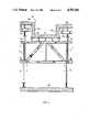
- FIG. 4is a partial front view of the concrete forming system showing a partial section of a vaulted ceiling
- FIG. 5is a partial front view of a portion of the truss system adapted for forming of a ledge at the edge of the floor;
- FIG. 6is view similar to FIG. 5 with the truss in its retracted state for removal from between concrete floors.
- FIG. 7is a partial cut-away perspective view of the truss system with a modified construction
- FIG. 8is a top view of the modified upright.
- FIG. 9is a partial sideview of the modified upright.
- the concrete forming system generally shown as 2 in FIG. 1has parallel trusses 3 and 4, each having a top chord member 6 and a bottom chord member 8, spaced by upright members 10 and truss diagonal braces 12.
- the trussesare interconnected by the braces 14.
- Load collecting beams 22preferrably run parallel with the top chord 6 of each truss or perpendicular to the top chords 6.
- the sheeting material 20is secured atop the beams 18 and at least partially defines the concrete form.
- a number of trusses 6can be interconnected for forming larger areas and can be moved as a unit depending upon the construction site and the crane capacity.
- 3 different concrete forming levelsare shown for accomodating concrete beams and stepped areas formed as part of the floor.
- Load collecting beams 22are appropriately positioned by extendable legs 24 or screw jacks as shown, of a size for receipt within an upright member 10.
- Extendable legs 26are positioned adjacent the bottom edge of the truss, support the truss at the required height above a support floor. Therefore, the truss, defined between the top chord member 6 and the bottom chord member 8, is positionable at various spacings above a support floor by adjusting the lower extendable legs 26.
- Extendable legs 24allow for fast positioning of load collecting beams 22, in accordance with the desired ceiling profile.
- the legs 24 and 26are telescopically received within the upright members 10 without interference between leg 24 and 26. This occurs as the legs are adjacent to each other and each upright member 10 has the capacity for receiving two legs.
- FIG. 2Details of the telescopic receipt of extendable leg 24 and extendable leg 26 within one of the upright members 10 can be appreciated from FIG. 2, where upright member 10 has two opposed members 32 and 34, each of a size for receiving an extension leg. Webs 36 and 38 in combination with members 32 and 34, define a closed cavity 40. This cavity is advantageously used to receive bolts 92 for connecting the upright member 10 to the chord members 6 and 8. As the bolts pass through the cavity 40, the hollow portion within each of the tube members 32 and 34 remains clear and allows extendable legs 24 and 26 to collapse or telescope within the full length of each tube member. To the exterior of web members 36 and 38, bolt slots 42 and 44 are provided.
- Bolt slot 42has exterior flanges 46 and 48 which define a planar face for engaging the interior surface of the side plate 62 of the bottom chord member 8 and the interior surfaces of the side plate 82 of the top chord member.
- Bolt slot 44includes similar flanges and cooperates with side plates 64 and 84.
- each tube memberincludes opposed thickened portions 50 and 52 having a planar outer face. The face of portions 50 are co-planar with flanges 48 and 46 which also engage the interior surface of the bottom chord member and the top chord member to provide a more secure fit of the upright member within the chord members.
- Portion 52cooperates with the flanges of bolt slot 44 to engage the opposite side plates of the top and bottom chord.
- the bolts 92pass through the side plates of the chord members and through the bolt slots to apply the pressure adjacent these planar engaging faces to increase the structural integrity of the system.
- the uprightsare preferrably extruded of a magnesium or aluminum alloy although not limited thereto.
- the top chord member 6includes a top plate 80 which extends beyond the side plates 82 and 84 to define downwardly extending lips 86, either side of the longtitudal axis of the top chord member 6. These lips 86 are used for clamping of additional components to the top chord member.
- the top plate 80includes a circular opening 81 to allow access to the hollow interior portions of the tube members 32 and 34 whereby the extendable leg 24 can be received in either of the tube members 32 and 34.
- the bottom chord member 8is open on the bottom and as such the hollow interior portions of tube members 34 and 36 are exposed at the bottom of the chord member.
- the bottom chorddoes include inwardly extending lips 66 and 68, which bearingly engage with the lower surfaces of the thickened portions 50 and 52 and the lower portion of the bolt slots 42 and 44.
- the top plate 60 of the bottom chord memberhas an aperture therein for receiving the upright member 10, which is held within the bottom chord member by the bolts 92.
- the lips 66 and 68reduce the shear stress that must be carried by the bolts 92.
- the bottom chord memberalso includes outwardly extending lips 70 and 72 having the edge thereof flared upwardly. This lip arrangement is used for securing of components to the bottom chord member and increases the stiffness of the bottom chord member.
- the top chord member 6, the bottom chord member 8 and the upright members 10,are preferrably extruded of a light weight alloy of aluminum or magnesium although a version of the system made of steel can be used if the increased weight can be accomodated.
- the extendable legs 24 and 26can be of many different forms and the form shown for leg 24 includes a support plate 94, having a externally threaded stub tube 100, having a rotatable member 101, thereabout.
- the leg 24includes an extension leg rod 95, having a number of holes 102 therein, for receiving the pin member 96.
- the legis roughly adjusted according to the length required, by proper placement of pin member 96 in one of the holes 102 and member 101 is then adjusted to more accurately position the channel bracket 74 which supports the load collecting beam 22.
- the extension leg rod 95is telescopically received within tube member 34 and the extension rod member 105 of the lower leg is telescopically received within tube member 32.
- Rod 95 and rod 105will overlap when the system is arranged in its most compressed or compacted state.
- a similar type leg arrangement 104has been shown at the bottom edge of the bottom chord 8, however, these legs are but examples of what can be used and the invention is not limited to these legs.
- the position of the extendable leg rods 95 and 105 intermediate the top chord 6 and the bottom chord 8can overlap and, therefore, the effective maximum height of the system without considering screw jacks etc securable to the legs is generally significantly greater than twice the spacing between the bottom chord 8 and the top chord 6.
- the lower legcan be fully received within the truss when the system is "compacted" independent of the amount of upper leg received within the truss.
- FIG. 3shows a similar type arrangement, however, in this case the tube members 32 and 34 of the upright member 10 have a number of holes 110 through the thickened portions 50 and 52 which are alignable with holes 112 of leg 24a and 104a.
- a locking U-bar 108is receivable in adjacent holes 110 of the upright member 10 for passing through holes 112 in the leg 24a or 104a for providing a rough adjustment of the position of the channel bracket 74 above the top chord member 6 or for spacing of the support plate 106, a certain distance below the bottom chord member 8. More accurate adjustment is achieved by turning of the threaded collars 113 of leg 24a or collar 115 of leg 104a.
- FIG. 3shows a similar type arrangement, however, in this case the tube members 32 and 34 of the upright member 10 have a number of holes 110 through the thickened portions 50 and 52 which are alignable with holes 112 of leg 24a and 104a.
- a locking U-bar 108is receivable in adjacent holes 110 of the upright member 10 for passing through holes
- top plate 80has a somewhat elongate opening 117 to allow leg 24a to telescope within the hollow interior of tube member 32. This allows the user to position leg 24a to telescope within tube 32 or within tube 34 and appropriately position the bottom leg to telescope within the other tube. Therefore, in the preferred embodiment both tubes 32 and 34 are opened to the upper side of the top chord 6, and are opened to the lower periphery of the bottom chord 8.
- the elongate opening 117is not oversized and, therefore, the thickened portions 50 and 52 of each upright member 10 will engage the underside of top plate 80 and similarly the bolt slots 42 and 44 will also engage the top plate.
- the advantage of two openings rather than one elongate opening 117is that the portion of the upper chord generally between the tubes remains intact and provides additional bearing surface for upright 10.
- FIGS. 4, 5 and 6illustrate how the concrete forming system of the present application can advantageously be employed.
- a portion of a vaulted ceiling 120is shown, where load collecting beam 22b supports beam 18b which in turn supports the sheeting material 20b for defining a portion of the form defining the multi-level ceiling.
- Beams 18ccan be directly supported on the top chord member 6 of the truss and support sheeting material 20c for defining the lower surface of the ceiling.
- Load collecting beam 22asupports beams 18a and sheeting material 20a for defining another step in the ceiling.
- sheeting 20d and 20eare shown deleting the vertical surfaces of the vaulted ceiling and nailed to the upper and lower level via a number of 2 ⁇ 4's.
- the lower legs 26When it is desired to remove the system 2 from between the lower floor 200, the lower legs 26 are essentially fully telescoped within the upright members 10 and the legs 24a and 24b preferrably remain at their adjusted position with a certain portion thereof within the upright member 10.
- the surface 20b, 20c and 20a and any packingwill maintain their position relative to the top chord member 6.
- the systems most effective when the truss is of a height whereby the legs 26 and associated jack screw are close to fully extended whereby the system can pass through a gap slightly larger than the truss and the structure thereabove defining the concrete forming surface. If the height is still too great, packing for surface 20e and 20d may be removed and legs 24a and 24b telescoped within the truss. Normally this is not required but is advantageous in that the ability of the system to move through a narrow space is further increased.
- FIGS. 5 and 6the system is shown supporting a portion of the concrete floor adjacent the edge of a building.
- the floor of the buildinghas a bottom sill 126 projecting upwardly therefrom, and a downwardly projecting portion 124 which extends below the lower surface of the newly poured floor 122. Therefore, the gap between portion 124 and 126 is defined by the spacing "A", and as such the system must compress or collapse to a height less than the spacing "A" to allow the truss to be moved as a unit outwardly through the gap "A" to allow flying of the form to the top surface of the newly poured floor 122.
- end 27 of leg 26 and end 25 of leg 24,are positioned such that there is an overlap between legs 24 and 26. In this case, the full height capacity of the system was not required. From a consideration of FIG. 6, it can be seen that the end 25 remains at the adjusted position within the upright member 10 and end 27 telescopes to move to be adjacent the top chord 6. Therefore, the ability of the system to compress is independent of legs 24 as each leg 24 and 26 moves independently within the upright member 10.
- the overall height of the trusscan greatly be reduced in its compressed state by telescopic receipt of legs 24 in the truss. This provides a ratio of maximum height of the combined truss and legs independent of jack screws relative to minimum height substantially greater than two and up to about three. This is particularly advantageous in the present design of buildings as it is desirable to have vaulted-type ceilings with downwardly extending ledges where the actual space for moving of the truss exterior of the building has been substantially reduced.
- FIGS. 7 through 9A modified structure is shown in FIGS. 7 through 9, which can be fabricated from commonly available components.
- the upright 210has two spaced square tube members 234 and 236 secured and spaced by plates 242 and 244 to define cavity 240 intermediate the tube member 234 and 236 and the top chord 204 defined by opposed channels 205 and 206. Plates 242 and 244 are preferrably welded to tube members 234 and 236.
- the bottom chord 208 defined by channels 207 and 209,is similiarly attached to the upright 210 secured either side by plates 215 and 217.
- Bolts 292pass through the channels and the plates to secure upright 210 to the bottom chord 208 and the top chord 204.
- tubes 234 and 236 of square or rectangular sectionis preferred as welding of plates 242, 244, 215 and 217 thereto is simplified. It is also possible to use tubes of other cross section such as circular and oval although securement to the top and bottom chord is slightly more difficult.
- the use of welded plates as abovewill adequately secure the chords to the upright member.
Landscapes
- Engineering & Computer Science (AREA)
- Architecture (AREA)
- Mechanical Engineering (AREA)
- Civil Engineering (AREA)
- Structural Engineering (AREA)
- Forms Removed On Construction Sites Or Auxiliary Members Thereof (AREA)
- Laminated Bodies (AREA)
- Turbine Rotor Nozzle Sealing (AREA)
- Rod-Shaped Construction Members (AREA)
- Oscillators With Electromechanical Resonators (AREA)
- On-Site Construction Work That Accompanies The Preparation And Application Of Concrete (AREA)
- Pharmaceuticals Containing Other Organic And Inorganic Compounds (AREA)
- Curing Cements, Concrete, And Artificial Stone (AREA)
Abstract
Description
Claims (21)
Applications Claiming Priority (1)
| Application Number | Priority Date | Filing Date | Title |
|---|---|---|---|
| CA000471047ACA1242591A (en) | 1984-12-27 | 1984-12-27 | Truss arrangement |
Related Child Applications (1)
| Application Number | Title | Priority Date | Filing Date |
|---|---|---|---|
| US07/277,006ContinuationUS4926593A (en) | 1984-12-27 | 1988-11-28 | Truss arrangement |
Publications (1)
| Publication Number | Publication Date |
|---|---|
| US4787183Atrue US4787183A (en) | 1988-11-29 |
Family
ID=4129461
Family Applications (2)
| Application Number | Title | Priority Date | Filing Date |
|---|---|---|---|
| US06/813,242Expired - LifetimeUS4787183A (en) | 1984-12-27 | 1985-12-24 | Truss arrangement |
| US07/277,006Expired - LifetimeUS4926593A (en) | 1984-12-27 | 1988-11-28 | Truss arrangement |
Family Applications After (1)
| Application Number | Title | Priority Date | Filing Date |
|---|---|---|---|
| US07/277,006Expired - LifetimeUS4926593A (en) | 1984-12-27 | 1988-11-28 | Truss arrangement |
Country Status (7)
| Country | Link |
|---|---|
| US (2) | US4787183A (en) |
| EP (1) | EP0197201B1 (en) |
| JP (1) | JPS61204470A (en) |
| AT (1) | ATE73517T1 (en) |
| BR (1) | BR8506549A (en) |
| CA (1) | CA1242591A (en) |
| DE (1) | DE3585616D1 (en) |
Cited By (23)
| Publication number | Priority date | Publication date | Assignee | Title |
|---|---|---|---|---|
| US4926593A (en)* | 1984-12-27 | 1990-05-22 | Aluma Systems Ltd. | Truss arrangement |
| US5240089A (en)* | 1991-07-17 | 1993-08-31 | Speral Aluminum Inc. | Modular scaffolding assembly |
| US5263296A (en)* | 1991-07-17 | 1993-11-23 | Speral Aluminium Inc. | Modular scaffolding assembly |
| US5761872A (en)* | 1993-04-21 | 1998-06-09 | Sanford; Emmett Barry | Variable length truss and method for producing the same |
| US20050284040A1 (en)* | 2004-06-03 | 2005-12-29 | Nippon Light Metal Company, Ltd. | Pedestal unit, raised floor skeleton structure, method of installing pedestal unit, and method of producing pedestal frame |
| US20060175129A1 (en)* | 2002-07-31 | 2006-08-10 | Frans Brinkmann | Modular heavy duty support system |
| US20100288909A1 (en)* | 2007-08-22 | 2010-11-18 | Wasyl Rosati | Means of stripping concrete formwork from a concrete surface |
| US8028476B1 (en)* | 2004-12-13 | 2011-10-04 | Alford Michael R | Pool leveling system |
| US20110316199A1 (en)* | 2008-12-04 | 2011-12-29 | Wasyl Rosati | Means of stripping concrete formwork from a concrete surface |
| US20130264452A1 (en)* | 2012-04-10 | 2013-10-10 | Peter Vanagan | Fly form table with adjustable legs |
| US9617743B2 (en)* | 2013-08-16 | 2017-04-11 | Dirtt Environmental Solutions, Ltd. | Primary and intermediate horizontal leveler |
| CN107002422A (en)* | 2014-08-19 | 2017-08-01 | 福姆700私人有限公司 | Concrete Forms and Form Supports |
| CN107338893A (en)* | 2016-11-11 | 2017-11-10 | 浙江绿筑集成科技有限公司 | Assembled empty stomach steel truss integrates flooring module and its assembling method |
| US10975585B2 (en) | 2018-10-15 | 2021-04-13 | Peri Formwork Systems, Inc. | Connection assembly for formwork |
| US11293194B2 (en) | 2016-06-24 | 2022-04-05 | Apache Industrial Services, Inc | Modular ledgers of an integrated construction system |
| US11306492B2 (en) | 2016-06-24 | 2022-04-19 | Apache Industrial Services, Inc | Load bearing components and safety deck of an integrated construction system |
| US20220120102A1 (en)* | 2019-01-24 | 2022-04-21 | Alabama Foundation Specialists, Inc. | Floor Support |
| US11624196B2 (en) | 2016-06-24 | 2023-04-11 | Apache Industrial Services, Inc | Connector end fitting for an integrated construction system |
| CN116145989A (en)* | 2023-04-13 | 2023-05-23 | 济宁一建钢结构工程有限公司 | Truss support reinforcement system and manufacturing method thereof |
| US11976483B2 (en)* | 2016-06-24 | 2024-05-07 | Apache Industrial Services, Inc | Modular posts of an integrated construction system |
| US12031340B1 (en) | 2022-01-03 | 2024-07-09 | Peri Formwork Systems, Inc. | Support waler and method of striking formwork |
| US12116779B2 (en) | 2016-06-24 | 2024-10-15 | Apache Industrial Services, Inc | Formwork system |
| US12195961B2 (en) | 2016-06-24 | 2025-01-14 | Apache Industrial Services, Inc. | Formwork system |
Families Citing this family (25)
| Publication number | Priority date | Publication date | Assignee | Title |
|---|---|---|---|---|
| GB8915693D0 (en)* | 1989-07-08 | 1989-08-31 | Kwikform Ltd Gkn | Formwork system |
| US5212919A (en)* | 1991-01-28 | 1993-05-25 | Shaw Lee A | Nelson stud screed post assembly |
| US5301485A (en)* | 1991-01-28 | 1994-04-12 | Shaw Lee A | Nelson stud screed post assembly |
| US5273415A (en)* | 1992-02-13 | 1993-12-28 | Jackson George W | Flying form apparatus for use in construction |
| US5678952A (en)* | 1995-11-16 | 1997-10-21 | Shaw; Lee A. | Concrete dowel placement apparatus |
| US6059258A (en)* | 1997-10-10 | 2000-05-09 | Jackson; George W. | Modular shoring frame and system |
| USD459205S1 (en) | 1999-02-05 | 2002-06-25 | Lee A. Shaw | Concrete dowel tube with clip |
| US6210070B1 (en) | 1999-04-14 | 2001-04-03 | Ron D. Shaw | Concrete dowel slip tube with clip |
| RU2164580C1 (en)* | 2000-09-07 | 2001-03-27 | Евдокимов Николай Иванович | Form for concreting ceilings |
| US20040026580A1 (en)* | 2002-08-08 | 2004-02-12 | Schauer Ronald Vern | Adjustable support leg for semiconductor device manufacturing equipment |
| US20040026598A1 (en)* | 2002-08-08 | 2004-02-12 | Applied Materials, Inc. | Adjustable support leg for semiconductor device manufacturing equipment |
| US7246779B2 (en)* | 2002-12-18 | 2007-07-24 | Suspa Incorporated | Telescopic legs and tables |
| CA2416644C (en)* | 2003-01-20 | 2010-07-20 | Paul Gillespie | Concrete slab form system |
| CA2418165A1 (en)* | 2003-01-31 | 2004-07-31 | Paul Gillespie, D/B/A/ Gillespie Practical Technologies Company | Adjustable shoring post |
| DE10318276B4 (en)* | 2003-04-22 | 2005-02-17 | Dorma Gmbh + Co. Kg | Mounted on a substructure bracket for plates |
| AU2004202965B2 (en)* | 2003-07-02 | 2010-01-21 | Milligan, Maxine | A Building Truss |
| AT500952B8 (en)* | 2004-10-25 | 2007-02-15 | Bgb Breuss Geruestbau Gesmbh | RACK OF ALUMINUM |
| PL1944430T3 (en)* | 2005-02-23 | 2010-12-31 | Ulma C Y E S Coop | Peripheral slab formwork system |
| US20070134063A1 (en)* | 2005-12-14 | 2007-06-14 | Shaw And Sons, Inc. | Dowel device with closed end speed cover |
| US20100005736A1 (en)* | 2008-07-09 | 2010-01-14 | Nucor Corporation | Method of concrete building construction and adjustable brace system therefor |
| US20150197898A1 (en) | 2014-01-15 | 2015-07-16 | Shaw & Sons, Inc. | Concrete dowel system |
| US9340969B1 (en) | 2014-11-13 | 2016-05-17 | Shaw & Sons, Inc. | Crush zone dowel tube |
| US20190024367A1 (en) | 2015-10-05 | 2019-01-24 | Shaw & Sons, Inc. | Concrete dowel placement system and method of making the same |
| US20170096810A1 (en) | 2015-10-05 | 2017-04-06 | Shaw & Sons, Inc. | Concrete dowel placement system and method of making the same |
| US11578491B2 (en) | 2020-02-07 | 2023-02-14 | Shaw Craftsmen Concrete, Llc | Topping slab installation methodology |
Citations (56)
| Publication number | Priority date | Publication date | Assignee | Title |
|---|---|---|---|---|
| DE263317C (en)* | 1900-01-01 | |||
| US1360131A (en)* | 1916-03-28 | 1920-11-23 | Axel N Miller | Scaffold |
| US1706801A (en)* | 1928-03-20 | 1929-03-26 | Merrill Whitney | Scaffolding clamp |
| GB340724A (en)* | 1929-11-27 | 1931-01-08 | Scaffolding Great Britain Ltd | Improvements in or connected with coupling devices for connecting scaffolding and like tubes and rods together |
| US1791827A (en)* | 1928-01-27 | 1931-02-10 | Glenn L Martin Co | Truss structure |
| US2101317A (en)* | 1935-08-12 | 1937-12-07 | Mclaughlin John J | Clamping device |
| US2201608A (en)* | 1938-02-09 | 1940-05-21 | George W Causey | Scaffolding |
| US2294240A (en)* | 1939-08-07 | 1942-08-25 | Adam F Pollman | Scaffolding |
| FR934577A (en)* | 1946-10-01 | 1948-05-26 | Improvements to tubular scaffolding | |
| US2468186A (en)* | 1946-04-25 | 1949-04-26 | Automatic Devices Inc | Scaffold |
| FR1099331A (en)* | 1954-04-22 | 1955-09-02 | Echafaudage Et Const Metalliqu | Scaffolding connector |
| FR1123790A (en)* | 1955-03-18 | 1956-09-27 | Supporting device in particular for scaffolding | |
| US2804673A (en)* | 1954-06-08 | 1957-09-03 | Fortunat B Fex | Concrete beam form supports |
| CA551811A (en)* | 1958-01-21 | B. Fex Fortunat | Support beam for concrete forms and the like | |
| US2846085A (en)* | 1957-03-29 | 1958-08-05 | Gustav J Johnson | Adjustable scaffold for ceiling board |
| US2849258A (en)* | 1958-08-26 | Clamping connections for framework | ||
| FR1229330A (en)* | 1958-07-03 | 1960-09-06 | prefabricated metal elements intended for the erection of temporary constructions | |
| US2957543A (en)* | 1956-05-23 | 1960-10-25 | White Metal Rolling & Stamping | Extension ladders |
| US2990203A (en)* | 1959-08-03 | 1961-06-27 | Werner Co Inc R D | Extruded connecting tees for scaffolding |
| GB943524A (en)* | 1961-03-09 | 1963-12-04 | Patent Scaffolding Co Inc | Folding scaffold |
| US3163911A (en)* | 1961-11-16 | 1965-01-05 | William H Kenney | Wall form system |
| US3190405A (en)* | 1961-06-30 | 1965-06-22 | Superior Scaffold Co | Extendable shore |
| GB1018706A (en)* | 1963-07-11 | 1966-02-02 | Scaffolding Great Britain Ltd | Scaffolding or the like structures |
| US3246871A (en)* | 1964-04-06 | 1966-04-19 | Symons Mfg Co | Rivetless concrete wall form panel with plywood facing and metal studding |
| GB1142861A (en)* | 1965-05-11 | 1969-02-12 | Rapid Metal Developments Ltd | Shuttering and formwork for use in the casting of concrete |
| GB1148633A (en)* | 1966-03-11 | 1969-04-16 | Cleveland Tramrail Internat S | Double web compound girder |
| DE1901880A1 (en)* | 1968-01-16 | 1969-07-31 | Speedrack Inc | Load-bearing component |
| US3564783A (en)* | 1969-08-05 | 1971-02-23 | Fosco Fabricators Inc | Superhighway driver direction structure erectible in the field |
| US3650081A (en)* | 1970-09-17 | 1972-03-21 | Economy Forms Corp | Shore tower assembly |
| US3684058A (en)* | 1971-05-13 | 1972-08-15 | Ultra Products Inc | Scaffold |
| US3685665A (en)* | 1970-10-23 | 1972-08-22 | Triax Co | Knockdown storage frame and components |
| US3782048A (en)* | 1972-04-07 | 1974-01-01 | D Corman | Longitudinal support post |
| US3787020A (en)* | 1971-11-12 | 1974-01-22 | Aluma Building Syst Inc | Concrete forming structure |
| DE2302561A1 (en)* | 1973-01-19 | 1974-07-25 | Erwin Foell | HEIGHT-ADJUSTABLE SUPPORTING CONSTRUCTION FOR STRENGTHENED STRUCTURES |
| US3826057A (en)* | 1972-01-03 | 1974-07-30 | J Franklin | Truss system |
| CA957819A (en)* | 1972-05-23 | 1974-11-19 | Gerard C. J. Soisson | Three-dimensional deployable and collapsible structures |
| US3899155A (en)* | 1973-10-23 | 1975-08-12 | Edward B Ward | Concrete form panels with hollow reinforcing ribs |
| US3966164A (en)* | 1973-08-13 | 1976-06-29 | Interform, Inc. | Adjustable truss support and form for concrete construction |
| US4036466A (en)* | 1973-12-20 | 1977-07-19 | Symons Corporation | Flying deck-type concrete form installation |
| US4102096A (en)* | 1977-03-02 | 1978-07-25 | Symons Corporation | Leg brace assembly for adjustable shoring apparatus |
| US4106256A (en)* | 1976-12-01 | 1978-08-15 | Symons Corporation | Adjustable shoring apparatus |
| US4136785A (en)* | 1977-09-06 | 1979-01-30 | Waco Scaffold & Shoring Company | Marine cargo stowage rack |
| US4144690A (en)* | 1977-12-19 | 1979-03-20 | Aluma Building Systems Incorporated | Concrete forming structures |
| US4156999A (en)* | 1973-12-03 | 1979-06-05 | Aluma Building Systems, Inc. | Beam for concrete forming structures |
| US4216933A (en)* | 1979-03-06 | 1980-08-12 | Cramer Milton A Jr | Portable scaffold support base |
| GB2041059A (en)* | 1978-12-11 | 1980-09-03 | Jackson George W | Support structure for building forms |
| US4227672A (en)* | 1979-03-26 | 1980-10-14 | Cunningham Arthur L | Beam form and shoring structure |
| FR2454011A1 (en)* | 1979-04-10 | 1980-11-07 | Galvelpor Sa | Square hollow section fence post - has T=section groove on each face and is formed by welding triple V=section externally to each corner |
| US4291784A (en)* | 1980-03-14 | 1981-09-29 | Moses Owen L | Compact, quick assembly scaffold |
| US4462197A (en)* | 1980-09-10 | 1984-07-31 | Harsco Corporation | Shoring system and parts thereof |
| US4492358A (en)* | 1981-07-23 | 1985-01-08 | Anthes Equipment Limited | Truss shoring system and apparatus therefor |
| US4514940A (en)* | 1982-02-25 | 1985-05-07 | Anthes Equipment Limited | Shoring system |
| US4585204A (en)* | 1984-05-14 | 1986-04-29 | Parker Lawrence A | Concrete forming system |
| CA1204096A (en)* | 1982-01-15 | 1986-05-06 | Michael S. D'alessio | Shoring frame |
| US4685264A (en)* | 1986-04-09 | 1987-08-11 | Epic Metals Corporation | Concrete slab-beam form system for composite metal deck concrete construction |
| US4693449A (en)* | 1985-10-24 | 1987-09-15 | Cunningham Arthur L | Beam form and slab form adjustment structure |
Family Cites Families (8)
| Publication number | Priority date | Publication date | Assignee | Title |
|---|---|---|---|---|
| FR1303604A (en)* | 1961-08-03 | 1962-09-14 | Improvements to formwork supports for concrete floors and the like | |
| US3420030A (en)* | 1967-07-27 | 1969-01-07 | Bliss & Laughlin Ind | Knockdown scaffolding |
| GB1338252A (en)* | 1971-04-19 | 1973-11-21 | Kwikform Ltd | Builders scaffolding |
| SE365840B (en)* | 1972-05-05 | 1974-04-01 | A Betong Ab | |
| AT324663B (en)* | 1972-11-27 | 1975-09-10 | Huennebeck Ges M B H Austria | DEVICE FOR ADJUSTING THE HEIGHT OF SCAFFOLDING, SUPPORTS OR. DGL. |
| DE3173321D1 (en)* | 1980-09-29 | 1986-02-06 | Aluma Systems | Bolted aluminium shoring frame |
| JPS56153060A (en)* | 1981-03-10 | 1981-11-26 | Ii Metoreiraa Chiyaaruzu | Concrete form support body |
| CA1242591A (en)* | 1984-12-27 | 1988-10-04 | Ronald J. Johnston | Truss arrangement |
- 1984
- 1984-12-27CACA000471047Apatent/CA1242591A/ennot_activeExpired
- 1985
- 1985-12-24EPEP85116550Apatent/EP0197201B1/ennot_activeExpired - Lifetime
- 1985-12-24DEDE8585116550Tpatent/DE3585616D1/ennot_activeExpired - Fee Related
- 1985-12-24ATAT85116550Tpatent/ATE73517T1/ennot_activeIP Right Cessation
- 1985-12-24USUS06/813,242patent/US4787183A/ennot_activeExpired - Lifetime
- 1985-12-27JPJP60299753Apatent/JPS61204470A/enactiveGranted
- 1985-12-27BRBR8506549Apatent/BR8506549A/ennot_activeIP Right Cessation
- 1988
- 1988-11-28USUS07/277,006patent/US4926593A/ennot_activeExpired - Lifetime
Patent Citations (57)
| Publication number | Priority date | Publication date | Assignee | Title |
|---|---|---|---|---|
| CA551811A (en)* | 1958-01-21 | B. Fex Fortunat | Support beam for concrete forms and the like | |
| US2849258A (en)* | 1958-08-26 | Clamping connections for framework | ||
| DE263317C (en)* | 1900-01-01 | |||
| US1360131A (en)* | 1916-03-28 | 1920-11-23 | Axel N Miller | Scaffold |
| US1791827A (en)* | 1928-01-27 | 1931-02-10 | Glenn L Martin Co | Truss structure |
| US1706801A (en)* | 1928-03-20 | 1929-03-26 | Merrill Whitney | Scaffolding clamp |
| GB340724A (en)* | 1929-11-27 | 1931-01-08 | Scaffolding Great Britain Ltd | Improvements in or connected with coupling devices for connecting scaffolding and like tubes and rods together |
| US2101317A (en)* | 1935-08-12 | 1937-12-07 | Mclaughlin John J | Clamping device |
| US2201608A (en)* | 1938-02-09 | 1940-05-21 | George W Causey | Scaffolding |
| US2294240A (en)* | 1939-08-07 | 1942-08-25 | Adam F Pollman | Scaffolding |
| US2468186A (en)* | 1946-04-25 | 1949-04-26 | Automatic Devices Inc | Scaffold |
| FR934577A (en)* | 1946-10-01 | 1948-05-26 | Improvements to tubular scaffolding | |
| FR1099331A (en)* | 1954-04-22 | 1955-09-02 | Echafaudage Et Const Metalliqu | Scaffolding connector |
| US2804673A (en)* | 1954-06-08 | 1957-09-03 | Fortunat B Fex | Concrete beam form supports |
| FR1123790A (en)* | 1955-03-18 | 1956-09-27 | Supporting device in particular for scaffolding | |
| US2957543A (en)* | 1956-05-23 | 1960-10-25 | White Metal Rolling & Stamping | Extension ladders |
| US2846085A (en)* | 1957-03-29 | 1958-08-05 | Gustav J Johnson | Adjustable scaffold for ceiling board |
| FR1229330A (en)* | 1958-07-03 | 1960-09-06 | prefabricated metal elements intended for the erection of temporary constructions | |
| US2990203A (en)* | 1959-08-03 | 1961-06-27 | Werner Co Inc R D | Extruded connecting tees for scaffolding |
| GB943524A (en)* | 1961-03-09 | 1963-12-04 | Patent Scaffolding Co Inc | Folding scaffold |
| US3190405A (en)* | 1961-06-30 | 1965-06-22 | Superior Scaffold Co | Extendable shore |
| US3163911A (en)* | 1961-11-16 | 1965-01-05 | William H Kenney | Wall form system |
| GB1018706A (en)* | 1963-07-11 | 1966-02-02 | Scaffolding Great Britain Ltd | Scaffolding or the like structures |
| US3246871A (en)* | 1964-04-06 | 1966-04-19 | Symons Mfg Co | Rivetless concrete wall form panel with plywood facing and metal studding |
| GB1142861A (en)* | 1965-05-11 | 1969-02-12 | Rapid Metal Developments Ltd | Shuttering and formwork for use in the casting of concrete |
| GB1148633A (en)* | 1966-03-11 | 1969-04-16 | Cleveland Tramrail Internat S | Double web compound girder |
| DE1901880A1 (en)* | 1968-01-16 | 1969-07-31 | Speedrack Inc | Load-bearing component |
| US3564783A (en)* | 1969-08-05 | 1971-02-23 | Fosco Fabricators Inc | Superhighway driver direction structure erectible in the field |
| US3650081A (en)* | 1970-09-17 | 1972-03-21 | Economy Forms Corp | Shore tower assembly |
| US3685665A (en)* | 1970-10-23 | 1972-08-22 | Triax Co | Knockdown storage frame and components |
| US3684058A (en)* | 1971-05-13 | 1972-08-15 | Ultra Products Inc | Scaffold |
| US3787020A (en)* | 1971-11-12 | 1974-01-22 | Aluma Building Syst Inc | Concrete forming structure |
| US3826057A (en)* | 1972-01-03 | 1974-07-30 | J Franklin | Truss system |
| US3782048A (en)* | 1972-04-07 | 1974-01-01 | D Corman | Longitudinal support post |
| CA957819A (en)* | 1972-05-23 | 1974-11-19 | Gerard C. J. Soisson | Three-dimensional deployable and collapsible structures |
| DE2302561A1 (en)* | 1973-01-19 | 1974-07-25 | Erwin Foell | HEIGHT-ADJUSTABLE SUPPORTING CONSTRUCTION FOR STRENGTHENED STRUCTURES |
| US3966164A (en)* | 1973-08-13 | 1976-06-29 | Interform, Inc. | Adjustable truss support and form for concrete construction |
| US3899155A (en)* | 1973-10-23 | 1975-08-12 | Edward B Ward | Concrete form panels with hollow reinforcing ribs |
| US4156999A (en)* | 1973-12-03 | 1979-06-05 | Aluma Building Systems, Inc. | Beam for concrete forming structures |
| US4156999B1 (en)* | 1973-12-03 | 1985-12-10 | ||
| US4036466A (en)* | 1973-12-20 | 1977-07-19 | Symons Corporation | Flying deck-type concrete form installation |
| US4106256A (en)* | 1976-12-01 | 1978-08-15 | Symons Corporation | Adjustable shoring apparatus |
| US4102096A (en)* | 1977-03-02 | 1978-07-25 | Symons Corporation | Leg brace assembly for adjustable shoring apparatus |
| US4136785A (en)* | 1977-09-06 | 1979-01-30 | Waco Scaffold & Shoring Company | Marine cargo stowage rack |
| US4144690A (en)* | 1977-12-19 | 1979-03-20 | Aluma Building Systems Incorporated | Concrete forming structures |
| GB2041059A (en)* | 1978-12-11 | 1980-09-03 | Jackson George W | Support structure for building forms |
| US4216933A (en)* | 1979-03-06 | 1980-08-12 | Cramer Milton A Jr | Portable scaffold support base |
| US4227672A (en)* | 1979-03-26 | 1980-10-14 | Cunningham Arthur L | Beam form and shoring structure |
| FR2454011A1 (en)* | 1979-04-10 | 1980-11-07 | Galvelpor Sa | Square hollow section fence post - has T=section groove on each face and is formed by welding triple V=section externally to each corner |
| US4291784A (en)* | 1980-03-14 | 1981-09-29 | Moses Owen L | Compact, quick assembly scaffold |
| US4462197A (en)* | 1980-09-10 | 1984-07-31 | Harsco Corporation | Shoring system and parts thereof |
| US4492358A (en)* | 1981-07-23 | 1985-01-08 | Anthes Equipment Limited | Truss shoring system and apparatus therefor |
| CA1204096A (en)* | 1982-01-15 | 1986-05-06 | Michael S. D'alessio | Shoring frame |
| US4514940A (en)* | 1982-02-25 | 1985-05-07 | Anthes Equipment Limited | Shoring system |
| US4585204A (en)* | 1984-05-14 | 1986-04-29 | Parker Lawrence A | Concrete forming system |
| US4693449A (en)* | 1985-10-24 | 1987-09-15 | Cunningham Arthur L | Beam form and slab form adjustment structure |
| US4685264A (en)* | 1986-04-09 | 1987-08-11 | Epic Metals Corporation | Concrete slab-beam form system for composite metal deck concrete construction |
Non-Patent Citations (10)
| Title |
|---|
| Advertising Brochure, Hussor.* |
| Hi Load, The Complete Shoring System, Waco.* |
| Hi-Load, The Complete Shoring System, Waco. |
| Interform 30 K. A. Brochure, Patent Scaffolding Co., 1982.* |
| Interform 30 K. Brochure, Patent Scaffolding Co., 1981.* |
| Interform Brochure, Patent Scaffolding Co., 1982.* |
| Interform L. W. Brochure, Patent Scaffolding Co., 1981.* |
| Shore "X" Shoring System Brochure, Waco, 1971. |
| Shore X Shoring System Brochure, Waco, 1971.* |
| Zip Span Brochure, Anthes.* |
Cited By (39)
| Publication number | Priority date | Publication date | Assignee | Title |
|---|---|---|---|---|
| US4926593A (en)* | 1984-12-27 | 1990-05-22 | Aluma Systems Ltd. | Truss arrangement |
| US5240089A (en)* | 1991-07-17 | 1993-08-31 | Speral Aluminum Inc. | Modular scaffolding assembly |
| US5263296A (en)* | 1991-07-17 | 1993-11-23 | Speral Aluminium Inc. | Modular scaffolding assembly |
| US5761872A (en)* | 1993-04-21 | 1998-06-09 | Sanford; Emmett Barry | Variable length truss and method for producing the same |
| US6139667A (en)* | 1993-04-21 | 2000-10-31 | Sanford; Emmett Barry | Variable length truss and method for producing the same |
| US20060175129A1 (en)* | 2002-07-31 | 2006-08-10 | Frans Brinkmann | Modular heavy duty support system |
| US7516590B2 (en)* | 2002-07-31 | 2009-04-14 | Scafom International B.V. | Modular heavy duty support system |
| US20050284040A1 (en)* | 2004-06-03 | 2005-12-29 | Nippon Light Metal Company, Ltd. | Pedestal unit, raised floor skeleton structure, method of installing pedestal unit, and method of producing pedestal frame |
| US8028476B1 (en)* | 2004-12-13 | 2011-10-04 | Alford Michael R | Pool leveling system |
| US20100288909A1 (en)* | 2007-08-22 | 2010-11-18 | Wasyl Rosati | Means of stripping concrete formwork from a concrete surface |
| US8651448B2 (en)* | 2007-08-22 | 2014-02-18 | Wasyl Rosati | Means of stripping concrete formwork from a concrete surface |
| US20110316199A1 (en)* | 2008-12-04 | 2011-12-29 | Wasyl Rosati | Means of stripping concrete formwork from a concrete surface |
| US8945442B2 (en)* | 2008-12-04 | 2015-02-03 | Wasyl Rosati | Concrete formwork frame assembly and method of stripping concrete formwork from a concrete surface |
| US20130264452A1 (en)* | 2012-04-10 | 2013-10-10 | Peter Vanagan | Fly form table with adjustable legs |
| US9617743B2 (en)* | 2013-08-16 | 2017-04-11 | Dirtt Environmental Solutions, Ltd. | Primary and intermediate horizontal leveler |
| US10260244B2 (en)* | 2014-08-19 | 2019-04-16 | Form 700 Pty Ltd | Concrete formwork and a formwork support bracket for forming a suspended floor slab |
| US10533330B2 (en) | 2014-08-19 | 2020-01-14 | Form 700 Pty Ltd | Concrete formwork and a formwork support bracket for forming a suspended floor slab |
| US20170241147A1 (en)* | 2014-08-19 | 2017-08-24 | Form 700 Pty Ltd | Concrete formwork and a formwork support bracket |
| CN107002422A (en)* | 2014-08-19 | 2017-08-01 | 福姆700私人有限公司 | Concrete Forms and Form Supports |
| AU2014215950B2 (en)* | 2014-08-19 | 2019-09-19 | Form 700 Pty Ltd | Concrete formwork and a formwork support bracket |
| US12352060B2 (en) | 2016-06-24 | 2025-07-08 | Apache Industrial Services, Inc. | Load bearing components and safety deck of an integrated construction system |
| US11970873B2 (en) | 2016-06-24 | 2024-04-30 | Apache Industrial Services, Inc | Bearing plate of an integrated construction system |
| US11293194B2 (en) | 2016-06-24 | 2022-04-05 | Apache Industrial Services, Inc | Modular ledgers of an integrated construction system |
| US11306492B2 (en) | 2016-06-24 | 2022-04-19 | Apache Industrial Services, Inc | Load bearing components and safety deck of an integrated construction system |
| US12234638B2 (en) | 2016-06-24 | 2025-02-25 | Apache Industrial Services, Inc. | Formwork system |
| US11624196B2 (en) | 2016-06-24 | 2023-04-11 | Apache Industrial Services, Inc | Connector end fitting for an integrated construction system |
| US12291885B2 (en) | 2016-06-24 | 2025-05-06 | Apache Industrial Services, Inc. | Fitting ring |
| US12195961B2 (en) | 2016-06-24 | 2025-01-14 | Apache Industrial Services, Inc. | Formwork system |
| US11976483B2 (en)* | 2016-06-24 | 2024-05-07 | Apache Industrial Services, Inc | Modular posts of an integrated construction system |
| US12291864B2 (en) | 2016-06-24 | 2025-05-06 | Apache Industrial Services, Inc. | Clamp assembly for a formwork system |
| US20240287823A1 (en)* | 2016-06-24 | 2024-08-29 | Apache Industrial Services, Inc. | Modular Posts of an Integrated Construction System |
| US12077971B2 (en) | 2016-06-24 | 2024-09-03 | Apache Industrial Services, Inc | Connector end fitting for an integrated construction system |
| US12116779B2 (en) | 2016-06-24 | 2024-10-15 | Apache Industrial Services, Inc | Formwork system |
| US12146320B2 (en) | 2016-06-24 | 2024-11-19 | Apache Industrial Services, Inc | Formwork system |
| CN107338893A (en)* | 2016-11-11 | 2017-11-10 | 浙江绿筑集成科技有限公司 | Assembled empty stomach steel truss integrates flooring module and its assembling method |
| US10975585B2 (en) | 2018-10-15 | 2021-04-13 | Peri Formwork Systems, Inc. | Connection assembly for formwork |
| US20220120102A1 (en)* | 2019-01-24 | 2022-04-21 | Alabama Foundation Specialists, Inc. | Floor Support |
| US12031340B1 (en) | 2022-01-03 | 2024-07-09 | Peri Formwork Systems, Inc. | Support waler and method of striking formwork |
| CN116145989A (en)* | 2023-04-13 | 2023-05-23 | 济宁一建钢结构工程有限公司 | Truss support reinforcement system and manufacturing method thereof |
Also Published As
| Publication number | Publication date |
|---|---|
| ATE73517T1 (en) | 1992-03-15 |
| EP0197201A3 (en) | 1987-05-13 |
| US4926593A (en) | 1990-05-22 |
| BR8506549A (en) | 1986-09-09 |
| CA1242591A (en) | 1988-10-04 |
| EP0197201B1 (en) | 1992-03-11 |
| JPH0465187B2 (en) | 1992-10-19 |
| JPS61204470A (en) | 1986-09-10 |
| DE3585616D1 (en) | 1992-04-16 |
| EP0197201A2 (en) | 1986-10-15 |
Similar Documents
| Publication | Publication Date | Title |
|---|---|---|
| US4787183A (en) | Truss arrangement | |
| CA1329996C (en) | Adjustable form brace | |
| CA2372358C (en) | Column hung truss system | |
| DE2255610C3 (en) | Formwork beams | |
| US3966164A (en) | Adjustable truss support and form for concrete construction | |
| US4569501A (en) | Cambered truss header for a shoring structure | |
| US4831797A (en) | Concrete forming structure with A-frame | |
| DE2907884A1 (en) | CEILING FORMWORK WITH ADJUSTABLE WIDTH | |
| US4102096A (en) | Leg brace assembly for adjustable shoring apparatus | |
| US3902289A (en) | Adjustable truss for concrete construction | |
| US4585204A (en) | Concrete forming system | |
| US4693449A (en) | Beam form and slab form adjustment structure | |
| CA1278697C (en) | Truss arrangement | |
| US6116567A (en) | Modular truss shoring system | |
| US5234188A (en) | Structural supporting system for concrete construction forms | |
| US3292313A (en) | Tensile system of building construction | |
| DE3836568C2 (en) | Teaching scaffold for reinforced concrete bridges for universal use as a stationary and sliding scaffold | |
| US3172634A (en) | Adjustable shoring bracket | |
| US3196996A (en) | Form supporting girder construction | |
| US4148852A (en) | Method and apparatus for progressive molding of buildings | |
| DE2402683A1 (en) | Varying-width reinforced-concrete tower structure climbing shuttering - with support-mounted panels swivelling about axis sloping according to wall slope | |
| DE2462066A1 (en) | Climbing formwork for reinforced concrete - has height adjustable climbing frame and formwork plates swivel mounted around axis | |
| RU2035570C1 (en) | Movable forms for concreting floors | |
| WO1984000189A1 (en) | Method for wall concreting and formwork to implement such method | |
| RU2049882C1 (en) | Movable concrete form for concreting floors |
Legal Events
| Date | Code | Title | Description |
|---|---|---|---|
| AS | Assignment | Owner name:ALUMA SYSTEMS LTD., 4800 DUFFERIN STREET, DOWNSVIE Free format text:ASSIGNMENT OF ASSIGNORS INTEREST.;ASSIGNOR:JOHNSTON, RONALD J.;REEL/FRAME:004501/0092 Effective date:19851223 | |
| STCF | Information on status: patent grant | Free format text:PATENTED CASE | |
| REFU | Refund | Free format text:REFUND PROCESSED. MAINTENANCE FEE HAS ALREADY BEEN PAID (ORIGINAL EVENT CODE: R160); ENTITY STATUS OF PATENT OWNER: LARGE ENTITY | |
| FPAY | Fee payment | Year of fee payment:4 | |
| FEPP | Fee payment procedure | Free format text:PAYOR NUMBER ASSIGNED (ORIGINAL EVENT CODE: ASPN); ENTITY STATUS OF PATENT OWNER: LARGE ENTITY | |
| FPAY | Fee payment | Year of fee payment:8 | |
| FPAY | Fee payment | Year of fee payment:12 | |
| AS | Assignment | Owner name:WELLS FARGO FOOTHILL, INC., MASSACHUSETTS Free format text:SECURITY INTEREST;ASSIGNOR:ALUMA ENTERPRISES INC.;REEL/FRAME:015399/0827 Effective date:20040524 | |
| AS | Assignment | Owner name:ALUMA ENTERPRISES INC., CANADA Free format text:RELEASE OF SECURITY AGREEMENT;ASSIGNOR:WELLS FARGO FOOTHILL, INC.;REEL/FRAME:016345/0875 Effective date:20050729 Owner name:UMACS OF CANADA INC., CANADA Free format text:MERGER;ASSIGNOR:UMACS OF CANADA INC.;REEL/FRAME:016353/0063 Effective date:19920331 Owner name:UMACS OF CANADA INC., CANADA Free format text:MERGER;ASSIGNOR:UMACS OF CANADA INC.;REEL/FRAME:016353/0038 Effective date:19920331 Owner name:BRAND SERVICES, INC., MISSOURI Free format text:ASSIGNMENT OF ASSIGNORS INTEREST;ASSIGNOR:ALUMA SYSTEMS CANADA INC.;REEL/FRAME:016353/0256 Effective date:20050729 Owner name:ALUMA SYSTEMS CANADA INC., CANADA Free format text:MERGER;ASSIGNOR:UMACS OF CANADA INC.;REEL/FRAME:016353/0080 Effective date:19940630 | |
| AS | Assignment | Owner name:UMACS OF CANADA INC., CANADA Free format text:MERGER;ASSIGNOR:ALUMA SYSTEMS LTD.;REEL/FRAME:016353/0892 Effective date:19881231 | |
| AS | Assignment | Owner name:BRAND SERVICES, LLC, DELAWARE Free format text:CHANGE OF NAME;ASSIGNOR:BRAND SERVICES, INC.;REEL/FRAME:018891/0424 Effective date:20070206 | |
| AS | Assignment | Owner name:MORGAN STANLEY & CO. INCORPORATED, NEW YORK Free format text:FIRST LIEN PATENT SECURITY AGREEMENT;ASSIGNOR:BRAND SERVICES, LLC;REEL/FRAME:018917/0983 Effective date:20070207 | |
| AS | Assignment | Owner name:MORGAN STANLEY & CO. INCORPORATED, NEW YORK Free format text:SECOND LIEN PATENT SECURITY AGREEMENT;ASSIGNOR:BRAND SERVICES, LLC;REEL/FRAME:018961/0168 Effective date:20070207 |