US4787070A - Coupler for ultrasonic transducer probe - Google Patents
Coupler for ultrasonic transducer probeDownload PDFInfo
- Publication number
- US4787070A US4787070AUS07/067,124US6712487AUS4787070AUS 4787070 AUS4787070 AUS 4787070AUS 6712487 AUS6712487 AUS 6712487AUS 4787070 AUS4787070 AUS 4787070A
- Authority
- US
- United States
- Prior art keywords
- coupler
- ultrasonic transducer
- transducer probe
- probe
- acoustic lens
- Prior art date
- Legal status (The legal status is an assumption and is not a legal conclusion. Google has not performed a legal analysis and makes no representation as to the accuracy of the status listed.)
- Expired - Lifetime
Links
Images


Classifications
- A—HUMAN NECESSITIES
- A61—MEDICAL OR VETERINARY SCIENCE; HYGIENE
- A61B—DIAGNOSIS; SURGERY; IDENTIFICATION
- A61B8/00—Diagnosis using ultrasonic, sonic or infrasonic waves
- A61B8/42—Details of probe positioning or probe attachment to the patient
- A61B8/4272—Details of probe positioning or probe attachment to the patient involving the acoustic interface between the transducer and the tissue
- A61B8/4281—Details of probe positioning or probe attachment to the patient involving the acoustic interface between the transducer and the tissue characterised by sound-transmitting media or devices for coupling the transducer to the tissue
- G—PHYSICS
- G10—MUSICAL INSTRUMENTS; ACOUSTICS
- G10K—SOUND-PRODUCING DEVICES; METHODS OR DEVICES FOR PROTECTING AGAINST, OR FOR DAMPING, NOISE OR OTHER ACOUSTIC WAVES IN GENERAL; ACOUSTICS NOT OTHERWISE PROVIDED FOR
- G10K11/00—Methods or devices for transmitting, conducting or directing sound in general; Methods or devices for protecting against, or for damping, noise or other acoustic waves in general
- G10K11/02—Mechanical acoustic impedances; Impedance matching, e.g. by horns; Acoustic resonators
- Y—GENERAL TAGGING OF NEW TECHNOLOGICAL DEVELOPMENTS; GENERAL TAGGING OF CROSS-SECTIONAL TECHNOLOGIES SPANNING OVER SEVERAL SECTIONS OF THE IPC; TECHNICAL SUBJECTS COVERED BY FORMER USPC CROSS-REFERENCE ART COLLECTIONS [XRACs] AND DIGESTS
- Y10—TECHNICAL SUBJECTS COVERED BY FORMER USPC
- Y10S—TECHNICAL SUBJECTS COVERED BY FORMER USPC CROSS-REFERENCE ART COLLECTIONS [XRACs] AND DIGESTS
- Y10S181/00—Acoustics
- Y10S181/40—Wave coupling
Definitions
- the present inventionrelates to a coupler for use with an ultrasonic transducer probe for transmitting ultrasonic waves to or receiving ultrasonic waves from a target region in a sample or object under examination.
- FIG. 8is a sectional front elevational view of the copuler, the plane as viewed in FIG. 8 being referred to as a scanning plane.
- FIG. 8is a sectional front elevational view of the copuler, the plane as viewed in FIG. 8 being referred to as a scanning plane.
- FIG. 9is a sectional side elevational view of the coupler, the plane as viewed in FIG. 9 being referred to as a plane normal to the scanning plane.
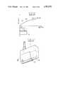
- a coupler Cis mounted on the tip end of a sector-scanning ultrasonic transducer probe 11.
- the coupler Chas a mounting surface 2 which is mounted on the probe 11 and an abutting surface 3 which will be held against an object to be examined.
- the coupler Cis in the shape of a rectangular parallelepiped as a whole and has a height h, a length L in the scanning plane, and a width W in the plane normal to the scanning plane.
- the focusing point P of the lens of the probe 11is closer to the observed region by the height h than focusing point P is when such coupler C is not employed.
- the first problemis that as the coupler height h is increased, the length L and the width W of the coupler are also increased, resulting in a large coupler size which cannot be handled with ease.
- FIG. 10shows the relationship bewteen gains of the probe and coupler heights according to a STC (Sensitivity Time Control) curve for a signal received by the probe.
- STCSignal Transmission Time Control
- a signal received from an observed region by the probeis generally weaker as the region is located more deeply in the body, i.e., as the depth of the region is greater.
- Such a signal level variationis compensated for by employing the STC curve to correct the received signal.
- the interior of the coupleris usually filled with water in which ultrasonic energy is substantially not attenuated.
- couplers C1, C2 having different heights h1, h2, respectivelyare employed, no problem is caused by the coupler C1 of the smaller height h1 as its gain G1 is small, but the larger gain G2 of the coupler C2 of the larger height h2 amplifies multiple reflection in a member positioned on the surface of the coupler C which contacts the living body under examination. Such amplified multiple reflection results in an artifact on the reproduced image, presenting an obstacle to the proper reading of the image. Therefore, the coupler for use with an ultrasonic transducer probe should not be of a large height.
- Japanese Utility Model Laid-Open Publication No. 57-136304discloses, as shown in FIG. 11 of the accompanying drawings, a linear-scanning ultrasonic transducer probe 11' having an ultrasonic wave transmission/reception surface 15 and combined with a converter 12 with an acoustic lens 16 held against the ultrasonic wave transmission/reception surface 15.
- the disclosed arrangementis however capable of only shifting the focusing point for transmitted and received ultrasonic waves, but is not based on any idea of keeping the probe and an examined object spaced a prescribed distance from each other.
- Another object of the present inventionis to provide a coupler for use with an ultrasonic transducer probe, which can be handled well.
- Still another object of the present inventionis to provide a coupler for use with an ultrasonic transducer probe, which can produce images in a large field of view.
- a coupleris adapted to be mounted on an ultrasonic transducer probe for us between the probe and a sample or object under examination to keep them spaced a prescribed distance from each other, the coupler having an acoustic lens in an area through which an ultrasonic signal from the probe passes. Since the acoustic lens is employed in the coupler, the focusing point of a lens of the probe can be shifted to a desired position. Inasmuch as ultrasonic transducer probe and the examined object are spaced the prescribed distance from each other, an observed region can be positioned in a wide field of view on a screen.
- FIG. 1is a perspective view of a coupler for an ultrasonic transducer probe according to the present invention
- FIG. 2is a front elevational view of the coupler shown in FIG. 1;
- FIG. 3is a side elevational view of the coupler of FIG. 1;
- FIG. 4Ais a cross-sectional view of the coupler of FIG. 1;
- FIG. 4Bis a cross-sectional view of a coupler according to another embodiment of the present invention.
- FIG. 4Cis a cross-sectional view of another acoustic lens that can be used in the coupler illustrated in FIG. 4B;
- FIG. 5is a cross-sectional view showing the manner in which the coupler of the invention is used
- FIG. 6is a view explaining the shape of a tip end of the coupler
- FIG. 7is a side elevational view showing the manner in which the coupler of the invention is used in a different way
- FIG. 8is a sectional front elevational view of a conventional coupler
- FIG. 9is a sectional side elevational view of the coupler of FIG. 8;
- FIG. 10is a graph illustrative of a problem of the conventional coupler.
- FIG. 11is a perspective view, partly cut away, of a known coupler.
- a coupler for use with an ultrasonic transducer probe according to the present inventionwill first be described with reference to FIGS. 1 through 3.
- the couplergenerally designated by the reference numeral 1, comprises a main body 1a of a hollow structure having a trapezoid cross section and a mounting member 1b for attachment to the ultrasonic transducer probe.
- the mounting member 1bhas an upper surface serving as a mounting surface 2.
- the main body 1ahas a bottom surface serving as a contact surface 3 for contact with a sample or object such as a human body to be examined.
- the mounting member 1bhas a pair of spaced side walls 2a with inwardly projecting hooks on their upper ends, respectively.
- the ultrasonic transducer probedenoted at 10 has its distal end fitted between and locked by the side walls 2a.
- the contact surface 3In a plane (focusing plane) normal to the direction of the arrow A (FIG. 2) in which an ultrasonic beam is scanned, the contact surface 3 has a width W3 which is smaller than the width 1b of the mounting member W2.
- an acoustic lens 5is mounted at the mounting surface 2.
- the acoustic lens 5has an upper surface 5a having a radius of curvature which is the same as that of an acoustic lens of the probe 10, and a lower surface 5b having a radius of curvature which is smaller than that of the upper surface 5a. Therefore, the acoustic lens 5 has a focusing point P' which is closer toward the probe 10 than the focusing point P of the lens of the probe 10.
- a suitable acoustic dampermay be disposed at each of opposite ends 5c of the acoustic lens 5 to reduce the aperture D for thereby increasing the resolution of a received signal from a shallow region in the object.
- An acoustic coupling agentsuch as ultrasound gel may be disposed between the probe 10 and the acoustic lens 5 for allowing ultrasonic waves to be transmitted smoothly therebetween.
- the contact surface 3 of the coupler 1has a convex curved shape having a certain radius of curvature.
- the radius of curvature of the contact surface 3may be such that an ultrasonic beam B (FIG. 7) emitted from the probe 10 will be applied to the contact surface 3 at a right angle or a substantially right angle at any point thereon since the beam B thus applied can well be transmitted through the contact surface 3 and a reflected beam is reduced in diameter.
- the coupler 1may be constructed as either an outer shell of plastics containing therein an acoustic medium such as water or other solution, or a holder containing a solid colloidal body. Where the acoustic medium such as water or other solution is filled in the outer shell of the coupler 1, the contact surface 3 is composed of a membrane of silicone rubber. The acoustic medium is introduced into the coupler 1 through a inlet 4 (FIGS. 1 and 2).
- the main body 1a of the coupler 1has a height h3 (FIG. 4A) which is smaller than the heights h1, h2 of the conventional couplers C1, C2 (FIG. 10), and a length L2 (FIG. 3) which is also smaller than the length L1 (FIG. 8) of the conventional coupler C.
- h3FIG. 4A
- L2FIG. 3
- the coupler 1 of the inventionmay be smaller in overall size on account of the acoustic lens 5 though the coupler 1 remains functionally the same as the conventional couplers.
- FIG. 4Bshows a coupler according to another embodiment of the present invention.
- the couplerincludes an acoustic lens 5a disposed at a contact side 3 for contact with an object to be examined.
- a membrane 8 of silicone rubberis disposed on a contact surface 2 which is to be held against the ultrasonic transducer probe 10.
- the acoustic lens 5ahas an inner flat surface and an outer convex surface.
- an acoustic lens 5b that can be used in the coupler of FIG. 4Bmay have an inner concave surface and an outer flat surface, as shown in FIG. 4C.
- the coupler 1is used in the following manner:
- a coupler 1 with its focusing point on an observed region 7is selected and mounted on the ultrasonic transducer probe 10. Then, the coupler 1 is held in contact with an object 6 to be examined while ultrasonic waves are being transmitted from the probe 10 toward the object 6 and a reflected ultrasonic beam is being received by the probe 10. While the coupler 1 is thus operated, it is pressed against the surface of the object 6 as shown in FIG. 6, so that the observed region 7 can be viewed directly (pivot scanning).
- the coupler 1thus constructed and operated offers the following advantages:
- the acoustic lens 5is disposed at the mounting surface 2 for attachment to the probe 10, and the radius of curvature of the upper surface 5a of the acoustic lens 5 is the same as that of the acoustic lens of the probe 10 whereas the radius of curvature of the lower surface 5b of the acoustic lens is smaller than that of the upper surface 5a, so that the focusing point P' of the acoustic lens 5 is shifted closer toward the probe 10 than the focusing point of the lens of the probe 10 itself. Therefore, the coupler 5 allows the image of a superficial organ such as a thyroid gland or a carotid artery to be observed with a high image quality at a high resolution and in a wide field of view.
- a superficial organsuch as a thyroid gland or a carotid artery
- the coupler 1does not need to be increased in size, it can be handled easily. As the height h2 of the coupler 1 is made small, any artifact caused by multiple reflection at the contact surface or window member 3 is so reduced that it will not obstruct diagnosis or image reading.
- the freedom in designing the shape of the couplercan be increased greatly.
- the conventional couplersare in the form of a water bag or a pliable solid body such as a colloidal mass, having a flat or freely deformable contact surface for contact with a surface over a target region (i.e., a human body surface). Therefore, if the surface over the target region is flat, then the contact surface 3 is also made flat.
- the bottom surface 3 and opposite side surfaces 31 of the coupler Ccause reflections which are responsible for multiple-reflected images or artifacts on the monitor of an ultrasonic imaging apparatus, resulting in an obstacle to diagnosis or image reading.
- the contact surface 3 of the coupler 1is of a convex curved shape having a prescribed radius of curvature such that the transmittivity of the contact surface 3 with respect to ultrasonic beams is increased whereas reflected beams are weakened. Consequently, multiple reflections on the sides of the coupler 1 are reduced, and hence so are the influence of multiple-reflected images on the monitor of an ultrasonic imaging apparatus, with the result that diagnosis or image reading can smoothly be effected.
- the convex curved contact surface 3allows the coupler 1 to be snugly held in contact with the body surface 6.
- the width W3 of the contact surface 3 in a direction normal to the scanning direction A of the ultrasonic transducer probe 10is smaller than the corresponding width of the contact surface of conventional couplers. This is advantageous in that when the contact surface 3 moves on the body surface 6 as shown in FIG. 5, it is subject to less friction and can be moved smoothly, and when the coupler 1 is angularly moved about a pivot on the body surface 6 as shown in FIG. 6, the contact surface 3 can easily be pressed into the body surface 6 and well be held against the body surface 6.
- both cross-sectional shapes thereof in the scanning direction A and the direction normal theretoare rectangular, and hence the width W1 of the contact surface is relatively large.
- the couplerWhen the coupler is moved on the body surface, it undergoes large friction and cannot be moved smoothly.
- itAt the time of angularly moving the coupler about a pivot on the body surface, it cannot sufficiently be pressed into the body surface and hence its contact with the body surface is poor.
- the coupler of the present inventioncan solve the aforesaid problems of the conventional couplers.
- the present inventionis applicable to not only a coupler for use with a sector-scanning ultrasonic transducer probe, but also a coupler for use with a linear-scanning ultrasonic trandducer probe 11' as shown in FIG. 11.
Landscapes
- Health & Medical Sciences (AREA)
- Life Sciences & Earth Sciences (AREA)
- Physics & Mathematics (AREA)
- Engineering & Computer Science (AREA)
- Acoustics & Sound (AREA)
- Heart & Thoracic Surgery (AREA)
- Animal Behavior & Ethology (AREA)
- Radiology & Medical Imaging (AREA)
- Nuclear Medicine, Radiotherapy & Molecular Imaging (AREA)
- Biomedical Technology (AREA)
- Biophysics (AREA)
- Medical Informatics (AREA)
- Molecular Biology (AREA)
- Surgery (AREA)
- Pathology (AREA)
- General Health & Medical Sciences (AREA)
- Public Health (AREA)
- Veterinary Medicine (AREA)
- Multimedia (AREA)
- Ultra Sonic Daignosis Equipment (AREA)
- Investigating Or Analyzing Materials By The Use Of Ultrasonic Waves (AREA)
- Measurement Of Velocity Or Position Using Acoustic Or Ultrasonic Waves (AREA)
Abstract
Description
Claims (4)
Applications Claiming Priority (2)
| Application Number | Priority Date | Filing Date | Title |
|---|---|---|---|
| JP61-179187 | 1986-07-29 | ||
| JP61179187AJPS6336172A (en) | 1986-07-29 | 1986-07-29 | Ultrasonic coupler |
Publications (1)
| Publication Number | Publication Date |
|---|---|
| US4787070Atrue US4787070A (en) | 1988-11-22 |
Family
ID=16061458
Family Applications (1)
| Application Number | Title | Priority Date | Filing Date |
|---|---|---|---|
| US07/067,124Expired - LifetimeUS4787070A (en) | 1986-07-29 | 1987-06-29 | Coupler for ultrasonic transducer probe |
Country Status (3)
| Country | Link |
|---|---|
| US (1) | US4787070A (en) |
| JP (1) | JPS6336172A (en) |
| DE (1) | DE3722942A1 (en) |
Cited By (77)
| Publication number | Priority date | Publication date | Assignee | Title |
|---|---|---|---|---|
| US4867169A (en)* | 1986-07-29 | 1989-09-19 | Kaoru Machida | Attachment attached to ultrasound probe for clinical application |
| EP0383233A3 (en)* | 1989-02-14 | 1991-11-13 | Kabushiki Kaisha Toshiba | Ultrasonic probe and acoustic lens attachment |
| WO1996025888A1 (en)* | 1995-02-21 | 1996-08-29 | Exogen, Inc. | Gel containment structure |
| US5762616A (en)* | 1996-03-15 | 1998-06-09 | Exogen, Inc. | Apparatus for ultrasonic treatment of sites corresponding to the torso |
| US5904659A (en)* | 1997-02-14 | 1999-05-18 | Exogen, Inc. | Ultrasonic treatment for wounds |
| US6234990B1 (en)* | 1996-06-28 | 2001-05-22 | Sontra Medical, Inc. | Ultrasound enhancement of transdermal transport |
| US6416486B1 (en)* | 1999-03-31 | 2002-07-09 | Ethicon Endo-Surgery, Inc. | Ultrasonic surgical device having an embedding surface and a coagulating surface |
| AU754621B2 (en)* | 1995-02-21 | 2002-11-21 | Exogen, Inc. | Gel containment structure |
| US6500133B2 (en)* | 1999-05-14 | 2002-12-31 | University Of Washington | Apparatus and method for producing high intensity focused ultrasonic energy for medical applications |
| US6585647B1 (en) | 1998-07-21 | 2003-07-01 | Alan A. Winder | Method and means for synthetic structural imaging and volume estimation of biological tissue organs |
| US6666835B2 (en)* | 1999-05-14 | 2003-12-23 | University Of Washington | Self-cooled ultrasonic applicator for medical applications |
| US20040171980A1 (en)* | 1998-12-18 | 2004-09-02 | Sontra Medical, Inc. | Method and apparatus for enhancement of transdermal transport |
| US20040236268A1 (en)* | 1998-01-08 | 2004-11-25 | Sontra Medical, Inc. | Method and apparatus for enhancement of transdermal transport |
| EP1014858A4 (en)* | 1997-08-19 | 2005-07-13 | John D Mendlein | Ultrasonic transmission films and devices, particularly for hygienic transducer surfaces |
| US6932308B2 (en) | 2000-10-25 | 2005-08-23 | Exogen, Inc. | Transducer mounting assembly |
| US7066884B2 (en) | 1998-01-08 | 2006-06-27 | Sontra Medical, Inc. | System, method, and device for non-invasive body fluid sampling and analysis |
| US7108663B2 (en) | 1997-02-06 | 2006-09-19 | Exogen, Inc. | Method and apparatus for cartilage growth stimulation |
| US20070049846A1 (en)* | 2005-08-24 | 2007-03-01 | C.R.Bard, Inc. | Stylet Apparatuses and Methods of Manufacture |
| US7211060B1 (en) | 1998-05-06 | 2007-05-01 | Exogen, Inc. | Ultrasound bandages |
| DE102006012114A1 (en)* | 2006-03-14 | 2007-09-20 | Endress + Hauser Flowtec Ag | Device for determining and / or monitoring the volume or mass flow of a medium in a pipeline |
| US20070232991A1 (en)* | 2006-03-29 | 2007-10-04 | Alcon, Inc. | Surgical system having a non-invasive flow sensor |
| US20070244427A1 (en)* | 2006-03-29 | 2007-10-18 | Nader Nazarifar | Non-invasive flow measurement |
| US7410469B1 (en) | 1999-05-21 | 2008-08-12 | Exogen, Inc. | Apparatus and method for ultrasonically and electromagnetically treating tissue |
| US7429248B1 (en) | 2001-08-09 | 2008-09-30 | Exogen, Inc. | Method and apparatus for controlling acoustic modes in tissue healing applications |
| US7429249B1 (en) | 1999-06-14 | 2008-09-30 | Exogen, Inc. | Method for cavitation-induced tissue healing with low intensity ultrasound |
| US7432069B2 (en) | 2005-12-05 | 2008-10-07 | Sontra Medical Corporation | Biocompatible chemically crosslinked hydrogels for glucose sensing |
| US20090249877A1 (en)* | 2008-04-04 | 2009-10-08 | Vibhu Vivek | Methods and systems for ultrasonic coupling using ultrasonic radiation pressure |
| US20100036227A1 (en)* | 2007-11-26 | 2010-02-11 | C. R. Bard, Inc. | Apparatus and display methods relating to intravascular placement of a catheter |
| US20100094116A1 (en)* | 2008-10-07 | 2010-04-15 | Lucent Medical Systems, Inc. | Percutaneous magnetic gastrostomy |
| US20100204569A1 (en)* | 2007-11-26 | 2010-08-12 | C. R. Bard, Inc. | System for placement of a catheter including a signal-generating stylet |
| US7789841B2 (en) | 1997-02-06 | 2010-09-07 | Exogen, Inc. | Method and apparatus for connective tissue treatment |
| US20100318026A1 (en)* | 2009-06-12 | 2010-12-16 | Romedex International Srl | Devices and Methods for Endovascular Electrography |
| US20100331712A1 (en)* | 2006-10-23 | 2010-12-30 | Bard Access Systems, Inc. | Method of locating the tip of a central venous catheter |
| US20110015533A1 (en)* | 2007-11-26 | 2011-01-20 | C.R. Bard, Inc. | Stylets for use with apparatus for intravascular placement of a catheter |
| US20110196248A1 (en)* | 2009-06-12 | 2011-08-11 | Bard Access Systems, Inc. | Apparatus and method for catheter navigation and tip location |
| US8224414B2 (en) | 2004-10-28 | 2012-07-17 | Echo Therapeutics, Inc. | System and method for analyte sampling and analysis with hydrogel |
| US8386027B2 (en) | 2007-04-27 | 2013-02-26 | Echo Therapeutics, Inc. | Skin permeation device for analyte sensing or transdermal drug delivery |
| US8388541B2 (en) | 2007-11-26 | 2013-03-05 | C. R. Bard, Inc. | Integrated system for intravascular placement of a catheter |
| US8388546B2 (en) | 2006-10-23 | 2013-03-05 | Bard Access Systems, Inc. | Method of locating the tip of a central venous catheter |
| WO2012021542A3 (en)* | 2010-08-09 | 2013-05-23 | C.R. Bard, Inc. | Support and cover structures for an ultrasound probe head |
| US8478382B2 (en) | 2008-02-11 | 2013-07-02 | C. R. Bard, Inc. | Systems and methods for positioning a catheter |
| USD699359S1 (en) | 2011-08-09 | 2014-02-11 | C. R. Bard, Inc. | Ultrasound probe head |
| USD700969S1 (en)* | 2012-11-21 | 2014-03-11 | Samsung Electronics Co., Ltd. | Probe connector for ultrasonic diagnostic equipment |
| US20140180116A1 (en)* | 2009-10-08 | 2014-06-26 | C. R. Bard, Inc. | Coupling Structures for an Ultrasound Probe |
| US8801693B2 (en) | 2010-10-29 | 2014-08-12 | C. R. Bard, Inc. | Bioimpedance-assisted placement of a medical device |
| US8812071B2 (en) | 2007-03-07 | 2014-08-19 | Echo Therapeutics, Inc. | Transdermal analyte monitoring systems and methods for analyte detection |
| USD712043S1 (en)* | 2011-02-08 | 2014-08-26 | Fujifilm Sonosite, Inc. | Ultrasound scanner support |
| USD724745S1 (en)* | 2011-08-09 | 2015-03-17 | C. R. Bard, Inc. | Cap for an ultrasound probe |
| US20150135840A1 (en)* | 2012-08-29 | 2015-05-21 | Thync, Inc. | Systems and devices for coupling ultrasound energy to a body |
| USD732672S1 (en)* | 2014-02-16 | 2015-06-23 | Zetroz, Inc. | Ultrasound applicator |
| US9211107B2 (en) | 2011-11-07 | 2015-12-15 | C. R. Bard, Inc. | Ruggedized ultrasound hydrogel insert |
| US9339206B2 (en) | 2009-06-12 | 2016-05-17 | Bard Access Systems, Inc. | Adaptor for endovascular electrocardiography |
| US9456766B2 (en) | 2007-11-26 | 2016-10-04 | C. R. Bard, Inc. | Apparatus for use with needle insertion guidance system |
| US9492097B2 (en) | 2007-11-26 | 2016-11-15 | C. R. Bard, Inc. | Needle length determination and calibration for insertion guidance system |
| US9521961B2 (en) | 2007-11-26 | 2016-12-20 | C. R. Bard, Inc. | Systems and methods for guiding a medical instrument |
| US9532724B2 (en) | 2009-06-12 | 2017-01-03 | Bard Access Systems, Inc. | Apparatus and method for catheter navigation using endovascular energy mapping |
| US9554716B2 (en) | 2007-11-26 | 2017-01-31 | C. R. Bard, Inc. | Insertion guidance system for needles and medical components |
| US9649048B2 (en) | 2007-11-26 | 2017-05-16 | C. R. Bard, Inc. | Systems and methods for breaching a sterile field for intravascular placement of a catheter |
| US9839372B2 (en) | 2014-02-06 | 2017-12-12 | C. R. Bard, Inc. | Systems and methods for guidance and placement of an intravascular device |
| US20180038509A1 (en)* | 2016-08-02 | 2018-02-08 | Festo Ag & Co. Kg | Valve Actuating System |
| US9901714B2 (en) | 2008-08-22 | 2018-02-27 | C. R. Bard, Inc. | Catheter assembly including ECG sensor and magnetic assemblies |
| US10046139B2 (en) | 2010-08-20 | 2018-08-14 | C. R. Bard, Inc. | Reconfirmation of ECG-assisted catheter tip placement |
| US20190009110A1 (en)* | 2017-07-06 | 2019-01-10 | Slender Medical Ltd. | Ultrasound energy applicator |
| US20190022424A1 (en)* | 2017-07-20 | 2019-01-24 | Korea Institute Of Science And Technology | Focused ultrasound stimulation apparatus using user customized acoustic lens |
| US10349890B2 (en) | 2015-06-26 | 2019-07-16 | C. R. Bard, Inc. | Connector interface for ECG-based catheter positioning system |
| CN110141275A (en)* | 2019-06-13 | 2019-08-20 | 上海交通大学医学院附属第九人民医院 | A Combined Intraoral Soft Tissue Ultrasound Probe |
| US10449330B2 (en) | 2007-11-26 | 2019-10-22 | C. R. Bard, Inc. | Magnetic element-equipped needle assemblies |
| US10524691B2 (en) | 2007-11-26 | 2020-01-07 | C. R. Bard, Inc. | Needle assembly including an aligned magnetic element |
| US10751509B2 (en) | 2007-11-26 | 2020-08-25 | C. R. Bard, Inc. | Iconic representations for guidance of an indwelling medical device |
| US10820885B2 (en) | 2012-06-15 | 2020-11-03 | C. R. Bard, Inc. | Apparatus and methods for detection of a removable cap on an ultrasound probe |
| US10973584B2 (en) | 2015-01-19 | 2021-04-13 | Bard Access Systems, Inc. | Device and method for vascular access |
| US10992079B2 (en) | 2018-10-16 | 2021-04-27 | Bard Access Systems, Inc. | Safety-equipped connection systems and methods thereof for establishing electrical connections |
| US11000207B2 (en) | 2016-01-29 | 2021-05-11 | C. R. Bard, Inc. | Multiple coil system for tracking a medical device |
| US11103213B2 (en) | 2009-10-08 | 2021-08-31 | C. R. Bard, Inc. | Spacers for use with an ultrasound probe |
| US20220160330A1 (en)* | 2020-11-24 | 2022-05-26 | Cal Tenn Innovation, Inc. | Wetting for use in prolonged imaging procedures |
| US20220183658A1 (en)* | 2019-03-29 | 2022-06-16 | Johann Lechner | Shaped gel body, method for producing same, and use thereof |
| US11779304B2 (en)* | 2018-09-21 | 2023-10-10 | Bfly Operations, Inc. | Acoustic damping for ultrasound imaging devices |
Families Citing this family (2)
| Publication number | Priority date | Publication date | Assignee | Title |
|---|---|---|---|---|
| WO1990001902A1 (en)* | 1988-08-30 | 1990-03-08 | Fujitsu Limited | Acoustic coupler |
| JP6650202B2 (en)* | 2015-02-11 | 2020-02-19 | 高周波熱錬株式会社 | Ultrasonic probe for measuring heat treatment layer depth and method for measuring heat treatment layer depth |
Citations (10)
| Publication number | Priority date | Publication date | Assignee | Title |
|---|---|---|---|---|
| US3387604A (en)* | 1965-02-23 | 1968-06-11 | Magnaflux Corp | Focused contact transducer |
| US3934460A (en)* | 1973-08-06 | 1976-01-27 | General Electric Company | Apparatus for focusing and collimating ultrasonic waves |
| US3982223A (en)* | 1972-07-10 | 1976-09-21 | Stanford Research Institute | Composite acoustic lens |
| US4168482A (en)* | 1977-04-04 | 1979-09-18 | The United States Of America As Represented By The Secretary Of The Navy | Combination acoustic filter plate and liquid lens |
| JPS57136304A (en)* | 1982-01-18 | 1982-08-23 | Shinetsu Polymer Co | Pressure sensitive resistance element |
| US4418698A (en)* | 1980-07-29 | 1983-12-06 | Jacques Dory | Ultrasonic scanning probe with mechanical sector scanning means |
| US4435985A (en)* | 1981-04-16 | 1984-03-13 | National Research Development Corporation | Acoustic coupling device |
| US4503861A (en)* | 1983-04-11 | 1985-03-12 | Biomedics, Inc. | Fetal heartbeat doppler transducer |
| US4579123A (en)* | 1983-12-16 | 1986-04-01 | Hewlett-Packard Company | Stand-off device |
| US4603701A (en)* | 1983-12-16 | 1986-08-05 | Hewlett-Packard Company | Stand-off device with special fluid |
Family Cites Families (5)
| Publication number | Priority date | Publication date | Assignee | Title |
|---|---|---|---|---|
| DE938447C (en)* | 1953-02-18 | 1956-02-02 | Zeiss Jena Veb Carl | Process for generating visible ultrasound images |
| GB1539512A (en)* | 1975-01-17 | 1979-01-31 | Greater Glasgow Health Board | Ultrasonic scanning apparatus |
| GB2006434B (en)* | 1977-10-20 | 1982-03-03 | Rca Corp | Switchable depth of focus pulse-echo ultra-sonic imaging display system |
| US4315435A (en)* | 1980-06-30 | 1982-02-16 | Second Foundation | Dual scan ultrasonic scanner |
| JPS57136304U (en)* | 1981-02-23 | 1982-08-25 |
- 1986
- 1986-07-29JPJP61179187Apatent/JPS6336172A/enactivePending
- 1987
- 1987-06-29USUS07/067,124patent/US4787070A/ennot_activeExpired - Lifetime
- 1987-07-10DEDE19873722942patent/DE3722942A1/enactiveGranted
Patent Citations (10)
| Publication number | Priority date | Publication date | Assignee | Title |
|---|---|---|---|---|
| US3387604A (en)* | 1965-02-23 | 1968-06-11 | Magnaflux Corp | Focused contact transducer |
| US3982223A (en)* | 1972-07-10 | 1976-09-21 | Stanford Research Institute | Composite acoustic lens |
| US3934460A (en)* | 1973-08-06 | 1976-01-27 | General Electric Company | Apparatus for focusing and collimating ultrasonic waves |
| US4168482A (en)* | 1977-04-04 | 1979-09-18 | The United States Of America As Represented By The Secretary Of The Navy | Combination acoustic filter plate and liquid lens |
| US4418698A (en)* | 1980-07-29 | 1983-12-06 | Jacques Dory | Ultrasonic scanning probe with mechanical sector scanning means |
| US4435985A (en)* | 1981-04-16 | 1984-03-13 | National Research Development Corporation | Acoustic coupling device |
| JPS57136304A (en)* | 1982-01-18 | 1982-08-23 | Shinetsu Polymer Co | Pressure sensitive resistance element |
| US4503861A (en)* | 1983-04-11 | 1985-03-12 | Biomedics, Inc. | Fetal heartbeat doppler transducer |
| US4579123A (en)* | 1983-12-16 | 1986-04-01 | Hewlett-Packard Company | Stand-off device |
| US4603701A (en)* | 1983-12-16 | 1986-08-05 | Hewlett-Packard Company | Stand-off device with special fluid |
Cited By (146)
| Publication number | Priority date | Publication date | Assignee | Title |
|---|---|---|---|---|
| US4867169A (en)* | 1986-07-29 | 1989-09-19 | Kaoru Machida | Attachment attached to ultrasound probe for clinical application |
| EP0383233A3 (en)* | 1989-02-14 | 1991-11-13 | Kabushiki Kaisha Toshiba | Ultrasonic probe and acoustic lens attachment |
| AU754621B2 (en)* | 1995-02-21 | 2002-11-21 | Exogen, Inc. | Gel containment structure |
| WO1996025888A1 (en)* | 1995-02-21 | 1996-08-29 | Exogen, Inc. | Gel containment structure |
| US5626554A (en)* | 1995-02-21 | 1997-05-06 | Exogen, Inc. | Gel containment structure |
| AU716302B2 (en)* | 1995-02-21 | 2000-02-24 | Exogen, Inc. | Gel containment structure |
| KR100421630B1 (en)* | 1995-02-21 | 2004-05-20 | 엑조겐 인코포레이티드 | Gel sealing structure |
| US5762616A (en)* | 1996-03-15 | 1998-06-09 | Exogen, Inc. | Apparatus for ultrasonic treatment of sites corresponding to the torso |
| US6491657B2 (en) | 1996-06-28 | 2002-12-10 | Sontra Medical, Inc. | Ultrasound enhancement of transdermal transport |
| US6234990B1 (en)* | 1996-06-28 | 2001-05-22 | Sontra Medical, Inc. | Ultrasound enhancement of transdermal transport |
| US7789841B2 (en) | 1997-02-06 | 2010-09-07 | Exogen, Inc. | Method and apparatus for connective tissue treatment |
| US8123707B2 (en) | 1997-02-06 | 2012-02-28 | Exogen, Inc. | Method and apparatus for connective tissue treatment |
| US7108663B2 (en) | 1997-02-06 | 2006-09-19 | Exogen, Inc. | Method and apparatus for cartilage growth stimulation |
| US5904659A (en)* | 1997-02-14 | 1999-05-18 | Exogen, Inc. | Ultrasonic treatment for wounds |
| US6685656B1 (en) | 1997-02-14 | 2004-02-03 | Exogen, Inc. | Ultrasonic treatment for wounds |
| US6190336B1 (en) | 1997-02-14 | 2001-02-20 | Exogen, Inc. | Ultrasonic treatment for wounds |
| US6273864B1 (en) | 1997-02-14 | 2001-08-14 | Exogen, Inc. | Ultrasonic treatment for wounds |
| US7628764B2 (en) | 1997-02-14 | 2009-12-08 | Exogen, Inc. | Ultrasonic treatment for wounds |
| EP1014858A4 (en)* | 1997-08-19 | 2005-07-13 | John D Mendlein | Ultrasonic transmission films and devices, particularly for hygienic transducer surfaces |
| US20040236268A1 (en)* | 1998-01-08 | 2004-11-25 | Sontra Medical, Inc. | Method and apparatus for enhancement of transdermal transport |
| US7066884B2 (en) | 1998-01-08 | 2006-06-27 | Sontra Medical, Inc. | System, method, and device for non-invasive body fluid sampling and analysis |
| US8287483B2 (en) | 1998-01-08 | 2012-10-16 | Echo Therapeutics, Inc. | Method and apparatus for enhancement of transdermal transport |
| US7211060B1 (en) | 1998-05-06 | 2007-05-01 | Exogen, Inc. | Ultrasound bandages |
| US6585647B1 (en) | 1998-07-21 | 2003-07-01 | Alan A. Winder | Method and means for synthetic structural imaging and volume estimation of biological tissue organs |
| US8870810B2 (en) | 1998-12-18 | 2014-10-28 | Echo Therapeutics, Inc. | Method and apparatus for enhancement of transdermal transport |
| US20040171980A1 (en)* | 1998-12-18 | 2004-09-02 | Sontra Medical, Inc. | Method and apparatus for enhancement of transdermal transport |
| US6416486B1 (en)* | 1999-03-31 | 2002-07-09 | Ethicon Endo-Surgery, Inc. | Ultrasonic surgical device having an embedding surface and a coagulating surface |
| US6500133B2 (en)* | 1999-05-14 | 2002-12-31 | University Of Washington | Apparatus and method for producing high intensity focused ultrasonic energy for medical applications |
| US6666835B2 (en)* | 1999-05-14 | 2003-12-23 | University Of Washington | Self-cooled ultrasonic applicator for medical applications |
| US7410469B1 (en) | 1999-05-21 | 2008-08-12 | Exogen, Inc. | Apparatus and method for ultrasonically and electromagnetically treating tissue |
| US7429249B1 (en) | 1999-06-14 | 2008-09-30 | Exogen, Inc. | Method for cavitation-induced tissue healing with low intensity ultrasound |
| US6932308B2 (en) | 2000-10-25 | 2005-08-23 | Exogen, Inc. | Transducer mounting assembly |
| US7429248B1 (en) | 2001-08-09 | 2008-09-30 | Exogen, Inc. | Method and apparatus for controlling acoustic modes in tissue healing applications |
| US8224414B2 (en) | 2004-10-28 | 2012-07-17 | Echo Therapeutics, Inc. | System and method for analyte sampling and analysis with hydrogel |
| US11207496B2 (en) | 2005-08-24 | 2021-12-28 | C. R. Bard, Inc. | Stylet apparatuses and methods of manufacture |
| US20070049846A1 (en)* | 2005-08-24 | 2007-03-01 | C.R.Bard, Inc. | Stylet Apparatuses and Methods of Manufacture |
| US10004875B2 (en) | 2005-08-24 | 2018-06-26 | C. R. Bard, Inc. | Stylet apparatuses and methods of manufacture |
| US8784336B2 (en) | 2005-08-24 | 2014-07-22 | C. R. Bard, Inc. | Stylet apparatuses and methods of manufacture |
| US7432069B2 (en) | 2005-12-05 | 2008-10-07 | Sontra Medical Corporation | Biocompatible chemically crosslinked hydrogels for glucose sensing |
| DE102006012114A1 (en)* | 2006-03-14 | 2007-09-20 | Endress + Hauser Flowtec Ag | Device for determining and / or monitoring the volume or mass flow of a medium in a pipeline |
| US20110023623A1 (en)* | 2006-03-14 | 2011-02-03 | Endress + Hauser Flowtec Ag | Device for Determining and/or Monitoring the Volume or Mass Flow Rate of a Medium in a Pipe Conduit |
| US8047081B2 (en) | 2006-03-14 | 2011-11-01 | Endress + Hauser Flowtec Ag | Flow monitoring apparatus having an ultrasonic sensor with a coupling adapter having securing mechanism |
| US20070232991A1 (en)* | 2006-03-29 | 2007-10-04 | Alcon, Inc. | Surgical system having a non-invasive flow sensor |
| US20070244427A1 (en)* | 2006-03-29 | 2007-10-18 | Nader Nazarifar | Non-invasive flow measurement |
| US8006570B2 (en)* | 2006-03-29 | 2011-08-30 | Alcon, Inc. | Non-invasive flow measurement |
| US8343100B2 (en) | 2006-03-29 | 2013-01-01 | Novartis Ag | Surgical system having a non-invasive flow sensor |
| US20100331712A1 (en)* | 2006-10-23 | 2010-12-30 | Bard Access Systems, Inc. | Method of locating the tip of a central venous catheter |
| US9833169B2 (en) | 2006-10-23 | 2017-12-05 | Bard Access Systems, Inc. | Method of locating the tip of a central venous catheter |
| US9265443B2 (en) | 2006-10-23 | 2016-02-23 | Bard Access Systems, Inc. | Method of locating the tip of a central venous catheter |
| US9345422B2 (en) | 2006-10-23 | 2016-05-24 | Bard Acess Systems, Inc. | Method of locating the tip of a central venous catheter |
| US8858455B2 (en) | 2006-10-23 | 2014-10-14 | Bard Access Systems, Inc. | Method of locating the tip of a central venous catheter |
| US8388546B2 (en) | 2006-10-23 | 2013-03-05 | Bard Access Systems, Inc. | Method of locating the tip of a central venous catheter |
| US8512256B2 (en) | 2006-10-23 | 2013-08-20 | Bard Access Systems, Inc. | Method of locating the tip of a central venous catheter |
| US8774907B2 (en) | 2006-10-23 | 2014-07-08 | Bard Access Systems, Inc. | Method of locating the tip of a central venous catheter |
| US8812071B2 (en) | 2007-03-07 | 2014-08-19 | Echo Therapeutics, Inc. | Transdermal analyte monitoring systems and methods for analyte detection |
| US9572527B2 (en) | 2007-04-27 | 2017-02-21 | Echo Therapeutics, Inc. | Skin permeation device for analyte sensing or transdermal drug delivery |
| US8386027B2 (en) | 2007-04-27 | 2013-02-26 | Echo Therapeutics, Inc. | Skin permeation device for analyte sensing or transdermal drug delivery |
| US10238418B2 (en) | 2007-11-26 | 2019-03-26 | C. R. Bard, Inc. | Apparatus for use with needle insertion guidance system |
| US10449330B2 (en) | 2007-11-26 | 2019-10-22 | C. R. Bard, Inc. | Magnetic element-equipped needle assemblies |
| US11779240B2 (en) | 2007-11-26 | 2023-10-10 | C. R. Bard, Inc. | Systems and methods for breaching a sterile field for intravascular placement of a catheter |
| US11707205B2 (en) | 2007-11-26 | 2023-07-25 | C. R. Bard, Inc. | Integrated system for intravascular placement of a catheter |
| US11529070B2 (en) | 2007-11-26 | 2022-12-20 | C. R. Bard, Inc. | System and methods for guiding a medical instrument |
| US9999371B2 (en) | 2007-11-26 | 2018-06-19 | C. R. Bard, Inc. | Integrated system for intravascular placement of a catheter |
| US8781555B2 (en) | 2007-11-26 | 2014-07-15 | C. R. Bard, Inc. | System for placement of a catheter including a signal-generating stylet |
| US20100204569A1 (en)* | 2007-11-26 | 2010-08-12 | C. R. Bard, Inc. | System for placement of a catheter including a signal-generating stylet |
| US11134915B2 (en) | 2007-11-26 | 2021-10-05 | C. R. Bard, Inc. | System for placement of a catheter including a signal-generating stylet |
| US9681823B2 (en) | 2007-11-26 | 2017-06-20 | C. R. Bard, Inc. | Integrated system for intravascular placement of a catheter |
| US11123099B2 (en) | 2007-11-26 | 2021-09-21 | C. R. Bard, Inc. | Apparatus for use with needle insertion guidance system |
| US8849382B2 (en) | 2007-11-26 | 2014-09-30 | C. R. Bard, Inc. | Apparatus and display methods relating to intravascular placement of a catheter |
| US8388541B2 (en) | 2007-11-26 | 2013-03-05 | C. R. Bard, Inc. | Integrated system for intravascular placement of a catheter |
| US9649048B2 (en) | 2007-11-26 | 2017-05-16 | C. R. Bard, Inc. | Systems and methods for breaching a sterile field for intravascular placement of a catheter |
| US9636031B2 (en) | 2007-11-26 | 2017-05-02 | C.R. Bard, Inc. | Stylets for use with apparatus for intravascular placement of a catheter |
| US9554716B2 (en) | 2007-11-26 | 2017-01-31 | C. R. Bard, Inc. | Insertion guidance system for needles and medical components |
| US10966630B2 (en) | 2007-11-26 | 2021-04-06 | C. R. Bard, Inc. | Integrated system for intravascular placement of a catheter |
| US10849695B2 (en) | 2007-11-26 | 2020-12-01 | C. R. Bard, Inc. | Systems and methods for breaching a sterile field for intravascular placement of a catheter |
| US10751509B2 (en) | 2007-11-26 | 2020-08-25 | C. R. Bard, Inc. | Iconic representations for guidance of an indwelling medical device |
| US10602958B2 (en) | 2007-11-26 | 2020-03-31 | C. R. Bard, Inc. | Systems and methods for guiding a medical instrument |
| US10524691B2 (en) | 2007-11-26 | 2020-01-07 | C. R. Bard, Inc. | Needle assembly including an aligned magnetic element |
| US9549685B2 (en) | 2007-11-26 | 2017-01-24 | C. R. Bard, Inc. | Apparatus and display methods relating to intravascular placement of a catheter |
| US10342575B2 (en) | 2007-11-26 | 2019-07-09 | C. R. Bard, Inc. | Apparatus for use with needle insertion guidance system |
| US20100036227A1 (en)* | 2007-11-26 | 2010-02-11 | C. R. Bard, Inc. | Apparatus and display methods relating to intravascular placement of a catheter |
| US20110015533A1 (en)* | 2007-11-26 | 2011-01-20 | C.R. Bard, Inc. | Stylets for use with apparatus for intravascular placement of a catheter |
| US10231753B2 (en) | 2007-11-26 | 2019-03-19 | C. R. Bard, Inc. | Insertion guidance system for needles and medical components |
| US10165962B2 (en) | 2007-11-26 | 2019-01-01 | C. R. Bard, Inc. | Integrated systems for intravascular placement of a catheter |
| US9456766B2 (en) | 2007-11-26 | 2016-10-04 | C. R. Bard, Inc. | Apparatus for use with needle insertion guidance system |
| US9492097B2 (en) | 2007-11-26 | 2016-11-15 | C. R. Bard, Inc. | Needle length determination and calibration for insertion guidance system |
| US9521961B2 (en) | 2007-11-26 | 2016-12-20 | C. R. Bard, Inc. | Systems and methods for guiding a medical instrument |
| US9526440B2 (en) | 2007-11-26 | 2016-12-27 | C.R. Bard, Inc. | System for placement of a catheter including a signal-generating stylet |
| US10105121B2 (en) | 2007-11-26 | 2018-10-23 | C. R. Bard, Inc. | System for placement of a catheter including a signal-generating stylet |
| US8971994B2 (en) | 2008-02-11 | 2015-03-03 | C. R. Bard, Inc. | Systems and methods for positioning a catheter |
| US8478382B2 (en) | 2008-02-11 | 2013-07-02 | C. R. Bard, Inc. | Systems and methods for positioning a catheter |
| US8127614B2 (en)* | 2008-04-04 | 2012-03-06 | Microsonic Systems Inc. | Methods and systems for ultrasonic coupling using ultrasonic radiation pressure |
| US20090249877A1 (en)* | 2008-04-04 | 2009-10-08 | Vibhu Vivek | Methods and systems for ultrasonic coupling using ultrasonic radiation pressure |
| US9901714B2 (en) | 2008-08-22 | 2018-02-27 | C. R. Bard, Inc. | Catheter assembly including ECG sensor and magnetic assemblies |
| US11027101B2 (en) | 2008-08-22 | 2021-06-08 | C. R. Bard, Inc. | Catheter assembly including ECG sensor and magnetic assemblies |
| US20100094116A1 (en)* | 2008-10-07 | 2010-04-15 | Lucent Medical Systems, Inc. | Percutaneous magnetic gastrostomy |
| US8437833B2 (en) | 2008-10-07 | 2013-05-07 | Bard Access Systems, Inc. | Percutaneous magnetic gastrostomy |
| US9907513B2 (en) | 2008-10-07 | 2018-03-06 | Bard Access Systems, Inc. | Percutaneous magnetic gastrostomy |
| US9339206B2 (en) | 2009-06-12 | 2016-05-17 | Bard Access Systems, Inc. | Adaptor for endovascular electrocardiography |
| US10231643B2 (en) | 2009-06-12 | 2019-03-19 | Bard Access Systems, Inc. | Apparatus and method for catheter navigation and tip location |
| US9125578B2 (en) | 2009-06-12 | 2015-09-08 | Bard Access Systems, Inc. | Apparatus and method for catheter navigation and tip location |
| US20100318026A1 (en)* | 2009-06-12 | 2010-12-16 | Romedex International Srl | Devices and Methods for Endovascular Electrography |
| US20110196248A1 (en)* | 2009-06-12 | 2011-08-11 | Bard Access Systems, Inc. | Apparatus and method for catheter navigation and tip location |
| US9532724B2 (en) | 2009-06-12 | 2017-01-03 | Bard Access Systems, Inc. | Apparatus and method for catheter navigation using endovascular energy mapping |
| US9445734B2 (en) | 2009-06-12 | 2016-09-20 | Bard Access Systems, Inc. | Devices and methods for endovascular electrography |
| US10912488B2 (en) | 2009-06-12 | 2021-02-09 | Bard Access Systems, Inc. | Apparatus and method for catheter navigation and tip location |
| US11419517B2 (en) | 2009-06-12 | 2022-08-23 | Bard Access Systems, Inc. | Apparatus and method for catheter navigation using endovascular energy mapping |
| US10271762B2 (en) | 2009-06-12 | 2019-04-30 | Bard Access Systems, Inc. | Apparatus and method for catheter navigation using endovascular energy mapping |
| US10639008B2 (en) | 2009-10-08 | 2020-05-05 | C. R. Bard, Inc. | Support and cover structures for an ultrasound probe head |
| US11103213B2 (en) | 2009-10-08 | 2021-08-31 | C. R. Bard, Inc. | Spacers for use with an ultrasound probe |
| US20140180116A1 (en)* | 2009-10-08 | 2014-06-26 | C. R. Bard, Inc. | Coupling Structures for an Ultrasound Probe |
| US11998386B2 (en) | 2009-10-08 | 2024-06-04 | C. R. Bard, Inc. | Support and cover structures for an ultrasound probe head |
| CN103228219A (en)* | 2010-08-09 | 2013-07-31 | C·R·巴德股份有限公司 | Support and cover structures for ultrasound probe head |
| CN103228219B (en)* | 2010-08-09 | 2016-04-27 | C·R·巴德股份有限公司 | Support and Covering Structures for Ultrasound Probe Heads |
| WO2012021542A3 (en)* | 2010-08-09 | 2013-05-23 | C.R. Bard, Inc. | Support and cover structures for an ultrasound probe head |
| US10046139B2 (en) | 2010-08-20 | 2018-08-14 | C. R. Bard, Inc. | Reconfirmation of ECG-assisted catheter tip placement |
| US9415188B2 (en) | 2010-10-29 | 2016-08-16 | C. R. Bard, Inc. | Bioimpedance-assisted placement of a medical device |
| US8801693B2 (en) | 2010-10-29 | 2014-08-12 | C. R. Bard, Inc. | Bioimpedance-assisted placement of a medical device |
| USD712043S1 (en)* | 2011-02-08 | 2014-08-26 | Fujifilm Sonosite, Inc. | Ultrasound scanner support |
| USD754357S1 (en) | 2011-08-09 | 2016-04-19 | C. R. Bard, Inc. | Ultrasound probe head |
| USD699359S1 (en) | 2011-08-09 | 2014-02-11 | C. R. Bard, Inc. | Ultrasound probe head |
| USD724745S1 (en)* | 2011-08-09 | 2015-03-17 | C. R. Bard, Inc. | Cap for an ultrasound probe |
| US9211107B2 (en) | 2011-11-07 | 2015-12-15 | C. R. Bard, Inc. | Ruggedized ultrasound hydrogel insert |
| US10820885B2 (en) | 2012-06-15 | 2020-11-03 | C. R. Bard, Inc. | Apparatus and methods for detection of a removable cap on an ultrasound probe |
| US10413757B2 (en)* | 2012-08-29 | 2019-09-17 | Cerevast Medical, Inc. | Systems and devices for coupling ultrasound energy to a body |
| US20150135840A1 (en)* | 2012-08-29 | 2015-05-21 | Thync, Inc. | Systems and devices for coupling ultrasound energy to a body |
| USD700969S1 (en)* | 2012-11-21 | 2014-03-11 | Samsung Electronics Co., Ltd. | Probe connector for ultrasonic diagnostic equipment |
| US10863920B2 (en) | 2014-02-06 | 2020-12-15 | C. R. Bard, Inc. | Systems and methods for guidance and placement of an intravascular device |
| US9839372B2 (en) | 2014-02-06 | 2017-12-12 | C. R. Bard, Inc. | Systems and methods for guidance and placement of an intravascular device |
| USD732672S1 (en)* | 2014-02-16 | 2015-06-23 | Zetroz, Inc. | Ultrasound applicator |
| US10973584B2 (en) | 2015-01-19 | 2021-04-13 | Bard Access Systems, Inc. | Device and method for vascular access |
| US10349890B2 (en) | 2015-06-26 | 2019-07-16 | C. R. Bard, Inc. | Connector interface for ECG-based catheter positioning system |
| US11026630B2 (en) | 2015-06-26 | 2021-06-08 | C. R. Bard, Inc. | Connector interface for ECG-based catheter positioning system |
| US11000207B2 (en) | 2016-01-29 | 2021-05-11 | C. R. Bard, Inc. | Multiple coil system for tracking a medical device |
| US20180038509A1 (en)* | 2016-08-02 | 2018-02-08 | Festo Ag & Co. Kg | Valve Actuating System |
| US10584805B2 (en)* | 2016-08-02 | 2020-03-10 | Festo Ag & Co. Kg | Valve actuating system |
| US20190009110A1 (en)* | 2017-07-06 | 2019-01-10 | Slender Medical Ltd. | Ultrasound energy applicator |
| US20190022424A1 (en)* | 2017-07-20 | 2019-01-24 | Korea Institute Of Science And Technology | Focused ultrasound stimulation apparatus using user customized acoustic lens |
| US11779304B2 (en)* | 2018-09-21 | 2023-10-10 | Bfly Operations, Inc. | Acoustic damping for ultrasound imaging devices |
| US11621518B2 (en) | 2018-10-16 | 2023-04-04 | Bard Access Systems, Inc. | Safety-equipped connection systems and methods thereof for establishing electrical connections |
| US10992079B2 (en) | 2018-10-16 | 2021-04-27 | Bard Access Systems, Inc. | Safety-equipped connection systems and methods thereof for establishing electrical connections |
| US20220183658A1 (en)* | 2019-03-29 | 2022-06-16 | Johann Lechner | Shaped gel body, method for producing same, and use thereof |
| CN110141275A (en)* | 2019-06-13 | 2019-08-20 | 上海交通大学医学院附属第九人民医院 | A Combined Intraoral Soft Tissue Ultrasound Probe |
| CN110141275B (en)* | 2019-06-13 | 2025-05-06 | 上海交通大学医学院附属第九人民医院 | A combined intraoral soft tissue ultrasound probe |
| US20220160330A1 (en)* | 2020-11-24 | 2022-05-26 | Cal Tenn Innovation, Inc. | Wetting for use in prolonged imaging procedures |
| US12127883B2 (en)* | 2020-11-24 | 2024-10-29 | Cal Tenn Innovation, Inc. | Wetting for use in prolonged imaging procedures |
Also Published As
| Publication number | Publication date |
|---|---|
| DE3722942A1 (en) | 1988-02-04 |
| JPS6336172A (en) | 1988-02-16 |
Similar Documents
| Publication | Publication Date | Title |
|---|---|---|
| US4787070A (en) | Coupler for ultrasonic transducer probe | |
| US4867169A (en) | Attachment attached to ultrasound probe for clinical application | |
| US4796632A (en) | Standoff adapter for ultrasound probe | |
| US4794930A (en) | Attachment for diagnostic ultrasound probe | |
| US4130112A (en) | Coupling apparatus for ultrasonic medical diagnostic system | |
| US4084582A (en) | Ultrasonic imaging system | |
| US4977780A (en) | Ultrasonic probe device | |
| US4333474A (en) | Ultrasonic imaging system | |
| US4207901A (en) | Ultrasound reflector | |
| US7307374B2 (en) | Ultrasound transducer | |
| US5127410A (en) | Ultrasound probe and lens assembly for use therein | |
| US5050128A (en) | Ultrasonic probe having an ultrasonic propagation medium | |
| US4248090A (en) | Apparatus for ultrasonically imaging a body | |
| US4246791A (en) | Ultrasonic imaging apparatus | |
| US6261232B1 (en) | Continuous wave transmission/reception type ultrasonic imaging device and ultrasonic probe | |
| US4313444A (en) | Method and apparatus for ultrasonic Doppler detection | |
| JPH0454949A (en) | Ultrasonic inspector | |
| US4612809A (en) | Curved-array ultrasonic probe using low-velocity fluid | |
| GB2099997A (en) | Apparatus for ultrasonic imaging | |
| JPH0810256A (en) | Ultrasonic diagnostic equipment | |
| JP2000201929A (en) | Ultrasonic probe and application thereof | |
| JPS5940845A (en) | Ultrasonic probe | |
| CA1132700A (en) | Apparatus for ultrasonic imaging | |
| JPS61154648A (en) | Ultrasonic probe | |
| JPS63117735A (en) | Ultrasonic probe apparatus |
Legal Events
| Date | Code | Title | Description |
|---|---|---|---|
| AS | Assignment | Owner name:KABUSHIKIGAISHA TOSHIBA, 72, HORIKAWA-CHO, SAIWAI- Free format text:ASSIGNMENT OF ASSIGNORS INTEREST.;ASSIGNORS:SUZUKI, AKIFUMI;SASAKI, HIROSHI;REEL/FRAME:004733/0859 Effective date:19870610 | |
| AS | Assignment | Owner name:KABUSHIKI KAISHA TOSHIBA 72, HORIKAWA-CHO, SAIWAI- Free format text:ASSIGNMENT OF ASSIGNORS INTEREST.;ASSIGNORS:SUZUKI, AKIFUMI;SASAKI, HIROSHI;REEL/FRAME:004929/0574;SIGNING DATES FROM 19880111 TO 19880113 Owner name:KABUSHIKI KAISHA TOSHIBA, A CORP. OF JAPAN, JAPAN Free format text:ASSIGNMENT OF ASSIGNORS INTEREST;ASSIGNORS:SUZUKI, AKIFUMI;SASAKI, HIROSHI;SIGNING DATES FROM 19880111 TO 19880113;REEL/FRAME:004929/0574 | |
| STCF | Information on status: patent grant | Free format text:PATENTED CASE | |
| FEPP | Fee payment procedure | Free format text:PAYOR NUMBER ASSIGNED (ORIGINAL EVENT CODE: ASPN); ENTITY STATUS OF PATENT OWNER: LARGE ENTITY | |
| FEPP | Fee payment procedure | Free format text:PAYOR NUMBER ASSIGNED (ORIGINAL EVENT CODE: ASPN); ENTITY STATUS OF PATENT OWNER: LARGE ENTITY Free format text:PAYER NUMBER DE-ASSIGNED (ORIGINAL EVENT CODE: RMPN); ENTITY STATUS OF PATENT OWNER: LARGE ENTITY | |
| REFU | Refund | Free format text:REFUND OF EXCESS PAYMENTS PROCESSED (ORIGINAL EVENT CODE: R169); ENTITY STATUS OF PATENT OWNER: LARGE ENTITY | |
| FPAY | Fee payment | Year of fee payment:4 | |
| FPAY | Fee payment | Year of fee payment:8 | |
| FPAY | Fee payment | Year of fee payment:12 |