US4786453A - Fiber-matrix composite materials with exactly positioned and oriented fibers and their preparation process - Google Patents
Fiber-matrix composite materials with exactly positioned and oriented fibers and their preparation processDownload PDFInfo
- Publication number
- US4786453A US4786453AUS06/947,379US94737986AUS4786453AUS 4786453 AUS4786453 AUS 4786453AUS 94737986 AUS94737986 AUS 94737986AUS 4786453 AUS4786453 AUS 4786453A
- Authority
- US
- United States
- Prior art keywords
- fibers
- matrix
- brush
- base
- electrostatic field
- Prior art date
- Legal status (The legal status is an assumption and is not a legal conclusion. Google has not performed a legal analysis and makes no representation as to the accuracy of the status listed.)
- Expired - Fee Related
Links
- 239000000835fiberSubstances0.000titleclaimsabstractdescription72
- 239000011159matrix materialSubstances0.000titleclaimsabstractdescription23
- 239000002131composite materialSubstances0.000titleclaimsabstractdescription8
- 238000002360preparation methodMethods0.000titleclaimsabstractdescription4
- 239000000463materialSubstances0.000claimsabstractdescription19
- 238000000034methodMethods0.000claimsabstractdescription16
- 230000005686electrostatic fieldEffects0.000claimsabstractdescription14
- 239000012783reinforcing fiberSubstances0.000claimsabstractdescription12
- 239000007788liquidSubstances0.000claimsabstractdescription6
- 230000006835compressionEffects0.000claimsabstractdescription5
- 238000007906compressionMethods0.000claimsabstractdescription5
- 238000000280densificationMethods0.000claimsabstractdescription3
- 239000007787solidSubstances0.000claims1
- 230000015572biosynthetic processEffects0.000abstractdescription2
- 238000003780insertionMethods0.000abstractdescription2
- 230000037431insertionEffects0.000abstractdescription2
- 238000006116polymerization reactionMethods0.000description5
- 238000004519manufacturing processMethods0.000description4
- 229920005989resinPolymers0.000description4
- 239000011347resinSubstances0.000description4
- OKTJSMMVPCPJKN-UHFFFAOYSA-NCarbonChemical compound[C]OKTJSMMVPCPJKN-UHFFFAOYSA-N0.000description3
- ZOXJGFHDIHLPTG-UHFFFAOYSA-NBoronChemical compound[B]ZOXJGFHDIHLPTG-UHFFFAOYSA-N0.000description2
- 229920000049Carbon (fiber)Polymers0.000description2
- 125000003118aryl groupChemical group0.000description2
- 238000005452bendingMethods0.000description2
- 229910052796boronInorganic materials0.000description2
- 229910052799carbonInorganic materials0.000description2
- 239000004917carbon fiberSubstances0.000description2
- 239000003795chemical substances by applicationSubstances0.000description2
- 230000001419dependent effectEffects0.000description2
- 239000006185dispersionSubstances0.000description2
- 239000011521glassSubstances0.000description2
- 238000005470impregnationMethods0.000description2
- 229920001778nylonPolymers0.000description2
- 239000002904solventSubstances0.000description2
- 239000004677NylonSubstances0.000description1
- 239000004952PolyamideSubstances0.000description1
- XUIMIQQOPSSXEZ-UHFFFAOYSA-NSiliconChemical compound[Si]XUIMIQQOPSSXEZ-UHFFFAOYSA-N0.000description1
- RTAQQCXQSZGOHL-UHFFFAOYSA-NTitaniumChemical compound[Ti]RTAQQCXQSZGOHL-UHFFFAOYSA-N0.000description1
- PNEYBMLMFCGWSK-UHFFFAOYSA-Naluminium oxideInorganic materials[O-2].[O-2].[O-2].[Al+3].[Al+3]PNEYBMLMFCGWSK-UHFFFAOYSA-N0.000description1
- 230000000712assemblyEffects0.000description1
- 238000000429assemblyMethods0.000description1
- CREMABGTGYGIQB-UHFFFAOYSA-Ncarbon carbonChemical compoundC.CCREMABGTGYGIQB-UHFFFAOYSA-N0.000description1
- 239000011203carbon fibre reinforced carbonSubstances0.000description1
- 229920002301cellulose acetatePolymers0.000description1
- 239000000919ceramicSubstances0.000description1
- 239000011248coating agentSubstances0.000description1
- 238000000576coating methodMethods0.000description1
- 238000010924continuous productionMethods0.000description1
- 238000004090dissolutionMethods0.000description1
- 238000009826distributionMethods0.000description1
- 238000005516engineering processMethods0.000description1
- 239000003822epoxy resinSubstances0.000description1
- 238000005530etchingMethods0.000description1
- 239000004744fabricSubstances0.000description1
- 239000000945fillerSubstances0.000description1
- 239000003365glass fiberSubstances0.000description1
- 239000012784inorganic fiberSubstances0.000description1
- 230000003993interactionEffects0.000description1
- 238000009940knittingMethods0.000description1
- 229920002647polyamidePolymers0.000description1
- 229920000647polyepoxidePolymers0.000description1
- 239000000843powderSubstances0.000description1
- 239000002243precursorSubstances0.000description1
- 230000002787reinforcementEffects0.000description1
- 230000009466transformationEffects0.000description1
Images

Classifications
- D—TEXTILES; PAPER
- D04—BRAIDING; LACE-MAKING; KNITTING; TRIMMINGS; NON-WOVEN FABRICS
- D04H—MAKING TEXTILE FABRICS, e.g. FROM FIBRES OR FILAMENTARY MATERIAL; FABRICS MADE BY SUCH PROCESSES OR APPARATUS, e.g. FELTS, NON-WOVEN FABRICS; COTTON-WOOL; WADDING ; NON-WOVEN FABRICS FROM STAPLE FIBRES, FILAMENTS OR YARNS, BONDED WITH AT LEAST ONE WEB-LIKE MATERIAL DURING THEIR CONSOLIDATION
- D04H11/00—Non-woven pile fabrics
- B—PERFORMING OPERATIONS; TRANSPORTING
- B29—WORKING OF PLASTICS; WORKING OF SUBSTANCES IN A PLASTIC STATE IN GENERAL
- B29C—SHAPING OR JOINING OF PLASTICS; SHAPING OF MATERIAL IN A PLASTIC STATE, NOT OTHERWISE PROVIDED FOR; AFTER-TREATMENT OF THE SHAPED PRODUCTS, e.g. REPAIRING
- B29C70/00—Shaping composites, i.e. plastics material comprising reinforcements, fillers or preformed parts, e.g. inserts
- B29C70/04—Shaping composites, i.e. plastics material comprising reinforcements, fillers or preformed parts, e.g. inserts comprising reinforcements only, e.g. self-reinforcing plastics
- B29C70/06—Fibrous reinforcements only
- B29C70/10—Fibrous reinforcements only characterised by the structure of fibrous reinforcements, e.g. hollow fibres
- B29C70/12—Fibrous reinforcements only characterised by the structure of fibrous reinforcements, e.g. hollow fibres using fibres of short length, e.g. in the form of a mat
- B29C70/14—Fibrous reinforcements only characterised by the structure of fibrous reinforcements, e.g. hollow fibres using fibres of short length, e.g. in the form of a mat oriented
- B—PERFORMING OPERATIONS; TRANSPORTING
- B29—WORKING OF PLASTICS; WORKING OF SUBSTANCES IN A PLASTIC STATE IN GENERAL
- B29C—SHAPING OR JOINING OF PLASTICS; SHAPING OF MATERIAL IN A PLASTIC STATE, NOT OTHERWISE PROVIDED FOR; AFTER-TREATMENT OF THE SHAPED PRODUCTS, e.g. REPAIRING
- B29C70/00—Shaping composites, i.e. plastics material comprising reinforcements, fillers or preformed parts, e.g. inserts
- B29C70/04—Shaping composites, i.e. plastics material comprising reinforcements, fillers or preformed parts, e.g. inserts comprising reinforcements only, e.g. self-reinforcing plastics
- B29C70/06—Fibrous reinforcements only
- B29C70/10—Fibrous reinforcements only characterised by the structure of fibrous reinforcements, e.g. hollow fibres
- B29C70/16—Fibrous reinforcements only characterised by the structure of fibrous reinforcements, e.g. hollow fibres using fibres of substantial or continuous length
- B29C70/24—Fibrous reinforcements only characterised by the structure of fibrous reinforcements, e.g. hollow fibres using fibres of substantial or continuous length oriented in at least three directions forming a three dimensional structure
- D—TEXTILES; PAPER
- D04—BRAIDING; LACE-MAKING; KNITTING; TRIMMINGS; NON-WOVEN FABRICS
- D04H—MAKING TEXTILE FABRICS, e.g. FROM FIBRES OR FILAMENTARY MATERIAL; FABRICS MADE BY SUCH PROCESSES OR APPARATUS, e.g. FELTS, NON-WOVEN FABRICS; COTTON-WOOL; WADDING ; NON-WOVEN FABRICS FROM STAPLE FIBRES, FILAMENTS OR YARNS, BONDED WITH AT LEAST ONE WEB-LIKE MATERIAL DURING THEIR CONSOLIDATION
- D04H11/00—Non-woven pile fabrics
- D04H11/04—Non-woven pile fabrics formed by zig-zag folding of a fleece or layer of staple fibres, filaments, or yarns, strengthened or consolidated at the folds
- D—TEXTILES; PAPER
- D04—BRAIDING; LACE-MAKING; KNITTING; TRIMMINGS; NON-WOVEN FABRICS
- D04H—MAKING TEXTILE FABRICS, e.g. FROM FIBRES OR FILAMENTARY MATERIAL; FABRICS MADE BY SUCH PROCESSES OR APPARATUS, e.g. FELTS, NON-WOVEN FABRICS; COTTON-WOOL; WADDING ; NON-WOVEN FABRICS FROM STAPLE FIBRES, FILAMENTS OR YARNS, BONDED WITH AT LEAST ONE WEB-LIKE MATERIAL DURING THEIR CONSOLIDATION
- D04H3/00—Non-woven fabrics formed wholly or mainly of yarns or like filamentary material of substantial length
- D04H3/02—Non-woven fabrics formed wholly or mainly of yarns or like filamentary material of substantial length characterised by the method of forming fleeces or layers, e.g. reorientation of yarns or filaments
- D04H3/07—Non-woven fabrics formed wholly or mainly of yarns or like filamentary material of substantial length characterised by the method of forming fleeces or layers, e.g. reorientation of yarns or filaments otherwise than in a plane, e.g. in a tubular way
Definitions
- the present inventionrelates to new fiber-matrix composite materials with exactly positioned and oriented fibers; the invention further relates to a process for preparing said materials.
- composite materialsare, for the most part, constituted of reinforcing fibers dispersed in a suitable matrix;
- the reinforcing fibers which are usedare organic or inorganic fibers such as Nylon fibers (aromatic or non-aromatic), carbon fibers, glass-fibers, silicium carbide fibers, boron fibers, etc.
- the matrices usedare also of organic or inorganic nature, such as for example resin.
- these matricescan contain various fillers such as for example: graphite powder, titanium powder, ceramic powder, etc.
- the materials according to the inventioncontain fibers and matrices such as described hereinabove.
- Composite materialsmay be mono-, bi- or tri-dimensional in their properties, depending on the orientation or orientations of the fibers.
- the inventiontherefore relates to an n-directional composite material, n being at least equal to 3, which is characterized by an accurately controlled positioning and orientation of the fibers in each of said n directions.
- the inventionalso relates to a process for preparing the material according to the invention, which process consists in:
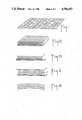
- FIGS. 1 to 12illustrate diagrammatically the different steps of the process.
- the first step of the process according to the inventiontherefore consists in producing a convex brush of equally distributed fibers, said fibers being in a stretched condition, regularly spaced out and secured in position; one preferential embodiment of this first step is illustrated in FIGS. 1 to 5.
- a mono-directional assembly of fibers(glass; polyamide, carbon, alumina, boron or like fibers), being in the form of a plate such as shown in FIG. 1, is used as starting product.
- Said mono-directional fiber structureis then folded (automatically, for example) as illustrated in FIG. 2; it will be noted that the number and the disposition (more or less close together) of the fibers which will form the "brush", will be dependent on the aforesaid folding operation; indeed, the number of fibers will be the greater that the folding is tighter; the folds are thereafter fixed in position by placing along one edge of the folded material a supple strip, for example of cellulose acetate, as illustrated in FIG. 3 (on said FIGURE, said strip is referenced 1 and the folded structure 2).
- a kind of brushshown as 3 in FIG. 4.
- Said brushis placed in a high tension D.C. electrostatic field, for example between 50,000 and 200,000 volts between electrodes 4 and 5.
- the electrostatic fieldstretches the fibers and keeps them at equal distance from one another.
- a productwhich is the same as that used for producing the base 1 in FIG. 3, is sprayed over the brush. This coating operation will use a product which can be subsequently dissolved and destroyed.
- the brushthen obtained, and which is made up of fibers held, by one of their ends (1), parallel together, and in a position perpendicular to the base (or strip 1) due to the use of the electrostatic field, is convex.
- Thisis an extremely important operation in the course of the present invention since, as a result of it, a convex brush is obtained in which the bristles are, on the one hand, sufficiently dense (at their base), but on the other hand, sufficiently spaced out (at their free end) to allow the operations to follow according to the invention.
- the convex brushis diagrammatically shown in FIG. 5.
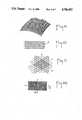
- FIGS. 6 to 9The second step in the process according to the invention is illustrated in FIGS. 6 to 9; it consists in successively placing a number of grids (having the same convexity as the brush) between the fibers of the brush.
- fibersor fibrils
- FIG. 6fibers (or fibrils) are stretched on a frame 7 in order to form a grid; said frame has a predetermined curvature of radius r, the same radius as the brush.
- the fibers laid on said frameare stretched but movable, so as to be moved closer together in the direction of arrows 8.
- Said frameis thereafter fitted over the brush shown in FIG. 5, the result being a bi-dimensional assembly in the warp direction and in the vertical direction, as shown in FIG. 7.
- the described curvaturemakes it easier to introduce the vertical fibers in the warps and the wefts.
- each gridcan be different from the other, either by the number of fibers used (for example, it is possible in certain grids, to take off one fiber out of two), or if necessary even, by the nature of the fibers used; it is finally possible to produce a non-homogeneous material, for example by stacking over a certain thickness, grids in which the fibers are oriented in the same direction, and over another thickness, grids in which the fibers are alternately oriented in two perpendicular directions.
- the followingillustrates one particular embodiment of the invention applied to the preparation of a material having a tri-dimensional orientation, i.e. a material constituted of mono-directional fibers in a plane X or warp, and of a lattice of fibers in a plane Y or weft, with other fibers (called brush) forming an angle of 90° with the warp and with the weft in a plane Z.
- a material having a tri-dimensional orientationi.e. a material constituted of mono-directional fibers in a plane X or warp, and of a lattice of fibers in a plane Y or weft, with other fibers (called brush) forming an angle of 90° with the warp and with the weft in a plane Z.
- the third step according to the inventionconsists in removing the products used, on the one hand for making up the base of the brush, and on the other hand, for fixing the fibers of the brush.
- This removing operationis advantageously carried out (if the materials involved permit it) by simple dissolution with a solvent; the selected solvent is also used for clearing the surface of the fibers so as to facilitate subsequent interactions between fibers and matrix.
- the network of fibersis then dried and the matrix-forming liquid is introduced therein.
- said liquidmay be, depending on the case, either the matrix material in molten state, or a material (such as prepolymer) which, by subsequent transformation, will produce the matrix. This type of impregnation operation is well known of to any one skilled in the art.
- the frames holding the fibers of various gridsare detached, and the resulting structure is laid flat or shaped as necessary; any excess of matrix (or of matrix precursor) can then be removed.
- This particular operationreally gives a tri-dimensional structure X, Y, Z such as illustrated in FIG. 11.
- a carbon matrixcan be introduced in the form of pitch in pure state and after compression and polymerization of the assembly in vacuo in an autoclave, a well known carbon-carbon type structure such as those widely used in aerospace technology and in medical prostheses, is obtained.
- a platehas been produced of dimension 150 ⁇ 100 ⁇ 16 mm, with:
- Ciba-Geigy refa tri-component Ciba-Geigy ref:
- fibers-matrix distribution73% fibers, 27% resin.
- the resulting platewas put through breaking stresses under bending forces of 1600 Gp, in the three axes without any deformation being noted.
- the material finally obtainedmay be shaped or subsequently machined for producing special high resistance parts.
Landscapes
- Engineering & Computer Science (AREA)
- Textile Engineering (AREA)
- Chemical & Material Sciences (AREA)
- Composite Materials (AREA)
- Mechanical Engineering (AREA)
- Nonwoven Fabrics (AREA)
- Manufacture Of Alloys Or Alloy Compounds (AREA)
- Reinforced Plastic Materials (AREA)
- Preliminary Treatment Of Fibers (AREA)
- Macromolecular Compounds Obtained By Forming Nitrogen-Containing Linkages In General (AREA)
- Chemical Or Physical Treatment Of Fibers (AREA)
Abstract
Description
Claims (2)
Applications Claiming Priority (2)
| Application Number | Priority Date | Filing Date | Title |
|---|---|---|---|
| FR8519436AFR2592404B1 (en) | 1985-12-30 | 1985-12-30 | NOVEL COMPOSITE MATERIALS FIBER-MATRIX WITH STRICTLY POSITIONED AND ORIENTED FIBERS AND THEIR PREPARATION METHOD. |
| FR8519436 | 1985-12-30 |
Publications (1)
| Publication Number | Publication Date |
|---|---|
| US4786453Atrue US4786453A (en) | 1988-11-22 |
Family
ID=9326323
Family Applications (1)
| Application Number | Title | Priority Date | Filing Date |
|---|---|---|---|
| US06/947,379Expired - Fee RelatedUS4786453A (en) | 1985-12-30 | 1986-12-29 | Fiber-matrix composite materials with exactly positioned and oriented fibers and their preparation process |
Country Status (15)
| Country | Link |
|---|---|
| US (1) | US4786453A (en) |
| EP (1) | EP0233430B1 (en) |
| JP (1) | JPS62177272A (en) |
| AT (1) | ATE52287T1 (en) |
| AU (1) | AU592844B2 (en) |
| BR (1) | BR8606491A (en) |
| CA (1) | CA1275234C (en) |
| DE (1) | DE3670658D1 (en) |
| DK (1) | DK160887C (en) |
| ES (1) | ES2015889B3 (en) |
| FR (1) | FR2592404B1 (en) |
| GR (1) | GR3000497T3 (en) |
| IE (1) | IE59876B1 (en) |
| PT (1) | PT84030B (en) |
| ZA (1) | ZA869751B (en) |
Cited By (9)
| Publication number | Priority date | Publication date | Assignee | Title |
|---|---|---|---|---|
| EP0352770A3 (en)* | 1988-07-29 | 1991-06-12 | Mitsubishi Rayon Co., Ltd. | Method for manufacturing laminate |
| US5599576A (en)* | 1995-02-06 | 1997-02-04 | Surface Solutions Laboratories, Inc. | Medical apparatus with scratch-resistant coating and method of making same |
| EP0851142A1 (en)* | 1996-12-24 | 1998-07-01 | Dsm N.V. | Structural spring of fibre-reinforced plastic |
| USD512536S1 (en)* | 2003-04-17 | 2005-12-06 | Southwest Agri-Plastics, Inc. | Nest pad |
| US20120135219A1 (en)* | 2009-06-12 | 2012-05-31 | Quickstep Technologies Pty Ltd | Method of producing advanced composite components |
| US10044050B2 (en)* | 2012-07-20 | 2018-08-07 | Carl Freudenberg Kg | Electrically conductive sheet material |
| USD1009388S1 (en)* | 2023-06-08 | 2023-12-26 | Xian Wu | Cat scat mat |
| USD1025515S1 (en)* | 2024-01-16 | 2024-04-30 | Yincong Xiao | Anti-cat sting pad |
| USD1033765S1 (en)* | 2023-09-16 | 2024-07-02 | Yiwu Beixin Technology Co., Ltd. | Animal deterrent mat |
Families Citing this family (9)
| Publication number | Priority date | Publication date | Assignee | Title |
|---|---|---|---|---|
| US4721645A (en)* | 1986-12-22 | 1988-01-26 | General Electric Company | Material for four directional reinforcement of conical shaped object, method for fabricating same and object formed therewith |
| FR2636683B2 (en)* | 1988-02-26 | 1990-12-28 | Berger Michel | HANGING ASSEMBLY SYSTEM HAVING HANGING ELEMENTS FORMED BY CURVILINE RIBS PROVIDED WITH ELASTICALLY DEFORMABLE LIPS |
| JPH02127555A (en)* | 1988-10-31 | 1990-05-16 | Polymer Processing Res Inst | Multi-layered three-dimensional non-woven fabric and production thereof and apparatus therefor |
| US5788804A (en)* | 1995-07-17 | 1998-08-04 | Liba Maschinenfabrik Gmbh | Machine for the production of pre-ready made reinforcement formations |
| DE19624912C2 (en)* | 1995-07-17 | 2002-07-11 | Liba Maschf | Machine for the production of prefabricated reinforcement fabrics |
| FR2920025B1 (en)* | 2007-08-14 | 2010-03-12 | Saertex France | METHOD OF MAKING AN ARMATURE WITH A 3D STRUCTURE FOR COMPOSITE MATERIAL, ARMATURE OBTAINED |
| CN105984138B (en)* | 2015-01-27 | 2019-01-11 | 常州市东科电子科技有限公司 | A kind of dress ornament single face-formed method and 3D printing device |
| CN105984134B (en)* | 2015-01-27 | 2019-05-10 | 常州市东科电子科技有限公司 | A kind of 3D printing device and implementation method manufacturing fleece lined goods |
| CN112721230B (en)* | 2020-11-16 | 2022-03-25 | 浙江大学 | Microfiber high-energy implantation equipment for manufacturing three-dimensional reinforced carbon fiber composite material |
Citations (13)
| Publication number | Priority date | Publication date | Assignee | Title |
|---|---|---|---|---|
| US2152077A (en)* | 1935-02-06 | 1939-03-28 | Behr Manning Corp | Production of piled surfaces in pattern form |
| US3322868A (en)* | 1963-07-02 | 1967-05-30 | Douglas Aircraft Co Inc | Three dimensional reinforced structure |
| FR1491708A (en)* | 1965-09-01 | 1967-08-11 | Iws Nominee Co Ltd | Manufacturing process for composite pile fabrics |
| US3513297A (en)* | 1967-05-31 | 1970-05-19 | Gulton Ind Inc | Heat radiating articles |
| US3515622A (en)* | 1967-09-19 | 1970-06-02 | Outside Carpets Inc | Laminated carpet or mat |
| US3664909A (en)* | 1970-03-25 | 1972-05-23 | Ppg Industries Inc | Needled resin fibrous article |
| US3850723A (en)* | 1971-09-20 | 1974-11-26 | Ppg Industries Inc | Method of making a stampable reinforced sheet |
| US3889035A (en)* | 1972-11-27 | 1975-06-10 | Marling Ind Limited | Fiber-reinforced plastic articles |
| US3900651A (en)* | 1972-11-11 | 1975-08-19 | Bayer Ag | Heavy duty sandwich element |
| US3951718A (en)* | 1975-01-03 | 1976-04-20 | Mcdonnell Douglas Corporation | Method for producing reinforced insulating foam |
| US4132580A (en)* | 1973-10-04 | 1979-01-02 | The English Card Clothing Company Limited | Method of making card clothing with a reinforcing back |
| US4164599A (en)* | 1977-07-25 | 1979-08-14 | Milton Kessler | Weather strip and method of its manufacture |
| US4427221A (en)* | 1981-10-13 | 1984-01-24 | Reed Rock Bit Company | Drill bit nozzle retention and alignment system |
Family Cites Families (4)
| Publication number | Priority date | Publication date | Assignee | Title |
|---|---|---|---|---|
| LU36792A1 (en)* | 1958-11-18 | L A Chaignaud Ets | ||
| FR1475068A (en)* | 1965-03-05 | 1967-03-31 | Debron Carpets Ltd | Improvements relating to pile fabrics |
| ZA72328B (en)* | 1971-01-22 | 1972-09-27 | Dunlop Ltd | Pile coated sheet material |
| FR2509706A1 (en)* | 1981-07-16 | 1983-01-21 | Commissariat Energie Atomique | METHOD FOR IMPLANTING PICOTS ON A CHUCK AND MACHINE FOR CARRYING OUT SAID METHOD |
- 1985
- 1985-12-30FRFR8519436Apatent/FR2592404B1/ennot_activeExpired
- 1986
- 1986-12-24ESES86402931Tpatent/ES2015889B3/ennot_activeExpired - Lifetime
- 1986-12-24DEDE8686402931Tpatent/DE3670658D1/ennot_activeExpired - Fee Related
- 1986-12-24EPEP86402931Apatent/EP0233430B1/ennot_activeExpired - Lifetime
- 1986-12-24ATAT86402931Tpatent/ATE52287T1/ennot_activeIP Right Cessation
- 1986-12-26JPJP61308953Apatent/JPS62177272A/enactivePending
- 1986-12-29PTPT84030Apatent/PT84030B/enunknown
- 1986-12-29USUS06/947,379patent/US4786453A/ennot_activeExpired - Fee Related
- 1986-12-30CACA000526491Apatent/CA1275234C/ennot_activeExpired - Fee Related
- 1986-12-30BRBR8606491Apatent/BR8606491A/ennot_activeIP Right Cessation
- 1986-12-30IEIE340686Apatent/IE59876B1/ennot_activeIP Right Cessation
- 1986-12-30AUAU67066/86Apatent/AU592844B2/ennot_activeCeased
- 1986-12-30ZAZA869751Apatent/ZA869751B/enunknown
- 1986-12-30DKDK634786Apatent/DK160887C/enactive
- 1990
- 1990-05-23GRGR90400319Tpatent/GR3000497T3/enunknown
Patent Citations (13)
| Publication number | Priority date | Publication date | Assignee | Title |
|---|---|---|---|---|
| US2152077A (en)* | 1935-02-06 | 1939-03-28 | Behr Manning Corp | Production of piled surfaces in pattern form |
| US3322868A (en)* | 1963-07-02 | 1967-05-30 | Douglas Aircraft Co Inc | Three dimensional reinforced structure |
| FR1491708A (en)* | 1965-09-01 | 1967-08-11 | Iws Nominee Co Ltd | Manufacturing process for composite pile fabrics |
| US3513297A (en)* | 1967-05-31 | 1970-05-19 | Gulton Ind Inc | Heat radiating articles |
| US3515622A (en)* | 1967-09-19 | 1970-06-02 | Outside Carpets Inc | Laminated carpet or mat |
| US3664909A (en)* | 1970-03-25 | 1972-05-23 | Ppg Industries Inc | Needled resin fibrous article |
| US3850723A (en)* | 1971-09-20 | 1974-11-26 | Ppg Industries Inc | Method of making a stampable reinforced sheet |
| US3900651A (en)* | 1972-11-11 | 1975-08-19 | Bayer Ag | Heavy duty sandwich element |
| US3889035A (en)* | 1972-11-27 | 1975-06-10 | Marling Ind Limited | Fiber-reinforced plastic articles |
| US4132580A (en)* | 1973-10-04 | 1979-01-02 | The English Card Clothing Company Limited | Method of making card clothing with a reinforcing back |
| US3951718A (en)* | 1975-01-03 | 1976-04-20 | Mcdonnell Douglas Corporation | Method for producing reinforced insulating foam |
| US4164599A (en)* | 1977-07-25 | 1979-08-14 | Milton Kessler | Weather strip and method of its manufacture |
| US4427221A (en)* | 1981-10-13 | 1984-01-24 | Reed Rock Bit Company | Drill bit nozzle retention and alignment system |
Cited By (12)
| Publication number | Priority date | Publication date | Assignee | Title |
|---|---|---|---|---|
| EP0352770A3 (en)* | 1988-07-29 | 1991-06-12 | Mitsubishi Rayon Co., Ltd. | Method for manufacturing laminate |
| US5143569A (en)* | 1988-07-29 | 1992-09-01 | Mitsubishi Rayon Co., Ltd. | Method for manufacturing a three dimensional laminate from double pile fabrics |
| US5599576A (en)* | 1995-02-06 | 1997-02-04 | Surface Solutions Laboratories, Inc. | Medical apparatus with scratch-resistant coating and method of making same |
| US5766158A (en)* | 1995-02-06 | 1998-06-16 | Surface Solutions Laboratories, Inc. | Medical apparatus with scratch-resistant coating and method of making same |
| EP0851142A1 (en)* | 1996-12-24 | 1998-07-01 | Dsm N.V. | Structural spring of fibre-reinforced plastic |
| BE1010823A3 (en)* | 1996-12-24 | 1999-02-02 | Dsm Nv | CONSTRUCTION FEATHER prepreg. |
| USD512536S1 (en)* | 2003-04-17 | 2005-12-06 | Southwest Agri-Plastics, Inc. | Nest pad |
| US20120135219A1 (en)* | 2009-06-12 | 2012-05-31 | Quickstep Technologies Pty Ltd | Method of producing advanced composite components |
| US10044050B2 (en)* | 2012-07-20 | 2018-08-07 | Carl Freudenberg Kg | Electrically conductive sheet material |
| USD1009388S1 (en)* | 2023-06-08 | 2023-12-26 | Xian Wu | Cat scat mat |
| USD1033765S1 (en)* | 2023-09-16 | 2024-07-02 | Yiwu Beixin Technology Co., Ltd. | Animal deterrent mat |
| USD1025515S1 (en)* | 2024-01-16 | 2024-04-30 | Yincong Xiao | Anti-cat sting pad |
Also Published As
| Publication number | Publication date |
|---|---|
| ATE52287T1 (en) | 1990-05-15 |
| GR3000497T3 (en) | 1991-06-28 |
| IE863406L (en) | 1987-06-30 |
| ES2015889B3 (en) | 1990-09-16 |
| ZA869751B (en) | 1987-09-30 |
| BR8606491A (en) | 1987-10-20 |
| JPS62177272A (en) | 1987-08-04 |
| AU592844B2 (en) | 1990-01-25 |
| AU6706686A (en) | 1987-07-02 |
| DK634786D0 (en) | 1986-12-30 |
| EP0233430A1 (en) | 1987-08-26 |
| PT84030B (en) | 1989-07-31 |
| DK634786A (en) | 1987-07-01 |
| DK160887C (en) | 1991-10-14 |
| DK160887B (en) | 1991-04-29 |
| IE59876B1 (en) | 1994-04-20 |
| DE3670658D1 (en) | 1990-05-31 |
| PT84030A (en) | 1987-01-01 |
| EP0233430B1 (en) | 1990-04-25 |
| CA1275234C (en) | 1990-10-16 |
| FR2592404B1 (en) | 1989-06-09 |
| FR2592404A1 (en) | 1987-07-03 |
Similar Documents
| Publication | Publication Date | Title |
|---|---|---|
| US4786453A (en) | Fiber-matrix composite materials with exactly positioned and oriented fibers and their preparation process | |
| DE2932201C2 (en) | ||
| US4001478A (en) | Three-dimensional fabric material | |
| US5888609A (en) | Planar porous composite structure and method for its manufacture | |
| US4983451A (en) | Carbon fiber-reinforced carbon composite material and process for producing the same | |
| US3657061A (en) | Reinforced carbon and graphite bodies | |
| US3955602A (en) | Apparatus for fabricating three-dimensional fabric material | |
| JP3371016B2 (en) | Honeycomb structure of heat-resistant structural composite material and method of manufacturing the same | |
| US3994762A (en) | Carbon fiber composites | |
| DE69607056T2 (en) | Fiber reinforced ceramic composite material and method for its production | |
| US5589115A (en) | Method for making fiber-reinforced ceramic matrix composite | |
| US4759977A (en) | Flexible carbon material | |
| CA2174771A1 (en) | Three-dimensional fabric and method for producing | |
| DE3882452T2 (en) | Process for the manufacture of articles from carbon / carbon fibers. | |
| DE69003499T2 (en) | DEFORMABLE TEXTILE STRUCTURE. | |
| DE69418253T2 (en) | A process for producing a composite element containing a fiber reinforcement obtained by liquid | |
| DE69033221T2 (en) | Carbon fibers with non-round cross-section, process for their production and composite material produced therewith | |
| US4221622A (en) | Method of obtaining fibre substrates intended for the production of composite bodies | |
| EP0280233B1 (en) | Method for producing carbon-carbon composite materials | |
| DE69109918T2 (en) | Process for consolidating a fibrous reinforcing structure for the production of a composite part. | |
| EP0439274A1 (en) | Deformable fabric for composite materials | |
| US4546032A (en) | Fiber reinforced carbon/carbon composite structure with tailored directional shear strength properties | |
| DE102004039505A1 (en) | Controlled-thermal-expansion layer system with very diverse uses, formed from composite of polymers and knitted fibrous materials, has adjustable thermal expansion in x, y and z layers | |
| EP0652821B1 (en) | Planar porous composite structure and method for its manufacture | |
| JPH04826B2 (en) |
Legal Events
| Date | Code | Title | Description |
|---|---|---|---|
| AS | Assignment | Owner name:SOCIETE DE DROIT ANGLAIS : PRADOM LIMITED - NATION Free format text:ASSIGNMENT OF ASSIGNORS INTEREST.;ASSIGNOR:BERGER, MICHEL;REEL/FRAME:004668/0090 Effective date:19861222 Owner name:SOCIETE DE DROIT ANGLAIS : PRADOM LIMITED - NATION Free format text:ASSIGNMENT OF ASSIGNORS INTEREST;ASSIGNOR:BERGER, MICHEL;REEL/FRAME:004668/0090 Effective date:19861222 Owner name:SOCIETE DE DROIT ANGLAIS : PRADOM LIMITED, ENGLAND Free format text:ASSIGNMENT OF ASSIGNORS INTEREST;ASSIGNOR:BERGER, MICHEL;REEL/FRAME:004668/0090 Effective date:19861222 | |
| FEPP | Fee payment procedure | Free format text:PAT HOLDER CLAIMS SMALL ENTITY STATUS - SMALL BUSINESS (ORIGINAL EVENT CODE: SM02); ENTITY STATUS OF PATENT OWNER: SMALL ENTITY Free format text:PAYOR NUMBER ASSIGNED (ORIGINAL EVENT CODE: ASPN); ENTITY STATUS OF PATENT OWNER: SMALL ENTITY | |
| FPAY | Fee payment | Year of fee payment:4 | |
| REMI | Maintenance fee reminder mailed | ||
| LAPS | Lapse for failure to pay maintenance fees | ||
| FP | Lapsed due to failure to pay maintenance fee | Effective date:20001122 | |
| STCH | Information on status: patent discontinuation | Free format text:PATENT EXPIRED DUE TO NONPAYMENT OF MAINTENANCE FEES UNDER 37 CFR 1.362 |