US4786225A - Stand-off fastener - Google Patents
Stand-off fastenerDownload PDFInfo
- Publication number
- US4786225A US4786225AUS07/150,441US15044188AUS4786225AUS 4786225 AUS4786225 AUS 4786225AUS 15044188 AUS15044188 AUS 15044188AUS 4786225 AUS4786225 AUS 4786225A
- Authority
- US
- United States
- Prior art keywords
- plunger
- fastener
- channel
- tabs
- locking element
- Prior art date
- Legal status (The legal status is an assumption and is not a legal conclusion. Google has not performed a legal analysis and makes no representation as to the accuracy of the status listed.)
- Expired - Lifetime
Links
- 125000006850spacer groupChemical group0.000claimsabstractdescription44
- 238000009434installationMethods0.000description7
- 239000000463materialSubstances0.000description6
- 238000004519manufacturing processMethods0.000description5
- 239000012811non-conductive materialSubstances0.000description4
- 238000003780insertionMethods0.000description3
- 230000037431insertionEffects0.000description3
- 239000004020conductorSubstances0.000description2
- 230000009977dual effectEffects0.000description2
- 238000000034methodMethods0.000description2
- 230000009467reductionEffects0.000description2
- 239000013585weight reducing agentSubstances0.000description2
- 229910000831SteelInorganic materials0.000description1
- 230000009471actionEffects0.000description1
- 230000006835compressionEffects0.000description1
- 238000007906compressionMethods0.000description1
- 230000001419dependent effectEffects0.000description1
- 238000013461designMethods0.000description1
- 230000000694effectsEffects0.000description1
- 230000007246mechanismEffects0.000description1
- 239000002184metalSubstances0.000description1
- 238000012986modificationMethods0.000description1
- 230000004048modificationEffects0.000description1
- 238000000465mouldingMethods0.000description1
- 238000012552reviewMethods0.000description1
- 230000007480spreadingEffects0.000description1
- 239000010959steelSubstances0.000description1
Images


Classifications
- F—MECHANICAL ENGINEERING; LIGHTING; HEATING; WEAPONS; BLASTING
- F16—ENGINEERING ELEMENTS AND UNITS; GENERAL MEASURES FOR PRODUCING AND MAINTAINING EFFECTIVE FUNCTIONING OF MACHINES OR INSTALLATIONS; THERMAL INSULATION IN GENERAL
- F16B—DEVICES FOR FASTENING OR SECURING CONSTRUCTIONAL ELEMENTS OR MACHINE PARTS TOGETHER, e.g. NAILS, BOLTS, CIRCLIPS, CLAMPS, CLIPS OR WEDGES; JOINTS OR JOINTING
- F16B5/00—Joining sheets or plates, e.g. panels, to one another or to strips or bars parallel to them
- F16B5/06—Joining sheets or plates, e.g. panels, to one another or to strips or bars parallel to them by means of clamps or clips
- F16B5/0607—Joining sheets or plates, e.g. panels, to one another or to strips or bars parallel to them by means of clamps or clips joining sheets or plates to each other
- F16B5/0621—Joining sheets or plates, e.g. panels, to one another or to strips or bars parallel to them by means of clamps or clips joining sheets or plates to each other in parallel relationship
- F16B5/065—Joining sheets or plates, e.g. panels, to one another or to strips or bars parallel to them by means of clamps or clips joining sheets or plates to each other in parallel relationship the plates being one on top of the other and distanced from each other, e.g. by using protrusions to keep contact and distance
- F—MECHANICAL ENGINEERING; LIGHTING; HEATING; WEAPONS; BLASTING
- F16—ENGINEERING ELEMENTS AND UNITS; GENERAL MEASURES FOR PRODUCING AND MAINTAINING EFFECTIVE FUNCTIONING OF MACHINES OR INSTALLATIONS; THERMAL INSULATION IN GENERAL
- F16B—DEVICES FOR FASTENING OR SECURING CONSTRUCTIONAL ELEMENTS OR MACHINE PARTS TOGETHER, e.g. NAILS, BOLTS, CIRCLIPS, CLAMPS, CLIPS OR WEDGES; JOINTS OR JOINTING
- F16B19/00—Bolts without screw-thread; Pins, including deformable elements; Rivets
- F16B19/04—Rivets; Spigots or the like fastened by riveting
- F16B19/08—Hollow rivets; Multi-part rivets
- F16B19/10—Hollow rivets; Multi-part rivets fastened by expanding mechanically
- F16B19/1027—Multi-part rivets
- F16B19/1036—Blind rivets
- F16B19/1081—Blind rivets fastened by a drive-pin
- H—ELECTRICITY
- H05—ELECTRIC TECHNIQUES NOT OTHERWISE PROVIDED FOR
- H05K—PRINTED CIRCUITS; CASINGS OR CONSTRUCTIONAL DETAILS OF ELECTRIC APPARATUS; MANUFACTURE OF ASSEMBLAGES OF ELECTRICAL COMPONENTS
- H05K7/00—Constructional details common to different types of electric apparatus
- H05K7/14—Mounting supporting structure in casing or on frame or rack
- H05K7/1417—Mounting supporting structure in casing or on frame or rack having securing means for mounting boards, plates or wiring boards
- H05K7/142—Spacers not being card guides
- Y—GENERAL TAGGING OF NEW TECHNOLOGICAL DEVELOPMENTS; GENERAL TAGGING OF CROSS-SECTIONAL TECHNOLOGIES SPANNING OVER SEVERAL SECTIONS OF THE IPC; TECHNICAL SUBJECTS COVERED BY FORMER USPC CROSS-REFERENCE ART COLLECTIONS [XRACs] AND DIGESTS
- Y10—TECHNICAL SUBJECTS COVERED BY FORMER USPC
- Y10T—TECHNICAL SUBJECTS COVERED BY FORMER US CLASSIFICATION
- Y10T24/00—Buckles, buttons, clasps, etc.
- Y10T24/30—Trim molding fastener
- Y10T24/309—Plastic type
- Y—GENERAL TAGGING OF NEW TECHNOLOGICAL DEVELOPMENTS; GENERAL TAGGING OF CROSS-SECTIONAL TECHNOLOGIES SPANNING OVER SEVERAL SECTIONS OF THE IPC; TECHNICAL SUBJECTS COVERED BY FORMER USPC CROSS-REFERENCE ART COLLECTIONS [XRACs] AND DIGESTS
- Y10—TECHNICAL SUBJECTS COVERED BY FORMER USPC
- Y10T—TECHNICAL SUBJECTS COVERED BY FORMER US CLASSIFICATION
- Y10T24/00—Buckles, buttons, clasps, etc.
- Y10T24/42—Independent, headed, aperture pass-through fastener
- Y—GENERAL TAGGING OF NEW TECHNOLOGICAL DEVELOPMENTS; GENERAL TAGGING OF CROSS-SECTIONAL TECHNOLOGIES SPANNING OVER SEVERAL SECTIONS OF THE IPC; TECHNICAL SUBJECTS COVERED BY FORMER USPC CROSS-REFERENCE ART COLLECTIONS [XRACs] AND DIGESTS
- Y10—TECHNICAL SUBJECTS COVERED BY FORMER USPC
- Y10T—TECHNICAL SUBJECTS COVERED BY FORMER US CLASSIFICATION
- Y10T24/00—Buckles, buttons, clasps, etc.
- Y10T24/45—Separable-fastener or required component thereof [e.g., projection and cavity to complete interlock]
- Y10T24/45225—Separable-fastener or required component thereof [e.g., projection and cavity to complete interlock] including member having distinct formations and mating member selectively interlocking therewith
- Y10T24/45471—Projection having movable connection between components thereof or variable configuration
- Y10T24/45482—Projection having movable connection between components thereof or variable configuration and operator therefor
- Y—GENERAL TAGGING OF NEW TECHNOLOGICAL DEVELOPMENTS; GENERAL TAGGING OF CROSS-SECTIONAL TECHNOLOGIES SPANNING OVER SEVERAL SECTIONS OF THE IPC; TECHNICAL SUBJECTS COVERED BY FORMER USPC CROSS-REFERENCE ART COLLECTIONS [XRACs] AND DIGESTS
- Y10—TECHNICAL SUBJECTS COVERED BY FORMER USPC
- Y10T—TECHNICAL SUBJECTS COVERED BY FORMER US CLASSIFICATION
- Y10T403/00—Joints and connections
- Y10T403/75—Joints and connections having a joining piece extending through aligned openings in plural members
Definitions
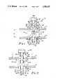
- a second locking elementAttached to the other side of the spacer is a second locking element, which is adapted to engage a second structure, as for example a circuit board, and maintain the second structure in a fixed relationship with respect to the first structure.
- FIG. 28is a cross-section taken substantially along section line 28--28 of FIG. 20.
- the fastener 10is shown in the fully locked position wherein the circuit board 12 has been mounted to the chassis 14 with the spacer 20 providing a predetermined distance A between the circuit board 12 and the chassis 14. As indicated previously, there may be a plurality of apertures 16 in the circuit board 12 to permit the affixation of the circuit board 12 to the chassis 14 at numerous locations.
- first lower head 174has a chamfered lower surface 175 which engages the angled inner cam surfaces 138 of the captivating tabs 132.
- first lower head 174will pivot about the hinged portions 134 to rigidly affix the fastener 110 to the chassis 114.
- the fastener 310is shown in the locked position.
- the circuit board 312is placed over the plunger 360 and in contact with the spacer 320.
- the plunger 360may be pushed into the channel 322 of the fastener body 319 to affix the circuit board 312 to the chassis 314.
- FIG. 35the fastener 410 is shown in the unlocked configuration.
- the tabs 432 of the first locking element 430are biased inwardly and, thus, the angled ribs 438 do not contact the lower surface of the chassis 414.
Landscapes
- Engineering & Computer Science (AREA)
- General Engineering & Computer Science (AREA)
- Mechanical Engineering (AREA)
- Microelectronics & Electronic Packaging (AREA)
- Mounting Of Printed Circuit Boards And The Like (AREA)
Abstract
Description
Claims (2)
Priority Applications (1)
| Application Number | Priority Date | Filing Date | Title |
|---|---|---|---|
| US07/150,441US4786225A (en) | 1981-12-14 | 1988-02-05 | Stand-off fastener |
Applications Claiming Priority (2)
| Application Number | Priority Date | Filing Date | Title |
|---|---|---|---|
| US06/330,260US4502193A (en) | 1981-12-14 | 1981-12-14 | Stand-off fastener |
| US07/150,441US4786225A (en) | 1981-12-14 | 1988-02-05 | Stand-off fastener |
Related Parent Applications (1)
| Application Number | Title | Priority Date | Filing Date |
|---|---|---|---|
| US07013016Continuation | 1987-02-10 |
Publications (1)
| Publication Number | Publication Date |
|---|---|
| US4786225Atrue US4786225A (en) | 1988-11-22 |
Family
ID=26847661
Family Applications (1)
| Application Number | Title | Priority Date | Filing Date |
|---|---|---|---|
| US07/150,441Expired - LifetimeUS4786225A (en) | 1981-12-14 | 1988-02-05 | Stand-off fastener |
Country Status (1)
| Country | Link |
|---|---|
| US (1) | US4786225A (en) |
Cited By (42)
| Publication number | Priority date | Publication date | Assignee | Title |
|---|---|---|---|---|
| US4843976A (en)* | 1988-08-09 | 1989-07-04 | Pigott Maurice J | Plastic pallet |
| US5007779A (en)* | 1989-10-10 | 1991-04-16 | Ford Motor Company | Standoff retainer |
| WO1991012436A1 (en)* | 1990-02-13 | 1991-08-22 | Eustathios Vassiliou | Expansion fastening system with quick lock and release |
| US5100273A (en)* | 1990-09-06 | 1992-03-31 | Eustathios Vassiliou | Expansion fastening system with quick lock and release |
| US5106249A (en)* | 1991-01-07 | 1992-04-21 | Ford Motor Company | Method and apparatus for joining plastic panels to aluminum space frames |
| US5178501A (en)* | 1991-10-29 | 1993-01-12 | Carstairs Arturo R | Axially adjustable screw anchor |
| US5407160A (en)* | 1993-03-12 | 1995-04-18 | Hollingsworth; Don A. | Fastener for holding objects to a perforated wall |
| US5419606A (en)* | 1993-12-27 | 1995-05-30 | Ford Motor Company | Trim panel attaching pin with water seal |
| US5531535A (en)* | 1993-08-14 | 1996-07-02 | Fischerwerke, Artur Fischer Gmbh & Co. Kg | Double connector for connecting two bodies |
| US5562375A (en)* | 1994-11-09 | 1996-10-08 | The United States Of America As Represented By The Administrator Of The National Aeronautics And Space Administration | Push type fastener |
| US5579686A (en)* | 1988-08-09 | 1996-12-03 | Nucon Corporation | Plastic pallet assembly |
| US5632581A (en)* | 1994-06-20 | 1997-05-27 | Illinois Tool Works Inc. | Clip |
| US5754412A (en)* | 1995-10-04 | 1998-05-19 | Hartwell Corporation | Circuit board standoff connector |
| US5807012A (en)* | 1995-07-31 | 1998-09-15 | Motorola, Inc. | Coupling apparatus |
| US5881982A (en)* | 1993-03-12 | 1999-03-16 | Hollingsworth; Don A. | Fastener for holding objects to a perforated wall |
| EP0961374A1 (en)* | 1998-03-27 | 1999-12-01 | Bertoldo & C. Srl | A box for electric material having a removable cover and cover fixing means |
| US6369333B1 (en)* | 1998-02-13 | 2002-04-09 | Intel Corporation | Flexible connection system |
| US6377445B1 (en)* | 2000-08-14 | 2002-04-23 | Gateway, Inc. | Motherboard mounting assembly |
| US20030131465A1 (en)* | 2002-01-16 | 2003-07-17 | Yoon Woong K. | Universal snap-fit spacer |
| US20030223840A1 (en)* | 2000-06-22 | 2003-12-04 | Craig Mengel | Panel fastener |
| US6694566B1 (en)* | 1992-06-22 | 2004-02-24 | Douglas A. J. Mockett | Grommet |
| US6726505B2 (en)* | 2000-07-20 | 2004-04-27 | Silicon Graphics, Inc. | Memory daughter card apparatus, configurations, and methods |
| US20050076602A1 (en)* | 2003-09-17 | 2005-04-14 | Raymond Routhier | Asymmetric drive pin |
| US20050117313A1 (en)* | 2003-11-28 | 2005-06-02 | Speed Tech Corp. | Electric card fixture |
| US20070172327A1 (en)* | 2006-01-24 | 2007-07-26 | Hansen Wayne M | Fastener assembly |
| US20070234531A1 (en)* | 2006-04-10 | 2007-10-11 | Maresh Mark E | Tamper evident feature for package fastening clips |
| US20070289107A1 (en)* | 2006-05-19 | 2007-12-20 | Gm Global Technology Operations, Inc. | Fastener for components of a motor vehicle |
| USD560114S1 (en) | 1992-06-22 | 2008-01-22 | Mockett Douglas A J | Grommet cap |
| US20080056428A1 (en)* | 2006-08-31 | 2008-03-06 | Areva Np Gmbh | Fuel Element for a Light Water Reactor, And Method for Repairing the Fuel Element |
| US20080265115A1 (en)* | 2006-04-10 | 2008-10-30 | International Business Machines Corporation | Tamper Evident Feature for Package Fastening Clips |
| US20090144951A1 (en)* | 2007-12-09 | 2009-06-11 | International Business Machines Corporation | Package Fastening Clip with Tamper Evident Feature |
| US20100018128A1 (en)* | 2006-11-10 | 2010-01-28 | Mea Bausysteme Gmbh | Gutter |
| US20100091440A1 (en)* | 2008-10-09 | 2010-04-15 | International Business Machines Corporation | Implementing Locational Fit Hex Torque Pattern with Low Stress Micro Planes |
| US20100178130A1 (en)* | 2007-07-04 | 2010-07-15 | Zimmer Guenther | Anchor installation in a lightweight construction panel |
| US20100191161A1 (en)* | 2006-10-25 | 2010-07-29 | Corey Philip Mouatt | Exercise apparatus |
| US20110020092A1 (en)* | 2009-07-24 | 2011-01-27 | Pem Management, Inc. | Quick acting panel fastener |
| CN102208787A (en)* | 2011-04-28 | 2011-10-05 | 佛山市海默工业技术有限公司 | Fastening connection mechanism for connection of box cover and box body of distribution box |
| US20110317375A1 (en)* | 2010-06-24 | 2011-12-29 | Tyco Electronics Corporation | Alignment pin for retaining a module on a circuit board |
| US20160138629A1 (en)* | 2013-06-20 | 2016-05-19 | Illinois Tool Works Inc. | Push-in fastener |
| US20190069423A1 (en)* | 2017-08-25 | 2019-02-28 | Hewlett Packard Enterprise Development Lp | Integrated stand-offs for printed circuit boards |
| US10790602B2 (en)* | 2018-10-22 | 2020-09-29 | Weidmüller Interface GmbH & Co. KG | Electrical connector for connecting electrical conductors to a printed circuit board |
| US10960931B2 (en)* | 2018-12-21 | 2021-03-30 | Denso International America, Inc. | Attachment and connecting structure for vehicle component |
Citations (21)
| Publication number | Priority date | Publication date | Assignee | Title |
|---|---|---|---|---|
| US2767877A (en)* | 1954-01-11 | 1956-10-23 | North American Aviation Inc | Rivet adapted to secure two sheets in spaced relationship |
| US3099931A (en)* | 1955-08-26 | 1963-08-06 | Hirsh Mfg Company Sa | Shelf fastener assembly |
| GB1012703A (en)* | 1961-09-05 | 1965-12-08 | Gobin Daude Sa | Fastener device for assembly in an aperture in a support |
| GB1122512A (en)* | 1966-03-07 | 1968-08-07 | Ft Products Ltd | An improved plastics rivet |
| US3406431A (en)* | 1967-05-25 | 1968-10-22 | Coleman Engineering Company In | Releasable fastener for camera cover |
| GB1141913A (en)* | 1965-05-07 | 1969-02-05 | Roger Faillettaz | Wall plug |
| US3568263A (en)* | 1969-10-07 | 1971-03-09 | Illinois Tool Works | Fastener |
| US3697104A (en)* | 1970-02-16 | 1972-10-10 | Rech Activities Petrolieres El | Couplings for tools and safety devices used in oil-wells |
| US3764729A (en)* | 1971-11-29 | 1973-10-09 | Admiral Corp | Releasable lock support for printed circuit module |
| US3811154A (en)* | 1973-02-26 | 1974-05-21 | R Lindeman | Panel mounting fastener |
| US3852849A (en)* | 1973-12-26 | 1974-12-10 | Illinois Tool Works | Panel mounting fastener |
| US3874264A (en)* | 1973-02-16 | 1975-04-01 | Constantine D Polos | Anchor bolt assembly |
| US3918130A (en)* | 1974-01-25 | 1975-11-11 | Hartwell Corp | Initially one piece removable fastener |
| US4007516A (en)* | 1975-05-19 | 1977-02-15 | Richco Plastic Company | Quarter turn locking fastener device |
| US4114509A (en)* | 1977-06-22 | 1978-09-19 | Hartwell Corporation | Fastener plunger entry resistance means |
| US4276806A (en)* | 1978-07-13 | 1981-07-07 | Itw De France | Self-retained and reusable fastener |
| US4403377A (en)* | 1979-12-18 | 1983-09-13 | Nifco Inc. | Fastening device |
| US4426181A (en)* | 1980-11-27 | 1984-01-17 | Nifco Inc. | Binder for panels |
| US4502193A (en)* | 1981-12-14 | 1985-03-05 | Hartwell Corporation | Stand-off fastener |
| US4506419A (en)* | 1982-08-20 | 1985-03-26 | Nifco Inc. | Part-fixing clip |
| US4674930A (en)* | 1981-12-14 | 1987-06-23 | Hartwell Corporation | Stand-off fastener |
- 1988
- 1988-02-05USUS07/150,441patent/US4786225A/ennot_activeExpired - Lifetime
Patent Citations (21)
| Publication number | Priority date | Publication date | Assignee | Title |
|---|---|---|---|---|
| US2767877A (en)* | 1954-01-11 | 1956-10-23 | North American Aviation Inc | Rivet adapted to secure two sheets in spaced relationship |
| US3099931A (en)* | 1955-08-26 | 1963-08-06 | Hirsh Mfg Company Sa | Shelf fastener assembly |
| GB1012703A (en)* | 1961-09-05 | 1965-12-08 | Gobin Daude Sa | Fastener device for assembly in an aperture in a support |
| GB1141913A (en)* | 1965-05-07 | 1969-02-05 | Roger Faillettaz | Wall plug |
| GB1122512A (en)* | 1966-03-07 | 1968-08-07 | Ft Products Ltd | An improved plastics rivet |
| US3406431A (en)* | 1967-05-25 | 1968-10-22 | Coleman Engineering Company In | Releasable fastener for camera cover |
| US3568263A (en)* | 1969-10-07 | 1971-03-09 | Illinois Tool Works | Fastener |
| US3697104A (en)* | 1970-02-16 | 1972-10-10 | Rech Activities Petrolieres El | Couplings for tools and safety devices used in oil-wells |
| US3764729A (en)* | 1971-11-29 | 1973-10-09 | Admiral Corp | Releasable lock support for printed circuit module |
| US3874264A (en)* | 1973-02-16 | 1975-04-01 | Constantine D Polos | Anchor bolt assembly |
| US3811154A (en)* | 1973-02-26 | 1974-05-21 | R Lindeman | Panel mounting fastener |
| US3852849A (en)* | 1973-12-26 | 1974-12-10 | Illinois Tool Works | Panel mounting fastener |
| US3918130A (en)* | 1974-01-25 | 1975-11-11 | Hartwell Corp | Initially one piece removable fastener |
| US4007516A (en)* | 1975-05-19 | 1977-02-15 | Richco Plastic Company | Quarter turn locking fastener device |
| US4114509A (en)* | 1977-06-22 | 1978-09-19 | Hartwell Corporation | Fastener plunger entry resistance means |
| US4276806A (en)* | 1978-07-13 | 1981-07-07 | Itw De France | Self-retained and reusable fastener |
| US4403377A (en)* | 1979-12-18 | 1983-09-13 | Nifco Inc. | Fastening device |
| US4426181A (en)* | 1980-11-27 | 1984-01-17 | Nifco Inc. | Binder for panels |
| US4502193A (en)* | 1981-12-14 | 1985-03-05 | Hartwell Corporation | Stand-off fastener |
| US4674930A (en)* | 1981-12-14 | 1987-06-23 | Hartwell Corporation | Stand-off fastener |
| US4506419A (en)* | 1982-08-20 | 1985-03-26 | Nifco Inc. | Part-fixing clip |
Cited By (71)
| Publication number | Priority date | Publication date | Assignee | Title |
|---|---|---|---|---|
| US4843976A (en)* | 1988-08-09 | 1989-07-04 | Pigott Maurice J | Plastic pallet |
| US5579686A (en)* | 1988-08-09 | 1996-12-03 | Nucon Corporation | Plastic pallet assembly |
| US5007779A (en)* | 1989-10-10 | 1991-04-16 | Ford Motor Company | Standoff retainer |
| WO1991012436A1 (en)* | 1990-02-13 | 1991-08-22 | Eustathios Vassiliou | Expansion fastening system with quick lock and release |
| US5100273A (en)* | 1990-09-06 | 1992-03-31 | Eustathios Vassiliou | Expansion fastening system with quick lock and release |
| US5106249A (en)* | 1991-01-07 | 1992-04-21 | Ford Motor Company | Method and apparatus for joining plastic panels to aluminum space frames |
| US5178501A (en)* | 1991-10-29 | 1993-01-12 | Carstairs Arturo R | Axially adjustable screw anchor |
| US7155775B2 (en) | 1992-06-22 | 2007-01-02 | Mockett Douglas A J | Wire management grommet with non-captive closure member |
| US20050084226A1 (en)* | 1992-06-22 | 2005-04-21 | Mockett Douglas A.J. | Wire management grommet with non-captive closure member |
| US20060123591A1 (en)* | 1992-06-22 | 2006-06-15 | Mockett Douglas A | Wire management grommet with non-captive closure member and sleeve |
| US7124468B2 (en) | 1992-06-22 | 2006-10-24 | Mockett Douglas A J | Wire management grommet with non-captive closure member and sleeve |
| US20080178421A1 (en)* | 1992-06-22 | 2008-07-31 | Mockett Douglas A J | Wire management grommet with non-captive closure member |
| US20050081328A1 (en)* | 1992-06-22 | 2005-04-21 | Mockett Douglas A. | Wire management grommet with non-captive closure member and sleeve |
| US20060196005A1 (en)* | 1992-06-22 | 2006-09-07 | Mockett Douglas A | Wire management grommet with non-captive closure member |
| US20070077796A1 (en)* | 1992-06-22 | 2007-04-05 | Mockett Douglas A | Wire management grommet with non-captive closure member |
| US6694566B1 (en)* | 1992-06-22 | 2004-02-24 | Douglas A. J. Mockett | Grommet |
| US7788766B2 (en) | 1992-06-22 | 2010-09-07 | Mockett Douglas A J | Wire management grommet with non-captive closure member |
| US7383610B2 (en) | 1992-06-22 | 2008-06-10 | Mockett Douglas A J | Wire management grommet with non-captive closure member |
| USD560114S1 (en) | 1992-06-22 | 2008-01-22 | Mockett Douglas A J | Grommet cap |
| US5881982A (en)* | 1993-03-12 | 1999-03-16 | Hollingsworth; Don A. | Fastener for holding objects to a perforated wall |
| US5407160A (en)* | 1993-03-12 | 1995-04-18 | Hollingsworth; Don A. | Fastener for holding objects to a perforated wall |
| US5531535A (en)* | 1993-08-14 | 1996-07-02 | Fischerwerke, Artur Fischer Gmbh & Co. Kg | Double connector for connecting two bodies |
| US5419606A (en)* | 1993-12-27 | 1995-05-30 | Ford Motor Company | Trim panel attaching pin with water seal |
| US5632581A (en)* | 1994-06-20 | 1997-05-27 | Illinois Tool Works Inc. | Clip |
| US5562375A (en)* | 1994-11-09 | 1996-10-08 | The United States Of America As Represented By The Administrator Of The National Aeronautics And Space Administration | Push type fastener |
| US5807012A (en)* | 1995-07-31 | 1998-09-15 | Motorola, Inc. | Coupling apparatus |
| US5754412A (en)* | 1995-10-04 | 1998-05-19 | Hartwell Corporation | Circuit board standoff connector |
| US6369333B1 (en)* | 1998-02-13 | 2002-04-09 | Intel Corporation | Flexible connection system |
| EP0961374A1 (en)* | 1998-03-27 | 1999-12-01 | Bertoldo & C. Srl | A box for electric material having a removable cover and cover fixing means |
| US7207757B2 (en)* | 2000-06-22 | 2007-04-24 | Craig Mengel | Panel fastener |
| US20030223840A1 (en)* | 2000-06-22 | 2003-12-04 | Craig Mengel | Panel fastener |
| US6726505B2 (en)* | 2000-07-20 | 2004-04-27 | Silicon Graphics, Inc. | Memory daughter card apparatus, configurations, and methods |
| US6377445B1 (en)* | 2000-08-14 | 2002-04-23 | Gateway, Inc. | Motherboard mounting assembly |
| US6901646B2 (en)* | 2002-01-16 | 2005-06-07 | Avaya Technology Corp. | Universal snap-fit spacer |
| US20030131465A1 (en)* | 2002-01-16 | 2003-07-17 | Yoon Woong K. | Universal snap-fit spacer |
| US20050076602A1 (en)* | 2003-09-17 | 2005-04-14 | Raymond Routhier | Asymmetric drive pin |
| US7360746B2 (en)* | 2003-09-17 | 2008-04-22 | Raymond Routhier | Asymmetric drive pin |
| US20050117313A1 (en)* | 2003-11-28 | 2005-06-02 | Speed Tech Corp. | Electric card fixture |
| US20070172327A1 (en)* | 2006-01-24 | 2007-07-26 | Hansen Wayne M | Fastener assembly |
| US7484919B2 (en)* | 2006-01-24 | 2009-02-03 | Illinois Tool Works Inc. | Fastener assembly |
| US20070234531A1 (en)* | 2006-04-10 | 2007-10-11 | Maresh Mark E | Tamper evident feature for package fastening clips |
| US7480968B2 (en)* | 2006-04-10 | 2009-01-27 | International Business Machines Corporation | Tamper evident feature for package fastening clips |
| US20080265115A1 (en)* | 2006-04-10 | 2008-10-30 | International Business Machines Corporation | Tamper Evident Feature for Package Fastening Clips |
| CN100581406C (en)* | 2006-04-10 | 2010-01-20 | 国际商业机器公司 | Device for package fastening clips |
| US7870653B2 (en)* | 2006-04-10 | 2011-01-18 | International Business Machines Corporation | Tamper evident feature for package fastening clips |
| US7908717B2 (en)* | 2006-05-19 | 2011-03-22 | GM Global Technology Operations LLC | Fastener for components of a motor vehicle |
| US20070289107A1 (en)* | 2006-05-19 | 2007-12-20 | Gm Global Technology Operations, Inc. | Fastener for components of a motor vehicle |
| US20080056428A1 (en)* | 2006-08-31 | 2008-03-06 | Areva Np Gmbh | Fuel Element for a Light Water Reactor, And Method for Repairing the Fuel Element |
| US8571168B2 (en)* | 2006-08-31 | 2013-10-29 | Areva Gmbh | Fuel element for a light water reactor, and method for repairing the fuel element |
| US8808208B2 (en)* | 2006-10-25 | 2014-08-19 | Corey Philip Mouatt | Exercise apparatus |
| US20100191161A1 (en)* | 2006-10-25 | 2010-07-29 | Corey Philip Mouatt | Exercise apparatus |
| US20100018128A1 (en)* | 2006-11-10 | 2010-01-28 | Mea Bausysteme Gmbh | Gutter |
| US8857132B2 (en)* | 2007-07-04 | 2014-10-14 | Günther Zimmer | Anchor installation in a lightweight construction panel |
| US20100178130A1 (en)* | 2007-07-04 | 2010-07-15 | Zimmer Guenther | Anchor installation in a lightweight construction panel |
| US20090144951A1 (en)* | 2007-12-09 | 2009-06-11 | International Business Machines Corporation | Package Fastening Clip with Tamper Evident Feature |
| US7908719B2 (en)* | 2007-12-09 | 2011-03-22 | International Business Machines Corporation | Package fastening clip with tamper evident feature |
| US20100091440A1 (en)* | 2008-10-09 | 2010-04-15 | International Business Machines Corporation | Implementing Locational Fit Hex Torque Pattern with Low Stress Micro Planes |
| US20110020092A1 (en)* | 2009-07-24 | 2011-01-27 | Pem Management, Inc. | Quick acting panel fastener |
| US9086086B2 (en)* | 2009-07-24 | 2015-07-21 | Pem Management, Inc. | Quick acting panel fastener |
| CN102332661A (en)* | 2010-06-24 | 2012-01-25 | 泰科电子公司 | Alignment pins to hold the module on the board |
| US8325493B2 (en)* | 2010-06-24 | 2012-12-04 | Tyco Electronics Corporation | Alignment pin for retaining a module on a circuit board |
| US20110317375A1 (en)* | 2010-06-24 | 2011-12-29 | Tyco Electronics Corporation | Alignment pin for retaining a module on a circuit board |
| CN102332661B (en)* | 2010-06-24 | 2017-03-01 | 泰科电子公司 | For keeping the alignment pin of module on circuit boards |
| CN102208787B (en)* | 2011-04-28 | 2014-07-09 | 广东黑默工业技术有限公司 | Fastening connection mechanism for connection of box cover and box body of distribution box |
| CN102208787A (en)* | 2011-04-28 | 2011-10-05 | 佛山市海默工业技术有限公司 | Fastening connection mechanism for connection of box cover and box body of distribution box |
| US20160138629A1 (en)* | 2013-06-20 | 2016-05-19 | Illinois Tool Works Inc. | Push-in fastener |
| US9631653B2 (en)* | 2013-06-20 | 2017-04-25 | Illinois Tool Works Inc | Push-in fastener |
| US20190069423A1 (en)* | 2017-08-25 | 2019-02-28 | Hewlett Packard Enterprise Development Lp | Integrated stand-offs for printed circuit boards |
| US10959343B2 (en)* | 2017-08-25 | 2021-03-23 | Hewlett Packard Enterprise Development Lp | Integrated stand-offs for printed circuit boards |
| US10790602B2 (en)* | 2018-10-22 | 2020-09-29 | Weidmüller Interface GmbH & Co. KG | Electrical connector for connecting electrical conductors to a printed circuit board |
| US10960931B2 (en)* | 2018-12-21 | 2021-03-30 | Denso International America, Inc. | Attachment and connecting structure for vehicle component |
Similar Documents
| Publication | Publication Date | Title |
|---|---|---|
| US4786225A (en) | Stand-off fastener | |
| US4674930A (en) | Stand-off fastener | |
| US4502193A (en) | Stand-off fastener | |
| DE4412397C2 (en) | Fully retractable, captive screw | |
| US5754412A (en) | Circuit board standoff connector | |
| US2429833A (en) | Fastening means | |
| US4704059A (en) | Screw grommet | |
| US5897278A (en) | Turn fastener | |
| US4954667A (en) | Electrical box with coupling members | |
| US4970761A (en) | Circuit board isolating fastener | |
| DE3532829A1 (en) | ONE-PIECE LAMP SOCKET | |
| US11542977B2 (en) | Self-locking pin | |
| US2974703A (en) | Plastic anchor member having a transverse screw receiving bore | |
| WO1988010374A1 (en) | Method and apparatus for mounting components on a printed circuit board or similar mounting surface | |
| US4845317A (en) | Threaded insulator | |
| CA2324698C (en) | Screw installed grommet | |
| US5779413A (en) | Fastener system having improved locking element | |
| US20030039529A1 (en) | Blind hole panel nut | |
| US6299468B1 (en) | Retention mechanism for edge card | |
| CA1045419A (en) | Rod retainer | |
| US2433607A (en) | Method of installing fastening means | |
| US4141108A (en) | Cabinet fitting | |
| EP0863315A2 (en) | Fastening device | |
| US5599150A (en) | Clevis pin retainer clips | |
| US3169565A (en) | Self locking screw |
Legal Events
| Date | Code | Title | Description |
|---|---|---|---|
| STCF | Information on status: patent grant | Free format text:PATENTED CASE | |
| FEPP | Fee payment procedure | Free format text:PAYOR NUMBER ASSIGNED (ORIGINAL EVENT CODE: ASPN); ENTITY STATUS OF PATENT OWNER: SMALL ENTITY | |
| FEPP | Fee payment procedure | Free format text:PAT HOLDER CLAIMS SMALL ENTITY STATUS - SMALL BUSINESS (ORIGINAL EVENT CODE: SM02); ENTITY STATUS OF PATENT OWNER: SMALL ENTITY | |
| FPAY | Fee payment | Year of fee payment:4 | |
| FPAY | Fee payment | Year of fee payment:8 | |
| AS | Assignment | Owner name:MEES PIERSON N.V., NEW YORK AGENCY, NEW YORK Free format text:ASSIGNMENT OF SECURITY INTEREST IN UNITED STATES TRADEMARKS AND PATENTS;ASSIGNOR:HARTWELL CORPORATION;REEL/FRAME:008430/0578 Effective date:19970324 | |
| AS | Assignment | Owner name:MEESPIERSON CAPITAL CORP., DELAWARE CORPORATION, N Free format text:ASSIGNMENT OF SECURITY INTEREST IN UNITED STATES TRADEMARKS AND PATENTS;ASSIGNOR:MEES PIERSON, N.V., NEW YORK AGENCY;REEL/FRAME:008744/0973 Effective date:19971120 | |
| FPAY | Fee payment | Year of fee payment:12 | |
| AS | Assignment | Owner name:HARTWELL CORPORATION, CALIFORNIA Free format text:RELEASE OF ASSIGNMENT OF SECURITY INTEREST;ASSIGNOR:FORTIS CAPITOL CORP.;REEL/FRAME:016290/0601 Effective date:20050711 | |
| AS | Assignment | Owner name:THE BANK OF NEW YORK MELLON TRUST COMPANY, N.A.,, Free format text:SECURITY INTEREST;ASSIGNORS:TRANSDIGM, INC.;ADAMS RITE AEROSPACE, INC.;AEROCONTROLEX GROUP, INC.;AND OTHERS;REEL/FRAME:048365/0499 Effective date:20190214 | |
| AS | Assignment | Owner name:THE BANK OF NEW YORK MELLON TRUST COMPANY, N.A., AS TRUSTEE AND NOTES COLLATERAL AGENT, ILLINOIS Free format text:PATENT SECURITY AGREEMENT;ASSIGNORS:AIRBORNE SYSTEMS NORTH AMERICA OF NJ INC.;ACME AEROSPACE, INC.;ADAMS RITE AEROSPACE, INC.;AND OTHERS;REEL/FRAME:052352/0704 Effective date:20200408 | |
| AS | Assignment | Owner name:APICAL INDUSTRIES, INC., OHIO Free format text:RELEASE BY SECURED PARTY;ASSIGNOR:THE BANK OF NEW YORK MELLON TRUST COMPANY, N.A., AS TRUSTEE;REEL/FRAME:063363/0753 Effective date:20230410 Owner name:SIMPLEX MANUFACTURING CO., OHIO Free format text:RELEASE BY SECURED PARTY;ASSIGNOR:THE BANK OF NEW YORK MELLON TRUST COMPANY, N.A., AS TRUSTEE;REEL/FRAME:063363/0753 Effective date:20230410 Owner name:CHELTON, INC. (N/K/A CHELTON AVIONICS, INC.), ARIZONA Free format text:RELEASE BY SECURED PARTY;ASSIGNOR:THE BANK OF NEW YORK MELLON TRUST COMPANY, N.A., AS TRUSTEE;REEL/FRAME:063363/0753 Effective date:20230410 Owner name:PALOMAR PRODUCTS, INC., CALIFORNIA Free format text:RELEASE BY SECURED PARTY;ASSIGNOR:THE BANK OF NEW YORK MELLON TRUST COMPANY, N.A., AS TRUSTEE;REEL/FRAME:063363/0753 Effective date:20230410 Owner name:KORRY ELECTRONICS CO., WASHINGTON Free format text:RELEASE BY SECURED PARTY;ASSIGNOR:THE BANK OF NEW YORK MELLON TRUST COMPANY, N.A., AS TRUSTEE;REEL/FRAME:063363/0753 Effective date:20230410 Owner name:MASON ELECTRIC CO., CALIFORNIA Free format text:RELEASE BY SECURED PARTY;ASSIGNOR:THE BANK OF NEW YORK MELLON TRUST COMPANY, N.A., AS TRUSTEE;REEL/FRAME:063363/0753 Effective date:20230410 Owner name:TA AEROSPACE CO., CALIFORNIA Free format text:RELEASE BY SECURED PARTY;ASSIGNOR:THE BANK OF NEW YORK MELLON TRUST COMPANY, N.A., AS TRUSTEE;REEL/FRAME:063363/0753 Effective date:20230410 Owner name:NMC GROUP INC., CALIFORNIA Free format text:RELEASE BY SECURED PARTY;ASSIGNOR:THE BANK OF NEW YORK MELLON TRUST COMPANY, N.A., AS TRUSTEE;REEL/FRAME:063363/0753 Effective date:20230410 Owner name:LEACH INTERNATIONAL CORPORATION, CALIFORNIA Free format text:RELEASE BY SECURED PARTY;ASSIGNOR:THE BANK OF NEW YORK MELLON TRUST COMPANY, N.A., AS TRUSTEE;REEL/FRAME:063363/0753 Effective date:20230410 Owner name:ARMTEC DEFENSE PRODUCTS COMPANY, CALIFORNIA Free format text:RELEASE BY SECURED PARTY;ASSIGNOR:THE BANK OF NEW YORK MELLON TRUST COMPANY, N.A., AS TRUSTEE;REEL/FRAME:063363/0753 Effective date:20230410 Owner name:ARMTEC COUNTERMEASURES CO., NORTH CAROLINA Free format text:RELEASE BY SECURED PARTY;ASSIGNOR:THE BANK OF NEW YORK MELLON TRUST COMPANY, N.A., AS TRUSTEE;REEL/FRAME:063363/0753 Effective date:20230410 Owner name:YOUNG & FRANKLIN INC., NEW YORK Free format text:RELEASE BY SECURED PARTY;ASSIGNOR:THE BANK OF NEW YORK MELLON TRUST COMPANY, N.A., AS TRUSTEE;REEL/FRAME:063363/0753 Effective date:20230410 Owner name:WHIPPANY ACTUATION SYSTEMS, LLC, NEW JERSEY Free format text:RELEASE BY SECURED PARTY;ASSIGNOR:THE BANK OF NEW YORK MELLON TRUST COMPANY, N.A., AS TRUSTEE;REEL/FRAME:063363/0753 Effective date:20230410 Owner name:WESTERN SKY INDUSTRIES, LLC, KENTUCKY Free format text:RELEASE BY SECURED PARTY;ASSIGNOR:THE BANK OF NEW YORK MELLON TRUST COMPANY, N.A., AS TRUSTEE;REEL/FRAME:063363/0753 Effective date:20230410 Owner name:TRANSCOIL LLC, PENNSYLVANIA Free format text:RELEASE BY SECURED PARTY;ASSIGNOR:THE BANK OF NEW YORK MELLON TRUST COMPANY, N.A., AS TRUSTEE;REEL/FRAME:063363/0753 Effective date:20230410 Owner name:TELAIR INTERNATIONAL LLC, NEW YORK Free format text:RELEASE BY SECURED PARTY;ASSIGNOR:THE BANK OF NEW YORK MELLON TRUST COMPANY, N.A., AS TRUSTEE;REEL/FRAME:063363/0753 Effective date:20230410 Owner name:TEAC AEROSPACE TECHNOLOGIES, INC., FLORIDA Free format text:RELEASE BY SECURED PARTY;ASSIGNOR:THE BANK OF NEW YORK MELLON TRUST COMPANY, N.A., AS TRUSTEE;REEL/FRAME:063363/0753 Effective date:20230410 Owner name:TACTAIR FLUID CONTROLS INC., NEW YORK Free format text:RELEASE BY SECURED PARTY;ASSIGNOR:THE BANK OF NEW YORK MELLON TRUST COMPANY, N.A., AS TRUSTEE;REEL/FRAME:063363/0753 Effective date:20230410 Owner name:SHIELD RESTRAINT SYSTEMS, INC., INDIANA Free format text:RELEASE BY SECURED PARTY;ASSIGNOR:THE BANK OF NEW YORK MELLON TRUST COMPANY, N.A., AS TRUSTEE;REEL/FRAME:063363/0753 Effective date:20230410 Owner name:SEMCO INSTRUMENTS, INC., CONNECTICUT Free format text:RELEASE BY SECURED PARTY;ASSIGNOR:THE BANK OF NEW YORK MELLON TRUST COMPANY, N.A., AS TRUSTEE;REEL/FRAME:063363/0753 Effective date:20230410 Owner name:SCHNELLER LLC, OHIO Free format text:RELEASE BY SECURED PARTY;ASSIGNOR:THE BANK OF NEW YORK MELLON TRUST COMPANY, N.A., AS TRUSTEE;REEL/FRAME:063363/0753 Effective date:20230410 Owner name:PNEUDRAULICS, INC., CALIFORNIA Free format text:RELEASE BY SECURED PARTY;ASSIGNOR:THE BANK OF NEW YORK MELLON TRUST COMPANY, N.A., AS TRUSTEE;REEL/FRAME:063363/0753 Effective date:20230410 Owner name:PEXCO AEROSPACE, INC., WASHINGTON Free format text:RELEASE BY SECURED PARTY;ASSIGNOR:THE BANK OF NEW YORK MELLON TRUST COMPANY, N.A., AS TRUSTEE;REEL/FRAME:063363/0753 Effective date:20230410 Owner name:MARATHONNORCO AEROSPACE, INC., TEXAS Free format text:RELEASE BY SECURED PARTY;ASSIGNOR:THE BANK OF NEW YORK MELLON TRUST COMPANY, N.A., AS TRUSTEE;REEL/FRAME:063363/0753 Effective date:20230410 Owner name:HARTWELL CORPORATION, CALIFORNIA Free format text:RELEASE BY SECURED PARTY;ASSIGNOR:THE BANK OF NEW YORK MELLON TRUST COMPANY, N.A., AS TRUSTEE;REEL/FRAME:063363/0753 Effective date:20230410 Owner name:HARCO LLC, CONNECTICUT Free format text:RELEASE BY SECURED PARTY;ASSIGNOR:THE BANK OF NEW YORK MELLON TRUST COMPANY, N.A., AS TRUSTEE;REEL/FRAME:063363/0753 Effective date:20230410 Owner name:HARCO LABORATORIES, INC., CONNECTICUT Free format text:RELEASE BY SECURED PARTY;ASSIGNOR:THE BANK OF NEW YORK MELLON TRUST COMPANY, N.A., AS TRUSTEE;REEL/FRAME:063363/0753 Effective date:20230410 Owner name:ELECTROMECH TECHNOLOGIES LLC, KANSAS Free format text:RELEASE BY SECURED PARTY;ASSIGNOR:THE BANK OF NEW YORK MELLON TRUST COMPANY, N.A., AS TRUSTEE;REEL/FRAME:063363/0753 Effective date:20230410 Owner name:DUKES AEROSPACE, INC., OHIO Free format text:RELEASE BY SECURED PARTY;ASSIGNOR:THE BANK OF NEW YORK MELLON TRUST COMPANY, N.A., AS TRUSTEE;REEL/FRAME:063363/0753 Effective date:20230410 Owner name:DATA DEVICE CORPORATION, NEW YORK Free format text:RELEASE BY SECURED PARTY;ASSIGNOR:THE BANK OF NEW YORK MELLON TRUST COMPANY, N.A., AS TRUSTEE;REEL/FRAME:063363/0753 Effective date:20230410 Owner name:CHAMPION AEROSPACE LLC, SOUTH CAROLINA Free format text:RELEASE BY SECURED PARTY;ASSIGNOR:THE BANK OF NEW YORK MELLON TRUST COMPANY, N.A., AS TRUSTEE;REEL/FRAME:063363/0753 Effective date:20230410 Owner name:CEF INDUSTRIES, INC., ILLINOIS Free format text:RELEASE BY SECURED PARTY;ASSIGNOR:THE BANK OF NEW YORK MELLON TRUST COMPANY, N.A., AS TRUSTEE;REEL/FRAME:063363/0753 Effective date:20230410 Owner name:BRUCE AEROSPACE, INC., NEVADA Free format text:RELEASE BY SECURED PARTY;ASSIGNOR:THE BANK OF NEW YORK MELLON TRUST COMPANY, N.A., AS TRUSTEE;REEL/FRAME:063363/0753 Effective date:20230410 Owner name:BREEZE EASTERN CORPORATION, NEW JERSEY Free format text:RELEASE BY SECURED PARTY;ASSIGNOR:THE BANK OF NEW YORK MELLON TRUST COMPANY, N.A., AS TRUSTEE;REEL/FRAME:063363/0753 Effective date:20230410 Owner name:BEAM'S INDUSTRIES, OKLAHOMA Free format text:RELEASE BY SECURED PARTY;ASSIGNOR:THE BANK OF NEW YORK MELLON TRUST COMPANY, N.A., AS TRUSTEE;REEL/FRAME:063363/0753 Effective date:20230410 Owner name:AVTECH TYEE, INC., WASHINGTON Free format text:RELEASE BY SECURED PARTY;ASSIGNOR:THE BANK OF NEW YORK MELLON TRUST COMPANY, N.A., AS TRUSTEE;REEL/FRAME:063363/0753 Effective date:20230410 Owner name:AVIONICS SPECIALTIES, INC., OHIO Free format text:RELEASE BY SECURED PARTY;ASSIGNOR:THE BANK OF NEW YORK MELLON TRUST COMPANY, N.A., AS TRUSTEE;REEL/FRAME:063363/0753 Effective date:20230410 Owner name:AVIONIC INSTRUMENTS LLC, NEW JERSEY Free format text:RELEASE BY SECURED PARTY;ASSIGNOR:THE BANK OF NEW YORK MELLON TRUST COMPANY, N.A., AS TRUSTEE;REEL/FRAME:063363/0753 Effective date:20230410 Owner name:ARKWIN INDUSTRIES, INC., NEW YORK Free format text:RELEASE BY SECURED PARTY;ASSIGNOR:THE BANK OF NEW YORK MELLON TRUST COMPANY, N.A., AS TRUSTEE;REEL/FRAME:063363/0753 Effective date:20230410 Owner name:AMSAFE, INC., ARIZONA Free format text:RELEASE BY SECURED PARTY;ASSIGNOR:THE BANK OF NEW YORK MELLON TRUST COMPANY, N.A., AS TRUSTEE;REEL/FRAME:063363/0753 Effective date:20230410 Owner name:AMSAFE COMMERCIAL PRODUCTS INC., INDIANA Free format text:RELEASE BY SECURED PARTY;ASSIGNOR:THE BANK OF NEW YORK MELLON TRUST COMPANY, N.A., AS TRUSTEE;REEL/FRAME:063363/0753 Effective date:20230410 Owner name:AIRBORNE SYSTEMS NORTH AMERICA OF NJ INC., NEW JERSEY Free format text:RELEASE BY SECURED PARTY;ASSIGNOR:THE BANK OF NEW YORK MELLON TRUST COMPANY, N.A., AS TRUSTEE;REEL/FRAME:063363/0753 Effective date:20230410 Owner name:AIRBORNE HOLDINGS, INC., OHIO Free format text:RELEASE BY SECURED PARTY;ASSIGNOR:THE BANK OF NEW YORK MELLON TRUST COMPANY, N.A., AS TRUSTEE;REEL/FRAME:063363/0753 Effective date:20230410 Owner name:AEROSONIC CORPORATION, FLORIDA Free format text:RELEASE BY SECURED PARTY;ASSIGNOR:THE BANK OF NEW YORK MELLON TRUST COMPANY, N.A., AS TRUSTEE;REEL/FRAME:063363/0753 Effective date:20230410 Owner name:AEROCONTROLEX GROUP, INC., OHIO Free format text:RELEASE BY SECURED PARTY;ASSIGNOR:THE BANK OF NEW YORK MELLON TRUST COMPANY, N.A., AS TRUSTEE;REEL/FRAME:063363/0753 Effective date:20230410 Owner name:ADAMS RITE AEROSPACE, INC., CALIFORNIA Free format text:RELEASE BY SECURED PARTY;ASSIGNOR:THE BANK OF NEW YORK MELLON TRUST COMPANY, N.A., AS TRUSTEE;REEL/FRAME:063363/0753 Effective date:20230410 Owner name:ACME AEROSPACE, INC., ARIZONA Free format text:RELEASE BY SECURED PARTY;ASSIGNOR:THE BANK OF NEW YORK MELLON TRUST COMPANY, N.A., AS TRUSTEE;REEL/FRAME:063363/0753 Effective date:20230410 Owner name:TRANSDIGM GROUP INCORPORATED, OHIO Free format text:RELEASE BY SECURED PARTY;ASSIGNOR:THE BANK OF NEW YORK MELLON TRUST COMPANY, N.A., AS TRUSTEE;REEL/FRAME:063363/0753 Effective date:20230410 Owner name:TRANSDIGM, INC., OHIO Free format text:RELEASE BY SECURED PARTY;ASSIGNOR:THE BANK OF NEW YORK MELLON TRUST COMPANY, N.A., AS TRUSTEE;REEL/FRAME:063363/0753 Effective date:20230410 | |
| AS | Assignment | Owner name:CEF INDUSTRIES, INC., ILLINOIS Free format text:RELEASE OF PATENT SECURITY AGREEMENT RECORDED FEBRUARY 19, 2019 AT REEL/FRAME 048365/0499;ASSIGNOR:THE BANK OF NEW YORK MELLON TRUST COMPANY, N.A., AS TRUSTEE;REEL/FRAME:067640/0147 Effective date:20240514 Owner name:SCHNELLER, INC., OHIO Free format text:RELEASE OF PATENT SECURITY AGREEMENT RECORDED FEBRUARY 19, 2019 AT REEL/FRAME 048365/0499;ASSIGNOR:THE BANK OF NEW YORK MELLON TRUST COMPANY, N.A., AS TRUSTEE;REEL/FRAME:067640/0147 Effective date:20240514 Owner name:ACME AEROSPACE, INC., ARIZONA Free format text:RELEASE OF PATENT SECURITY AGREEMENT RECORDED FEBRUARY 19, 2019 AT REEL/FRAME 048365/0499;ASSIGNOR:THE BANK OF NEW YORK MELLON TRUST COMPANY, N.A., AS TRUSTEE;REEL/FRAME:067640/0147 Effective date:20240514 Owner name:ADAMS RITE AEROSPACE, INC., CALIFORNIA Free format text:RELEASE OF PATENT SECURITY AGREEMENT RECORDED FEBRUARY 19, 2019 AT REEL/FRAME 048365/0499;ASSIGNOR:THE BANK OF NEW YORK MELLON TRUST COMPANY, N.A., AS TRUSTEE;REEL/FRAME:067640/0147 Effective date:20240514 Owner name:CALSPAN SYSTEMS, LLC, VIRGINIA Free format text:RELEASE OF PATENT SECURITY AGREEMENT RECORDED FEBRUARY 19, 2019 AT REEL/FRAME 048365/0499;ASSIGNOR:THE BANK OF NEW YORK MELLON TRUST COMPANY, N.A., AS TRUSTEE;REEL/FRAME:067640/0147 Effective date:20240514 Owner name:CALSPAN AERO SYSTEMS ENGINEERING, INC., MINNESOTA Free format text:RELEASE OF PATENT SECURITY AGREEMENT RECORDED FEBRUARY 19, 2019 AT REEL/FRAME 048365/0499;ASSIGNOR:THE BANK OF NEW YORK MELLON TRUST COMPANY, N.A., AS TRUSTEE;REEL/FRAME:067640/0147 Effective date:20240514 Owner name:TELAIR US LLC, NORTH CAROLINA Free format text:RELEASE OF PATENT SECURITY AGREEMENT RECORDED FEBRUARY 19, 2019 AT REEL/FRAME 048365/0499;ASSIGNOR:THE BANK OF NEW YORK MELLON TRUST COMPANY, N.A., AS TRUSTEE;REEL/FRAME:067640/0147 Effective date:20240514 Owner name:PEXCO AEROSPACE, INC., WASHINGTON Free format text:RELEASE OF PATENT SECURITY AGREEMENT RECORDED FEBRUARY 19, 2019 AT REEL/FRAME 048365/0499;ASSIGNOR:THE BANK OF NEW YORK MELLON TRUST COMPANY, N.A., AS TRUSTEE;REEL/FRAME:067640/0147 Effective date:20240514 Owner name:HARCO, LLC (N/K/A HARCOSEMCO LLC), CONNECTICUT Free format text:RELEASE OF PATENT SECURITY AGREEMENT RECORDED FEBRUARY 19, 2019 AT REEL/FRAME 048365/0499;ASSIGNOR:THE BANK OF NEW YORK MELLON TRUST COMPANY, N.A., AS TRUSTEE;REEL/FRAME:067640/0147 Effective date:20240514 Owner name:HARCOSEMCO LLC, CONNECTICUT Free format text:RELEASE OF PATENT SECURITY AGREEMENT RECORDED FEBRUARY 19, 2019 AT REEL/FRAME 048365/0499;ASSIGNOR:THE BANK OF NEW YORK MELLON TRUST COMPANY, N.A., AS TRUSTEE;REEL/FRAME:067640/0147 Effective date:20240514 Owner name:AIRBORNE SYSTEMS NA, INC., OHIO Free format text:RELEASE OF PATENT SECURITY AGREEMENT RECORDED FEBRUARY 19, 2019 AT REEL/FRAME 048365/0499;ASSIGNOR:THE BANK OF NEW YORK MELLON TRUST COMPANY, N.A., AS TRUSTEE;REEL/FRAME:067640/0147 Effective date:20240514 Owner name:AERO-INSTRUMENTS CO., LLC, OHIO Free format text:RELEASE OF PATENT SECURITY AGREEMENT RECORDED FEBRUARY 19, 2019 AT REEL/FRAME 048365/0499;ASSIGNOR:THE BANK OF NEW YORK MELLON TRUST COMPANY, N.A., AS TRUSTEE;REEL/FRAME:067640/0147 Effective date:20240514 Owner name:APICAL INDUSTRIES, INC., OHIO Free format text:RELEASE OF PATENT SECURITY AGREEMENT RECORDED FEBRUARY 19, 2019 AT REEL/FRAME 048365/0499;ASSIGNOR:THE BANK OF NEW YORK MELLON TRUST COMPANY, N.A., AS TRUSTEE;REEL/FRAME:067640/0147 Effective date:20240514 Owner name:SIMPLEX MANUFACTURING CO., OHIO Free format text:RELEASE OF PATENT SECURITY AGREEMENT RECORDED FEBRUARY 19, 2019 AT REEL/FRAME 048365/0499;ASSIGNOR:THE BANK OF NEW YORK MELLON TRUST COMPANY, N.A., AS TRUSTEE;REEL/FRAME:067640/0147 Effective date:20240514 Owner name:CHELTON, INC. (N/K/A CHELTON AVIONICS, INC.), ARIZONA Free format text:RELEASE OF PATENT SECURITY AGREEMENT RECORDED FEBRUARY 19, 2019 AT REEL/FRAME 048365/0499;ASSIGNOR:THE BANK OF NEW YORK MELLON TRUST COMPANY, N.A., AS TRUSTEE;REEL/FRAME:067640/0147 Effective date:20240514 Owner name:MEMTRON TECHNOLOGIES CO., MICHIGAN Free format text:RELEASE OF PATENT SECURITY AGREEMENT RECORDED FEBRUARY 19, 2019 AT REEL/FRAME 048365/0499;ASSIGNOR:THE BANK OF NEW YORK MELLON TRUST COMPANY, N.A., AS TRUSTEE;REEL/FRAME:067640/0147 Effective date:20240514 Owner name:ROLLS-ROYCE PLC, UNITED KINGDOM Free format text:RELEASE OF PATENT SECURITY AGREEMENT RECORDED FEBRUARY 19, 2019 AT REEL/FRAME 048365/0499;ASSIGNOR:THE BANK OF NEW YORK MELLON TRUST COMPANY, N.A., AS TRUSTEE;REEL/FRAME:067640/0147 Effective date:20240514 Owner name:PALOMAR PRODUCTS, INC., CALIFORNIA Free format text:RELEASE OF PATENT SECURITY AGREEMENT RECORDED FEBRUARY 19, 2019 AT REEL/FRAME 048365/0499;ASSIGNOR:THE BANK OF NEW YORK MELLON TRUST COMPANY, N.A., AS TRUSTEE;REEL/FRAME:067640/0147 Effective date:20240514 Owner name:KORRY ELECTRONICS CO., WASHINGTON Free format text:RELEASE OF PATENT SECURITY AGREEMENT RECORDED FEBRUARY 19, 2019 AT REEL/FRAME 048365/0499;ASSIGNOR:THE BANK OF NEW YORK MELLON TRUST COMPANY, N.A., AS TRUSTEE;REEL/FRAME:067640/0147 Effective date:20240514 Owner name:MASON ELECTRIC CO., CALIFORNIA Free format text:RELEASE OF PATENT SECURITY AGREEMENT RECORDED FEBRUARY 19, 2019 AT REEL/FRAME 048365/0499;ASSIGNOR:THE BANK OF NEW YORK MELLON TRUST COMPANY, N.A., AS TRUSTEE;REEL/FRAME:067640/0147 Effective date:20240514 Owner name:TA AEROSPACE CO., CALIFORNIA Free format text:RELEASE OF PATENT SECURITY AGREEMENT RECORDED FEBRUARY 19, 2019 AT REEL/FRAME 048365/0499;ASSIGNOR:THE BANK OF NEW YORK MELLON TRUST COMPANY, N.A., AS TRUSTEE;REEL/FRAME:067640/0147 Effective date:20240514 Owner name:NMC GROUP, INC., CALIFORNIA Free format text:RELEASE OF PATENT SECURITY AGREEMENT RECORDED FEBRUARY 19, 2019 AT REEL/FRAME 048365/0499;ASSIGNOR:THE BANK OF NEW YORK MELLON TRUST COMPANY, N.A., AS TRUSTEE;REEL/FRAME:067640/0147 Effective date:20240514 Owner name:SOURIAU USA, INC., PENNSYLVANIA Free format text:RELEASE OF PATENT SECURITY AGREEMENT RECORDED FEBRUARY 19, 2019 AT REEL/FRAME 048365/0499;ASSIGNOR:THE BANK OF NEW YORK MELLON TRUST COMPANY, N.A., AS TRUSTEE;REEL/FRAME:067640/0147 Effective date:20240514 Owner name:LEACH INTERNATIONAL CORPORATION, CALIFORNIA Free format text:RELEASE OF PATENT SECURITY AGREEMENT RECORDED FEBRUARY 19, 2019 AT REEL/FRAME 048365/0499;ASSIGNOR:THE BANK OF NEW YORK MELLON TRUST COMPANY, N.A., AS TRUSTEE;REEL/FRAME:067640/0147 Effective date:20240514 Owner name:JOSLYN SUNBANK COMPANY LLC, CALIFORNIA Free format text:RELEASE OF PATENT SECURITY AGREEMENT RECORDED FEBRUARY 19, 2019 AT REEL/FRAME 048365/0499;ASSIGNOR:THE BANK OF NEW YORK MELLON TRUST COMPANY, N.A., AS TRUSTEE;REEL/FRAME:067640/0147 Effective date:20240514 Owner name:ARMTEC DEFENSE PRODUCTS COMPANY, CALIFORNIA Free format text:RELEASE OF PATENT SECURITY AGREEMENT RECORDED FEBRUARY 19, 2019 AT REEL/FRAME 048365/0499;ASSIGNOR:THE BANK OF NEW YORK MELLON TRUST COMPANY, N.A., AS TRUSTEE;REEL/FRAME:067640/0147 Effective date:20240514 Owner name:ADVANCED INPUT DEVICES, INC., IDAHO Free format text:RELEASE OF PATENT SECURITY AGREEMENT RECORDED FEBRUARY 19, 2019 AT REEL/FRAME 048365/0499;ASSIGNOR:THE BANK OF NEW YORK MELLON TRUST COMPANY, N.A., AS TRUSTEE;REEL/FRAME:067640/0147 Effective date:20240514 Owner name:ARMTEC COUNTERMEASURES CO., NORTH CAROLINA Free format text:RELEASE OF PATENT SECURITY AGREEMENT RECORDED FEBRUARY 19, 2019 AT REEL/FRAME 048365/0499;ASSIGNOR:THE BANK OF NEW YORK MELLON TRUST COMPANY, N.A., AS TRUSTEE;REEL/FRAME:067640/0147 Effective date:20240514 Owner name:YOUNG & FRANKLIN INC., NEW YORK Free format text:RELEASE OF PATENT SECURITY AGREEMENT RECORDED FEBRUARY 19, 2019 AT REEL/FRAME 048365/0499;ASSIGNOR:THE BANK OF NEW YORK MELLON TRUST COMPANY, N.A., AS TRUSTEE;REEL/FRAME:067640/0147 Effective date:20240514 Owner name:WHIPPANY ACTUATION SYSTEMS, LLC, NEW JERSEY Free format text:RELEASE OF PATENT SECURITY AGREEMENT RECORDED FEBRUARY 19, 2019 AT REEL/FRAME 048365/0499;ASSIGNOR:THE BANK OF NEW YORK MELLON TRUST COMPANY, N.A., AS TRUSTEE;REEL/FRAME:067640/0147 Effective date:20240514 Owner name:SOUTHCO, INC., PENNSYLVANIA Free format text:RELEASE OF PATENT SECURITY AGREEMENT RECORDED FEBRUARY 19, 2019 AT REEL/FRAME 048365/0499;ASSIGNOR:THE BANK OF NEW YORK MELLON TRUST COMPANY, N.A., AS TRUSTEE;REEL/FRAME:067640/0147 Effective date:20240514 Owner name:TRANSICOIL INC., PENNSYLVANIA Free format text:RELEASE OF PATENT SECURITY AGREEMENT RECORDED FEBRUARY 19, 2019 AT REEL/FRAME 048365/0499;ASSIGNOR:THE BANK OF NEW YORK MELLON TRUST COMPANY, N.A., AS TRUSTEE;REEL/FRAME:067640/0147 Effective date:20240514 Owner name:AEROCONTROLEX GROUP, INC., OHIO Free format text:RELEASE OF PATENT SECURITY AGREEMENT RECORDED FEBRUARY 19, 2019 AT REEL/FRAME 048365/0499;ASSIGNOR:THE BANK OF NEW YORK MELLON TRUST COMPANY, N.A., AS TRUSTEE;REEL/FRAME:067640/0147 Effective date:20240514 Owner name:TURNTIME TECHNOLOGIES AB, SWEDEN Free format text:RELEASE OF PATENT SECURITY AGREEMENT RECORDED FEBRUARY 19, 2019 AT REEL/FRAME 048365/0499;ASSIGNOR:THE BANK OF NEW YORK MELLON TRUST COMPANY, N.A., AS TRUSTEE;REEL/FRAME:067640/0147 Effective date:20240514 Owner name:NORDISK AVIATION PRODUCTS AS, NORWAY Free format text:RELEASE OF PATENT SECURITY AGREEMENT RECORDED FEBRUARY 19, 2019 AT REEL/FRAME 048365/0499;ASSIGNOR:THE BANK OF NEW YORK MELLON TRUST COMPANY, N.A., AS TRUSTEE;REEL/FRAME:067640/0147 Effective date:20240514 Owner name:TELAIR INTERNATIONAL AB, SWEDEN Free format text:RELEASE OF PATENT SECURITY AGREEMENT RECORDED FEBRUARY 19, 2019 AT REEL/FRAME 048365/0499;ASSIGNOR:THE BANK OF NEW YORK MELLON TRUST COMPANY, N.A., AS TRUSTEE;REEL/FRAME:067640/0147 Effective date:20240514 Owner name:TELAIR INTERNATIONAL GMBH, GERMANY Free format text:RELEASE OF PATENT SECURITY AGREEMENT RECORDED FEBRUARY 19, 2019 AT REEL/FRAME 048365/0499;ASSIGNOR:THE BANK OF NEW YORK MELLON TRUST COMPANY, N.A., AS TRUSTEE;REEL/FRAME:067640/0147 Effective date:20240514 Owner name:TEAC AEROSPACE TECHNOLOGIES, INC., FLORIDA Free format text:RELEASE OF PATENT SECURITY AGREEMENT RECORDED FEBRUARY 19, 2019 AT REEL/FRAME 048365/0499;ASSIGNOR:THE BANK OF NEW YORK MELLON TRUST COMPANY, N.A., AS TRUSTEE;REEL/FRAME:067640/0147 Effective date:20240514 Owner name:TACTAIR FLUID CONTROLS, INC., NEW YORK Free format text:RELEASE OF PATENT SECURITY AGREEMENT RECORDED FEBRUARY 19, 2019 AT REEL/FRAME 048365/0499;ASSIGNOR:THE BANK OF NEW YORK MELLON TRUST COMPANY, N.A., AS TRUSTEE;REEL/FRAME:067640/0147 Effective date:20240514 Owner name:SEMCO INSTRUMENTS, INC., CONNECTICUT Free format text:RELEASE OF PATENT SECURITY AGREEMENT RECORDED FEBRUARY 19, 2019 AT REEL/FRAME 048365/0499;ASSIGNOR:THE BANK OF NEW YORK MELLON TRUST COMPANY, N.A., AS TRUSTEE;REEL/FRAME:067640/0147 Effective date:20240514 Owner name:SCHNELLER LLC, OHIO Free format text:RELEASE OF PATENT SECURITY AGREEMENT RECORDED FEBRUARY 19, 2019 AT REEL/FRAME 048365/0499;ASSIGNOR:THE BANK OF NEW YORK MELLON TRUST COMPANY, N.A., AS TRUSTEE;REEL/FRAME:067640/0147 Effective date:20240514 Owner name:PNEUDRAULICS, INC., CALIFORNIA Free format text:RELEASE OF PATENT SECURITY AGREEMENT RECORDED FEBRUARY 19, 2019 AT REEL/FRAME 048365/0499;ASSIGNOR:THE BANK OF NEW YORK MELLON TRUST COMPANY, N.A., AS TRUSTEE;REEL/FRAME:067640/0147 Effective date:20240514 Owner name:MARATHONNORCO AEROSPACE, INC., TEXAS Free format text:RELEASE OF PATENT SECURITY AGREEMENT RECORDED FEBRUARY 19, 2019 AT REEL/FRAME 048365/0499;ASSIGNOR:THE BANK OF NEW YORK MELLON TRUST COMPANY, N.A., AS TRUSTEE;REEL/FRAME:067640/0147 Effective date:20240514 Owner name:HARTWELL CORPORATION, CALIFORNIA Free format text:RELEASE OF PATENT SECURITY AGREEMENT RECORDED FEBRUARY 19, 2019 AT REEL/FRAME 048365/0499;ASSIGNOR:THE BANK OF NEW YORK MELLON TRUST COMPANY, N.A., AS TRUSTEE;REEL/FRAME:067640/0147 Effective date:20240514 Owner name:HARCO CORPORATION, CONNECTICUT Free format text:RELEASE OF PATENT SECURITY AGREEMENT RECORDED FEBRUARY 19, 2019 AT REEL/FRAME 048365/0499;ASSIGNOR:THE BANK OF NEW YORK MELLON TRUST COMPANY, N.A., AS TRUSTEE;REEL/FRAME:067640/0147 Effective date:20240514 Owner name:CORRPRO COMPANIES, INC., MISSOURI Free format text:RELEASE OF PATENT SECURITY AGREEMENT RECORDED FEBRUARY 19, 2019 AT REEL/FRAME 048365/0499;ASSIGNOR:THE BANK OF NEW YORK MELLON TRUST COMPANY, N.A., AS TRUSTEE;REEL/FRAME:067640/0147 Effective date:20240514 Owner name:HARCO TECHNOLOGIES CORPORATION, CONNECTICUT Free format text:RELEASE OF PATENT SECURITY AGREEMENT RECORDED FEBRUARY 19, 2019 AT REEL/FRAME 048365/0499;ASSIGNOR:THE BANK OF NEW YORK MELLON TRUST COMPANY, N.A., AS TRUSTEE;REEL/FRAME:067640/0147 Effective date:20240514 Owner name:HARCO LLC, CONNECTICUT Free format text:RELEASE OF PATENT SECURITY AGREEMENT RECORDED FEBRUARY 19, 2019 AT REEL/FRAME 048365/0499;ASSIGNOR:THE BANK OF NEW YORK MELLON TRUST COMPANY, N.A., AS TRUSTEE;REEL/FRAME:067640/0147 Effective date:20240514 Owner name:HARCO LABORATORIES, INC., CONNECTICUT Free format text:RELEASE OF PATENT SECURITY AGREEMENT RECORDED FEBRUARY 19, 2019 AT REEL/FRAME 048365/0499;ASSIGNOR:THE BANK OF NEW YORK MELLON TRUST COMPANY, N.A., AS TRUSTEE;REEL/FRAME:067640/0147 Effective date:20240514 Owner name:PURE TECHNOLOGIES LTD., CANADA Free format text:RELEASE OF PATENT SECURITY AGREEMENT RECORDED FEBRUARY 19, 2019 AT REEL/FRAME 048365/0499;ASSIGNOR:THE BANK OF NEW YORK MELLON TRUST COMPANY, N.A., AS TRUSTEE;REEL/FRAME:067640/0147 Effective date:20240514 Owner name:DUKES AEROSPACE, INC., OHIO Free format text:RELEASE OF PATENT SECURITY AGREEMENT RECORDED FEBRUARY 19, 2019 AT REEL/FRAME 048365/0499;ASSIGNOR:THE BANK OF NEW YORK MELLON TRUST COMPANY, N.A., AS TRUSTEE;REEL/FRAME:067640/0147 Effective date:20240514 Owner name:DATA DEVICE CORPORATION, NEW YORK Free format text:RELEASE OF PATENT SECURITY AGREEMENT RECORDED FEBRUARY 19, 2019 AT REEL/FRAME 048365/0499;ASSIGNOR:THE BANK OF NEW YORK MELLON TRUST COMPANY, N.A., AS TRUSTEE;REEL/FRAME:067640/0147 Effective date:20240514 Owner name:CHAMPION AEROSPACE LLC, SOUTH CAROLINA Free format text:RELEASE OF PATENT SECURITY AGREEMENT RECORDED FEBRUARY 19, 2019 AT REEL/FRAME 048365/0499;ASSIGNOR:THE BANK OF NEW YORK MELLON TRUST COMPANY, N.A., AS TRUSTEE;REEL/FRAME:067640/0147 Effective date:20240514 Owner name:CEF INDUSTRIES, LLC, ILLINOIS Free format text:RELEASE OF PATENT SECURITY AGREEMENT RECORDED FEBRUARY 19, 2019 AT REEL/FRAME 048365/0499;ASSIGNOR:THE BANK OF NEW YORK MELLON TRUST COMPANY, N.A., AS TRUSTEE;REEL/FRAME:067640/0147 Effective date:20240514 Owner name:BRUCE AEROSPACE INC., NEVADA Free format text:RELEASE OF PATENT SECURITY AGREEMENT RECORDED FEBRUARY 19, 2019 AT REEL/FRAME 048365/0499;ASSIGNOR:THE BANK OF NEW YORK MELLON TRUST COMPANY, N.A., AS TRUSTEE;REEL/FRAME:067640/0147 Effective date:20240514 Owner name:BREEZE-EASTERN LLC, NEW JERSEY Free format text:RELEASE OF PATENT SECURITY AGREEMENT RECORDED FEBRUARY 19, 2019 AT REEL/FRAME 048365/0499;ASSIGNOR:THE BANK OF NEW YORK MELLON TRUST COMPANY, N.A., AS TRUSTEE;REEL/FRAME:067640/0147 Effective date:20240514 Owner name:AVTECHTYEE, INC., WASHINGTON Free format text:RELEASE OF PATENT SECURITY AGREEMENT RECORDED FEBRUARY 19, 2019 AT REEL/FRAME 048365/0499;ASSIGNOR:THE BANK OF NEW YORK MELLON TRUST COMPANY, N.A., AS TRUSTEE;REEL/FRAME:067640/0147 Effective date:20240514 Owner name:AEROSONIC CORPORATION, FLORIDA Free format text:RELEASE OF PATENT SECURITY AGREEMENT RECORDED FEBRUARY 19, 2019 AT REEL/FRAME 048365/0499;ASSIGNOR:THE BANK OF NEW YORK MELLON TRUST COMPANY, N.A., AS TRUSTEE;REEL/FRAME:067640/0147 Effective date:20240514 Owner name:AVIONIC INSTRUMENTS, INC., NEW JERSEY Free format text:RELEASE OF PATENT SECURITY AGREEMENT RECORDED FEBRUARY 19, 2019 AT REEL/FRAME 048365/0499;ASSIGNOR:THE BANK OF NEW YORK MELLON TRUST COMPANY, N.A., AS TRUSTEE;REEL/FRAME:067640/0147 Effective date:20240514 Owner name:ARKWIN INDUSTRIES, INC., NEW YORK Free format text:RELEASE OF PATENT SECURITY AGREEMENT RECORDED FEBRUARY 19, 2019 AT REEL/FRAME 048365/0499;ASSIGNOR:THE BANK OF NEW YORK MELLON TRUST COMPANY, N.A., AS TRUSTEE;REEL/FRAME:067640/0147 Effective date:20240514 Owner name:AMSAFE, INC., ARIZONA Free format text:RELEASE OF PATENT SECURITY AGREEMENT RECORDED FEBRUARY 19, 2019 AT REEL/FRAME 048365/0499;ASSIGNOR:THE BANK OF NEW YORK MELLON TRUST COMPANY, N.A., AS TRUSTEE;REEL/FRAME:067640/0147 Effective date:20240514 Owner name:SHIELD RESTRAINT SYSTEMS, INC., INDIANA Free format text:RELEASE OF PATENT SECURITY AGREEMENT RECORDED FEBRUARY 19, 2019 AT REEL/FRAME 048365/0499;ASSIGNOR:THE BANK OF NEW YORK MELLON TRUST COMPANY, N.A., AS TRUSTEE;REEL/FRAME:067640/0147 Effective date:20240514 Owner name:AIRBORNE SYSTEMS NORTH AMERICA OF NJ INC., NEW JERSEY Free format text:RELEASE OF PATENT SECURITY AGREEMENT RECORDED FEBRUARY 19, 2019 AT REEL/FRAME 048365/0499;ASSIGNOR:THE BANK OF NEW YORK MELLON TRUST COMPANY, N.A., AS TRUSTEE;REEL/FRAME:067640/0147 Effective date:20240514 Owner name:MOUNTAINTOP TECHNOLOGIES, INC., PENNSYLVANIA Free format text:RELEASE OF PATENT SECURITY AGREEMENT RECORDED FEBRUARY 19, 2019 AT REEL/FRAME 048365/0499;ASSIGNOR:THE BANK OF NEW YORK MELLON TRUST COMPANY, N.A., AS TRUSTEE;REEL/FRAME:067640/0147 Effective date:20240514 Owner name:AEROSONIC LLC, FLORIDA Free format text:RELEASE OF PATENT SECURITY AGREEMENT RECORDED FEBRUARY 19, 2019 AT REEL/FRAME 048365/0499;ASSIGNOR:THE BANK OF NEW YORK MELLON TRUST COMPANY, N.A., AS TRUSTEE;REEL/FRAME:067640/0147 Effective date:20240514 Owner name:TRANSDIGM GROUP INCORPORATED, OHIO Free format text:RELEASE OF PATENT SECURITY AGREEMENT RECORDED FEBRUARY 19, 2019 AT REEL/FRAME 048365/0499;ASSIGNOR:THE BANK OF NEW YORK MELLON TRUST COMPANY, N.A., AS TRUSTEE;REEL/FRAME:067640/0147 Effective date:20240514 Owner name:TRANSDIGM INC., OHIO Free format text:RELEASE OF PATENT SECURITY AGREEMENT RECORDED FEBRUARY 19, 2019 AT REEL/FRAME 048365/0499;ASSIGNOR:THE BANK OF NEW YORK MELLON TRUST COMPANY, N.A., AS TRUSTEE;REEL/FRAME:067640/0147 Effective date:20240514 |