US4785513A - Turret having rotating and non-rotating tooling - Google Patents
Turret having rotating and non-rotating toolingDownload PDFInfo
- Publication number
- US4785513A US4785513AUS06/942,310US94231086AUS4785513AUS 4785513 AUS4785513 AUS 4785513AUS 94231086 AUS94231086 AUS 94231086AUS 4785513 AUS4785513 AUS 4785513A
- Authority
- US
- United States
- Prior art keywords
- turret
- rotating
- tooling
- compound
- drive
- Prior art date
- Legal status (The legal status is an assumption and is not a legal conclusion. Google has not performed a legal analysis and makes no representation as to the accuracy of the status listed.)
- Expired - Fee Related
Links
Images


Classifications
- B—PERFORMING OPERATIONS; TRANSPORTING
- B23—MACHINE TOOLS; METAL-WORKING NOT OTHERWISE PROVIDED FOR
- B23Q—DETAILS, COMPONENTS, OR ACCESSORIES FOR MACHINE TOOLS, e.g. ARRANGEMENTS FOR COPYING OR CONTROLLING; MACHINE TOOLS IN GENERAL CHARACTERISED BY THE CONSTRUCTION OF PARTICULAR DETAILS OR COMPONENTS; COMBINATIONS OR ASSOCIATIONS OF METAL-WORKING MACHINES, NOT DIRECTED TO A PARTICULAR RESULT
- B23Q39/00—Metal-working machines incorporating a plurality of sub-assemblies, each capable of performing a metal-working operation
- B23Q39/02—Metal-working machines incorporating a plurality of sub-assemblies, each capable of performing a metal-working operation the sub-assemblies being capable of being brought to act at a single operating station
- B—PERFORMING OPERATIONS; TRANSPORTING
- B23—MACHINE TOOLS; METAL-WORKING NOT OTHERWISE PROVIDED FOR
- B23B—TURNING; BORING
- B23B29/00—Holders for non-rotary cutting tools; Boring bars or boring heads; Accessories for tool holders
- B23B29/24—Tool holders for a plurality of cutting tools, e.g. turrets
- B23B29/32—Turrets adjustable by power drive, i.e. turret heads
- B23B29/323—Turrets with power operated angular positioning devices
- B—PERFORMING OPERATIONS; TRANSPORTING
- B23—MACHINE TOOLS; METAL-WORKING NOT OTHERWISE PROVIDED FOR
- B23Q—DETAILS, COMPONENTS, OR ACCESSORIES FOR MACHINE TOOLS, e.g. ARRANGEMENTS FOR COPYING OR CONTROLLING; MACHINE TOOLS IN GENERAL CHARACTERISED BY THE CONSTRUCTION OF PARTICULAR DETAILS OR COMPONENTS; COMBINATIONS OR ASSOCIATIONS OF METAL-WORKING MACHINES, NOT DIRECTED TO A PARTICULAR RESULT
- B23Q1/00—Members which are comprised in the general build-up of a form of machine, particularly relatively large fixed members
- B23Q1/25—Movable or adjustable work or tool supports
- B23Q1/44—Movable or adjustable work or tool supports using particular mechanisms
- B23Q1/50—Movable or adjustable work or tool supports using particular mechanisms with rotating pairs only, the rotating pairs being the first two elements of the mechanism
- B23Q1/54—Movable or adjustable work or tool supports using particular mechanisms with rotating pairs only, the rotating pairs being the first two elements of the mechanism two rotating pairs only
- B23Q1/5406—Movable or adjustable work or tool supports using particular mechanisms with rotating pairs only, the rotating pairs being the first two elements of the mechanism two rotating pairs only a single rotating pair followed perpendicularly by a single rotating pair
- B—PERFORMING OPERATIONS; TRANSPORTING
- B23—MACHINE TOOLS; METAL-WORKING NOT OTHERWISE PROVIDED FOR
- B23Q—DETAILS, COMPONENTS, OR ACCESSORIES FOR MACHINE TOOLS, e.g. ARRANGEMENTS FOR COPYING OR CONTROLLING; MACHINE TOOLS IN GENERAL CHARACTERISED BY THE CONSTRUCTION OF PARTICULAR DETAILS OR COMPONENTS; COMBINATIONS OR ASSOCIATIONS OF METAL-WORKING MACHINES, NOT DIRECTED TO A PARTICULAR RESULT
- B23Q5/00—Driving or feeding mechanisms; Control arrangements therefor
- B23Q5/02—Driving main working members
- B23Q5/04—Driving main working members rotary shafts, e.g. working-spindles
- B23Q5/10—Driving main working members rotary shafts, e.g. working-spindles driven essentially by electrical means
- B—PERFORMING OPERATIONS; TRANSPORTING
- B23—MACHINE TOOLS; METAL-WORKING NOT OTHERWISE PROVIDED FOR
- B23Q—DETAILS, COMPONENTS, OR ACCESSORIES FOR MACHINE TOOLS, e.g. ARRANGEMENTS FOR COPYING OR CONTROLLING; MACHINE TOOLS IN GENERAL CHARACTERISED BY THE CONSTRUCTION OF PARTICULAR DETAILS OR COMPONENTS; COMBINATIONS OR ASSOCIATIONS OF METAL-WORKING MACHINES, NOT DIRECTED TO A PARTICULAR RESULT
- B23Q2220/00—Machine tool components
- B23Q2220/002—Tool turrets
- Y—GENERAL TAGGING OF NEW TECHNOLOGICAL DEVELOPMENTS; GENERAL TAGGING OF CROSS-SECTIONAL TECHNOLOGIES SPANNING OVER SEVERAL SECTIONS OF THE IPC; TECHNICAL SUBJECTS COVERED BY FORMER USPC CROSS-REFERENCE ART COLLECTIONS [XRACs] AND DIGESTS
- Y10—TECHNICAL SUBJECTS COVERED BY FORMER USPC
- Y10T—TECHNICAL SUBJECTS COVERED BY FORMER US CLASSIFICATION
- Y10T29/00—Metal working
- Y10T29/51—Plural diverse manufacturing apparatus including means for metal shaping or assembling
- Y10T29/5152—Plural diverse manufacturing apparatus including means for metal shaping or assembling with turret mechanism
- Y10T29/5154—Plural diverse manufacturing apparatus including means for metal shaping or assembling with turret mechanism tool turret
- Y10T29/5155—Rotary tool holder
- Y—GENERAL TAGGING OF NEW TECHNOLOGICAL DEVELOPMENTS; GENERAL TAGGING OF CROSS-SECTIONAL TECHNOLOGIES SPANNING OVER SEVERAL SECTIONS OF THE IPC; TECHNICAL SUBJECTS COVERED BY FORMER USPC CROSS-REFERENCE ART COLLECTIONS [XRACs] AND DIGESTS
- Y10—TECHNICAL SUBJECTS COVERED BY FORMER USPC
- Y10T—TECHNICAL SUBJECTS COVERED BY FORMER US CLASSIFICATION
- Y10T408/00—Cutting by use of rotating axially moving tool
- Y10T408/36—Machine including plural tools
- Y10T408/37—Turret of tools
- Y—GENERAL TAGGING OF NEW TECHNOLOGICAL DEVELOPMENTS; GENERAL TAGGING OF CROSS-SECTIONAL TECHNOLOGIES SPANNING OVER SEVERAL SECTIONS OF THE IPC; TECHNICAL SUBJECTS COVERED BY FORMER USPC CROSS-REFERENCE ART COLLECTIONS [XRACs] AND DIGESTS
- Y10—TECHNICAL SUBJECTS COVERED BY FORMER USPC
- Y10T—TECHNICAL SUBJECTS COVERED BY FORMER US CLASSIFICATION
- Y10T74/00—Machine element or mechanism
- Y10T74/14—Rotary member or shaft indexing, e.g., tool or work turret
- Y10T74/1471—Plural operators or input drives
- Y—GENERAL TAGGING OF NEW TECHNOLOGICAL DEVELOPMENTS; GENERAL TAGGING OF CROSS-SECTIONAL TECHNOLOGIES SPANNING OVER SEVERAL SECTIONS OF THE IPC; TECHNICAL SUBJECTS COVERED BY FORMER USPC CROSS-REFERENCE ART COLLECTIONS [XRACs] AND DIGESTS
- Y10—TECHNICAL SUBJECTS COVERED BY FORMER USPC
- Y10T—TECHNICAL SUBJECTS COVERED BY FORMER US CLASSIFICATION
- Y10T74/00—Machine element or mechanism
- Y10T74/14—Rotary member or shaft indexing, e.g., tool or work turret
- Y10T74/1476—Rotary member or shaft indexing, e.g., tool or work turret with means to axially shift shaft
- Y—GENERAL TAGGING OF NEW TECHNOLOGICAL DEVELOPMENTS; GENERAL TAGGING OF CROSS-SECTIONAL TECHNOLOGIES SPANNING OVER SEVERAL SECTIONS OF THE IPC; TECHNICAL SUBJECTS COVERED BY FORMER USPC CROSS-REFERENCE ART COLLECTIONS [XRACs] AND DIGESTS
- Y10—TECHNICAL SUBJECTS COVERED BY FORMER USPC
- Y10T—TECHNICAL SUBJECTS COVERED BY FORMER US CLASSIFICATION
- Y10T82/00—Turning
- Y10T82/25—Lathe
- Y10T82/2585—Tool rest
- Y10T82/2587—Turret type holder [e.g., multiple tools, etc.]
Definitions
- This inventionrelates to a compound turret for machine tools such as lathes or the like and more particularly to a compound turret having rotating and non-rotating tooling turrets mounted on a single housing.
- An object of the present inventionis to provide a compound turret for machine tools such a lathes or the like having rotating and stationary turrets mounted on a single turret in a work position.
- Another object of the inventionis to provide indexing means capable of incrementally varying the angular position the stationary turret and infinitly varying the operating position the rotary turret forms with the work piece.
- Yet another object of the inventionis to provide an indexing means capable of incrementally varying the operating position of tooling mounted on the dead turret.
- a further object of the inventionis to provide a compound turret with a dual power source mounted thereon for selective indexing of one or more of other turrets.
- Still another object of the inventionis to provide the turret indexing means and tool indexing means with a drive unit capable of achieving reduction ratios from 60:1 to 320:1.
- the particular drive unit employed by this inventioneliminates the cumbersome gearing arrangement necessary to achieve the desired reduction ratios.
- Yet another object of this inventionis to provide rotating and non-rotating tooling on a single turret plate.
- a further object of the inventionis to arrange the motors on the compound turret's housing in such a manner as to simplify the drive paths.
- Still a further object of the inventionis to provide a compound turret that can be easily assembled and that provides a high degree of accuracy.
- a further object of the inventionis to provide a single power source for rotating the compound turret about its x-axis and for rotating tooling about an axis transverse to said x-axis.
- Yet another object of the inventionis to mount a power source on the top of the compound turret and a second power source on the side of the compound turret.
- Still a further object of the inventionis to design a compound turret that will prevent work particles from entering the turret and thereby eliminating possible malfunctions attributable to foreign particles in the drive system.
- Yet another object of the inventionis to provide a rotating tool indexing means comprising a worm and worm wheel that operates to provide a positive position thus minimizing back-lash and resulting in a significant improvement in the compound turret's overall accuracy.
- a further object of the inventionis to provide a rotating tool indexing means comprising a worm and worm wheel that enables the operator to perform off center machining.
- the present inventioncomprises a compound turret having rotary and stationary turrets.
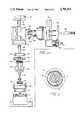
- FIG. 1is a fragmentary elevational view of the compound turret.
- FIG. 2is a cross-sectional view taken along lines 2--2in FIG. 1 and viewed in the direction of the arrows.
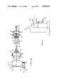
- FIG. 3is a fragmentary side elevational view of the compound turret, a portion of which is shown in cross-section and broken lines.
- FIGS. 4A and Bare exploded views of the compound turret.
- FIG. 5is an elevational view of the second embodiment of the invention.
- FIG. 6is a cross-sectional view taken along lines 6--6 in FIG. 1 and viewed in the direction of the arrows of the compound turret's harmonic drive unit.
- FIGS. 1, 2 and 5are identical to FIGS. 1, 2 and 5
- the compound turret Acomprises a base 2 mounted on carriage C.
- a turret indexing unit Iis rotatably supported on base 2.
- Turret indexing unit Ioperates to index the rotary turret L and the stationary turret D into turret operating and turret storage positions.
- the turret indexing unit Iincludes a harmonic drive unit 4 having a circular spline 6 fixed to base 2, a flexspline 8, best seen in FIG. 6, supported on a wave generator 10 and an output spline 12 in meshing engagement with flexspline 8.
- the wave generator 10 of the harmonic drive unitis drivingly connected to shaft 14.
- the output element of the harmonic drive unit 12is fixed to sleeve 16.
- the sleeve 16is rotatably supported on bearing 18. Fixed to base 2 is a bearing support sleeve 20.
- Slip coupling 22operates to disengage and engage turret indexing unit I with motor M, partially shown in FIG. 1.
- Compression spring 24biases teeth 26 into engagement with teeth 28 of intermediate shaft 30.
- a pinion 32as best seen in FIG. 2, has a plurality of cams 34 circumferentially mounted thereon. Cams 34 urge slip coupling 22 out of engagement with intermediate shaft 30.
- Rack 36has teeth formed thereon in meshing engagement with teeth on the outer circumference of pinion 32.
- Rack 36is linearly displaced by hydraulic actuator 38.
- Intermediate shaft 30is drivingly connected to output shaft 40 by way of cruciform beveled gear system 42.
- the cruciform bevel gear systemincludes four beveled gears 44, 46, 48 and 50.
- the stationary turret Dis mounted on housing H.
- the stationary turret Dincludes a turret plate 52 having a plurality of non-rotating tools 54 mounted thereon.
- a bearing support sleeve 56is fixed to turret tooling plate 52.
- the turret cover plate 58is secured to bearing support 56 by fasteners 60.
- a non-rotating tool indexing unit Foperates to index tooling mounted on the stationary turret into tool operating and tool storage positions.
- the indexing unitincludes a harmonic drive 62 similar to that disclosed in the turret indexing unit I.
- the output spline 64 of the harmonic driveis fixed to turret cover plate 58.
- the wave generator 66is drivingly connected to shaft 68.
- Circular spline 70is fixed to sleeve 72.
- Sleeve 72is rotatably supported by bearings 74.
- the indexing unit Fis disengaged and engaged from motor M by slip coupling 78.
- Spring 80acts to bias teeth 82 of slip coupling 78 into engagement with teeth 84 of intermediate shaft 76.
- a pinion 86has a plurality of cams 88 circumferentially mounted thereon. Cams 88 operate to hold slip coupling 78 out of engagement with intermediate shaft 76.
- a rack 90has a plurality of teeth formed thereon in meshing engagement with teeth formed on the outer circumference of pinion 86. The movement of rack 90 is controlled by a hydraulic actuator (not shown).
- Rotating tooling turret Lis rotatably mounted on housing H.
- a plurality of rotating tools Bare mounted on tool plate 94.
- Rotating tool drive shaft 96has a gear 98 fixed thereto.
- Shaft 96is drivingly connected to output shaft 40 of motor M through the cruciformed beveled gear system 42.
- Gear 98is in meshinq engagement with tool drive 100.
- Tooling mounted on the rotating turret Lare indexed by rotating tool indexing unit E, best seen in FIG. 3.
- the indexing unit Eis mounted on housing H.
- the indexing unit Eincludes a motor 110 which drives output shaft 118 of tachometer 112 through pulley system 114.
- Worm 120fixed to shaft 118, is in constant meshing engagement with worm wheel 102.
- Worm wheel 102is fixed to sleeve 104 which in turn is rotatably mounted on tool drive shaft 96.
- Sleeve 104is fixed to tool plate 94.
- a sensor 115 of the type well known in the artallows the operator to determine the exact position of rotating tools B and thus enables the operator to position te tools in the appropriate manner for the desired machining process.
- the sensor 115reads timing/pulley belt 116 having timing marks 117 and feeds back the appropriate position signals.
- FIG. 5A second embodiment of the invention is shown in FIG. 5.
- This embodimenthas only a single turret N.
- Rotating and non-rotating tooling 130 and 132respectively are mounted on plate 134 of the turret.
- the turret Nis indexed from a turret storage to a turret operating position by motor M 1 , in the same manner as the compound turret A shown in FIG. 1.
- the tooling mounted on plate 134are indexed by motor M 2 , in the same manner as rotating tooling L mounted on tool plate 94 of compound turret A.
- Rotating tooling 130is driven by motor M 1 through a drive connection similar to that of compound turret A shown in FIG. 1.
- Non-rotating tooling 132are positioned adjacent but are not in meshing engagement with the drive connection.
- the compound turret Aworks as follows.
- the motors M and 110 and both hydraulic actuatorsare controlled by an electronic control unit (not shown) of the type well known in the art.
- the non-rotating tooling turret Dis presently in the turret operating position. If the operator desires to index the compound turret A such that the rotating turret L is in the operating position, the motor M must be coupled to turret indexing unit I. The specific steps taken to achieve this drive connection are set forth below.
- the actuator 38is energized through the electronic control unit thus causing pinion 32 to rotate.
- Cams 34are accordingly rotated out of abutting engagement with slip coupling 22.
- the operatorwill then energize motor M through the electronic control unit.
- the output shaft 40will drive intermediate shaft 30 which will in turn impart drive to cutput shaft 14 of the turret indexing unit I through coupling 22.
- the turret indexing unit Iincludes a harmonic drive 4 which operates to index the rotary and stationary turrets L and D into turret operating and turret storage position.
- the input shaft 14drives wave generator 10.
- the flexspline 8 mounted on wave generator 10drives output member 12 which is fixed to sleeve 16.
- Sleeve 16is fixed to housing H and thus rotates housing H about its x-axis. This will result in the indexing of rotating turret L to the turret operating position and non-rotating turret D to the turret storage position.
- the harmonic drive unit 4provides high reduction ratios in a single stage. Harmonic drive units are capable of achieving reduction ratios ranging from 60:1 to 320:1 in a single stage. This feature of the harmonic drive unit allows the operator to incrementally rotate the rotating and non-rotating turrets L and D about the compound turret A's x-axis. Thus, the operator can incrementally vary the turret operating position. Accordingly, the operator can vary the angle at which a rotating or non-rotating tool strikes the work piece.
- the specifics of the harmonic drive unit 4which enables it to achieve the high reduction ratios set forth above are fully explained in the article Harmonic Drives for Servomechanisms, John H. Carlson, Chief Engineer, Harmonic Drive Division, Emhart Machinery Group, Wakefield, Mass., C 1985 by Penton/IPC. Inc. and is herein incorporated by reference.
- the operation of the non-rotating tool indexing unit Fis as follows.
- the non-rotating tool indexing unit Fis coupled and uncoupled to the motor M by slip coupling 78 in the same manner as is turret indexing unit I.
- shaft 68is coupled to intermediate shaft 76, a drive is imparted to wave generator 66.
- a flexspline mounted on the wave generator 66drives output spline 64.
- Circular spline 70is fixed to sleeve 72.
- Circular spline 70is fixed with respect to rotation of wave generator 66.
- the output spline 64is fixed to turret cover plate 58 which in turn is fixed to tooling plate 52.
- the turret tooling plate 52is rotated.
- the hydraulic actuatorwill be energized in such a manner to disengage the slip coupling 78 from intermediate shaft 76.
- Cams 88 mounted on pinion 86will act to engage teeth 75 on the outer portion of slip coupling 78 with teeth 77 on the outer portion of sleeve 72 and teeth 79 on bearing support 56.
- the harmonic drive unit 62will enable the operator to incrementally vary the tool operating position. The operator can thus vary the position that the non-rotating tool D strikes the work piece.
- harmonic drives units E and Fare not in any way used to index the rotating tools mounted on the rotating tooling turret L.
- the manner in which the rotating tooling mounted on rotating tooling turret L are indexedis fully described below.
- the operation of the rotating tool indexing unit Eis as follows.
- Motor 110drives the output shaft 118 and worm gear 120 through pulley arrangement 114.
- Worm 120is in meshing engagement with worm wheel 102.
- the electronic control unitenergizes motor 110 which imparts the drive through worm 120 to worm wheel 102 and sleeve 104 affixed thereto resulting in the rotation of tool plate 94.
- the operatordenergizes motor 110.
- the timing belt 116has a plurality of timing marks 117 formed therein. Sensing means 115 feeds back to the electronic control unit the appropriate position signals. Thus, the operator can readily obtain the exact positions of the tools mounted on the live tool plate 94.
- the worm 120 and worm wheel 102 driven by motor 110 through pulley arrangement 114enables the operator to achieve off-center machining. This is accomplished by simultaneously rotating the rotating tooling turret by way of worm 120 and worm wheel 102 and the main spindle (not shown) upon which the work piece is mounted.
- the rotating tooling mounted on the turret Lis revolving in a plane transverse to the x-axis while in abutting contact with the work piece which is similarly revolving in a plane transverse to the x-axis. In this manner, the operator can obtain off-center machining.
Landscapes
- Engineering & Computer Science (AREA)
- Mechanical Engineering (AREA)
- Cutting Tools, Boring Holders, And Turrets (AREA)
- Machine Tool Positioning Apparatuses (AREA)
Abstract
Description
Claims (21)
Priority Applications (1)
| Application Number | Priority Date | Filing Date | Title |
|---|---|---|---|
| US06/942,310US4785513A (en) | 1986-12-16 | 1986-12-16 | Turret having rotating and non-rotating tooling |
Applications Claiming Priority (1)
| Application Number | Priority Date | Filing Date | Title |
|---|---|---|---|
| US06/942,310US4785513A (en) | 1986-12-16 | 1986-12-16 | Turret having rotating and non-rotating tooling |
Publications (1)
| Publication Number | Publication Date |
|---|---|
| US4785513Atrue US4785513A (en) | 1988-11-22 |
Family
ID=25477897
Family Applications (1)
| Application Number | Title | Priority Date | Filing Date |
|---|---|---|---|
| US06/942,310Expired - Fee RelatedUS4785513A (en) | 1986-12-16 | 1986-12-16 | Turret having rotating and non-rotating tooling |
Country Status (1)
| Country | Link |
|---|---|
| US (1) | US4785513A (en) |
Cited By (29)
| Publication number | Priority date | Publication date | Assignee | Title |
|---|---|---|---|---|
| US4949443A (en)* | 1988-06-29 | 1990-08-21 | Tatsuhiko Saruwatari | Numerically controlled lathe |
| US5054176A (en)* | 1987-10-13 | 1991-10-08 | Franz Wachter | Machine tool and chucking attachment and tool head therefor |
| US5072636A (en)* | 1989-03-16 | 1991-12-17 | Ocn-Ppl S.P.A. | Tool-carrying slide for lathes |
| US5125142A (en)* | 1988-04-20 | 1992-06-30 | Hitachi Seiki Co., Ltd. | Turret head |
| US5161290A (en)* | 1990-03-22 | 1992-11-10 | Teijin Seiki Co., Ltd. | Tool-rest driving device |
| US5168614A (en)* | 1990-06-09 | 1992-12-08 | Sauter Feinmechanik Gmbh | Tool turret |
| US5188004A (en)* | 1988-12-21 | 1993-02-23 | Kabushiki Kaisha Komatsu Seisakusho | Turntable apparatus for universal machine tool |
| FR2704789A1 (en)* | 1993-05-07 | 1994-11-10 | Schleicher Didier | Revolving multi-spindle head for machine tool |
| US5386743A (en)* | 1993-07-13 | 1995-02-07 | Industrial Technology Research Institute | Turret indexing device |
| US5394335A (en)* | 1993-03-31 | 1995-02-28 | Amada Engineering & Service Co., Inc. | Retrofit auto-indexing system |
| US20030163230A1 (en)* | 1999-07-30 | 2003-08-28 | Oshkosh Truck Corporation | Turret operator interface system and method for a fire fighting vehicle |
| US20030171854A1 (en)* | 1999-07-30 | 2003-09-11 | Oshkosh Truck Corporation | Turret deployment system and method for a fire fighting vehicle |
| US6640404B2 (en)* | 2000-08-28 | 2003-11-04 | Hardinge Inc. | Three piece coupling arrangement for a turret indexing mechanism for a machine tool assembly and an air bearing assembly for the same |
| US6666109B2 (en)* | 2001-01-11 | 2003-12-23 | Tsudakoma Kogyo Kabushiki Kaisha | Indexing apparatus and method of assembling the same |
| US20040069865A1 (en)* | 2002-02-28 | 2004-04-15 | Oshkosh Truck Corporation | Turret positioning system and method for a fire fighting vehicle |
| US6785943B2 (en)* | 1998-09-04 | 2004-09-07 | Hardinge, Inc. | Indexing tool turret |
| US6922615B2 (en)* | 1999-07-30 | 2005-07-26 | Oshkosh Truck Corporation | Turret envelope control system and method for a fire fighting vehicle |
| US20050205565A1 (en)* | 2004-02-09 | 2005-09-22 | Cole Lorin R | Microwave cooking packages and methods of making thereof |
| US6949056B2 (en) | 2003-03-04 | 2005-09-27 | Hardinge Inc. | Machine tool |
| US20050229371A1 (en)* | 2004-04-20 | 2005-10-20 | Yung-Hsiang Lu | Structure of a twin disc type tool turret mechanism for CNC machines |
| US7006902B2 (en) | 1999-07-30 | 2006-02-28 | Oshkosh Truck Corporation | Control system and method for an equipment service vehicle |
| US7184862B2 (en)* | 1999-07-30 | 2007-02-27 | Oshkosh Truck Corporation | Turret targeting system and method for a fire fighting vehicle |
| US20070088469A1 (en)* | 2005-10-04 | 2007-04-19 | Oshkosh Truck Corporation | Vehicle control system and method |
| US7711460B2 (en) | 2001-01-31 | 2010-05-04 | Oshkosh Corporation | Control system and method for electric vehicle |
| US20100284756A1 (en)* | 2009-05-11 | 2010-11-11 | Tung Fu-Hsiang | Tool clamping device of tool seat |
| US7835838B2 (en) | 1999-07-30 | 2010-11-16 | Oshkosh Corporation | Concrete placement vehicle control system and method |
| EP3838455A1 (en)* | 2019-12-17 | 2021-06-23 | Ceratizit Austria Gesellschaft m.b.H. | Tool system |
| US11052463B2 (en)* | 2017-03-15 | 2021-07-06 | Citizen Watch Co., Ltd. | Turret tool post |
| WO2023033024A1 (en)* | 2021-09-01 | 2023-03-09 | Dmg森精機株式会社 | Turret, clamp state detection method, and clamp state detection program |
Citations (10)
| Publication number | Priority date | Publication date | Assignee | Title |
|---|---|---|---|---|
| US1915375A (en)* | 1930-04-25 | 1933-06-27 | Magdeburger Werkzeugmaschfab | Machine tool with reciprocating carriage |
| US2735161A (en)* | 1951-05-18 | 1956-02-21 | pulman | |
| US2748451A (en)* | 1951-05-02 | 1956-06-05 | C V A Jigs Moulds & Tools Ltd | Gear transmissions |
| US2959065A (en)* | 1958-12-10 | 1960-11-08 | United Shoe Machinery Corp | Spline and rotary table |
| US3786539A (en)* | 1969-10-16 | 1974-01-22 | Index Werke Kg Hahn & Tessky | Multiple tool turret |
| SU496159A1 (en)* | 1972-06-05 | 1975-12-25 | Division chain of the dividing machine | |
| US4080853A (en)* | 1976-03-10 | 1978-03-28 | Okuma Machinery Works, Ltd. | Numerically controlled lathe |
| DE2930965A1 (en)* | 1979-07-31 | 1981-02-05 | Sauter Kg Feinmechanik | Indexing multiple lathe tool-holder - has multistage ePicyclic gear train reversible to brake turret |
| US4644825A (en)* | 1984-04-16 | 1987-02-24 | Kabushiki Kaisha Yamazaki | Indexing and positioning device |
| JPH114648A (en)* | 1997-06-16 | 1999-01-12 | Senshin Kogyo Kk | Housing tool for nest building material |
- 1986
- 1986-12-16USUS06/942,310patent/US4785513A/ennot_activeExpired - Fee Related
Patent Citations (10)
| Publication number | Priority date | Publication date | Assignee | Title |
|---|---|---|---|---|
| US1915375A (en)* | 1930-04-25 | 1933-06-27 | Magdeburger Werkzeugmaschfab | Machine tool with reciprocating carriage |
| US2748451A (en)* | 1951-05-02 | 1956-06-05 | C V A Jigs Moulds & Tools Ltd | Gear transmissions |
| US2735161A (en)* | 1951-05-18 | 1956-02-21 | pulman | |
| US2959065A (en)* | 1958-12-10 | 1960-11-08 | United Shoe Machinery Corp | Spline and rotary table |
| US3786539A (en)* | 1969-10-16 | 1974-01-22 | Index Werke Kg Hahn & Tessky | Multiple tool turret |
| SU496159A1 (en)* | 1972-06-05 | 1975-12-25 | Division chain of the dividing machine | |
| US4080853A (en)* | 1976-03-10 | 1978-03-28 | Okuma Machinery Works, Ltd. | Numerically controlled lathe |
| DE2930965A1 (en)* | 1979-07-31 | 1981-02-05 | Sauter Kg Feinmechanik | Indexing multiple lathe tool-holder - has multistage ePicyclic gear train reversible to brake turret |
| US4644825A (en)* | 1984-04-16 | 1987-02-24 | Kabushiki Kaisha Yamazaki | Indexing and positioning device |
| JPH114648A (en)* | 1997-06-16 | 1999-01-12 | Senshin Kogyo Kk | Housing tool for nest building material |
Cited By (38)
| Publication number | Priority date | Publication date | Assignee | Title |
|---|---|---|---|---|
| US5054176A (en)* | 1987-10-13 | 1991-10-08 | Franz Wachter | Machine tool and chucking attachment and tool head therefor |
| US5125142A (en)* | 1988-04-20 | 1992-06-30 | Hitachi Seiki Co., Ltd. | Turret head |
| US4949443A (en)* | 1988-06-29 | 1990-08-21 | Tatsuhiko Saruwatari | Numerically controlled lathe |
| US5188004A (en)* | 1988-12-21 | 1993-02-23 | Kabushiki Kaisha Komatsu Seisakusho | Turntable apparatus for universal machine tool |
| US5072636A (en)* | 1989-03-16 | 1991-12-17 | Ocn-Ppl S.P.A. | Tool-carrying slide for lathes |
| US5161290A (en)* | 1990-03-22 | 1992-11-10 | Teijin Seiki Co., Ltd. | Tool-rest driving device |
| US5168614A (en)* | 1990-06-09 | 1992-12-08 | Sauter Feinmechanik Gmbh | Tool turret |
| US5394335A (en)* | 1993-03-31 | 1995-02-28 | Amada Engineering & Service Co., Inc. | Retrofit auto-indexing system |
| FR2704789A1 (en)* | 1993-05-07 | 1994-11-10 | Schleicher Didier | Revolving multi-spindle head for machine tool |
| US5386743A (en)* | 1993-07-13 | 1995-02-07 | Industrial Technology Research Institute | Turret indexing device |
| US6785943B2 (en)* | 1998-09-04 | 2004-09-07 | Hardinge, Inc. | Indexing tool turret |
| US20030171854A1 (en)* | 1999-07-30 | 2003-09-11 | Oshkosh Truck Corporation | Turret deployment system and method for a fire fighting vehicle |
| US8095247B2 (en) | 1999-07-30 | 2012-01-10 | Oshkosh Corporation | Turret envelope control system and method for a vehicle |
| US7127331B2 (en)* | 1999-07-30 | 2006-10-24 | Oshkosh Truck Corporation | Turret operator interface system and method for a fire fighting vehicle |
| US6922615B2 (en)* | 1999-07-30 | 2005-07-26 | Oshkosh Truck Corporation | Turret envelope control system and method for a fire fighting vehicle |
| US7835838B2 (en) | 1999-07-30 | 2010-11-16 | Oshkosh Corporation | Concrete placement vehicle control system and method |
| US20030163230A1 (en)* | 1999-07-30 | 2003-08-28 | Oshkosh Truck Corporation | Turret operator interface system and method for a fire fighting vehicle |
| US7006902B2 (en) | 1999-07-30 | 2006-02-28 | Oshkosh Truck Corporation | Control system and method for an equipment service vehicle |
| US7184862B2 (en)* | 1999-07-30 | 2007-02-27 | Oshkosh Truck Corporation | Turret targeting system and method for a fire fighting vehicle |
| US7162332B2 (en)* | 1999-07-30 | 2007-01-09 | Oshkosh Truck Corporation | Turret deployment system and method for a fire fighting vehicle |
| US6640404B2 (en)* | 2000-08-28 | 2003-11-04 | Hardinge Inc. | Three piece coupling arrangement for a turret indexing mechanism for a machine tool assembly and an air bearing assembly for the same |
| US6666109B2 (en)* | 2001-01-11 | 2003-12-23 | Tsudakoma Kogyo Kabushiki Kaisha | Indexing apparatus and method of assembling the same |
| US7711460B2 (en) | 2001-01-31 | 2010-05-04 | Oshkosh Corporation | Control system and method for electric vehicle |
| US7274976B2 (en) | 2002-02-28 | 2007-09-25 | Oshkosh Truck Corporation | Turret positioning system and method for a vehicle |
| US20040069865A1 (en)* | 2002-02-28 | 2004-04-15 | Oshkosh Truck Corporation | Turret positioning system and method for a fire fighting vehicle |
| US7107129B2 (en) | 2002-02-28 | 2006-09-12 | Oshkosh Truck Corporation | Turret positioning system and method for a fire fighting vehicle |
| US6949056B2 (en) | 2003-03-04 | 2005-09-27 | Hardinge Inc. | Machine tool |
| US20050205565A1 (en)* | 2004-02-09 | 2005-09-22 | Cole Lorin R | Microwave cooking packages and methods of making thereof |
| US20050229371A1 (en)* | 2004-04-20 | 2005-10-20 | Yung-Hsiang Lu | Structure of a twin disc type tool turret mechanism for CNC machines |
| US7010839B2 (en)* | 2004-04-20 | 2006-03-14 | Factory Automation Technology Co., Ltd. | Structure of a twin disc type tool turret mechanism for CNC machines |
| US20070088469A1 (en)* | 2005-10-04 | 2007-04-19 | Oshkosh Truck Corporation | Vehicle control system and method |
| US20100284756A1 (en)* | 2009-05-11 | 2010-11-11 | Tung Fu-Hsiang | Tool clamping device of tool seat |
| US11052463B2 (en)* | 2017-03-15 | 2021-07-06 | Citizen Watch Co., Ltd. | Turret tool post |
| EP3838455A1 (en)* | 2019-12-17 | 2021-06-23 | Ceratizit Austria Gesellschaft m.b.H. | Tool system |
| WO2021121783A1 (en)* | 2019-12-17 | 2021-06-24 | Ceratizit Austria Gesellschaft M.B.H. | Tool system |
| US12397354B2 (en) | 2019-12-17 | 2025-08-26 | Ceratizit Austria Gesellschaft M.B.H. | Tool system |
| WO2023033024A1 (en)* | 2021-09-01 | 2023-03-09 | Dmg森精機株式会社 | Turret, clamp state detection method, and clamp state detection program |
| JP2023035432A (en)* | 2021-09-01 | 2023-03-13 | Dmg森精機株式会社 | Turret, clamp state detection method and clamp state detection program |
Similar Documents
| Publication | Publication Date | Title |
|---|---|---|
| US4785513A (en) | Turret having rotating and non-rotating tooling | |
| US5882158A (en) | Drive assembly | |
| US2227410A (en) | Machine tool | |
| CA1207169A (en) | Contour boring machine with radial slide head | |
| US5632075A (en) | Tool-carrier turret | |
| US1744809A (en) | Universal and automatic machine tool | |
| US5257883A (en) | Operating head for automatic machine tools | |
| US9089940B2 (en) | Drive device | |
| GB1438876A (en) | Multi-spindle automatic lathe | |
| US4704926A (en) | Turret for an automatic lathe | |
| US4656708A (en) | Live tooling turret | |
| US4087891A (en) | Turret toolposter | |
| US6003409A (en) | Play-free device for driving a rotary table | |
| EP0071400A2 (en) | Servo-controlled spindle drive system | |
| EP0250609A1 (en) | Shiftable transmission motor drive with assured input-output relationship | |
| US4643037A (en) | Gear change mechanism | |
| EP0557969A1 (en) | Chuck indexing arrangement and method | |
| US5178040A (en) | Tool turret for machine tools | |
| JP2889426B2 (en) | Turret tool axis drive | |
| US4838741A (en) | Method for making an epicyclic speed reducer with two stage integral rotor | |
| JPH0513775B2 (en) | ||
| US3885280A (en) | Bi-Rotational heads mounted on milling and boring machines | |
| US2455876A (en) | Machine tool | |
| US4909682A (en) | Table positioning device for metal-cutting machine tools | |
| JPH03277405A (en) | drive device |
Legal Events
| Date | Code | Title | Description |
|---|---|---|---|
| AS | Assignment | Owner name:HARDINGE BROTHERS, INC., 1420 COLLEGE AVENUE, ELMI Free format text:ASSIGNMENT OF ASSIGNORS INTEREST.;ASSIGNORS:LEE, RICHARD C.;BROWN, IVAN R.;RAO, KAMALAKAR K.;AND OTHERS;REEL/FRAME:004646/0955;SIGNING DATES FROM 19861120 TO 19861125 | |
| FEPP | Fee payment procedure | Free format text:PAYOR NUMBER ASSIGNED (ORIGINAL EVENT CODE: ASPN); ENTITY STATUS OF PATENT OWNER: LARGE ENTITY | |
| FPAY | Fee payment | Year of fee payment:4 | |
| FEPP | Fee payment procedure | Free format text:PAYER NUMBER DE-ASSIGNED (ORIGINAL EVENT CODE: RMPN); ENTITY STATUS OF PATENT OWNER: LARGE ENTITY Free format text:PAYOR NUMBER ASSIGNED (ORIGINAL EVENT CODE: ASPN); ENTITY STATUS OF PATENT OWNER: LARGE ENTITY | |
| REMI | Maintenance fee reminder mailed | ||
| LAPS | Lapse for failure to pay maintenance fees | ||
| FP | Lapsed due to failure to pay maintenance fee | Effective date:19961127 | |
| AS | Assignment | Owner name:MANUFACTURERS AND TRADERS TRUST COMPANY, AS AGENT, Free format text:SECURITY AGREEMENT;ASSIGNOR:HARDINGE INC., F/K/A HARDINGE BROTHERS INC.;REEL/FRAME:016602/0252 Effective date:20050128 | |
| AS | Assignment | Owner name:HARDINGE, INC. (FORMERLY KNOWN AS HARDINGE BROTHER Free format text:RELEASE OF SECURITY INTEREST RECORDED AT REEL/FRAME 16602/0252, 17272/0814 AND 18700/0965;ASSIGNOR:MANUFACTURERS AND TRADERS TRUST COMPANY;REEL/FRAME:021109/0309 Effective date:20080613 | |
| STCH | Information on status: patent discontinuation | Free format text:PATENT EXPIRED DUE TO NONPAYMENT OF MAINTENANCE FEES UNDER 37 CFR 1.362 |