US4785402A - Ultrasonic imaging apparatus for color display of flow velocity - Google Patents
Ultrasonic imaging apparatus for color display of flow velocityDownload PDFInfo
- Publication number
- US4785402A US4785402AUS06/924,559US92455986AUS4785402AUS 4785402 AUS4785402 AUS 4785402AUS 92455986 AUS92455986 AUS 92455986AUS 4785402 AUS4785402 AUS 4785402A
- Authority
- US
- United States
- Prior art keywords
- velocity
- data
- zero
- color
- shift
- Prior art date
- Legal status (The legal status is an assumption and is not a legal conclusion. Google has not performed a legal analysis and makes no representation as to the accuracy of the status listed.)
- Expired - Lifetime
Links
Images


Classifications
- G—PHYSICS
- G01—MEASURING; TESTING
- G01N—INVESTIGATING OR ANALYSING MATERIALS BY DETERMINING THEIR CHEMICAL OR PHYSICAL PROPERTIES
- G01N29/00—Investigating or analysing materials by the use of ultrasonic, sonic or infrasonic waves; Visualisation of the interior of objects by transmitting ultrasonic or sonic waves through the object
- G01N29/04—Analysing solids
- G01N29/06—Visualisation of the interior, e.g. acoustic microscopy
- G01N29/0609—Display arrangements, e.g. colour displays
- A—HUMAN NECESSITIES
- A61—MEDICAL OR VETERINARY SCIENCE; HYGIENE
- A61B—DIAGNOSIS; SURGERY; IDENTIFICATION
- A61B8/00—Diagnosis using ultrasonic, sonic or infrasonic waves
- A61B8/06—Measuring blood flow
- G—PHYSICS
- G01—MEASURING; TESTING
- G01P—MEASURING LINEAR OR ANGULAR SPEED, ACCELERATION, DECELERATION, OR SHOCK; INDICATING PRESENCE, ABSENCE, OR DIRECTION, OF MOVEMENT
- G01P5/00—Measuring speed of fluids, e.g. of air stream; Measuring speed of bodies relative to fluids, e.g. of ship, of aircraft
- G01P5/24—Measuring speed of fluids, e.g. of air stream; Measuring speed of bodies relative to fluids, e.g. of ship, of aircraft by measuring the direct influence of the streaming fluid on the properties of a detecting acoustical wave
- G01P5/241—Measuring speed of fluids, e.g. of air stream; Measuring speed of bodies relative to fluids, e.g. of ship, of aircraft by measuring the direct influence of the streaming fluid on the properties of a detecting acoustical wave by using reflection of acoustical waves, i.e. Doppler-effect
- G01P5/244—Measuring speed of fluids, e.g. of air stream; Measuring speed of bodies relative to fluids, e.g. of ship, of aircraft by measuring the direct influence of the streaming fluid on the properties of a detecting acoustical wave by using reflection of acoustical waves, i.e. Doppler-effect involving pulsed waves
- G—PHYSICS
- G01—MEASURING; TESTING
- G01S—RADIO DIRECTION-FINDING; RADIO NAVIGATION; DETERMINING DISTANCE OR VELOCITY BY USE OF RADIO WAVES; LOCATING OR PRESENCE-DETECTING BY USE OF THE REFLECTION OR RERADIATION OF RADIO WAVES; ANALOGOUS ARRANGEMENTS USING OTHER WAVES
- G01S15/00—Systems using the reflection or reradiation of acoustic waves, e.g. sonar systems
- G01S15/88—Sonar systems specially adapted for specific applications
- G01S15/89—Sonar systems specially adapted for specific applications for mapping or imaging
- G01S15/8906—Short-range imaging systems; Acoustic microscope systems using pulse-echo techniques
- G01S15/8979—Combined Doppler and pulse-echo imaging systems
- G—PHYSICS
- G01—MEASURING; TESTING
- G01N—INVESTIGATING OR ANALYSING MATERIALS BY DETERMINING THEIR CHEMICAL OR PHYSICAL PROPERTIES
- G01N2291/00—Indexing codes associated with group G01N29/00
- G01N2291/02—Indexing codes associated with the analysed material
- G01N2291/028—Material parameters
- G01N2291/02836—Flow rate, liquid level
Definitions
- the present inventionrelates to an ultrasonic imaging apparatus and, more particularly, to an ultrasonic imaging apparatus having a color display function.
- Ultrasonic imaging apparatusesare used in various fields, particularly in medicine. Ultrasonic imaging apparatuses for displaying a blood flow have been developed. These apparatuses form an image of a blood flow and can display the image in color. The image, which is a motion picture, shows the direction and flow velocity of blood flow in an object to be examined. The apparatuses, however, have functional limits, and display the image of blood flowing at a velocity exceeding a predetermined value in a color different from that used for displaying the actual blood flow velocity. In order to eliminate this drawback, an ultrasonic imaging apparatus adopting a Doppler method has been developed, which displays the result of frequency analysis at a certain point by using FFT (Fast Fourier Transform).
- FFTFast Fourier Transform
- This imaging apparatushas a funcion called zero shift or base-line shift.
- this functionwhen a measurement value exceeds a display limit, it is shifted downward. For example, when a blood flow velocity which changes over time exceeds the upper limit (+MAX) of the measurement range, the exceeding portion is displayed on the lower section of the display range (upper limit +MAX to lower limit -MAX), i.e., a phenomenon called aliasing occurs. Then, an operator may misunderstand the displayed image and take it for a reverse blood flow because of aliasing. In order to prevent this, the zero line of the axis of ordinate is subjected to a zero shift in order to shift the display range in the reverse flow direction. As a result, the maximum value of the flow velocity is less than the upper limit (+MAX).
- the address of a RAMcorresponds to the flow velocity.
- datais written at an address shifted by a zero shift amount, or is read out from a memory area at an address shifted by the zero shift amount. Since a Doppler signal is sampled in synchronism with an ultrasonic rate pulse, an upper limit exists in the measurable flow velocity range, and aliasing occurs in a flow velocity component exceeding the upper limit. Aliasing in this case is expressed as a change in color of the displayed image.
- a flow velocity componentwhich should originally be displayed in red and exceeds the upper limit, is displayed in blue because of aliasing.
- the operatormay not mistake the aliasing portion displayed in blue as a reverse flow, it is preferably displayed in red.
- the blood flow directioncannot be discriminated, unlike in blood flow imaging. Therefore, ultrasonic beams are incident from various directions, thereby finding a portion at which a maximum flow velocity can be obtained.
- the incident directions of the ultrasonic beamscannot be arbitrarily set because of the shape of an ultrasonic probe or the positional relationship among internal organs of the patient, an error often occurs in the maximum flow velocity, depending on the ultrasonic beam incident angle. A portion at which the maximum flow velocity can be obtained must be measured while the sample volume position is adjusted, resulting in a very cumbersome operation.
- an echo signal obtained from echo from an object to be examinedis subjected to blood flow image processing and Doppler processing.
- a flow velocity signalis subjected to zero shift by the blood flow image processing.
- the zeroshifted flow velocity signalis compressed in accordance with the shift amount, and the compressed zeroshifted flow velocity signal is displayed in color within a possible display range.
- FIG. 1is a block diagram of an ultrasonic imaging apparatus according to an embodiment of the present invention
- FIG. 2is a circuit diagram of an arithmetic circuit section provided in the apparatus of FIG. 1;
- FIG. 3shows input and output address signal lines of a zero shift process circuit provided in the circuit of FIG. 2;
- FIGS. 4A to 4Gshow gray scale patterns stored in the zero shift process circuit
- FIGS. 5A to 5Gshow FFT representations corresponding to the gray scale patterns of FIGS. 4A to 4G;
- FIG. 6shows an image by blood flow imaging
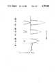
- FIG. 7shows a correspondence between an image by blood flow imaging and an image by a Doppler method.
- a 0 lineis used as a reference.
- the hue distributionis plotted along the axis of abscissa.
- the flowis plotted along the axis of ordinate.
- a forward flowis displayed on the plane above the 0 line, and a reverse flow is displayed on the plane below the 0 line. Changes in the blood flow direction and hue can be displayed in this format.
- FIG. 7shows the above representation method and a Doppler method.
- the left half of FIG. 7shows no zero shift state and the right half thereof shows a zero shift state.
- a blood flow velocityis represented by the Doppler method
- f0maximum value of the blood flow velocity
- aliasingis corrected and a maximum blood flow velocity can be displayed, as shown in the right half of FIG. 7.
- the display range of the displayed flow velocity patternappears to be increased.
- the maximum valueis expressed by a luminance prior to zero shift, it does not indicate a maximum flow velocity. Therefore, the display range after zero shift is compressed to the initial display range in accordance with the shift amount, and a flow velocity range represented by a single step is widened.
- transducer 2is driven by a drive pulse from drive circuit 1 and emits an ultrasonic beam.
- a beam reflected by the object, i.e., an echo wave,is converted into an echo signal by ultrasonic transducer 2.
- the output terminal of transducer 2is connected to receiver 3.
- Receiver 3includes a delay circuit for delaying an echo signal by a predetermined delay time and an amplifier.
- the output terminal of receiver 3is connected to the input terminals of log amplifier 4 and detector circuit 7.
- Amplifier 4 and A/D converter 5connected to its output terminal constitute tomographic image process circuit section 30. Section 30 outputs a B-Mode image signal.
- the output terminals of detector circuit 7are connected to blood flow imaging process section (or moving target indicator) 31 and ultrasonic Doppler process section 32.
- Section 31has A/D converter 12 for converting an analog output signal of detector circuit 7 into a digital signal.
- the output terminal of converter 12is connected to the input terminal of digital filter 13.
- Filter 13comprises a high pass filter having a steep filtering characteristic curve for removing clutter components from a digital signal.
- the output terminal of filter 13is connected to the input terminal of correlation circuit 14.
- the output terminal of correlation circuit 14is connected to arithmetic circuit section 15.
- Arithmetic circuit section 15has an arrangement as shown in FIG. 2 and calculates a blood flow velocity, dispersion ⁇ , and power P from an output signal from correlation circuit 14. More specifically, circuit section 15 has first and second adders 25a and 25b for receiving two signals from correlation circuit 14 which are phase-shifted from each other by 90 degrees. The output terminals of adders 25a and 25b are connected to the input terminals of divider 26. The output terminal of divider 26 is connected to zero shift process circuit 28.
- Ultrasonic Doppler process section 32has sample/hold circuit 8 for sampling/holding an echo signal from detector circuit 7 in synchronism with a drive signal from drive circuit 1.
- the output terminal of sample/hold circuit 8is connected to band pass filter 9.
- Filter 9removes any unnecessary frequency components from the output signal of circuit 8.
- the output terminal of filter 9is connected to fast Fourier transform (FFT) circuit 11 through amplifier 10.
- FFT circuit 11frequency-analyzes an output signal from amplifier 10 to form a Doppler signal.
- the output terminals to tomographic image signal circuit 30, blood flow imaging process section 31, and ultrasonic Doppler process section 32are connected to digital scan converter 6.
- the output terminal of converter 6is connected to the input terminal of color processor 16.
- Color processor 16assigns a signal (FFT digital) obtained by converter 6 to specific color data.
- color processor 16The output terminal of color processor 16 is connected to color television monitor 18 and encoder 19 through D/A converter 17.
- Encoder 19encodes an RGB television signal from processor 16 into a composite signal and supplies the composite signal to video tape recorder 20.
- the timings of digital scan converter 6 and color processor 16are controlled by controller 21.
- Drive circuit 1supplies a drive pulse signal to ultrasonic transducer 2, and transducer 2 emits an ultrasonic beam onto the object. Then, transducer 2 receives an echo from the object and supplies an echo signal to receiver 3. Receiver 3 delays and amplifies the echo signal. The output signal from receiver 3 is input to detector circuit 7 and log amplifier 4 in tomographic image signal circuit 30.
- An analog output signal from amplifier 4is converted into a digital image signal by A/D converter 5.
- the digital image signalis a B-Mode image signal.
- the echo signal input to detector circuit 7is detected and input to sample/hold circuit 8 in ultrasonic Doppler process section 32 and A/D converter 12 in blood flow imaging process section 31.
- the sampled and held signal from sample/hold circuit 8is input to FFT circuit 11 through band pass filter 9 and amplifier 10.
- FFT circuit 11transforms the output signal from filter 9 by the fast Fourier transform, and outputs a pulse Doppler signal to scan converter 6.
- An analog detection signalis converted into a digital signal by A/D converter 12, filtered by digital filter 13, and input to correlation circuit 14.
- Correlation circuit 14calculates a correlation among echo signals obtained by steering of ultrasonic beams by several times (10 to 16), and supplies an obtained output to arithmetic circuit section 15.
- Output signal fd of calculation circuit 27is input to zero shift process circuit 28.
- Process circuit 28receives a zero shift amount signal (4 bits) from an input means (not shown) and flow velocity signal fd (8 bits) and outputs zero shift flow velocity signal f0.
- Process circuit 28comprises, e.g., a ROM in practice.
- a reference leveli.e., a black level is defined as 0.
- Process circuit 28stores zero shift data corresponding to 1/8, 2/8, and 3/8 shift amounts from the 0 level toward the blue direction, and 1/8, 2/8, 3/8, and 4/8 shift amounts from the 0 level toward the red direction, as shown in FIGS. 4A to 4G.
- FIG. 4Ashows zero shift data whose shift amount is 0.
- color data of red 1st to 128th gray levelsare sequentially assigned to addresses 000 to 07F
- color data of blue 1st to 128th gray levelsare sequentially assigned to addresses 080 to 0FF.
- these memory contentsare indicated in terms of FFT representations, they correspond to the components which are not zero-shifted in FIG. 5A.
- the zero shift data shown in FIG. 4Brepresents shift amount 1/8 toward the blue direction.
- color data representing red 1st gray level to red 102nd gray levelare sequentially assigned to addresses 100 to 17F, and a red aliasing component, i.e., red 103rd gray level to red 128th gray level are stored to addresses 1DF to 1FF in the reverse order.
- Color data representing blue 1st gray level to blue 77th gray levelare sequentially assigned to addressed 180 to 1DE.
- the memory contents in this caseare displayed by FFT representation, they correspond to components which are not zero-shifted in FIG. 5B.
- the memory contents concerning zero shift amounts 1/8, 2/8, and 4/8are shown in FIGS. 4C and 4C and correspond to the FFT representations of FIGS. 5C and 5D.
- FIGS. 4E to 4Gshow memory contents respectively corresponding to the shift amounts 1/8, 2/8, and 4/8 in a case of zero shift toward the red direction. These memory contents correspond to the FFT representations of FIGS. 5E to 5G. As is apparent from the drawings, when the shift amount is 4/8, the memory stores gray scale data of either red or blue.
- zero shift process circuit 28selects a gray scale pattern shown in FIG. 4C.
- addresses 200 and 201which represent two gray levels in the case of no zero shift, represent one gray level. Namely, the range indicated by flow velocity signal fd is more compressed, compared to the case of no zero shift. It must be noted that, in the case of 2/8 zero shift, all flow velocity signals at the two adjacent addresses do not always represent one gray level, and the signal at each address representing one gray level can also be included in the memory contents in FIG. 4C.
- Gray scale (FIG. 4C) pattern datais subjected to zero shift by 2/8, and is read out from the ROM in zero shift process circuit 28 as zero shift flow velocity signal f0 which causes no aliasing.
- data representing 1st to 82nd gray levels assigned to addresses 200 to 27F and data representing 83rd to 128th gray levels assigned to addresses 2FF to 2D4are supplied to digital scan converter 6 as flow velocity signal 0.
- a Doppler signal from FFT circuit 11 in Doppler processor section 32is read in scan converter 6.
- Scan converter 6supplies this Doppler signal and flow velocity signal f0 to color processor 16.
- the Doppler signalis shifted in accordance with the zero shift amount of zero shift flow velocity signal f0 and is read out from converter 6.
- Color processor 16converts flow velocity signal f0 into a color signal, and supplies the same to color television monitor 18 through D/A converter 17 together with the Doppler signal.
- Monitor 18displays the corresponding color and Doppler signal images representing zero shift flow velocity signal f0.
- the gray scale patternsare selected in accordance with the zero shift amounts, i.e., shift amounts 1/8 and 3/8 toward the blue direction, and 1/8, 2/8, 3/8, and 4/8 toward the red direction, thereby displaying a zero shift flow velocity signal free from aliasing.
- the Doppler signal of FFT circuit 11can be read out from scan converter 6 independently from zero shift flow velocity signal f0 of zero shift process circuit 28 by controlling addressing using controller 21.
- the zero shift process circuitmay be arranged such that flow velocity signal fd obtained by velocity flow calculation circuit 27 can be read out by digital scan converter 6, and that flow velocity signal fd can be subjected to zero shift.
- Flow velocity calculation circuit 27may be omitted.
- flow velocity signal fdmay be obtained by an arithmetic calculation in advance, and a ROM, which can read out a zero shift flow velocity signal in response to the calculated data as an address signal, may be provided in zero shift process circuit 28.
Landscapes
- Physics & Mathematics (AREA)
- Engineering & Computer Science (AREA)
- Health & Medical Sciences (AREA)
- Acoustics & Sound (AREA)
- Life Sciences & Earth Sciences (AREA)
- Remote Sensing (AREA)
- Radar, Positioning & Navigation (AREA)
- General Physics & Mathematics (AREA)
- Pathology (AREA)
- General Health & Medical Sciences (AREA)
- Computer Networks & Wireless Communication (AREA)
- Biomedical Technology (AREA)
- Biochemistry (AREA)
- Analytical Chemistry (AREA)
- Chemical & Material Sciences (AREA)
- Hematology (AREA)
- Biophysics (AREA)
- Nuclear Medicine, Radiotherapy & Molecular Imaging (AREA)
- Radiology & Medical Imaging (AREA)
- Immunology (AREA)
- Heart & Thoracic Surgery (AREA)
- Medical Informatics (AREA)
- Molecular Biology (AREA)
- Surgery (AREA)
- Animal Behavior & Ethology (AREA)
- Public Health (AREA)
- Veterinary Medicine (AREA)
- Multimedia (AREA)
- Aviation & Aerospace Engineering (AREA)
- Ultra Sonic Daignosis Equipment (AREA)
Abstract
Description
fd=fr/2πtan.sup.-1 [Im{C(τ)}/Re{C(τ)}] (1)Claims (10)
Applications Claiming Priority (2)
| Application Number | Priority Date | Filing Date | Title |
|---|---|---|---|
| JP60-247796 | 1985-11-02 | ||
| JP60247796AJPH0824678B2 (en) | 1985-11-02 | 1985-11-02 | Ultrasonic diagnostic equipment |
Publications (1)
| Publication Number | Publication Date |
|---|---|
| US4785402Atrue US4785402A (en) | 1988-11-15 |
Family
ID=17168779
Family Applications (1)
| Application Number | Title | Priority Date | Filing Date |
|---|---|---|---|
| US06/924,559Expired - LifetimeUS4785402A (en) | 1985-11-02 | 1986-10-29 | Ultrasonic imaging apparatus for color display of flow velocity |
Country Status (2)
| Country | Link |
|---|---|
| US (1) | US4785402A (en) |
| JP (1) | JPH0824678B2 (en) |
Cited By (22)
| Publication number | Priority date | Publication date | Assignee | Title |
|---|---|---|---|---|
| US4911171A (en)* | 1987-06-20 | 1990-03-27 | Kabushiki Kaisha Toshiba | Ultrasonic blood flow imaging apparatus |
| US4932415A (en)* | 1988-11-14 | 1990-06-12 | Vingmed Sound A/S | Method of color coding two dimensional ulltrasonic doppler velocity images of blood flow on a display |
| US5105817A (en)* | 1988-06-08 | 1992-04-21 | Kabushiki Kaisha Toshiba | Ultrasonic bloodstream imaging apparatus |
| WO1992008408A1 (en)* | 1990-11-08 | 1992-05-29 | Prism Imaging, Inc. | Blood pool imaging and analysis using ultrasound |
| US5231573A (en)* | 1989-05-02 | 1993-07-27 | Kabushiki Kaisha Toshiba | Method and system for acquiring flow velocities in ultrasound diagnosis apparatus |
| US5249136A (en)* | 1989-12-02 | 1993-09-28 | Ezel, Inc. | System for measuring fluid-flow velocity distribution |
| US6478742B1 (en) | 1999-11-05 | 2002-11-12 | Ge Medical Systems Global Technology Company, Llc | PRF adjustment method and apparatus, and ultrasonic wave imaging apparatus |
| US6629951B2 (en) | 1999-08-05 | 2003-10-07 | Broncus Technologies, Inc. | Devices for creating collateral in the lungs |
| US6712812B2 (en) | 1999-08-05 | 2004-03-30 | Broncus Technologies, Inc. | Devices for creating collateral channels |
| US6749606B2 (en) | 1999-08-05 | 2004-06-15 | Thomas Keast | Devices for creating collateral channels |
| US20050041837A1 (en)* | 2003-08-18 | 2005-02-24 | Siemens Medical Solutions Usa, Inc. | Flow representation method and system for medical imaging |
| US7022088B2 (en) | 1999-08-05 | 2006-04-04 | Broncus Technologies, Inc. | Devices for applying energy to tissue |
| US7175644B2 (en) | 2001-02-14 | 2007-02-13 | Broncus Technologies, Inc. | Devices and methods for maintaining collateral channels in tissue |
| US7422563B2 (en) | 1999-08-05 | 2008-09-09 | Broncus Technologies, Inc. | Multifunctional tip catheter for applying energy to tissue and detecting the presence of blood flow |
| US7462162B2 (en) | 2001-09-04 | 2008-12-09 | Broncus Technologies, Inc. | Antiproliferative devices for maintaining patency of surgically created channels in a body organ |
| US7708712B2 (en) | 2001-09-04 | 2010-05-04 | Broncus Technologies, Inc. | Methods and devices for maintaining patency of surgically created channels in a body organ |
| US8409167B2 (en) | 2004-07-19 | 2013-04-02 | Broncus Medical Inc | Devices for delivering substances through an extra-anatomic opening created in an airway |
| US8709034B2 (en) | 2011-05-13 | 2014-04-29 | Broncus Medical Inc. | Methods and devices for diagnosing, monitoring, or treating medical conditions through an opening through an airway wall |
| US9345532B2 (en) | 2011-05-13 | 2016-05-24 | Broncus Medical Inc. | Methods and devices for ablation of tissue |
| US9533128B2 (en) | 2003-07-18 | 2017-01-03 | Broncus Medical Inc. | Devices for maintaining patency of surgically created channels in tissue |
| US10272260B2 (en) | 2011-11-23 | 2019-04-30 | Broncus Medical Inc. | Methods and devices for diagnosing, monitoring, or treating medical conditions through an opening through an airway wall |
| US11832877B2 (en) | 2017-04-03 | 2023-12-05 | Broncus Medical Inc. | Electrosurgical access sheath |
Families Citing this family (1)
| Publication number | Priority date | Publication date | Assignee | Title |
|---|---|---|---|---|
| JPH07284496A (en)* | 1995-03-16 | 1995-10-31 | Toshiba Corp | Ultrasonic blood flow imaging device |
Citations (16)
| Publication number | Priority date | Publication date | Assignee | Title |
|---|---|---|---|---|
| US3773033A (en)* | 1971-11-15 | 1973-11-20 | Hope City | Method and apparatus for obtaining and displaying cardiovascular data |
| US3878832A (en)* | 1973-05-14 | 1975-04-22 | Palo Alto Medical Research Fou | Method and apparatus for detecting and quantifying cardiovascular murmurs and the like |
| US4094308A (en)* | 1976-08-19 | 1978-06-13 | Cormier Cardiac Systems, Inc. | Method and system for rapid non-invasive determination of the systolic time intervals |
| US4159462A (en)* | 1977-08-18 | 1979-06-26 | General Electric Company | Ultrasonic multi-sector scanner |
| US4183046A (en)* | 1978-08-17 | 1980-01-08 | Interpretation Systems Incorporated | Electronic apparatus for converting digital image or graphics data to color video display formats and method therefor |
| US4257278A (en)* | 1979-08-24 | 1981-03-24 | General Electric Company | Quantitative volume blood flow measurement by an ultrasound imaging system featuring a Doppler modality |
| US4446872A (en)* | 1977-09-08 | 1984-05-08 | Avl Ag | Method and apparatus for determining systolic time intervals |
| US4543826A (en)* | 1982-06-03 | 1985-10-01 | The Regents Of The University Of California | Ultrasonic acoustic imaging apparatus |
| US4573477A (en)* | 1982-04-28 | 1986-03-04 | Aloka Co., Ltd. | Ultrasonic diagnostic apparatus |
| US4598589A (en)* | 1984-07-17 | 1986-07-08 | General Electric Company | Method of CW doppler imaging using variably focused ultrasonic transducer array |
| US4622634A (en)* | 1983-03-18 | 1986-11-11 | Irex Corporation | Parallel processing of simultaneous ultrasound vectors |
| US4622977A (en)* | 1983-12-05 | 1986-11-18 | Aloka Co., Ltd. | Ultrasonic diagnostic apparatus |
| US4641668A (en)* | 1982-07-28 | 1987-02-10 | Aloka Co., Ltd. | Ultrasonic blood flow imaging method and apparatus |
| US4660565A (en)* | 1983-12-08 | 1987-04-28 | Kabushiki Kaisha Toshiba | Ultrasonic imaging apparatus using pulsed Doppler signal |
| US4682229A (en)* | 1979-09-21 | 1987-07-21 | Emi Limited | Controlling the grey levels represented by a video signal |
| US4717916A (en)* | 1986-05-16 | 1988-01-05 | Holodyne Ltd., 1986 | High resolution imaging doppler interferometer |
Family Cites Families (1)
| Publication number | Priority date | Publication date | Assignee | Title |
|---|---|---|---|---|
| JPH0653118B2 (en)* | 1985-09-17 | 1994-07-20 | 株式会社島津製作所 | Display method of blood flow velocity distribution in ultrasonic diagnostic equipment |
- 1985
- 1985-11-02JPJP60247796Apatent/JPH0824678B2/ennot_activeExpired - Lifetime
- 1986
- 1986-10-29USUS06/924,559patent/US4785402A/ennot_activeExpired - Lifetime
Patent Citations (19)
| Publication number | Priority date | Publication date | Assignee | Title |
|---|---|---|---|---|
| US3773033A (en)* | 1971-11-15 | 1973-11-20 | Hope City | Method and apparatus for obtaining and displaying cardiovascular data |
| US3878832A (en)* | 1973-05-14 | 1975-04-22 | Palo Alto Medical Research Fou | Method and apparatus for detecting and quantifying cardiovascular murmurs and the like |
| US4094308A (en)* | 1976-08-19 | 1978-06-13 | Cormier Cardiac Systems, Inc. | Method and system for rapid non-invasive determination of the systolic time intervals |
| US4159462A (en)* | 1977-08-18 | 1979-06-26 | General Electric Company | Ultrasonic multi-sector scanner |
| US4446872A (en)* | 1977-09-08 | 1984-05-08 | Avl Ag | Method and apparatus for determining systolic time intervals |
| US4183046A (en)* | 1978-08-17 | 1980-01-08 | Interpretation Systems Incorporated | Electronic apparatus for converting digital image or graphics data to color video display formats and method therefor |
| US4257278A (en)* | 1979-08-24 | 1981-03-24 | General Electric Company | Quantitative volume blood flow measurement by an ultrasound imaging system featuring a Doppler modality |
| US4682229A (en)* | 1979-09-21 | 1987-07-21 | Emi Limited | Controlling the grey levels represented by a video signal |
| US4573477A (en)* | 1982-04-28 | 1986-03-04 | Aloka Co., Ltd. | Ultrasonic diagnostic apparatus |
| US4573477B1 (en)* | 1982-04-28 | 1991-10-22 | Aloka Co Ltd | |
| US4543826A (en)* | 1982-06-03 | 1985-10-01 | The Regents Of The University Of California | Ultrasonic acoustic imaging apparatus |
| US4641668A (en)* | 1982-07-28 | 1987-02-10 | Aloka Co., Ltd. | Ultrasonic blood flow imaging method and apparatus |
| US4641668B1 (en)* | 1982-07-28 | 1991-12-24 | Aloka Co Ltd | |
| US4622634A (en)* | 1983-03-18 | 1986-11-11 | Irex Corporation | Parallel processing of simultaneous ultrasound vectors |
| US4622977A (en)* | 1983-12-05 | 1986-11-18 | Aloka Co., Ltd. | Ultrasonic diagnostic apparatus |
| US4622977B1 (en)* | 1983-12-05 | 1992-01-07 | Aloka Co Ltd | |
| US4660565A (en)* | 1983-12-08 | 1987-04-28 | Kabushiki Kaisha Toshiba | Ultrasonic imaging apparatus using pulsed Doppler signal |
| US4598589A (en)* | 1984-07-17 | 1986-07-08 | General Electric Company | Method of CW doppler imaging using variably focused ultrasonic transducer array |
| US4717916A (en)* | 1986-05-16 | 1988-01-05 | Holodyne Ltd., 1986 | High resolution imaging doppler interferometer |
Non-Patent Citations (8)
| Title |
|---|
| "Real-Time Two-Dimensional Blood Flow Imaging Using an Autocorrelation Technique", by Chihiro Kasai, Koroku Namekawa, Akira Koyano, and Ryozo Omoto, IEEE Transactions on Sonics and Ultrasonics, vol. SU-32, No. 3, May 1985, pp. 458-464. |
| "Systolic Time Intervals," Noninvasive Cardiology, R. P. Lewis et al., chap. 6, pp. 301-368 (1974). |
| Real Time Two Dimensional Blood Flow Imaging Using an Autocorrelation Technique , by Chihiro Kasai, Koroku Namekawa, Akira Koyano, and Ryozo Omoto, IEEE Transactions on Sonics and Ultrasonics, vol. SU 32, No. 3, May 1985, pp. 458 464.* |
| Systolic Time Intervals, Noninvasive Cardiology, R. P. Lewis et al., chap. 6, pp. 301 368 (1974).* |
| T. Spoto et al., "Microprocessor Based Real-Time Systolic Time Interval System," Proceedings of the 7th New England Bioeng. Conference, Troy, NY (Nov. 22-23, 1979) pp. 9-12. |
| T. Spoto et al., Microprocessor Based Real Time Systolic Time Interval System, Proceedings of the 7th New England Bioeng. Conference, Troy, NY (Nov. 22 23, 1979) pp. 9 12.* |
| Y. E. Langlois et al., "Computer Based Pattern Recognition of Carotid Artery Doppler Signals for Disease Classification: Prospective Validation," Ultrasound in Medicine and Biology, vol. 10, No. 5, pp. 581-595 (1984). |
| Y. E. Langlois et al., Computer Based Pattern Recognition of Carotid Artery Doppler Signals for Disease Classification: Prospective Validation, Ultrasound in Medicine and Biology, vol. 10, No. 5, pp. 581 595 (1984).* |
Cited By (37)
| Publication number | Priority date | Publication date | Assignee | Title |
|---|---|---|---|---|
| US4911171A (en)* | 1987-06-20 | 1990-03-27 | Kabushiki Kaisha Toshiba | Ultrasonic blood flow imaging apparatus |
| US5105817A (en)* | 1988-06-08 | 1992-04-21 | Kabushiki Kaisha Toshiba | Ultrasonic bloodstream imaging apparatus |
| US4932415A (en)* | 1988-11-14 | 1990-06-12 | Vingmed Sound A/S | Method of color coding two dimensional ulltrasonic doppler velocity images of blood flow on a display |
| US5231573A (en)* | 1989-05-02 | 1993-07-27 | Kabushiki Kaisha Toshiba | Method and system for acquiring flow velocities in ultrasound diagnosis apparatus |
| US5249136A (en)* | 1989-12-02 | 1993-09-28 | Ezel, Inc. | System for measuring fluid-flow velocity distribution |
| WO1992008408A1 (en)* | 1990-11-08 | 1992-05-29 | Prism Imaging, Inc. | Blood pool imaging and analysis using ultrasound |
| US5211169A (en)* | 1990-11-08 | 1993-05-18 | Prism Imaging, Inc. | Blood pool imaging and analysis technique using ultrasound |
| US6629951B2 (en) | 1999-08-05 | 2003-10-07 | Broncus Technologies, Inc. | Devices for creating collateral in the lungs |
| US6692494B1 (en) | 1999-08-05 | 2004-02-17 | Broncus Technologies, Inc. | Methods and devices for creating collateral channels in the lungs |
| US6712812B2 (en) | 1999-08-05 | 2004-03-30 | Broncus Technologies, Inc. | Devices for creating collateral channels |
| US6749606B2 (en) | 1999-08-05 | 2004-06-15 | Thomas Keast | Devices for creating collateral channels |
| US7022088B2 (en) | 1999-08-05 | 2006-04-04 | Broncus Technologies, Inc. | Devices for applying energy to tissue |
| US7393330B2 (en) | 1999-08-05 | 2008-07-01 | Broncus Technologies, Inc. | Electrosurgical device having hollow tissue cutting member and transducer assembly |
| US7422563B2 (en) | 1999-08-05 | 2008-09-09 | Broncus Technologies, Inc. | Multifunctional tip catheter for applying energy to tissue and detecting the presence of blood flow |
| US6478742B1 (en) | 1999-11-05 | 2002-11-12 | Ge Medical Systems Global Technology Company, Llc | PRF adjustment method and apparatus, and ultrasonic wave imaging apparatus |
| US7175644B2 (en) | 2001-02-14 | 2007-02-13 | Broncus Technologies, Inc. | Devices and methods for maintaining collateral channels in tissue |
| US7708712B2 (en) | 2001-09-04 | 2010-05-04 | Broncus Technologies, Inc. | Methods and devices for maintaining patency of surgically created channels in a body organ |
| US7462162B2 (en) | 2001-09-04 | 2008-12-09 | Broncus Technologies, Inc. | Antiproliferative devices for maintaining patency of surgically created channels in a body organ |
| US9533128B2 (en) | 2003-07-18 | 2017-01-03 | Broncus Medical Inc. | Devices for maintaining patency of surgically created channels in tissue |
| US7536043B2 (en) | 2003-08-18 | 2009-05-19 | Siemens Medical Solutions Usa, Inc. | Flow representation method and system for medical imaging |
| US20050041837A1 (en)* | 2003-08-18 | 2005-02-24 | Siemens Medical Solutions Usa, Inc. | Flow representation method and system for medical imaging |
| US10369339B2 (en) | 2004-07-19 | 2019-08-06 | Broncus Medical Inc. | Devices for delivering substances through an extra-anatomic opening created in an airway |
| US8784400B2 (en) | 2004-07-19 | 2014-07-22 | Broncus Medical Inc. | Devices for delivering substances through an extra-anatomic opening created in an airway |
| US11357960B2 (en) | 2004-07-19 | 2022-06-14 | Broncus Medical Inc. | Devices for delivering substances through an extra-anatomic opening created in an airway |
| US8409167B2 (en) | 2004-07-19 | 2013-04-02 | Broncus Medical Inc | Devices for delivering substances through an extra-anatomic opening created in an airway |
| US8608724B2 (en) | 2004-07-19 | 2013-12-17 | Broncus Medical Inc. | Devices for delivering substances through an extra-anatomic opening created in an airway |
| US9913969B2 (en) | 2006-10-05 | 2018-03-13 | Broncus Medical Inc. | Devices for delivering substances through an extra-anatomic opening created in an airway |
| US9993306B2 (en) | 2011-05-13 | 2018-06-12 | Broncus Medical Inc. | Methods and devices for diagnosing, monitoring, or treating medical conditions through an opening through an airway wall |
| US9486229B2 (en) | 2011-05-13 | 2016-11-08 | Broncus Medical Inc. | Methods and devices for excision of tissue |
| US8709034B2 (en) | 2011-05-13 | 2014-04-29 | Broncus Medical Inc. | Methods and devices for diagnosing, monitoring, or treating medical conditions through an opening through an airway wall |
| US9421070B2 (en) | 2011-05-13 | 2016-08-23 | Broncus Medical Inc. | Methods and devices for diagnosing, monitoring, or treating medical conditions through an opening through an airway wall |
| US9345532B2 (en) | 2011-05-13 | 2016-05-24 | Broncus Medical Inc. | Methods and devices for ablation of tissue |
| US10631938B2 (en) | 2011-05-13 | 2020-04-28 | Broncus Medical Inc. | Methods and devices for diagnosing, monitoring, or treating medical conditions through an opening through an airway wall |
| US8932316B2 (en) | 2011-05-13 | 2015-01-13 | Broncus Medical Inc. | Methods and devices for diagnosing, monitoring, or treating medical conditions through an opening through an airway wall |
| US12016640B2 (en) | 2011-05-13 | 2024-06-25 | Broncus Medical Inc. | Methods and devices for diagnosing, monitoring, or treating medical conditions through an opening through an airway wall |
| US10272260B2 (en) | 2011-11-23 | 2019-04-30 | Broncus Medical Inc. | Methods and devices for diagnosing, monitoring, or treating medical conditions through an opening through an airway wall |
| US11832877B2 (en) | 2017-04-03 | 2023-12-05 | Broncus Medical Inc. | Electrosurgical access sheath |
Also Published As
| Publication number | Publication date |
|---|---|
| JPH0824678B2 (en) | 1996-03-13 |
| JPS62106746A (en) | 1987-05-18 |
Similar Documents
| Publication | Publication Date | Title |
|---|---|---|
| US4785402A (en) | Ultrasonic imaging apparatus for color display of flow velocity | |
| US4993417A (en) | Method and system for controlling ultrasound scanning sequence | |
| US6126605A (en) | Ultrasound color flow display optimization by adjusting dynamic range | |
| US5282471A (en) | Ultrasonic imaging system capable of displaying 3-dimensional angiogram in real time mode | |
| EP0100094B1 (en) | Ultrasonic blood flow imaging method and apparatus | |
| US6017309A (en) | Ultrasound color flow display optimization by adjusting color maps | |
| JPH0866397A (en) | Ultrasonic diagnostic equipment | |
| US5163434A (en) | Ultrasonic diagnostic apparatus | |
| US5301670A (en) | Ultrasonic diagnosis apparatus | |
| US5188113A (en) | Ultrasonic diagnosis apparatus | |
| US5394874A (en) | Angiography using ultrasound | |
| US4768515A (en) | Ultrasonic blood flow imaging apparatus | |
| US4787395A (en) | Blood flow measuring apparatus | |
| US4911171A (en) | Ultrasonic blood flow imaging apparatus | |
| US6120451A (en) | Ultrasound color flow display optimization by adjustment of threshold | |
| US5305753A (en) | Method and apparatus for determining the velocity of a flowing liquid | |
| EP0367826B1 (en) | Pulse doppler mti apparatus | |
| US5865752A (en) | Method and apparatus for ultrasound imaging using normalized difference between successive frames | |
| US5083566A (en) | Ultrasonic imaging apparatus | |
| EP1060406B1 (en) | Ultrasound color flow display optimization by adjustment of threshold using sampling | |
| JP2931707B2 (en) | Ultrasound diagnostic equipment | |
| US5081996A (en) | Ultrasonic imaging apparatus | |
| EP0577982B1 (en) | Ultrasonic imaging system | |
| JP2782905B2 (en) | Ultrasound diagnostic equipment | |
| JP2006314807A (en) | Ultrasonic diagnostic equipment |
Legal Events
| Date | Code | Title | Description |
|---|---|---|---|
| AS | Assignment | Owner name:KABUSHIKI KAISHA TOSHIBA, 72 HORIKAWA-CHO, SAIWAI- Free format text:ASSIGNMENT OF ASSIGNORS INTEREST.;ASSIGNORS:MATSUO, SATOSHI;MIYAJIMA, YASUO;REEL/FRAME:004623/0551 Effective date:19861022 | |
| STCF | Information on status: patent grant | Free format text:PATENTED CASE | |
| FEPP | Fee payment procedure | Free format text:PAYOR NUMBER ASSIGNED (ORIGINAL EVENT CODE: ASPN); ENTITY STATUS OF PATENT OWNER: LARGE ENTITY | |
| FEPP | Fee payment procedure | Free format text:PAYOR NUMBER ASSIGNED (ORIGINAL EVENT CODE: ASPN); ENTITY STATUS OF PATENT OWNER: LARGE ENTITY Free format text:PAYER NUMBER DE-ASSIGNED (ORIGINAL EVENT CODE: RMPN); ENTITY STATUS OF PATENT OWNER: LARGE ENTITY | |
| REFU | Refund | Free format text:REFUND OF EXCESS PAYMENTS PROCESSED (ORIGINAL EVENT CODE: R169); ENTITY STATUS OF PATENT OWNER: LARGE ENTITY | |
| FPAY | Fee payment | Year of fee payment:4 | |
| FPAY | Fee payment | Year of fee payment:8 | |
| FPAY | Fee payment | Year of fee payment:12 | |
| AS | Assignment | Owner name:KABUSHIKI KAISHA TOSHIBA, JAPAN Free format text:ADDRESS CHANGE EFFECTIVE JULY 10, 2001;ASSIGNOR:KABUSHIKI KAISHA TOSHIBA;REEL/FRAME:016480/0735 Effective date:20010710 Owner name:KABUSHIKI KAISHA TOSHIBA (PART INTEREST), JAPAN Free format text:ASSIGNMENT OF ASSIGNORS INTEREST;ASSIGNOR:TOSHIBA MEDICAL SYSTEMS CORPORATION;REEL/FRAME:016480/0959 Effective date:20050218 Owner name:TOSHIBA MEDICAL SYSTEMS CORPORATION, JAPAN Free format text:ASSIGNMENT OF ASSIGNORS INTEREST;ASSIGNOR:KABUSHIKI KAISHA TOSHIBA;REEL/FRAME:016480/0963 Effective date:20050209 |