US4785306A - Dual frequency feed satellite antenna horn - Google Patents
Dual frequency feed satellite antenna hornDownload PDFInfo
- Publication number
- US4785306A US4785306AUS06/819,679US81967986AUS4785306AUS 4785306 AUS4785306 AUS 4785306AUS 81967986 AUS81967986 AUS 81967986AUS 4785306 AUS4785306 AUS 4785306A
- Authority
- US
- United States
- Prior art keywords
- frequency
- feed horn
- band
- arrangement
- signals
- Prior art date
- Legal status (The legal status is an assumption and is not a legal conclusion. Google has not performed a legal analysis and makes no representation as to the accuracy of the status listed.)
- Expired - Lifetime
Links
Images

Classifications
- H—ELECTRICITY
- H04—ELECTRIC COMMUNICATION TECHNIQUE
- H04B—TRANSMISSION
- H04B7/00—Radio transmission systems, i.e. using radiation field
- H04B7/14—Relay systems
- H04B7/15—Active relay systems
- H04B7/185—Space-based or airborne stations; Stations for satellite systems
- H04B7/1851—Systems using a satellite or space-based relay
- H04B7/18519—Operations control, administration or maintenance
- H—ELECTRICITY
- H01—ELECTRIC ELEMENTS
- H01Q—ANTENNAS, i.e. RADIO AERIALS
- H01Q5/00—Arrangements for simultaneous operation of antennas on two or more different wavebands, e.g. dual-band or multi-band arrangements
- H01Q5/40—Imbricated or interleaved structures; Combined or electromagnetically coupled arrangements, e.g. comprising two or more non-connected fed radiating elements
- H01Q5/45—Imbricated or interleaved structures; Combined or electromagnetically coupled arrangements, e.g. comprising two or more non-connected fed radiating elements using two or more feeds in association with a common reflecting, diffracting or refracting device
- H01Q5/47—Imbricated or interleaved structures; Combined or electromagnetically coupled arrangements, e.g. comprising two or more non-connected fed radiating elements using two or more feeds in association with a common reflecting, diffracting or refracting device with a coaxial arrangement of the feeds
Definitions
- This inventionrelates to satellite antenna horns and particularly to a satellite antenna feed horn arrangement for receiving both C-band and Ku-band signals.
- LNAlow noise amplifier
- the present inventionprovides a feed horn arrangement to permit separate C-band and Ku-band LNB's to be mounted on a single dish without cross interference.
- the feed horn arrangement of the present inventionincludes a dielectric rod mounted within the pre-existing C-band waveguide to direct Ku-band signals to a separate Ku-band feed horn and LNB.
- the Ku-band waveguidehas no effect on the C-band signals which are amplified by the standard C-band LNA.
- the dielectric rod waveguidemay be either straight or curved depending on the configuration of the C-band amplifiers and polarizers.
- FIG. 1is a partial sectional drawing of a first embodiment of a satellite antenna feed horn arrangement constructed in accordance with the present invention.
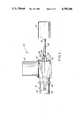
- FIG. 2is a partial sectional view of a satellite antenna feed horn arrangement constructed in accordance with a second embodiment of the invention.
- FIG. 1illustrates a first embodiment of a feed horn arrangement 10 for providing both C- and Ku-band reception to a single satellite antenna or dish.
- This embodimentincludes an "Andrews" single plane polarizing C-band coaxial waveguide or feed horn 12, whose rear portion 14 mounts a C-band LNA 16. The entire assembly is mounted at the focus of a satellite dish (not shown).
- a Ku-band (12 GHz) wave guideis formed by a relatively small diameter rod of dielectric material.
- One suitable dielectric materialis tetraflouroethylene plastic (Teflon) although other dielectric materials may also be used.
- the appropriate diameter for such a rodis a function of the dielectric constant e of the material.
- the dielectric rod diameteris equal to the diameter of a hollow tubular waveguide for the Ku-band (0.625 inches) divided by the dielectric constant (2.1) of teflon:
- the appropriate diameter for a Ku band Teflon waveguideis approximately 0.30 inches which may be approximated by a 5/16 inch (0.3125) diameter rod.
- a rod of this diameteris considerably smaller than the inner diameter of a C-band feed horn and thus will easily fit within it. Because the rear portion 14 of waveguide 12 mounts LNA 16 at a right angle to its longitudinal axis there is no reception equipment located at its rear wall 18. Accordingly, Ku-band reception apparatus may be readily located at rear wall 18.
- a 5/16" diameter teflon rod 20is mounted within C-band coaxial waveguide 12 and extends through and out of rear portion 14 through an aperture 21 disposed in rear wall 18.
- the forward portion 22 of rod 20is mounted and centered within waveguide 12 by means of dielectric annular mounting disks 24 which engage the inner surface of waveguide 12.
- the rearward portion 25 of rod 20, extending out of polarizer 14,terminates in a tapered tip 26.
- Feed horn 28includes a cylindrical forward portion 32 for mounting within aperture 21, a conical portion 34 and a cylindrical rear portion 36 joined to LNB 30.
- Conical portion 34 of feed horn 28tapers from a diameter of approximately 1.025 inches to the 0.625 inch diameter of the rear portion 36 of Ku-band feed horn 28.
- the length of rod 20is such that tapered tip 26 is located at conical portion 34 of feed horn 28 to insure that the Ku-band wave is properly launched into feed horn 28.
- Rod 20should be centered within Ku-band feed horn 12 to provide maximum signal strength. No substantial signal deterioration will occur if annular mounting disks 24 are constructed of teflon and have a thickness on the order of 1/16 inch.
- both Ku-band and C-band signalsare reflected from the satellite dish and enter feed horn 12.
- the C-band signalswill travel through C-band feed horn 12 and will be directed by rear portion 14 into C-band LNA 16.
- the Ku-band signalswill follow dielectric rod 20 back through rear wall 18 and be launched into Ku-band feed horn 28 for amplification by Ku-band LNB 30.
- rod 20is substantially transparent to C-band signals its presence within waveguide 12 has essentially no effect on C-band signals.
- feed horn arrangement 10enables reception of both C- and Ku-band signals by a single antenna with the different frequency signals being directed to the appropriate amplifier.
- Feed horn arrangement 10 as illustrated in FIG. 1is particularly suitable for a use with C-band equipment having a single plane polarizing feed horn as the LNA is disposed at right angles.
- this approachis not practicable in C-band systems utilizing switchable dual-plane polarizers which mount C-band LNA along the longitudinal axis of the C-band feed horn.
- the feed horn arrangement 50 illustrated in FIG. 2is used.
- Feed horn arrangement 50includes a standard C-band waveguide or feed horn 52, a switchable dual plane polarizer 54 at the rearward end of feed horn 52 and a C-band LNA or LNB 56 mounted to the rear of polarizer 54. Since LNA 56 is located at the rear of polarizer 54, any Ku-band signal must be directed away from the longitudinal axis 57 of feed horn 52. This is accomplished by a curved dielectric rod 60 which directs the Ku-band signals outside of C-band feed horn 52. Rod 60 is a teflon rod of 5/16" diameter as discussed above.
- the forward end 61 of rod 60is mounted within feed horn 52 by a pair of annular dielectric mounting disks 64 which engage the inner surface of feed horn 52.
- the central portion 62 of rod 60is curved away from the longitudinal axis 57 of feed horn 52 at an angle of approximately 55°.
- the rear portion 68 of rod 60exits and extends out of feed horn 52 through an aperture 70 disposed in the side of feed horn 52.
- Rear portion 68 of rod 60terminates in a tapered tip 69 to insure optimal launching of the Ku-band signal.
- a metallic Ku-band feed horn 71which includes a conical forward portion 72 similar to portion 34 of waveguide 26 as described above.
- An annular dielectric mounting disk 74serves to center rear portion 68 of rod 60 within feed horn 71. Tapered tip 69 of rod 60 is positioned within conical portion 72 of feed horn 71 to optimize the transition of the Ku-band signal from rod 60 to feed horn 71.
- Feed horn 71has a diameter of 0.625 inches and includes a curved rearward portion 76 which permits Ku-band LNB 58 to be positioned parallel to C-band LNA 56 so as to minimize shadowing of the satellite disk.
- the 55° angle of curvature between rear portion 68 of rod 60 and the longitudinal axis 57 of feed horn 52causes no significant Ku-band signal loss.
- the plane of curvature of rod 60is optimally disposed at a 45° angle to the polarization planes of polarizer 54.
- feed horn arrangement 50 of FIG. 2minimizes signal deterioration of both the C- and Ku-band signals by the waveguide of the other frequency. Accordingly, both the C-band and Ku-band signals are routed to their respected amplifiers without interference to optimize reception of both satellite bands.
Landscapes
- Physics & Mathematics (AREA)
- Engineering & Computer Science (AREA)
- Electromagnetism (AREA)
- Astronomy & Astrophysics (AREA)
- Aviation & Aerospace Engineering (AREA)
- General Physics & Mathematics (AREA)
- Computer Networks & Wireless Communication (AREA)
- Signal Processing (AREA)
- Waveguide Aerials (AREA)
Abstract
Description
d.sub.rod =0.625/e=0.625/2.1=0.30"
Claims (12)
Priority Applications (1)
| Application Number | Priority Date | Filing Date | Title |
|---|---|---|---|
| US06/819,679US4785306A (en) | 1986-01-17 | 1986-01-17 | Dual frequency feed satellite antenna horn |
Applications Claiming Priority (1)
| Application Number | Priority Date | Filing Date | Title |
|---|---|---|---|
| US06/819,679US4785306A (en) | 1986-01-17 | 1986-01-17 | Dual frequency feed satellite antenna horn |
Publications (1)
| Publication Number | Publication Date |
|---|---|
| US4785306Atrue US4785306A (en) | 1988-11-15 |
Family
ID=25228759
Family Applications (1)
| Application Number | Title | Priority Date | Filing Date |
|---|---|---|---|
| US06/819,679Expired - LifetimeUS4785306A (en) | 1986-01-17 | 1986-01-17 | Dual frequency feed satellite antenna horn |
Country Status (1)
| Country | Link |
|---|---|
| US (1) | US4785306A (en) |
Cited By (39)
| Publication number | Priority date | Publication date | Assignee | Title |
|---|---|---|---|---|
| US4910527A (en)* | 1987-07-07 | 1990-03-20 | Janiel Corporation | Configurable KU-band receiver for satellite antenna feed |
| US5005023A (en)* | 1988-12-01 | 1991-04-02 | Gardiner Communications Corporation | Dual band integrated LNB feedhorn system |
| US5103237A (en)* | 1988-10-05 | 1992-04-07 | Chaparral Communications | Dual band signal receiver |
| US5109232A (en)* | 1990-02-20 | 1992-04-28 | Andrew Corporation | Dual frequency antenna feed with apertured channel |
| US5255003A (en)* | 1987-10-02 | 1993-10-19 | Antenna Downlink, Inc. | Multiple-frequency microwave feed assembly |
| US5461394A (en)* | 1992-02-24 | 1995-10-24 | Chaparral Communications Inc. | Dual band signal receiver |
| US5635944A (en)* | 1994-12-15 | 1997-06-03 | Unisys Corporation | Multi-band antenna feed with switchably shared I/O port |
| US5774788A (en)* | 1995-03-17 | 1998-06-30 | Hughes Electronics | Remote ground terminal having an outdoor unit with a frequency-multiplier |
| US5812096A (en)* | 1995-10-10 | 1998-09-22 | Hughes Electronics Corporation | Multiple-satellite receive antenna with siamese feedhorn |
| US6208309B1 (en) | 1999-03-16 | 2001-03-27 | Trw Inc. | Dual depth aperture chokes for dual frequency horn equalizing E and H-plane patterns |
| US6266025B1 (en) | 2000-01-12 | 2001-07-24 | Hrl Laboratories, Llc | Coaxial dielectric rod antenna with multi-frequency collinear apertures |
| US6501433B2 (en) | 2000-01-12 | 2002-12-31 | Hrl Laboratories, Llc | Coaxial dielectric rod antenna with multi-frequency collinear apertures |
| US6522635B1 (en) | 1995-06-15 | 2003-02-18 | Mobile Satellite Ventures, Lp | Communication protocol for satellite data processing |
| US20040257300A1 (en)* | 2003-06-20 | 2004-12-23 | Hrl Laboratories, Llc | Wave antenna lens system |
| US7142809B1 (en) | 2001-02-27 | 2006-11-28 | The Directv Group, Inc. | Device and method to locally fill gaps in spotbeam satellite systems with frequency re-use |
| US20070250909A1 (en)* | 2005-09-02 | 2007-10-25 | The Directv Group, Inc. | Network fraud prevention via registration and verification |
| US20100188305A1 (en)* | 2009-01-29 | 2010-07-29 | Bruce Larry Blaser | Waveguide polarizers |
| US7900230B2 (en) | 2005-04-01 | 2011-03-01 | The Directv Group, Inc. | Intelligent two-way switching network |
| US7945932B2 (en) | 2005-04-01 | 2011-05-17 | The Directv Group, Inc. | Narrow bandwidth signal delivery system |
| US7950038B2 (en) | 2005-04-01 | 2011-05-24 | The Directv Group, Inc. | Transponder tuning and mapping |
| US7954127B2 (en) | 2002-09-25 | 2011-05-31 | The Directv Group, Inc. | Direct broadcast signal distribution methods |
| US7958531B2 (en) | 2005-04-01 | 2011-06-07 | The Directv Group, Inc. | Automatic level control for incoming signals of different signal strengths |
| US7987486B2 (en) | 2005-04-01 | 2011-07-26 | The Directv Group, Inc. | System architecture for control and signal distribution on coaxial cable |
| US7991348B2 (en) | 2005-10-12 | 2011-08-02 | The Directv Group, Inc. | Triple band combining approach to satellite signal distribution |
| US8019275B2 (en) | 2005-10-12 | 2011-09-13 | The Directv Group, Inc. | Band upconverter approach to KA/KU signal distribution |
| US8024759B2 (en) | 2005-04-01 | 2011-09-20 | The Directv Group, Inc. | Backwards-compatible frequency translation module for satellite video delivery |
| US8229383B2 (en) | 2009-01-06 | 2012-07-24 | The Directv Group, Inc. | Frequency drift estimation for low cost outdoor unit frequency conversions and system diagnostics |
| US8238813B1 (en) | 2007-08-20 | 2012-08-07 | The Directv Group, Inc. | Computationally efficient design for broadcast satellite single wire and/or direct demod interface |
| US8549565B2 (en) | 2005-04-01 | 2013-10-01 | The Directv Group, Inc. | Power balancing signal combiner |
| US8621525B2 (en) | 2005-04-01 | 2013-12-31 | The Directv Group, Inc. | Signal injection via power supply |
| US8712318B2 (en) | 2007-05-29 | 2014-04-29 | The Directv Group, Inc. | Integrated multi-sat LNB and frequency translation module |
| US8719875B2 (en) | 2006-11-06 | 2014-05-06 | The Directv Group, Inc. | Satellite television IP bitstream generator receiving unit |
| US8789115B2 (en) | 2005-09-02 | 2014-07-22 | The Directv Group, Inc. | Frequency translation module discovery and configuration |
| US20140227905A1 (en)* | 2013-02-13 | 2014-08-14 | Bradley David Knott | Device and method for impedance matching microwave coaxial line discontinuities |
| US9026106B2 (en) | 2012-02-06 | 2015-05-05 | Foundation Telecommunications, Inc. | Hybrid dual-band satellite communication system |
| US9648568B2 (en) | 2012-02-06 | 2017-05-09 | Foundation Telecommunications, Inc. | Hybrid dual-band satellite communication system |
| US9942618B2 (en) | 2007-10-31 | 2018-04-10 | The Directv Group, Inc. | SMATV headend using IP transport stream input and method for operating the same |
| US20190288394A1 (en)* | 2018-03-19 | 2019-09-19 | Mti Wireless Edge, Ltd. | Feed for dual band antenna |
| US12184391B2 (en) | 2020-04-10 | 2024-12-31 | Landmark Pegasus Inc. | Multi-band signal communications system and method |
Citations (11)
| Publication number | Priority date | Publication date | Assignee | Title |
|---|---|---|---|---|
| US3389394A (en)* | 1965-11-26 | 1968-06-18 | Radiation Inc | Multiple frequency antenna |
| US3438041A (en)* | 1965-09-15 | 1969-04-08 | Andrew Corp | Parabolic reflector with dual cross-polarized feeds of different frequencies |
| US3500419A (en)* | 1966-09-09 | 1970-03-10 | Technical Appliance Corp | Dual frequency,dual polarized cassegrain antenna |
| US3523297A (en)* | 1968-12-20 | 1970-08-04 | Hughes Aircraft Co | Dual frequency antenna |
| US4083050A (en)* | 1976-09-01 | 1978-04-04 | The Bendix Corporation | Dual band monopole omni antenna |
| US4274097A (en)* | 1975-03-25 | 1981-06-16 | The United States Of America As Represented By The Secretary Of The Navy | Embedded dielectric rod antenna |
| US4282527A (en)* | 1979-06-11 | 1981-08-04 | General Dynamics, Pomona Division | Multi-spectral detection system with common collecting means |
| US4287519A (en)* | 1980-04-04 | 1981-09-01 | The United States Of America As Represented By The Secretary Of The Navy | Multi-mode Luneberg lens antenna |
| US4297707A (en)* | 1976-06-30 | 1981-10-27 | Siemens Aktiengesellschaft | Multiple omnidirectional antenna |
| US4482899A (en)* | 1981-10-28 | 1984-11-13 | At&T Bell Laboratories | Wide bandwidth hybrid mode feeds |
| US4630059A (en)* | 1983-06-18 | 1986-12-16 | Ant Nachrichtentechnik Gmbh | Four-port network coupling arrangement for microwave antennas employing monopulse tracking |
- 1986
- 1986-01-17USUS06/819,679patent/US4785306A/ennot_activeExpired - Lifetime
Patent Citations (11)
| Publication number | Priority date | Publication date | Assignee | Title |
|---|---|---|---|---|
| US3438041A (en)* | 1965-09-15 | 1969-04-08 | Andrew Corp | Parabolic reflector with dual cross-polarized feeds of different frequencies |
| US3389394A (en)* | 1965-11-26 | 1968-06-18 | Radiation Inc | Multiple frequency antenna |
| US3500419A (en)* | 1966-09-09 | 1970-03-10 | Technical Appliance Corp | Dual frequency,dual polarized cassegrain antenna |
| US3523297A (en)* | 1968-12-20 | 1970-08-04 | Hughes Aircraft Co | Dual frequency antenna |
| US4274097A (en)* | 1975-03-25 | 1981-06-16 | The United States Of America As Represented By The Secretary Of The Navy | Embedded dielectric rod antenna |
| US4297707A (en)* | 1976-06-30 | 1981-10-27 | Siemens Aktiengesellschaft | Multiple omnidirectional antenna |
| US4083050A (en)* | 1976-09-01 | 1978-04-04 | The Bendix Corporation | Dual band monopole omni antenna |
| US4282527A (en)* | 1979-06-11 | 1981-08-04 | General Dynamics, Pomona Division | Multi-spectral detection system with common collecting means |
| US4287519A (en)* | 1980-04-04 | 1981-09-01 | The United States Of America As Represented By The Secretary Of The Navy | Multi-mode Luneberg lens antenna |
| US4482899A (en)* | 1981-10-28 | 1984-11-13 | At&T Bell Laboratories | Wide bandwidth hybrid mode feeds |
| US4630059A (en)* | 1983-06-18 | 1986-12-16 | Ant Nachrichtentechnik Gmbh | Four-port network coupling arrangement for microwave antennas employing monopulse tracking |
Cited By (48)
| Publication number | Priority date | Publication date | Assignee | Title |
|---|---|---|---|---|
| US4910527A (en)* | 1987-07-07 | 1990-03-20 | Janiel Corporation | Configurable KU-band receiver for satellite antenna feed |
| US5255003A (en)* | 1987-10-02 | 1993-10-19 | Antenna Downlink, Inc. | Multiple-frequency microwave feed assembly |
| US5103237A (en)* | 1988-10-05 | 1992-04-07 | Chaparral Communications | Dual band signal receiver |
| US5005023A (en)* | 1988-12-01 | 1991-04-02 | Gardiner Communications Corporation | Dual band integrated LNB feedhorn system |
| US5109232A (en)* | 1990-02-20 | 1992-04-28 | Andrew Corporation | Dual frequency antenna feed with apertured channel |
| JP3081651B2 (en) | 1990-02-20 | 2000-08-28 | アンドリュー・コーポレーション | Microwave coupling device |
| US5461394A (en)* | 1992-02-24 | 1995-10-24 | Chaparral Communications Inc. | Dual band signal receiver |
| US5635944A (en)* | 1994-12-15 | 1997-06-03 | Unisys Corporation | Multi-band antenna feed with switchably shared I/O port |
| US5774788A (en)* | 1995-03-17 | 1998-06-30 | Hughes Electronics | Remote ground terminal having an outdoor unit with a frequency-multiplier |
| US6522635B1 (en) | 1995-06-15 | 2003-02-18 | Mobile Satellite Ventures, Lp | Communication protocol for satellite data processing |
| US5812096A (en)* | 1995-10-10 | 1998-09-22 | Hughes Electronics Corporation | Multiple-satellite receive antenna with siamese feedhorn |
| US6208309B1 (en) | 1999-03-16 | 2001-03-27 | Trw Inc. | Dual depth aperture chokes for dual frequency horn equalizing E and H-plane patterns |
| US6501433B2 (en) | 2000-01-12 | 2002-12-31 | Hrl Laboratories, Llc | Coaxial dielectric rod antenna with multi-frequency collinear apertures |
| US6266025B1 (en) | 2000-01-12 | 2001-07-24 | Hrl Laboratories, Llc | Coaxial dielectric rod antenna with multi-frequency collinear apertures |
| US7142809B1 (en) | 2001-02-27 | 2006-11-28 | The Directv Group, Inc. | Device and method to locally fill gaps in spotbeam satellite systems with frequency re-use |
| US20070037512A1 (en)* | 2001-02-27 | 2007-02-15 | Godwin John P | Device and method to locally fill gaps in spotbeam satellite systems with frequency re-use |
| US7308230B2 (en) | 2001-02-27 | 2007-12-11 | The Directv Group, Inc. | Device and method to locally fill gaps in spotbeam satellite systems with frequency re-use |
| US7954127B2 (en) | 2002-09-25 | 2011-05-31 | The Directv Group, Inc. | Direct broadcast signal distribution methods |
| US20040257300A1 (en)* | 2003-06-20 | 2004-12-23 | Hrl Laboratories, Llc | Wave antenna lens system |
| US7119755B2 (en) | 2003-06-20 | 2006-10-10 | Hrl Laboratories, Llc | Wave antenna lens system |
| US7950038B2 (en) | 2005-04-01 | 2011-05-24 | The Directv Group, Inc. | Transponder tuning and mapping |
| US8549565B2 (en) | 2005-04-01 | 2013-10-01 | The Directv Group, Inc. | Power balancing signal combiner |
| US8621525B2 (en) | 2005-04-01 | 2013-12-31 | The Directv Group, Inc. | Signal injection via power supply |
| US7945932B2 (en) | 2005-04-01 | 2011-05-17 | The Directv Group, Inc. | Narrow bandwidth signal delivery system |
| US7900230B2 (en) | 2005-04-01 | 2011-03-01 | The Directv Group, Inc. | Intelligent two-way switching network |
| US8024759B2 (en) | 2005-04-01 | 2011-09-20 | The Directv Group, Inc. | Backwards-compatible frequency translation module for satellite video delivery |
| US7958531B2 (en) | 2005-04-01 | 2011-06-07 | The Directv Group, Inc. | Automatic level control for incoming signals of different signal strengths |
| US7987486B2 (en) | 2005-04-01 | 2011-07-26 | The Directv Group, Inc. | System architecture for control and signal distribution on coaxial cable |
| US20070250909A1 (en)* | 2005-09-02 | 2007-10-25 | The Directv Group, Inc. | Network fraud prevention via registration and verification |
| US8789115B2 (en) | 2005-09-02 | 2014-07-22 | The Directv Group, Inc. | Frequency translation module discovery and configuration |
| US7937732B2 (en) | 2005-09-02 | 2011-05-03 | The Directv Group, Inc. | Network fraud prevention via registration and verification |
| US8019275B2 (en) | 2005-10-12 | 2011-09-13 | The Directv Group, Inc. | Band upconverter approach to KA/KU signal distribution |
| US7991348B2 (en) | 2005-10-12 | 2011-08-02 | The Directv Group, Inc. | Triple band combining approach to satellite signal distribution |
| US8719875B2 (en) | 2006-11-06 | 2014-05-06 | The Directv Group, Inc. | Satellite television IP bitstream generator receiving unit |
| US8712318B2 (en) | 2007-05-29 | 2014-04-29 | The Directv Group, Inc. | Integrated multi-sat LNB and frequency translation module |
| US8238813B1 (en) | 2007-08-20 | 2012-08-07 | The Directv Group, Inc. | Computationally efficient design for broadcast satellite single wire and/or direct demod interface |
| US9942618B2 (en) | 2007-10-31 | 2018-04-10 | The Directv Group, Inc. | SMATV headend using IP transport stream input and method for operating the same |
| US8229383B2 (en) | 2009-01-06 | 2012-07-24 | The Directv Group, Inc. | Frequency drift estimation for low cost outdoor unit frequency conversions and system diagnostics |
| US8598960B2 (en) | 2009-01-29 | 2013-12-03 | The Boeing Company | Waveguide polarizers |
| US20100188305A1 (en)* | 2009-01-29 | 2010-07-29 | Bruce Larry Blaser | Waveguide polarizers |
| US9263781B2 (en) | 2009-01-29 | 2016-02-16 | The Boeing Company | Waveguide polarizers |
| US9026106B2 (en) | 2012-02-06 | 2015-05-05 | Foundation Telecommunications, Inc. | Hybrid dual-band satellite communication system |
| US9648568B2 (en) | 2012-02-06 | 2017-05-09 | Foundation Telecommunications, Inc. | Hybrid dual-band satellite communication system |
| US20140227905A1 (en)* | 2013-02-13 | 2014-08-14 | Bradley David Knott | Device and method for impedance matching microwave coaxial line discontinuities |
| US20190288394A1 (en)* | 2018-03-19 | 2019-09-19 | Mti Wireless Edge, Ltd. | Feed for dual band antenna |
| EP3544119A1 (en) | 2018-03-19 | 2019-09-25 | MTI Wireless Edge Ltd. | Feed for dual band antenna |
| US10897084B2 (en)* | 2018-03-19 | 2021-01-19 | Mti Wireless Edge, Ltd. | Feed for dual band antenna |
| US12184391B2 (en) | 2020-04-10 | 2024-12-31 | Landmark Pegasus Inc. | Multi-band signal communications system and method |
Similar Documents
| Publication | Publication Date | Title |
|---|---|---|
| US4785306A (en) | Dual frequency feed satellite antenna horn | |
| US5130718A (en) | Multiple dichroic surface cassegrain reflector | |
| US12316003B2 (en) | Dual-band integrated printed antenna feed | |
| US5793334A (en) | Shrouded horn feed assembly | |
| US7623084B2 (en) | Angular diversity antenna system and feed assembly for same | |
| US20110068988A1 (en) | Multi-Band antenna System for Satellite Communications | |
| US5461394A (en) | Dual band signal receiver | |
| JPH05199001A (en) | Microwave coupling device | |
| US5793335A (en) | Plural band feed system | |
| US6798386B1 (en) | System with multiple source antennas integrated with a low-noise frequency converter | |
| US5005023A (en) | Dual band integrated LNB feedhorn system | |
| US8164533B1 (en) | Horn antenna and system for transmitting and/or receiving radio frequency signals in multiple frequency bands | |
| US4731616A (en) | Antenna horns | |
| US4910527A (en) | Configurable KU-band receiver for satellite antenna feed | |
| US6642905B2 (en) | Thermal-locate 5W(V) and 5W(H) SSPA's on back of reflector(s) | |
| US6717552B2 (en) | Communications antenna system and mobile transmit and receive reflector antenna | |
| US20030184487A1 (en) | Reflector/feed antenna with reflector mounted waveguide diplexer-OMT | |
| JPH10256822A (en) | Dual radiator primary radiator | |
| US4755828A (en) | Polarized signal receiver waveguides and probe | |
| US20020113745A1 (en) | Scalar quad ridged horn | |
| US7362279B2 (en) | Method and device for TV receiving and internet transreceiving on a satellite antenna | |
| US5926146A (en) | Dual-band feed for microwave reflector antenna | |
| EP0814534B1 (en) | Feed structure for antennas | |
| JPS60210012A (en) | Radiator | |
| KR100592403B1 (en) | Satellite antenna using reflector plate of mobile station |
Legal Events
| Date | Code | Title | Description |
|---|---|---|---|
| AS | Assignment | Owner name:GENERAL INSTRUMENT CORPORATION, 767 FIFTH AVENUE, Free format text:ASSIGNMENT OF ASSIGNORS INTEREST.;ASSIGNOR:ADAMS, EDWIN A.;REEL/FRAME:004507/0808 Effective date:19851211 | |
| STCF | Information on status: patent grant | Free format text:PATENTED CASE | |
| FEPP | Fee payment procedure | Free format text:PAYOR NUMBER ASSIGNED (ORIGINAL EVENT CODE: ASPN); ENTITY STATUS OF PATENT OWNER: LARGE ENTITY | |
| FPAY | Fee payment | Year of fee payment:4 | |
| FPAY | Fee payment | Year of fee payment:8 | |
| AS | Assignment | Owner name:GENERAL INSTRUMENT CORPORATION (GIC-4), PENNSYLVAN Free format text:ASSIGNMENT OF ASSIGNORS INTEREST;ASSIGNOR:GENERAL INSTRUMENT CORPORATION (GIC-2);REEL/FRAME:009187/0956 Effective date:19980414 | |
| FEPP | Fee payment procedure | Free format text:PAYOR NUMBER ASSIGNED (ORIGINAL EVENT CODE: ASPN); ENTITY STATUS OF PATENT OWNER: LARGE ENTITY Free format text:PAYER NUMBER DE-ASSIGNED (ORIGINAL EVENT CODE: RMPN); ENTITY STATUS OF PATENT OWNER: LARGE ENTITY | |
| FPAY | Fee payment | Year of fee payment:12 |