US4784902A - Components that can exhibit low smoke, toxic fume and burning characteristics, and their manufacture - Google Patents
Components that can exhibit low smoke, toxic fume and burning characteristics, and their manufactureDownload PDFInfo
- Publication number
- US4784902A US4784902AUS06/907,880US90788086AUS4784902AUS 4784902 AUS4784902 AUS 4784902AUS 90788086 AUS90788086 AUS 90788086AUS 4784902 AUS4784902 AUS 4784902A
- Authority
- US
- United States
- Prior art keywords
- phenolic resin
- component according
- mould
- impregnated
- layer
- Prior art date
- Legal status (The legal status is an assumption and is not a legal conclusion. Google has not performed a legal analysis and makes no representation as to the accuracy of the status listed.)
- Expired - Fee Related
Links
- 239000000779smokeSubstances0.000titledescription9
- 238000004519manufacturing processMethods0.000titledescription4
- 231100000331toxicToxicity0.000titledescription4
- 230000002588toxic effectEffects0.000titledescription4
- 239000003517fumeSubstances0.000titledescription3
- 229920001568phenolic resinPolymers0.000claimsabstractdescription30
- 239000005011phenolic resinSubstances0.000claimsabstractdescription30
- KXGFMDJXCMQABM-UHFFFAOYSA-N2-methoxy-6-methylphenolChemical compound[CH]OC1=CC=CC([CH])=C1OKXGFMDJXCMQABM-UHFFFAOYSA-N0.000claimsabstractdescription29
- 239000000463materialSubstances0.000claimsabstractdescription29
- 239000003365glass fiberSubstances0.000claimsabstractdescription14
- 239000000919ceramicSubstances0.000claimsdescription26
- 239000002657fibrous materialSubstances0.000claimsdescription19
- 239000011230binding agentSubstances0.000claimsdescription8
- 229920002748Basalt fiberPolymers0.000claimsdescription6
- PNEYBMLMFCGWSK-UHFFFAOYSA-Naluminium oxideInorganic materials[O-2].[O-2].[O-2].[Al+3].[Al+3]PNEYBMLMFCGWSK-UHFFFAOYSA-N0.000claimsdescription6
- 239000011810insulating materialSubstances0.000claimsdescription6
- KZHJGOXRZJKJNY-UHFFFAOYSA-Ndioxosilane;oxo(oxoalumanyloxy)alumaneChemical compoundO=[Si]=O.O=[Si]=O.O=[Al]O[Al]=O.O=[Al]O[Al]=O.O=[Al]O[Al]=OKZHJGOXRZJKJNY-UHFFFAOYSA-N0.000claimsdescription5
- 229910052863mulliteInorganic materials0.000claimsdescription5
- 239000004115Sodium SilicateSubstances0.000claimsdescription3
- NTHWMYGWWRZVTN-UHFFFAOYSA-Nsodium silicateChemical compound[Na+].[Na+].[O-][Si]([O-])=ONTHWMYGWWRZVTN-UHFFFAOYSA-N0.000claimsdescription3
- 229910052911sodium silicateInorganic materials0.000claimsdescription3
- 150000004684trihydratesChemical class0.000claimsdescription3
- 239000004925Acrylic resinSubstances0.000claimsdescription2
- 229920000178Acrylic resinPolymers0.000claimsdescription2
- 239000004743PolypropyleneSubstances0.000claimsdescription2
- -1polypropylenePolymers0.000claimsdescription2
- 229920001155polypropylenePolymers0.000claimsdescription2
- BPQQTUXANYXVAA-UHFFFAOYSA-NOrthosilicateChemical compound[O-][Si]([O-])([O-])[O-]BPQQTUXANYXVAA-UHFFFAOYSA-N0.000claims1
- 239000002131composite materialSubstances0.000claims1
- 229920005989resinPolymers0.000abstractdescription28
- 239000011347resinSubstances0.000abstractdescription28
- 239000000203mixtureSubstances0.000abstractdescription9
- 238000005187foamingMethods0.000abstractdescription4
- 239000010410layerSubstances0.000description34
- 239000000835fiberSubstances0.000description24
- 235000013824polyphenolsNutrition0.000description18
- ISWSIDIOOBJBQZ-UHFFFAOYSA-Nphenol groupChemical groupC1(=CC=CC=C1)OISWSIDIOOBJBQZ-UHFFFAOYSA-N0.000description17
- 238000000034methodMethods0.000description14
- 239000006260foamSubstances0.000description12
- 238000000465mouldingMethods0.000description10
- VYPSYNLAJGMNEJ-UHFFFAOYSA-NSilicium dioxideChemical compoundO=[Si]=OVYPSYNLAJGMNEJ-UHFFFAOYSA-N0.000description9
- 229910052751metalInorganic materials0.000description8
- 239000002184metalSubstances0.000description8
- 238000009413insulationMethods0.000description7
- 239000000945fillerSubstances0.000description6
- 239000004411aluminiumSubstances0.000description5
- 229910052782aluminiumInorganic materials0.000description5
- XAGFODPZIPBFFR-UHFFFAOYSA-NaluminiumChemical compound[Al]XAGFODPZIPBFFR-UHFFFAOYSA-N0.000description5
- 238000010276constructionMethods0.000description5
- 238000010438heat treatmentMethods0.000description5
- 239000000377silicon dioxideSubstances0.000description5
- 239000007921spraySubstances0.000description5
- 239000000853adhesiveSubstances0.000description4
- 230000001070adhesive effectEffects0.000description4
- 230000015556catabolic processEffects0.000description4
- 238000006731degradation reactionMethods0.000description4
- 238000001125extrusionMethods0.000description4
- 239000003973paintSubstances0.000description4
- 229920001296polysiloxanePolymers0.000description4
- WSFSSNUMVMOOMR-UHFFFAOYSA-NFormaldehydeChemical compoundO=CWSFSSNUMVMOOMR-UHFFFAOYSA-N0.000description3
- 230000015572biosynthetic processEffects0.000description3
- 239000011248coating agentSubstances0.000description3
- 238000000576coating methodMethods0.000description3
- 229910052681coesiteInorganic materials0.000description3
- 229910052906cristobaliteInorganic materials0.000description3
- 238000005755formation reactionMethods0.000description3
- 239000011521glassSubstances0.000description3
- MWUXSHHQAYIFBG-UHFFFAOYSA-Nnitrogen oxideInorganic materialsO=[N]MWUXSHHQAYIFBG-UHFFFAOYSA-N0.000description3
- 229910052682stishoviteInorganic materials0.000description3
- 238000012360testing methodMethods0.000description3
- 231100000419toxicityToxicity0.000description3
- 230000001988toxicityEffects0.000description3
- 229910052905tridymiteInorganic materials0.000description3
- 229910018404Al2 O3Inorganic materials0.000description2
- QGZKDVFQNNGYKY-UHFFFAOYSA-NAmmoniaChemical compoundNQGZKDVFQNNGYKY-UHFFFAOYSA-N0.000description2
- 229910000831SteelInorganic materials0.000description2
- RAHZWNYVWXNFOC-UHFFFAOYSA-NSulphur dioxideChemical compoundO=S=ORAHZWNYVWXNFOC-UHFFFAOYSA-N0.000description2
- 239000010425asbestosSubstances0.000description2
- 230000004888barrier functionEffects0.000description2
- 230000007423decreaseEffects0.000description2
- 229920001971elastomerPolymers0.000description2
- 239000003822epoxy resinSubstances0.000description2
- 239000004744fabricSubstances0.000description2
- 239000011152fibreglassSubstances0.000description2
- 239000003063flame retardantSubstances0.000description2
- LELOWRISYMNNSU-UHFFFAOYSA-Nhydrogen cyanideChemical compoundN#CLELOWRISYMNNSU-UHFFFAOYSA-N0.000description2
- 238000005304joiningMethods0.000description2
- 230000013011matingEffects0.000description2
- 239000011159matrix materialSubstances0.000description2
- 229920000647polyepoxidePolymers0.000description2
- 239000004848polyfunctional curativeSubstances0.000description2
- 229920002635polyurethanePolymers0.000description2
- 239000004814polyurethaneSubstances0.000description2
- 230000008569processEffects0.000description2
- 230000003014reinforcing effectEffects0.000description2
- 229910052895riebeckiteInorganic materials0.000description2
- 239000002002slurrySubstances0.000description2
- 239000010959steelSubstances0.000description2
- 229920001169thermoplasticPolymers0.000description2
- 239000004416thermosoftening plasticSubstances0.000description2
- 231100000167toxic agentToxicity0.000description2
- 239000003440toxic substanceSubstances0.000description2
- OKTJSMMVPCPJKN-UHFFFAOYSA-NCarbonChemical compound[C]OKTJSMMVPCPJKN-UHFFFAOYSA-N0.000description1
- UGFAIRIUMAVXCW-UHFFFAOYSA-NCarbon monoxideChemical compound[O+]#[C-]UGFAIRIUMAVXCW-UHFFFAOYSA-N0.000description1
- 239000004593EpoxySubstances0.000description1
- KRHYYFGTRYWZRS-UHFFFAOYSA-NFluoraneChemical compoundFKRHYYFGTRYWZRS-UHFFFAOYSA-N0.000description1
- 235000015842HesperisNutrition0.000description1
- VEXZGXHMUGYJMC-UHFFFAOYSA-NHydrochloric acidChemical compoundClVEXZGXHMUGYJMC-UHFFFAOYSA-N0.000description1
- 235000012633Iberis amaraNutrition0.000description1
- 229910004742Na2 OInorganic materials0.000description1
- 229920005830Polyurethane FoamPolymers0.000description1
- 229910021529ammoniaInorganic materials0.000description1
- 239000002519antifouling agentSubstances0.000description1
- 238000013459approachMethods0.000description1
- 230000008901benefitEffects0.000description1
- 229910052799carbonInorganic materials0.000description1
- 229910002091carbon monoxideInorganic materials0.000description1
- 239000004568cementSubstances0.000description1
- 238000005253claddingMethods0.000description1
- 238000004040coloringMethods0.000description1
- 238000007596consolidation processMethods0.000description1
- 238000013461designMethods0.000description1
- 239000000428dustSubstances0.000description1
- 230000000694effectsEffects0.000description1
- MHCLJIVVJQQNKQ-UHFFFAOYSA-Nethyl carbamate;2-methylprop-2-enoic acidChemical compoundCCOC(N)=O.CC(=C)C(O)=OMHCLJIVVJQQNKQ-UHFFFAOYSA-N0.000description1
- 239000011888foilSubstances0.000description1
- 239000000446fuelSubstances0.000description1
- 239000007789gasSubstances0.000description1
- 231100000206health hazardToxicity0.000description1
- 229910000041hydrogen chlorideInorganic materials0.000description1
- IXCSERBJSXMMFS-UHFFFAOYSA-Nhydrogen chlorideSubstancesCl.ClIXCSERBJSXMMFS-UHFFFAOYSA-N0.000description1
- 229910000040hydrogen fluorideInorganic materials0.000description1
- 238000005470impregnationMethods0.000description1
- 238000007689inspectionMethods0.000description1
- 239000012774insulation materialSubstances0.000description1
- 238000002844meltingMethods0.000description1
- 230000008018meltingEffects0.000description1
- 238000002156mixingMethods0.000description1
- 229910001120nichromeInorganic materials0.000description1
- 239000004745nonwoven fabricSubstances0.000description1
- 230000003287optical effectEffects0.000description1
- 230000035515penetrationEffects0.000description1
- 239000004033plasticSubstances0.000description1
- 229920003023plasticPolymers0.000description1
- 229920000728polyesterPolymers0.000description1
- 239000011496polyurethane foamSubstances0.000description1
- 238000003825pressingMethods0.000description1
- 230000002265preventionEffects0.000description1
- 238000012545processingMethods0.000description1
- 230000001681protective effectEffects0.000description1
- 230000008439repair processEffects0.000description1
- 230000000630rising effectEffects0.000description1
- 239000011435rockSubstances0.000description1
- 238000005096rolling processMethods0.000description1
- 239000007787solidSubstances0.000description1
- 239000002904solventSubstances0.000description1
- 238000005507sprayingMethods0.000description1
- 238000003892spreadingMethods0.000description1
- 230000007480spreadingEffects0.000description1
- 238000003860storageMethods0.000description1
- 239000000126substanceSubstances0.000description1
- 238000006467substitution reactionMethods0.000description1
- 239000000758substrateSubstances0.000description1
- 239000004291sulphur dioxideSubstances0.000description1
- 235000010269sulphur dioxideNutrition0.000description1
- 239000002344surface layerSubstances0.000description1
- 229920003002synthetic resinPolymers0.000description1
- 239000000057synthetic resinSubstances0.000description1
- 238000012546transferMethods0.000description1
- XLYOFNOQVPJJNP-UHFFFAOYSA-NwaterSubstancesOXLYOFNOQVPJJNP-UHFFFAOYSA-N0.000description1
- 238000004078waterproofingMethods0.000description1
Images

Classifications
- B—PERFORMING OPERATIONS; TRANSPORTING
- B32—LAYERED PRODUCTS
- B32B—LAYERED PRODUCTS, i.e. PRODUCTS BUILT-UP OF STRATA OF FLAT OR NON-FLAT, e.g. CELLULAR OR HONEYCOMB, FORM
- B32B5/00—Layered products characterised by the non- homogeneity or physical structure, i.e. comprising a fibrous, filamentary, particulate or foam layer; Layered products characterised by having a layer differing constitutionally or physically in different parts
- B32B5/22—Layered products characterised by the non- homogeneity or physical structure, i.e. comprising a fibrous, filamentary, particulate or foam layer; Layered products characterised by having a layer differing constitutionally or physically in different parts characterised by the presence of two or more layers which are next to each other and are fibrous, filamentary, formed of particles or foamed
- B32B5/24—Layered products characterised by the non- homogeneity or physical structure, i.e. comprising a fibrous, filamentary, particulate or foam layer; Layered products characterised by having a layer differing constitutionally or physically in different parts characterised by the presence of two or more layers which are next to each other and are fibrous, filamentary, formed of particles or foamed one layer being a fibrous or filamentary layer
- B32B5/26—Layered products characterised by the non- homogeneity or physical structure, i.e. comprising a fibrous, filamentary, particulate or foam layer; Layered products characterised by having a layer differing constitutionally or physically in different parts characterised by the presence of two or more layers which are next to each other and are fibrous, filamentary, formed of particles or foamed one layer being a fibrous or filamentary layer another layer next to it also being fibrous or filamentary
- B—PERFORMING OPERATIONS; TRANSPORTING
- B32—LAYERED PRODUCTS
- B32B—LAYERED PRODUCTS, i.e. PRODUCTS BUILT-UP OF STRATA OF FLAT OR NON-FLAT, e.g. CELLULAR OR HONEYCOMB, FORM
- B32B27/00—Layered products comprising a layer of synthetic resin
- B32B27/04—Layered products comprising a layer of synthetic resin as impregnant, bonding, or embedding substance
- B—PERFORMING OPERATIONS; TRANSPORTING
- B32—LAYERED PRODUCTS
- B32B—LAYERED PRODUCTS, i.e. PRODUCTS BUILT-UP OF STRATA OF FLAT OR NON-FLAT, e.g. CELLULAR OR HONEYCOMB, FORM
- B32B5/00—Layered products characterised by the non- homogeneity or physical structure, i.e. comprising a fibrous, filamentary, particulate or foam layer; Layered products characterised by having a layer differing constitutionally or physically in different parts
- B32B5/02—Layered products characterised by the non- homogeneity or physical structure, i.e. comprising a fibrous, filamentary, particulate or foam layer; Layered products characterised by having a layer differing constitutionally or physically in different parts characterised by structural features of a fibrous or filamentary layer
- B—PERFORMING OPERATIONS; TRANSPORTING
- B32—LAYERED PRODUCTS
- B32B—LAYERED PRODUCTS, i.e. PRODUCTS BUILT-UP OF STRATA OF FLAT OR NON-FLAT, e.g. CELLULAR OR HONEYCOMB, FORM
- B32B5/00—Layered products characterised by the non- homogeneity or physical structure, i.e. comprising a fibrous, filamentary, particulate or foam layer; Layered products characterised by having a layer differing constitutionally or physically in different parts
- B32B5/18—Layered products characterised by the non- homogeneity or physical structure, i.e. comprising a fibrous, filamentary, particulate or foam layer; Layered products characterised by having a layer differing constitutionally or physically in different parts characterised by features of a layer of foamed material
- B32B5/20—Layered products characterised by the non- homogeneity or physical structure, i.e. comprising a fibrous, filamentary, particulate or foam layer; Layered products characterised by having a layer differing constitutionally or physically in different parts characterised by features of a layer of foamed material foamed in situ
- B—PERFORMING OPERATIONS; TRANSPORTING
- B32—LAYERED PRODUCTS
- B32B—LAYERED PRODUCTS, i.e. PRODUCTS BUILT-UP OF STRATA OF FLAT OR NON-FLAT, e.g. CELLULAR OR HONEYCOMB, FORM
- B32B5/00—Layered products characterised by the non- homogeneity or physical structure, i.e. comprising a fibrous, filamentary, particulate or foam layer; Layered products characterised by having a layer differing constitutionally or physically in different parts
- B32B5/22—Layered products characterised by the non- homogeneity or physical structure, i.e. comprising a fibrous, filamentary, particulate or foam layer; Layered products characterised by having a layer differing constitutionally or physically in different parts characterised by the presence of two or more layers which are next to each other and are fibrous, filamentary, formed of particles or foamed
- B32B5/24—Layered products characterised by the non- homogeneity or physical structure, i.e. comprising a fibrous, filamentary, particulate or foam layer; Layered products characterised by having a layer differing constitutionally or physically in different parts characterised by the presence of two or more layers which are next to each other and are fibrous, filamentary, formed of particles or foamed one layer being a fibrous or filamentary layer
- B32B5/245—Layered products characterised by the non- homogeneity or physical structure, i.e. comprising a fibrous, filamentary, particulate or foam layer; Layered products characterised by having a layer differing constitutionally or physically in different parts characterised by the presence of two or more layers which are next to each other and are fibrous, filamentary, formed of particles or foamed one layer being a fibrous or filamentary layer another layer next to it being a foam layer
- E—FIXED CONSTRUCTIONS
- E04—BUILDING
- E04B—GENERAL BUILDING CONSTRUCTIONS; WALLS, e.g. PARTITIONS; ROOFS; FLOORS; CEILINGS; INSULATION OR OTHER PROTECTION OF BUILDINGS
- E04B1/00—Constructions in general; Structures which are not restricted either to walls, e.g. partitions, or floors or ceilings or roofs
- E04B1/62—Insulation or other protection; Elements or use of specified material therefor
- E04B1/92—Protection against other undesired influences or dangers
- E04B1/94—Protection against other undesired influences or dangers against fire
- E04B1/941—Building elements specially adapted therefor
- E04B1/942—Building elements specially adapted therefor slab-shaped
- B—PERFORMING OPERATIONS; TRANSPORTING
- B32—LAYERED PRODUCTS
- B32B—LAYERED PRODUCTS, i.e. PRODUCTS BUILT-UP OF STRATA OF FLAT OR NON-FLAT, e.g. CELLULAR OR HONEYCOMB, FORM
- B32B38/00—Ancillary operations in connection with laminating processes
- B32B2038/0052—Other operations not otherwise provided for
- B32B2038/0088—Expanding, swelling
- B—PERFORMING OPERATIONS; TRANSPORTING
- B32—LAYERED PRODUCTS
- B32B—LAYERED PRODUCTS, i.e. PRODUCTS BUILT-UP OF STRATA OF FLAT OR NON-FLAT, e.g. CELLULAR OR HONEYCOMB, FORM
- B32B2260/00—Layered product comprising an impregnated, embedded, or bonded layer wherein the layer comprises an impregnation, embedding, or binder material
- B32B2260/02—Composition of the impregnated, bonded or embedded layer
- B32B2260/021—Fibrous or filamentary layer
- B—PERFORMING OPERATIONS; TRANSPORTING
- B32—LAYERED PRODUCTS
- B32B—LAYERED PRODUCTS, i.e. PRODUCTS BUILT-UP OF STRATA OF FLAT OR NON-FLAT, e.g. CELLULAR OR HONEYCOMB, FORM
- B32B2260/00—Layered product comprising an impregnated, embedded, or bonded layer wherein the layer comprises an impregnation, embedding, or binder material
- B32B2260/04—Impregnation, embedding, or binder material
- B32B2260/046—Synthetic resin
- B—PERFORMING OPERATIONS; TRANSPORTING
- B32—LAYERED PRODUCTS
- B32B—LAYERED PRODUCTS, i.e. PRODUCTS BUILT-UP OF STRATA OF FLAT OR NON-FLAT, e.g. CELLULAR OR HONEYCOMB, FORM
- B32B2262/00—Composition or structural features of fibres which form a fibrous or filamentary layer or are present as additives
- B32B2262/10—Inorganic fibres
- B32B2262/101—Glass fibres
- B—PERFORMING OPERATIONS; TRANSPORTING
- B32—LAYERED PRODUCTS
- B32B—LAYERED PRODUCTS, i.e. PRODUCTS BUILT-UP OF STRATA OF FLAT OR NON-FLAT, e.g. CELLULAR OR HONEYCOMB, FORM
- B32B2266/00—Composition of foam
- B32B2266/02—Organic
- B32B2266/0214—Materials belonging to B32B27/00
- B32B2266/0285—Condensation resins of aldehydes, e.g. with phenols, ureas, melamines
- B—PERFORMING OPERATIONS; TRANSPORTING
- B32—LAYERED PRODUCTS
- B32B—LAYERED PRODUCTS, i.e. PRODUCTS BUILT-UP OF STRATA OF FLAT OR NON-FLAT, e.g. CELLULAR OR HONEYCOMB, FORM
- B32B2479/00—Furniture
- B—PERFORMING OPERATIONS; TRANSPORTING
- B32—LAYERED PRODUCTS
- B32B—LAYERED PRODUCTS, i.e. PRODUCTS BUILT-UP OF STRATA OF FLAT OR NON-FLAT, e.g. CELLULAR OR HONEYCOMB, FORM
- B32B2607/00—Walls, panels
- Y—GENERAL TAGGING OF NEW TECHNOLOGICAL DEVELOPMENTS; GENERAL TAGGING OF CROSS-SECTIONAL TECHNOLOGIES SPANNING OVER SEVERAL SECTIONS OF THE IPC; TECHNICAL SUBJECTS COVERED BY FORMER USPC CROSS-REFERENCE ART COLLECTIONS [XRACs] AND DIGESTS
- Y10—TECHNICAL SUBJECTS COVERED BY FORMER USPC
- Y10S—TECHNICAL SUBJECTS COVERED BY FORMER USPC CROSS-REFERENCE ART COLLECTIONS [XRACs] AND DIGESTS
- Y10S428/00—Stock material or miscellaneous articles
- Y10S428/92—Fire or heat protection feature
- Y—GENERAL TAGGING OF NEW TECHNOLOGICAL DEVELOPMENTS; GENERAL TAGGING OF CROSS-SECTIONAL TECHNOLOGIES SPANNING OVER SEVERAL SECTIONS OF THE IPC; TECHNICAL SUBJECTS COVERED BY FORMER USPC CROSS-REFERENCE ART COLLECTIONS [XRACs] AND DIGESTS
- Y10—TECHNICAL SUBJECTS COVERED BY FORMER USPC
- Y10T—TECHNICAL SUBJECTS COVERED BY FORMER US CLASSIFICATION
- Y10T428/00—Stock material or miscellaneous articles
- Y10T428/25—Web or sheet containing structurally defined element or component and including a second component containing structurally defined particles
- Y10T428/259—Silicic material
- Y—GENERAL TAGGING OF NEW TECHNOLOGICAL DEVELOPMENTS; GENERAL TAGGING OF CROSS-SECTIONAL TECHNOLOGIES SPANNING OVER SEVERAL SECTIONS OF THE IPC; TECHNICAL SUBJECTS COVERED BY FORMER USPC CROSS-REFERENCE ART COLLECTIONS [XRACs] AND DIGESTS
- Y10—TECHNICAL SUBJECTS COVERED BY FORMER USPC
- Y10T—TECHNICAL SUBJECTS COVERED BY FORMER US CLASSIFICATION
- Y10T442/00—Fabric [woven, knitted, or nonwoven textile or cloth, etc.]
- Y10T442/60—Nonwoven fabric [i.e., nonwoven strand or fiber material]
- Y10T442/647—Including a foamed layer or component
- Y10T442/651—Plural fabric layers
- Y—GENERAL TAGGING OF NEW TECHNOLOGICAL DEVELOPMENTS; GENERAL TAGGING OF CROSS-SECTIONAL TECHNOLOGIES SPANNING OVER SEVERAL SECTIONS OF THE IPC; TECHNICAL SUBJECTS COVERED BY FORMER USPC CROSS-REFERENCE ART COLLECTIONS [XRACs] AND DIGESTS
- Y10—TECHNICAL SUBJECTS COVERED BY FORMER USPC
- Y10T—TECHNICAL SUBJECTS COVERED BY FORMER US CLASSIFICATION
- Y10T442/00—Fabric [woven, knitted, or nonwoven textile or cloth, etc.]
- Y10T442/60—Nonwoven fabric [i.e., nonwoven strand or fiber material]
- Y10T442/647—Including a foamed layer or component
- Y10T442/652—Nonwoven fabric is coated, impregnated, or autogenously bonded
Definitions
- This inventionconcerns components that can exhibit low smoke, toxic fune and burning characteristics and their manufacture.
- Itemssuch as fire check doors, furniture, wall linings both internal and external, for domestic, industrial and other uses, aircraft, ship, boat, and automotive interiors and exteriors, automotive bulkheads and shields around or between fuel storage tanks and vulnerable parts or people, rockets and space station parts, internal and external fittings of caravans, trains, buses, lift interiors, underground tunnel linings, M.O.D. uses, such as tank interiors and ducting in general often need to have low smoke, toxic fume and burning characteristics. Indeed many other applications require the ability to protect life and property in the event of fire, or need to be in an environment which requires high heat resistance or good insulation value or both.
- building panelsare composed of facing panels of enameled PVC, coated steel or aluminium with an insulating core of expanded polyurethane foam or glass fibre.
- the edges of such panelsare usually open so that when, for example PVC and/or polyurethane are used there is a danger of toxic fumes and smoke being given off if the panels are subjected to fire.
- the object of this inventionis to provide a component that may be lightweight, have good heat insulation properties and low fire, smoke and toxicity characteristics and methods and materials for making such components.
- a componentformed from at least one layer of resin impregnated fibrous material.
- the inventionfurther provides a method of forming such a component comprising forming in a mould at least one layer of settable resin impregnated fibrous material and setting the resin.
- laminates of two or more layers of resin impregnated fibrous materialmay be required possibly with one or more layers of other materials, such as glass fibre sheet, preferably impregnated with frits and a binding agent, and for other applications a layer of insulating material may be required between layers of the fibrous material.
- the insulating materialmay be a foamed or a fibrous material.
- the method of the inventioncomprises the steps of placing a first layer or layers of settable resin pre-impregnated fibre in a pre-heated mould, pouring a foamable synthetic resin mixture onto the layer or layers covering the foamable mixture with a second layer or layers of settable resin pre-impregnated fibre, closing the mould and, after a foaming period, heating the mould to set the resin.
- the method of the inventioncomprises the steps of placing a layer or layers of settable resin impregnated fibrous material in a mould and allowing the solvents to evaporate, applying pressure, such as via a matched mould or vacuum, to force the material into the mould shape, curing the front and back skins, for example by heating or chemically, and injecting a phenolic foam with ceramic filler between the two, or placing a premoulded slab of phenolic foam with ceramic filler or a slab of fibrous material between the two, to form a component ready for finishing.
- the mating edges of the mouldpreferably have grooves or the like formed therein, say by scribing, whereby gases can escape as the foam expands.
- Heatis not essential in this part of the process and a foaming jig can be used to free the production mould for the next cycle.
- the foamable mixtureexpands it applies force to the facing layers that is useful in consolidating any voids therein.
- the final heating of the mouldis preferably done gradually.
- the mouldmay be passed through an elongate oven that has a rising temperature for start to finish.
- a suitable final temperaturewill probably be around 125 degrees C. over a period of around 90 minutes for the materials proposed later to be used in making panels and components.
- the mould itselfis sometimes shaped so that the edges of the two facing layers contact each other to provide a flange on one or more sides or completely round the component for joining purposes.
- Another design of mouldwould make allowances for the two shells to be joined edge to edge by virture of adhesion properties of the resin used. Since the internal foam is the same material a bridge can be formed between the shells.
- the component materialscan be mixed into the form of a sprayable slurry and applied by twin nozzle spray guns. This enables the sheet material to be thickened where necessary, such as on mating faces, before consolidation. Any complex detail can be formed in this way as an addition to the sheet which in some cases can pass behind the detail in the mould as a backing sheet. Some components can be made completely by spray techniques.
- Some componentscan be made by injecting suitably proportioned continuously mixed resin and hardener into a closed mould containing ceramic fibre.
- the use of a heated toolcan significantly reduce mould times. For example, a tool temperature of 70 degrees C. and a hardener at 8% can result in a two to three minute demould time.
- One preferred fibreis a high purity alumina silica in bulk fibre form or compacted into a paper.
- basaltAnother preferred fibrous material that may be used alone or mixed with other fibres is basalt. This may be produced as a paper-like material alone or mixed with other fibres.
- the bindermay be polypropylene, an acrylic resin or any other suitable resin.
- This preferred "paper”may be made by dissolving the binder and frits in a water bath and then adding the fibres and mixing. The mixture is then extruded onto a conveyor and formed into a sheet by conventional vacuum and rolling techniques.
- a preferred "paper” form of fibrous materialcomprises basalt fibre, mullite fibre and glass fibre impregnated with a thermoplastic binder and optionally frits.
- a typical paperwould have the following composition
- basalt fibres28% by weight
- mullite fibres28% by weight
- thermoplastic binder10% by weight.
- the resin used to impregnate the layers of fibrous materialis preferably a phenolic resin but urethane methacrylate resins may also be used as, indeed, may any other suitable resin that can convert the layers of fibrous material into malleable sheets.
- the resinsmay contain alumina trihydrate and/or frits.
- the foamable materialpreferably has the same characteristics as and is preferably the same base resin as the outer skin impregnator, although other phenolics can be used.
- the foamable materialmay contain one or more of ceramics, basalt, frits and glass fibres.
- the preferred ceramic fillerhas the same general formula as the alumina silica. This filler increases the fire retardancy characteristics and also acts as a heat sink to prevent "puncking".
- the formula of the ceramic fibreis typically Al 2 O 3 --SiO 2 with traces of CaO or SiO 2 . This material is available in different forms and is used for high heat insulation for kilns and ovens and other similar applications.
- a typical formula for the random weave substrate suitable for impregnationis Al 2 O 3 47%, SiO 2 52.8%, Na 2 O 0.08% and Se 2 O 3 0.1%
- foamable materialis basalt fibres in the form of a slab preferably impregnated with sodium silicate, especially if the component is to be load bearing.
- an adhesivesuch as are based on sodium silicate may be used.
- any gaps in the combination of a component therefrommay be filled with a suitable material, such as foamed phenolic resin.
- an additional layer or layers of ceramic fibrecan be added behind the solid face of the component.
- a suitable material for this usecould be manufactured from long, interlocking fibres, needled to provide a blanket with good handling strength.
- a light penetration of the phenolic resinmay be achieved and the phenolic foam will also serve to stiffen the blanket which can be typically 5 to 10 mm in thickness.
- the aimis to produce a multilayer construction, the front face being moulded, decorative and hard wearing. Behind the front face in this instance is a ceramic blanket followed by phenolic foam with ceramic fibre filler. This central core is then followed by a ceramic blanket and a hard second face of the mouldings.
- any resin used in the inventionmay be advantageous to include in any resin used in the invention a substrance to produce an intumescent effect, such as alumina trihydrate. This may actually raise the degradation temperature of the resin.
- the construction so describedmay be suitable to act as a fire door or any other component used to halt the progress of fire. Under a flame of up to 1000 degrees C. the resin carbonises over a period of time leaving the fibre standing as a barrier until the car is struck with some force.
- a cloth of twill weave constructioncan also be used with nichrome wire inserts or carbon fibre inserts.
- a current passed through a part-cured constructioncan complete the cure either as part of the build process or as an on site repair.
- the outer skinscan be sprayed with a suitable paint, preferably a polyurethane in two component form.
- a suitable paintpreferably a polyurethane in two component form.
- Another techniqueis to spray the inside of the mould with a suitable undercoat and transfer this coating onto the moulding during processing.
- Some P.V.C. paintscan also be used to give better spread of flame protection.
- a milled fibretypically with a 14 microns length, can be formulated into a paint using organic colouring media and a suitable resin binder. Rock dust can also be mixed with a resin and spray applied.
- a milled ceramic fibrecan be mixed into a flame retarded polyester or epoxy gel suitably coloured, which can be applied over the normal release systems to give a coloured surface finish.
- Another suitable protective paint for use on components of the inventionmay be of the type described in my co-pending Patent Application Nos. 8608075 and 8615006.
- thermoformable sheetsuch as P.V.C. or flame retarded A.B.S.
- a skin of a suitable thermoformable sheetcan be vacuum formed or applied in other ways to the front of the mould before the application of the ceramic/phenolic mat or spray.
- a further alternative for providing a decorative finish or merely to protect against U.V. degradationmay be to coat one of the outer skins of the panel, usually the first, with grit or chippings.
- the grit or chippingsmay be placed in the mould before the first skin of re-impregnated fibre so that under pressure and heat in the mould, the grit or chippings are adhered to the first skin by means of the settable resin.
- the strength of the surface layerscan be improved by the inclusion of glass or wire mesh reinforcing behind the ceramic phenolic impregnate.
- Another advantageis that the mesh can help to dissipate heat and so reduce flame travel. This is particularly useful for applications where fire prevention is important.
- the glass clothcan be impregnated with phenolic or epoxy resin. The former giving the greatest fire resistance, the latter the greatest strength.
- the wire meshcan be laid onto the back face of the skins and become encapsulated by resin.
- the wire meshmay also include the facility of on site curing by the passing of a current through the mesh. This would facilitate the protection of oil rig components, for example, by the appliction of part cured flexible mat which would be subsequently cured.
- substitution of glass or mat for the ceramic fibre as front or subsequent layerscan increase the impact and tensile strength of components of the invention but decrease the fire retardant properties.
- the use of epoxy resin instead of phenolicgives a cheaper moulding, sometimes of better appearance, but decreases the fire retardant properties.
- the panels of the inventionmay be further reinforced or clad with conventional metal sheets, such as of enamelled steel or aluminium. These metal sheets may be applied as a front face and so placed in the mould first to be adhered to the first skin during heating of the mould. Because the panels of the invention may have good rigidity, the metal sheets used may be of thinner gauge than used conventionally.
- Roof panelscan also be made using the same techniques and materials. These panels could be in many different shapes and sizes from flat panels for factory and office buildings to shaped panels for domestic roofing. When used in conjunction with silicone extrusions waterproofing can be guaranteed for 20 years.
- the panelscould be of handleable size, say 1 m by 2 m, the edges could overlap its neighbours on two sides and be overlapped on the other two.
- An upstandcould take an extruded silicone seal on two sides which would be penetrated by downward facing flanges on the other two sides.
- the exposed surfacecould be in any pattern capable of being moulded using these materials and methods. For example a discrete waveform would give aesthetic value. Another approach would be to reproduce the appearance of a conventional tiled roof.
- the method of the inventionis suitable for making building components that are not strictly panels.
- glazing panels or cladding panels whether of this invention or of conventional formare often mounted on a metal, usually aluminium, framework thrown off from the wall to be clad.
- the aluminium frameworkis then provided with rubber or silicone extrusion that retain the panels by the application of further oversize extrusions into prepared slots.
- the aluminium frameworktends to form cold spots in an otherwise protected wall.
- the method of this inventionmay, therefore, be used to make channel section components that can be used to bridge the gap between the panels and which provide suitable insulation against the formation of cold spots.
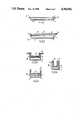
- FIG. 1is a section through a building panel
- FIG. 2is a section through a heat insulated building panel
- FIGS. 3, 4 and 5are sections through different channel components
- FIG. 6is a section through a roof panel
- FIG. 7shows the main components of the roof of FIG. 6.
- FIG. 8is a section through a fire door
- FIG. 9is s section through a typical insulation panel.
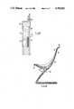
- FIG. 10is a section through a chair.
- a basic building panel 10comprises a first layer of phenolic resin impregnated glass fibre mat 11, a second layer 12 of the same material and a block of foamed phenolic resin 13 therebetween.
- the panelwas formed in a mould shaped to form a flange 14 around the panel 10, the flange being formed by adherence of the edges of the first and second layers to each other.
- the panel 10is made by placing a layer of settable phenolic resin impregnated glass fibre mat in the mould, applying a foamable mixture of phenolic resin to said first layer and covering the foamable resin with a second layer of settable phenolic resin impregnated glass fibre mat before closing the mould. Foaming of the phenolic resin starts very quickly and when more or less completed, the mould is passed into an oven to set the phenolic resin in the outer layers. The temperature of the oven may be gradually raised to about 125 degrees C. over a period of about 90 minutes. Alternatively the mould may be passed via a conveyor through a temperature graded oven over the same period of time.
- an insulated panel 20comprises the same basic structure as shown in FIG. 1 for which the same reference numerals are used for simplicity.
- the front face 11 of the panelhas a coating 21 of grit and the rear face 12 has a layer 22 of non-burning polycrystalline mullite fibre thereon and a further layer 24 of phenolic resin impregnated fibre glass.
- the grit coating 21is provided by spreading grit over the mould before the first layer of phenolic impregnated fibre glass is placed in the mould and the layer 22 is, of course, applied later. The grit adheres to the phenolic resin during the heating stage.
- FIGS. 3, 4 and 5channel section components 30, 40 and 50 are shown respectively.
- the actual componentsare basically the same as in FIG. 2 and so have been given the same numbers for convenience.
- the basic differencesare that the channel section of FIG. 3 is provided with a flange 32 whereas the others are not and the that the sections of FIGS. 3 and 4 have the insulation material of channel section whereas in FIG. 5 it is not.
- FIGS. 6 and 7concern roofing panels 60 which are substantially of the same form as the panels of FIG. 2 and so which are numbered accordingly.
- the main difference between the panels 60 and the panels 20is in the edge formations.
- the panels 20have merely flat flange edge formations
- the panels 60have a pair of shallow U-section channels 62 an opposing edge of the panel and being oppositely directed whereby the channels 62 can interfit with a suitably shaped rubber or silicone extrusion 64 therebetween to provide a continuous sealed structure.
- a fire door 78 formed in a moulding operationhas a moulded front face 80 of phenolic resin impregnated random ceramic fibre matrix having a pattern 81 formed therein during the moulding operation and a back face 85 which can be plain, embossed, textured or patterned in the same way as the front face 80.
- the hollow sections formed in the front faceare reinforced with a sprayed mix 82 or even a trowelled slurry of phenolic foam with ceramic fibre filler.
- a blanket of interlocked ceramic fibre 83is applied on eachside of a phenolic foam insert 84 between the front and back faces.
- the edges of the doorare capped with pre-moulded channel pieces 86 secured by the adhesive qualities of the phenolic resin.
- This sequence of eventsmeans that when the resin has burned away, between 30 minutes and 90 minutes depending on the construction, the bulk of the ceramic, in particular 83 still stands to act as a fire and smoke barrier. Since the ceramic can be in the form of a non woven fabric it is possible to shoulder charge through the door provided this is considered a desirable feature during the manufacturing stage.
- a moulded insulation panel 79comprises a decorative front face 87 which has been thermoformed into the female mould tool before application of a preimpregnated, sprayed trowelled or injected facing skins 88 ceramic fibre impregnated phenolic resin.
- the facing material 87must be carefully chosen to meet the desired fire and U.V. degradation specifications.
- the facing material 87may be applied to the mould as a linwer by heat, vacuum, pressure or any other suitable means.
- preimpregnated sheetshould be covered with a protective material which is a formable decorative cover in its own right which remains in place during the application, and after, of say heat and vacuum to give a finished front face.
- a protective materialwhich is a formable decorative cover in its own right which remains in place during the application, and after, of say heat and vacuum to give a finished front face.
- a suitable material for this applicationis P.V.C. in foil or thicker form.
- a layer 90 of phenolic foam impregnated with ceramic fibrethat can be injected between the skins 88 or molded separately and glued between them using the phenolic resin as an adhesive.
- the latter coursewould allow for inspection for voids and rectification procedures to be carried out on critical application.
- the edges pf the skins 88are formed into flanges with reinforcing inserts 89 therebetween of metal or other non-burning material.
- Decorative features 92can be formed during moulding and to avoid loss of protection due to thinning a mat of ceramic fibre 91 can be foamed in place between the decorative features and opposing skin 88.
- FIG. 10shows a chair 100 formed by moulding ceramic fibre filled phenolic resin to foam face mouldings 93, 94, that can be finished with plastics or paint as previously described and by joining the mouldings by adhering the phenolic flanges 98 by phenolic adhesive cured either by chemicals or heat.
- the space between faces 93, 94is filled with ceramic fibre filled phenolic foam 95 that encapsulates a metal matrix 90.
- Local strenghtening of the mouldings 97can be effected by spraying, multilaminates or trowelling.
Landscapes
- Engineering & Computer Science (AREA)
- Architecture (AREA)
- Physics & Mathematics (AREA)
- Electromagnetism (AREA)
- Civil Engineering (AREA)
- Structural Engineering (AREA)
- Laminated Bodies (AREA)
- Building Environments (AREA)
Abstract
Description
______________________________________ TO FAR 25,853 b Nil 1.0 second 74 mm TO FAR 25,853 a Nil 1.8 second 89 mm TO FAR 25,853 b-2 2 plies Zero burn rate TO FAR 25,855 a-1 2 plies Nil Nil Nil ______________________________________
______________________________________ Time of Test Specific Optical Proposed Minutes Density Limit ______________________________________ 0.5 0 50 1.0 1 50 1.5 1 50 2.0 1 50 3.0 1 50 4.0 2 50 5.0 3 50 20.0 10 50 ______________________________________
______________________________________ Level after 20 Proposed Limit Toxicant minutes ppm ppm after 4 minutes ______________________________________ Carbon monoxide 420 3500 Ammonia 1 100 Hydrogen Cyanide 8 150 Formaldehyde 3 500 Hydrogen Chloride 2 500 Nitrogen Oxides 4 100 Hydrogen Fluoride 0 50 Sulphur Dioxide 0 100 ______________________________________
Claims (13)
Applications Claiming Priority (6)
| Application Number | Priority Date | Filing Date | Title |
|---|---|---|---|
| GB8523190 | 1985-09-19 | ||
| GB858523190AGB8523190D0 (en) | 1985-09-19 | 1985-09-19 | Building panels |
| GB8531017 | 1985-12-17 | ||
| GB858531017AGB8531017D0 (en) | 1985-12-17 | 1985-12-17 | Components |
| GB868615045AGB8615045D0 (en) | 1986-06-20 | 1986-06-20 | Components |
| GB8615045 | 1986-06-20 |
Publications (1)
| Publication Number | Publication Date |
|---|---|
| US4784902Atrue US4784902A (en) | 1988-11-15 |
Family
ID=27262792
Family Applications (1)
| Application Number | Title | Priority Date | Filing Date |
|---|---|---|---|
| US06/907,880Expired - Fee RelatedUS4784902A (en) | 1985-09-19 | 1986-09-16 | Components that can exhibit low smoke, toxic fume and burning characteristics, and their manufacture |
Country Status (3)
| Country | Link |
|---|---|
| US (1) | US4784902A (en) |
| EP (1) | EP0215652A3 (en) |
| GB (1) | GB2182607B (en) |
Cited By (36)
| Publication number | Priority date | Publication date | Assignee | Title |
|---|---|---|---|---|
| US5058342A (en)* | 1987-02-11 | 1991-10-22 | Geoffrey Crompton | Moulded components and their manufacture |
| US5082494A (en)* | 1987-12-16 | 1992-01-21 | Crompton Design Manufacturing Limited | Materials for and manufacture of fire and heat resistant components |
| US5305926A (en)* | 1989-03-30 | 1994-04-26 | U-Fuel, Inc. | Portable fueling facility having fire-retardant material |
| US5556676A (en)* | 1993-01-22 | 1996-09-17 | Nisshin Chemical Industry Co. Ltd. | Tunnel interior construction |
| US5562162A (en)* | 1989-03-30 | 1996-10-08 | U-Fuel, Inc. | Portable fueling facility |
| US5657788A (en)* | 1995-08-10 | 1997-08-19 | We-Mac Manufacturing | Liquid storage container with insulated casing enclosing emergency relief vent |
| US5950872A (en)* | 1989-03-30 | 1999-09-14 | U-Fuel, Inc. | Portable fueling facility |
| US6305482B1 (en) | 1998-07-29 | 2001-10-23 | James T. Aumann | Method and apparatus for transferring core sample from core retrieval chamber under pressure for transport |
| GB2373259A (en)* | 2001-02-09 | 2002-09-18 | C A Group Ltd | Firewall |
| US20040134134A1 (en)* | 2002-10-22 | 2004-07-15 | Back Mark A. | Conservatory roof with a soffit system |
| US20040163328A1 (en)* | 2003-02-25 | 2004-08-26 | Riley John Michael | Insulated glazed roofing system |
| US20050055919A1 (en)* | 2003-08-14 | 2005-03-17 | York International Corporation | Panel construction for an air handling unit |
| US20050166479A1 (en)* | 2004-02-03 | 2005-08-04 | Park Lane Conservatories Ltd | Eaves beam with framing |
| EP1645697A1 (en)* | 2004-10-08 | 2006-04-12 | Christophe Portugues | Method and apparatus for producing construction panels, construction panels obtained thereby, method of construction using said panels and constructions obtained therewith |
| US20060244170A1 (en)* | 2003-10-24 | 2006-11-02 | Quadrant Plastic Composites Ag | Method of producing a thermoplastically moldable fiber-reinforced semifinished product |
| US20070084198A1 (en)* | 2005-10-13 | 2007-04-19 | Ohnstad Thomas S | Solid-fuel-combustion fire-insulation interface with adjacent container-wall |
| US20080034698A1 (en)* | 2006-08-10 | 2008-02-14 | Vivek Gupta | Insulating and heat dissipating panels |
| US20080241576A1 (en)* | 2004-02-02 | 2008-10-02 | Eric Le Gall | Composite Materials |
| US20090053960A1 (en)* | 2007-08-23 | 2009-02-26 | Honda Motor Co., Ltd. | Roof Liner for Vehicle and Manufacturing Method of Same |
| US7836641B2 (en) | 2002-12-16 | 2010-11-23 | Park Lane Conservatories Ltd. | Multi-piece eaves beam for preassembled glazed roof system |
| US20110016796A1 (en)* | 2009-07-27 | 2011-01-27 | Foster Mark D | Intumescent Weatherseal |
| US20140366454A1 (en)* | 2013-06-18 | 2014-12-18 | B/E Aerospace, Inc. | Aircraft galley cart bay door |
| US9458637B2 (en)* | 2012-09-25 | 2016-10-04 | Romeo Ilarian Ciuperca | Composite insulated plywood, insulated plywood concrete form and method of curing concrete using same |
| US9506307B2 (en) | 2011-03-16 | 2016-11-29 | Corpro Technologies Canada Ltd. | High pressure coring assembly and method |
| CN106233060A (en)* | 2014-07-11 | 2016-12-14 | 宝马股份公司 | Device for protecting a high-pressure gas container of a motor vehicle, a high-pressure gas container for a motor vehicle, and a method for producing a high-pressure gas container |
| US10487520B2 (en) | 2013-09-09 | 2019-11-26 | Romeo Ilarian Ciuperca | Insulated concrete slip form and method of accelerating concrete curing using same |
| CN110511531A (en)* | 2019-09-18 | 2019-11-29 | 营口象圆新材料工程技术有限公司 | A kind of phenolic foam composite board and preparation method thereof |
| JP2019211493A (en)* | 2018-05-31 | 2019-12-12 | 株式会社イノアックコーポレーション | Sound insulating material and manufacturing method of the same |
| US10639814B2 (en) | 2013-05-13 | 2020-05-05 | Romeo Ilarian Ciuperca | Insulated concrete battery mold, insulated passive concrete curing system, accelerated concrete curing apparatus and method of using same |
| US10676985B2 (en)* | 2015-02-13 | 2020-06-09 | Amesbury Group, Inc. | Low compression-force TPE weatherseals |
| US10744674B2 (en) | 2013-05-13 | 2020-08-18 | Romeo Ilarian Ciuperca | Removable composite insulated concrete form, insulated precast concrete table and method of accelerating concrete curing using same |
| CN113337074A (en)* | 2021-06-21 | 2021-09-03 | 四川炬原玄武岩纤维科技有限公司 | Basalt fiber heat-insulation integrated board and production process thereof |
| US11536040B2 (en) | 2016-01-31 | 2022-12-27 | Romeo Ilarian Ciuperca | Self-annealing concrete, self-annealing concrete forms, temperature monitoring system for self-annealing concrete forms and method of making and using same |
| US20230119745A1 (en)* | 2016-07-20 | 2023-04-20 | Jayvic Llc | Basalt Fiber Acoustic Panel |
| US20230323660A1 (en)* | 2022-04-11 | 2023-10-12 | United States Gypsum Company | Building with noncombustible exterior structural wall |
| IT202200019875A1 (en)* | 2022-09-27 | 2024-03-27 | Tecnimed Srl | FIREPROOF PROTECTIVE COATING AND PROCEDURE FOR ITS CREATION |
Families Citing this family (10)
| Publication number | Priority date | Publication date | Assignee | Title |
|---|---|---|---|---|
| US4780359A (en)* | 1987-04-03 | 1988-10-25 | Gates Formed-Fibre Products, Inc. | Fire retardent structural textile panel |
| CA2134959C (en)* | 1994-11-02 | 2002-06-11 | Vittorio De Zen | Fire rate modular building system |
| DE69521397T2 (en)* | 1994-12-22 | 2002-04-18 | Michel Georges | Fire-proof sound and heat insulation material |
| FR2728601B1 (en)* | 1994-12-22 | 1997-03-14 | Georges Michel | FIRE-RESISTANT SOUND AND THERMAL INSULATION MATERIALS |
| KR100367459B1 (en)* | 2000-01-19 | 2003-01-14 | 주식회사 한국화이바 | Phenol foam sandwich panel |
| ATE444425T1 (en) | 2007-02-16 | 2009-10-15 | Nordostschweizerische Kraftwer | LIGHTWEIGHT CONSTRUCTION ELEMENT FOR CONSTRUCTION OF WALL REINFORCEMENT OF EXISTING OBJECTS, AS WELL AS WALL REINFORCEMENT MADE OF LIGHTWEIGHT CONSTRUCTION ELEMENTS |
| FR2965883B1 (en)* | 2010-10-07 | 2013-06-14 | Faiveley Transport | FLASHING JOINT, IN PARTICULAR FOR AN OPENING OR FIXED BAY OR FRAMING OF RAILWAY OR RAIL VEHICLE BAY |
| GB2509921A (en)* | 2013-01-17 | 2014-07-23 | Jonathan Rusby | Furniture panel comprising polymeric foam sandwich |
| GB201901375D0 (en)* | 2019-01-31 | 2019-03-20 | Penso Ltd | A box van |
| EP4022247A4 (en)* | 2019-08-28 | 2023-08-23 | ATFP Associates LLC | Multi-threat mitigation security apparatus for protecting personnel, assets and critical infrastructure |
Citations (9)
| Publication number | Priority date | Publication date | Assignee | Title |
|---|---|---|---|---|
| US4118533A (en)* | 1976-01-19 | 1978-10-03 | Celotex | Structural laminate and method for making same |
| US4463043A (en)* | 1981-08-26 | 1984-07-31 | Sprinkmann Sons Corporation | Building panel |
| US4469543A (en)* | 1978-11-29 | 1984-09-04 | Allied Corporation | Lamination of highly reinforced thermoplastic composites |
| US4522876A (en)* | 1984-07-05 | 1985-06-11 | Lydall, Inc. | Integral textile composite fabric |
| US4525406A (en)* | 1983-03-15 | 1985-06-25 | Secretary of State for United Kingdom Atomic Energy Authority | Thermal insulation layer |
| US4567076A (en)* | 1984-03-23 | 1986-01-28 | The Boeing Company | Composite material structure with integrated insulating blanket and method of manufacture |
| US4596736A (en)* | 1984-06-04 | 1986-06-24 | The Dow Chemical Company | Fiber-reinforced resinous sheet |
| US4608300A (en)* | 1983-06-21 | 1986-08-26 | Ciba-Geigy Corporation | Fibre composite materials impregnated with a curable epoxide resin matrix |
| US4673614A (en)* | 1986-10-03 | 1987-06-16 | Owens-Corning Fiberglas Corporation | Roof insulation board and method of making |
Family Cites Families (13)
| Publication number | Priority date | Publication date | Assignee | Title |
|---|---|---|---|---|
| US3505161A (en)* | 1965-10-27 | 1970-04-07 | Armstrong Cork Co | Shoe upper laminate |
| DE2053910A1 (en)* | 1970-11-03 | 1972-05-10 | Felten & Guilleaume Schaltanl | Base for cable distribution cabinets |
| BE791023A (en)* | 1971-11-08 | 1973-05-07 | Dow Chemical Co | IMPROVED FOAMS BASED ON PHENOLIC RESOLS AND THEIR PREPARATION PROCESS |
| US3874980A (en)* | 1972-06-09 | 1975-04-01 | Owens Corning Fiberglass Corp | Composite foam panel with fibrous facing sheets |
| GB1411148A (en)* | 1973-02-06 | 1975-10-22 | Ici Ltd | Foam laminate |
| FR2401191A1 (en)* | 1977-03-18 | 1979-03-23 | Sicca | NEW COMPOSITE PRODUCT BASED ON POLYSTYRENE FOAM AND LIGHTENED FORMO-PHENOLIC RESIN |
| GB2032843B (en)* | 1978-10-31 | 1982-07-14 | Coal Ind | Foamed phenolic board laminate |
| DE2927122A1 (en)* | 1979-07-05 | 1981-01-08 | Roehm Gmbh | METHOD FOR THE PRODUCTION OF LAYING MATERIALS FROM HARD FOAM AND FIBER REINFORCED PLASTIC |
| US4233357A (en)* | 1979-09-06 | 1980-11-11 | Coal Industry (Patents) Limited | Laminated insulating board |
| DE3100994A1 (en)* | 1981-01-15 | 1982-08-05 | Rheinhold & Mahla Gmbh, 6800 Mannheim | Fireproof vehicle seat |
| US4361613A (en)* | 1981-09-21 | 1982-11-30 | The Quaker Oats Company | Composite construction materials with improved fire resistance |
| GB2150495B (en)* | 1983-11-25 | 1987-04-08 | Bristol Composite Mat | Structural panel |
| US4585683A (en)* | 1984-11-29 | 1986-04-29 | Bristol Composite Materials Engineering Ltd. | Structural panel |
- 1986
- 1986-09-12EPEP19860307047patent/EP0215652A3/ennot_activeCeased
- 1986-09-15GBGB8622198Apatent/GB2182607B/ennot_activeExpired - Lifetime
- 1986-09-16USUS06/907,880patent/US4784902A/ennot_activeExpired - Fee Related
Patent Citations (9)
| Publication number | Priority date | Publication date | Assignee | Title |
|---|---|---|---|---|
| US4118533A (en)* | 1976-01-19 | 1978-10-03 | Celotex | Structural laminate and method for making same |
| US4469543A (en)* | 1978-11-29 | 1984-09-04 | Allied Corporation | Lamination of highly reinforced thermoplastic composites |
| US4463043A (en)* | 1981-08-26 | 1984-07-31 | Sprinkmann Sons Corporation | Building panel |
| US4525406A (en)* | 1983-03-15 | 1985-06-25 | Secretary of State for United Kingdom Atomic Energy Authority | Thermal insulation layer |
| US4608300A (en)* | 1983-06-21 | 1986-08-26 | Ciba-Geigy Corporation | Fibre composite materials impregnated with a curable epoxide resin matrix |
| US4567076A (en)* | 1984-03-23 | 1986-01-28 | The Boeing Company | Composite material structure with integrated insulating blanket and method of manufacture |
| US4596736A (en)* | 1984-06-04 | 1986-06-24 | The Dow Chemical Company | Fiber-reinforced resinous sheet |
| US4522876A (en)* | 1984-07-05 | 1985-06-11 | Lydall, Inc. | Integral textile composite fabric |
| US4673614A (en)* | 1986-10-03 | 1987-06-16 | Owens-Corning Fiberglas Corporation | Roof insulation board and method of making |
Cited By (63)
| Publication number | Priority date | Publication date | Assignee | Title |
|---|---|---|---|---|
| US5058342A (en)* | 1987-02-11 | 1991-10-22 | Geoffrey Crompton | Moulded components and their manufacture |
| US5082494A (en)* | 1987-12-16 | 1992-01-21 | Crompton Design Manufacturing Limited | Materials for and manufacture of fire and heat resistant components |
| US6216790B1 (en) | 1989-03-30 | 2001-04-17 | U-Fuel, Inc. (Nv) | Above-ground fuel storage system |
| US5562162A (en)* | 1989-03-30 | 1996-10-08 | U-Fuel, Inc. | Portable fueling facility |
| US5950872A (en)* | 1989-03-30 | 1999-09-14 | U-Fuel, Inc. | Portable fueling facility |
| US6039123A (en)* | 1989-03-30 | 2000-03-21 | Webb; R. Michael | Above-ground fuel storage system |
| US6182710B1 (en) | 1989-03-30 | 2001-02-06 | U-Fuel, Inc. (Nv) | Method for dispensing fuel |
| US5305926A (en)* | 1989-03-30 | 1994-04-26 | U-Fuel, Inc. | Portable fueling facility having fire-retardant material |
| US5556676A (en)* | 1993-01-22 | 1996-09-17 | Nisshin Chemical Industry Co. Ltd. | Tunnel interior construction |
| US5657788A (en)* | 1995-08-10 | 1997-08-19 | We-Mac Manufacturing | Liquid storage container with insulated casing enclosing emergency relief vent |
| US6305482B1 (en) | 1998-07-29 | 2001-10-23 | James T. Aumann | Method and apparatus for transferring core sample from core retrieval chamber under pressure for transport |
| US6378631B1 (en)* | 1998-07-29 | 2002-04-30 | James T. Aumann | Apparatus for recovering core samples at in situ conditions |
| US6659204B2 (en) | 1998-07-29 | 2003-12-09 | Japan National Oil Corporation | Method and apparatus for recovering core samples under pressure |
| GB2373259A (en)* | 2001-02-09 | 2002-09-18 | C A Group Ltd | Firewall |
| GB2373259B (en)* | 2001-02-09 | 2004-04-28 | C A Group Ltd | Apparatus for constructing a firewall, and firewall incorporating such apparatus |
| US7392622B2 (en) | 2002-10-22 | 2008-07-01 | Park Lane Conservatories Limited | Conservatory roof with a soffit system |
| US20040134134A1 (en)* | 2002-10-22 | 2004-07-15 | Back Mark A. | Conservatory roof with a soffit system |
| US7836641B2 (en) | 2002-12-16 | 2010-11-23 | Park Lane Conservatories Ltd. | Multi-piece eaves beam for preassembled glazed roof system |
| US20040163328A1 (en)* | 2003-02-25 | 2004-08-26 | Riley John Michael | Insulated glazed roofing system |
| US20050055919A1 (en)* | 2003-08-14 | 2005-03-17 | York International Corporation | Panel construction for an air handling unit |
| US20100116407A1 (en)* | 2003-10-24 | 2010-05-13 | Quadrant Plastic Composites Ag | Method Of Producing A Thermoplastically Moldable Fiber-Reinforced Semifinished Product |
| US20060244170A1 (en)* | 2003-10-24 | 2006-11-02 | Quadrant Plastic Composites Ag | Method of producing a thermoplastically moldable fiber-reinforced semifinished product |
| US8540830B2 (en) | 2003-10-24 | 2013-09-24 | Quadrant Plastic Composites, AG | Method of producing a thermoplastically moldable fiber-reinforced semifinished product |
| US10688752B2 (en) | 2004-02-02 | 2020-06-23 | Zephyros, Inc. | Composite materials |
| US9186864B2 (en) | 2004-02-02 | 2015-11-17 | Zephyros, Inc. | Composite materials |
| US20080241576A1 (en)* | 2004-02-02 | 2008-10-02 | Eric Le Gall | Composite Materials |
| US11046042B2 (en) | 2004-02-02 | 2021-06-29 | Zephyros, Inc. | Composite materials |
| US8334055B2 (en) | 2004-02-02 | 2012-12-18 | Zephyros, Inc | Composite materials |
| US10035326B2 (en) | 2004-02-02 | 2018-07-31 | Zephyros, Inc. | Composite materials |
| US11618239B2 (en) | 2004-02-02 | 2023-04-04 | Zephyros, Inc. | Composite materials |
| US7392623B2 (en) | 2004-02-03 | 2008-07-01 | Park Lane Conservatories Ltd. | Eaves beam with framing |
| US20050166479A1 (en)* | 2004-02-03 | 2005-08-04 | Park Lane Conservatories Ltd | Eaves beam with framing |
| EP1645697A1 (en)* | 2004-10-08 | 2006-04-12 | Christophe Portugues | Method and apparatus for producing construction panels, construction panels obtained thereby, method of construction using said panels and constructions obtained therewith |
| US7614347B2 (en)* | 2005-10-13 | 2009-11-10 | Ohnstad Thomas S | Solid-fuel-combustion fire-insulation interface with adjacent container-wall |
| US20070084198A1 (en)* | 2005-10-13 | 2007-04-19 | Ohnstad Thomas S | Solid-fuel-combustion fire-insulation interface with adjacent container-wall |
| US8122666B2 (en)* | 2006-08-10 | 2012-02-28 | Vivek Gupta | Insulating and heat dissipating panels |
| US20080034698A1 (en)* | 2006-08-10 | 2008-02-14 | Vivek Gupta | Insulating and heat dissipating panels |
| US20090053960A1 (en)* | 2007-08-23 | 2009-02-26 | Honda Motor Co., Ltd. | Roof Liner for Vehicle and Manufacturing Method of Same |
| US8679384B2 (en) | 2009-07-27 | 2014-03-25 | Schlegel Systems Inc. | Intumescent weatherseal |
| US8510996B2 (en)* | 2009-07-27 | 2013-08-20 | Schlegel Systems Inc. | Intumescent weatherseal |
| US20110016796A1 (en)* | 2009-07-27 | 2011-01-27 | Foster Mark D | Intumescent Weatherseal |
| US9506307B2 (en) | 2011-03-16 | 2016-11-29 | Corpro Technologies Canada Ltd. | High pressure coring assembly and method |
| US9458637B2 (en)* | 2012-09-25 | 2016-10-04 | Romeo Ilarian Ciuperca | Composite insulated plywood, insulated plywood concrete form and method of curing concrete using same |
| US10744674B2 (en) | 2013-05-13 | 2020-08-18 | Romeo Ilarian Ciuperca | Removable composite insulated concrete form, insulated precast concrete table and method of accelerating concrete curing using same |
| US10639814B2 (en) | 2013-05-13 | 2020-05-05 | Romeo Ilarian Ciuperca | Insulated concrete battery mold, insulated passive concrete curing system, accelerated concrete curing apparatus and method of using same |
| US20140366454A1 (en)* | 2013-06-18 | 2014-12-18 | B/E Aerospace, Inc. | Aircraft galley cart bay door |
| CN105324053A (en)* | 2013-06-18 | 2016-02-10 | Be航天公司 | Aircraft galley cart bay door |
| US9889935B2 (en)* | 2013-06-18 | 2018-02-13 | B/E Aerospace, Inc. | Aircraft galley cart bay door |
| US10487520B2 (en) | 2013-09-09 | 2019-11-26 | Romeo Ilarian Ciuperca | Insulated concrete slip form and method of accelerating concrete curing using same |
| US10267459B2 (en)* | 2014-07-11 | 2019-04-23 | Bayerische Motoren Werke Aktiengesellschaft | Device for protecting a high-pressure gas tank in a motor vehicle, high-pressure gas tank for a motor vehicle, and method for the production of a high-pressure gas tank |
| US20170082245A1 (en)* | 2014-07-11 | 2017-03-23 | Bayerische Motoren Werke Aktiengesellschaft | Device for Protecting a High-Pressure Gas Tank in a Motor Vehicle, High-Pressure Gas Tank for a Motor Vehicle, and Method for the Production of a High-Pressure Gas Tank |
| CN106233060A (en)* | 2014-07-11 | 2016-12-14 | 宝马股份公司 | Device for protecting a high-pressure gas container of a motor vehicle, a high-pressure gas container for a motor vehicle, and a method for producing a high-pressure gas container |
| US10676985B2 (en)* | 2015-02-13 | 2020-06-09 | Amesbury Group, Inc. | Low compression-force TPE weatherseals |
| US11536040B2 (en) | 2016-01-31 | 2022-12-27 | Romeo Ilarian Ciuperca | Self-annealing concrete, self-annealing concrete forms, temperature monitoring system for self-annealing concrete forms and method of making and using same |
| US11769477B2 (en)* | 2016-07-20 | 2023-09-26 | Jayvic Llc | Basalt fiber acoustic panel |
| US20230119745A1 (en)* | 2016-07-20 | 2023-04-20 | Jayvic Llc | Basalt Fiber Acoustic Panel |
| JP2019211493A (en)* | 2018-05-31 | 2019-12-12 | 株式会社イノアックコーポレーション | Sound insulating material and manufacturing method of the same |
| JP2023025218A (en)* | 2018-05-31 | 2023-02-21 | 株式会社イノアックコーポレーション | soundproof material |
| CN110511531B (en)* | 2019-09-18 | 2022-05-17 | 营口象圆新材料工程技术有限公司 | Phenolic foam composite board and preparation method thereof |
| CN110511531A (en)* | 2019-09-18 | 2019-11-29 | 营口象圆新材料工程技术有限公司 | A kind of phenolic foam composite board and preparation method thereof |
| CN113337074A (en)* | 2021-06-21 | 2021-09-03 | 四川炬原玄武岩纤维科技有限公司 | Basalt fiber heat-insulation integrated board and production process thereof |
| US20230323660A1 (en)* | 2022-04-11 | 2023-10-12 | United States Gypsum Company | Building with noncombustible exterior structural wall |
| IT202200019875A1 (en)* | 2022-09-27 | 2024-03-27 | Tecnimed Srl | FIREPROOF PROTECTIVE COATING AND PROCEDURE FOR ITS CREATION |
Also Published As
| Publication number | Publication date |
|---|---|
| EP0215652A2 (en) | 1987-03-25 |
| GB8622198D0 (en) | 1986-10-22 |
| EP0215652A3 (en) | 1988-07-27 |
| GB2182607B (en) | 1990-05-09 |
| GB2182607A (en) | 1987-05-20 |
Similar Documents
| Publication | Publication Date | Title |
|---|---|---|
| US4784902A (en) | Components that can exhibit low smoke, toxic fume and burning characteristics, and their manufacture | |
| US20160288467A1 (en) | Moldable fire resistant composites | |
| CA1120171A (en) | Fire protective thermal barriers for foam plastics | |
| RU2085394C1 (en) | Composite material | |
| US20080070024A1 (en) | Layered fire retardant barrier panel | |
| US11965331B2 (en) | Weatherproof joint for exterior building panels | |
| JP3218359B2 (en) | Foamed refractory laminate and method of forming the same | |
| EP2423249B1 (en) | Protected expanded polyalkylidene terephthalates | |
| CN208280503U (en) | A kind of film covering type external wall thermal insulation/decoration integration board | |
| US20250187319A1 (en) | Method for producing cured polymeric skins | |
| KR20130013332A (en) | A heat insulating multipanel | |
| EP0822896B1 (en) | Laminated structure with improved fire resistance and procedure for the manufacture of the structure | |
| US20040050100A1 (en) | Method of making a foamed glass composite panel and use therefor | |
| US8962497B2 (en) | Fire resistant component | |
| KR100826958B1 (en) | Honeycomb interior material, panel with same, honeycomb interior material manufacturing method and panel manufacturing method | |
| JPH0893077A (en) | Fire-resistant covering laminate structure of steel with draining/deaerating mechanism | |
| EP2647663B1 (en) | Heat insulation panel | |
| JPH071637A (en) | Fire resistive composite plate | |
| JPH0820086A (en) | Thermal insulation panel and method of manufacturing the same | |
| RU2224855C2 (en) | Roofing unit and production method thereof | |
| CN217197244U (en) | Fireproof heat-insulation decorative plate | |
| JP2000192570A (en) | Foamed refractory sheet composition and foamed refractory sheet | |
| KR102242117B1 (en) | Quasi-noncombustible heat-insulating composite board | |
| JPH08197642A (en) | Fire-resistant panel production device | |
| RU32154U1 (en) | Decorative panel |
Legal Events
| Date | Code | Title | Description |
|---|---|---|---|
| AS | Assignment | Owner name:CROMPTON DESIGN MANUFACTURING LIMITED, 399 LORD ST Free format text:ASSIGNMENT OF ASSIGNORS INTEREST.;ASSIGNOR:CROMPTON, GEOFFREY;REEL/FRAME:005648/0437 Effective date:19881229 | |
| AS | Assignment | Owner name:CROMPTON DESIGN MANUFACTURING LIMITED, 399 LORD ST Free format text:ASSIGNMENT OF ASSIGNORS INTEREST.;ASSIGNOR:CROMPTON, GEOFFREY;REEL/FRAME:005682/0077 Effective date:19881229 | |
| FEPP | Fee payment procedure | Free format text:PAT HLDR NO LONGER CLAIMS SMALL ENT STAT AS INDIV INVENTOR (ORIGINAL EVENT CODE: LSM1); ENTITY STATUS OF PATENT OWNER: LARGE ENTITY | |
| FPAY | Fee payment | Year of fee payment:4 | |
| AS | Assignment | Owner name:BRUNNER MOND & COMPANY LIMITED, UNITED KINGDOM Free format text:ASSIGNMENT OF ASSIGNORS INTEREST;ASSIGNOR:CROMPTON DESIGN MANUFACTUIRNG LIMITED;REEL/FRAME:007709/0202 Effective date:19950720 | |
| FPAY | Fee payment | Year of fee payment:8 | |
| SULP | Surcharge for late payment | ||
| AS | Assignment | Owner name:CEEPREE PRODUCTS LIMITED, ENGLAND Free format text:ASSIGNMENT OF ASSIGNORS INTEREST;ASSIGNOR:BRUNNER MOND & COMPANY LIMITED;REEL/FRAME:008215/0110 Effective date:19960401 | |
| REMI | Maintenance fee reminder mailed | ||
| LAPS | Lapse for failure to pay maintenance fees | ||
| FP | Lapsed due to failure to pay maintenance fee | Effective date:20001115 | |
| STCH | Information on status: patent discontinuation | Free format text:PATENT EXPIRED DUE TO NONPAYMENT OF MAINTENANCE FEES UNDER 37 CFR 1.362 |