US4784763A - Water purification machine - Google Patents
Water purification machineDownload PDFInfo
- Publication number
- US4784763A US4784763AUS07/073,063US7306387AUS4784763AUS 4784763 AUS4784763 AUS 4784763AUS 7306387 AUS7306387 AUS 7306387AUS 4784763 AUS4784763 AUS 4784763A
- Authority
- US
- United States
- Prior art keywords
- water
- line
- polished
- reject
- clean water
- Prior art date
- Legal status (The legal status is an assumption and is not a legal conclusion. Google has not performed a legal analysis and makes no representation as to the accuracy of the status listed.)
- Expired - Lifetime
Links
- XLYOFNOQVPJJNP-UHFFFAOYSA-NwaterSubstancesOXLYOFNOQVPJJNP-UHFFFAOYSA-N0.000titleclaimsabstractdescription273
- 238000000746purificationMethods0.000titleclaimsdescription5
- 238000001223reverse osmosisMethods0.000claimsabstractdescription55
- 238000005498polishingMethods0.000claimsabstractdescription28
- 241000894006BacteriaSpecies0.000claimsdescription8
- 230000003134recirculating effectEffects0.000claimsdescription8
- ZAMOUSCENKQFHK-UHFFFAOYSA-NChlorine atomChemical compound[Cl]ZAMOUSCENKQFHK-UHFFFAOYSA-N0.000claimsdescription4
- 239000000460chlorineSubstances0.000claimsdescription4
- 229910052801chlorineInorganic materials0.000claimsdescription4
- 238000011109contaminationMethods0.000claimsdescription4
- 238000011010flushing procedureMethods0.000claimsdescription3
- 238000012544monitoring processMethods0.000claimsdescription3
- 230000000694effectsEffects0.000claimsdescription2
- 238000005086pumpingMethods0.000claims3
- 244000182067Fraxinus ornusSpecies0.000claims2
- 230000003213activating effectEffects0.000claims1
- 230000008878couplingEffects0.000claims1
- 238000010168coupling processMethods0.000claims1
- 238000005859coupling reactionMethods0.000claims1
- 238000010438heat treatmentMethods0.000claims1
- 239000007788liquidSubstances0.000claims1
- 239000000126substanceSubstances0.000claims1
- 150000003839saltsChemical class0.000abstractdescription9
- 239000008399tap waterSubstances0.000abstractdescription7
- 235000020679tap waterNutrition0.000abstractdescription7
- 238000000034methodMethods0.000abstractdescription6
- 230000002159abnormal effectEffects0.000abstractdescription4
- 239000012528membraneSubstances0.000description26
- 239000000047productSubstances0.000description25
- 230000000994depressogenic effectEffects0.000description11
- 239000008213purified waterSubstances0.000description10
- 230000006835compressionEffects0.000description6
- 238000007906compressionMethods0.000description6
- 239000000356contaminantSubstances0.000description6
- 238000009428plumbingMethods0.000description6
- 239000012535impuritySubstances0.000description5
- 230000009471actionEffects0.000description4
- 239000012498ultrapure waterSubstances0.000description4
- 230000004913activationEffects0.000description3
- 238000010276constructionMethods0.000description3
- 238000010586diagramMethods0.000description3
- 239000013618particulate matterSubstances0.000description3
- 230000008569processEffects0.000description3
- OKTJSMMVPCPJKN-UHFFFAOYSA-NCarbonChemical compound[C]OKTJSMMVPCPJKN-UHFFFAOYSA-N0.000description2
- 244000261422Lysimachia clethroidesSpecies0.000description2
- 230000001580bacterial effectEffects0.000description2
- 238000009434installationMethods0.000description2
- 238000005342ion exchangeMethods0.000description2
- 239000002245particleSubstances0.000description2
- 238000007789sealingMethods0.000description2
- VEUACKUBDLVUAC-UHFFFAOYSA-N[Na].[Ca]Chemical compound[Na].[Ca]VEUACKUBDLVUAC-UHFFFAOYSA-N0.000description1
- 238000013459approachMethods0.000description1
- 230000000903blocking effectEffects0.000description1
- 235000019981calcium hexametaphosphateNutrition0.000description1
- 230000015556catabolic processEffects0.000description1
- 239000003610charcoalSubstances0.000description1
- 238000006731degradation reactionMethods0.000description1
- 230000000881depressing effectEffects0.000description1
- 238000005485electric heatingMethods0.000description1
- 230000002708enhancing effectEffects0.000description1
- 230000005484gravityEffects0.000description1
- 230000002045lasting effectEffects0.000description1
- 238000002386leachingMethods0.000description1
- 239000000463materialSubstances0.000description1
- 244000005700microbiomeSpecies0.000description1
- 150000002894organic compoundsChemical class0.000description1
- 238000011045prefiltrationMethods0.000description1
- 239000012264purified productSubstances0.000description1
- 238000004064recyclingMethods0.000description1
- 230000000007visual effectEffects0.000description1
- 239000002351wastewaterSubstances0.000description1
Images


Classifications
- C—CHEMISTRY; METALLURGY
- C02—TREATMENT OF WATER, WASTE WATER, SEWAGE, OR SLUDGE
- C02F—TREATMENT OF WATER, WASTE WATER, SEWAGE, OR SLUDGE
- C02F1/00—Treatment of water, waste water, or sewage
- C02F1/44—Treatment of water, waste water, or sewage by dialysis, osmosis or reverse osmosis
- C02F1/441—Treatment of water, waste water, or sewage by dialysis, osmosis or reverse osmosis by reverse osmosis
- B—PERFORMING OPERATIONS; TRANSPORTING
- B01—PHYSICAL OR CHEMICAL PROCESSES OR APPARATUS IN GENERAL
- B01D—SEPARATION
- B01D61/00—Processes of separation using semi-permeable membranes, e.g. dialysis, osmosis or ultrafiltration; Apparatus, accessories or auxiliary operations specially adapted therefor
- B01D61/02—Reverse osmosis; Hyperfiltration ; Nanofiltration
- B01D61/08—Apparatus therefor
- B—PERFORMING OPERATIONS; TRANSPORTING
- B01—PHYSICAL OR CHEMICAL PROCESSES OR APPARATUS IN GENERAL
- B01D—SEPARATION
- B01D61/00—Processes of separation using semi-permeable membranes, e.g. dialysis, osmosis or ultrafiltration; Apparatus, accessories or auxiliary operations specially adapted therefor
- B01D61/02—Reverse osmosis; Hyperfiltration ; Nanofiltration
- B01D61/12—Controlling or regulating
- B—PERFORMING OPERATIONS; TRANSPORTING
- B01—PHYSICAL OR CHEMICAL PROCESSES OR APPARATUS IN GENERAL
- B01D—SEPARATION
- B01D65/00—Accessories or auxiliary operations, in general, for separation processes or apparatus using semi-permeable membranes
- B01D65/02—Membrane cleaning or sterilisation ; Membrane regeneration
- B—PERFORMING OPERATIONS; TRANSPORTING
- B01—PHYSICAL OR CHEMICAL PROCESSES OR APPARATUS IN GENERAL
- B01D—SEPARATION
- B01D65/00—Accessories or auxiliary operations, in general, for separation processes or apparatus using semi-permeable membranes
- B01D65/10—Testing of membranes or membrane apparatus; Detecting or repairing leaks
- B01D65/104—Detection of leaks in membrane apparatus or modules
- B—PERFORMING OPERATIONS; TRANSPORTING
- B01—PHYSICAL OR CHEMICAL PROCESSES OR APPARATUS IN GENERAL
- B01D—SEPARATION
- B01D2313/00—Details relating to membrane modules or apparatus
- B01D2313/08—Flow guidance means within the module or the apparatus
- B01D2313/083—Bypass routes
- B—PERFORMING OPERATIONS; TRANSPORTING
- B01—PHYSICAL OR CHEMICAL PROCESSES OR APPARATUS IN GENERAL
- B01D—SEPARATION
- B01D2313/00—Details relating to membrane modules or apparatus
- B01D2313/60—Specific sensors or sensor arrangements
- B—PERFORMING OPERATIONS; TRANSPORTING
- B01—PHYSICAL OR CHEMICAL PROCESSES OR APPARATUS IN GENERAL
- B01D—SEPARATION
- B01D2313/00—Details relating to membrane modules or apparatus
- B01D2313/62—Displays
- B—PERFORMING OPERATIONS; TRANSPORTING
- B01—PHYSICAL OR CHEMICAL PROCESSES OR APPARATUS IN GENERAL
- B01D—SEPARATION
- B01D2321/00—Details relating to membrane cleaning, regeneration, sterilization or to the prevention of fouling
- B01D2321/02—Forward flushing
- Y—GENERAL TAGGING OF NEW TECHNOLOGICAL DEVELOPMENTS; GENERAL TAGGING OF CROSS-SECTIONAL TECHNOLOGIES SPANNING OVER SEVERAL SECTIONS OF THE IPC; TECHNICAL SUBJECTS COVERED BY FORMER USPC CROSS-REFERENCE ART COLLECTIONS [XRACs] AND DIGESTS
- Y10—TECHNICAL SUBJECTS COVERED BY FORMER USPC
- Y10S—TECHNICAL SUBJECTS COVERED BY FORMER USPC CROSS-REFERENCE ART COLLECTIONS [XRACs] AND DIGESTS
- Y10S210/00—Liquid purification or separation
- Y10S210/90—Ultra pure water, e.g. conductivity water
Definitions
- This inventionrelates in general to the purification of water and more particularly to a method and apparatus for producing high purity, laboratory quality water.
- Purified wateris normally provided by reverse osmosis (RO) treatment which makes use of a thin membrane to produce product water that is 95% salt free.
- the reject water from the membranecontains 95% or more of the salts and is usually discarded.
- the product water from the RO cartridgeis typically stored in a storage vessel from which it is drawn when needed. Polishing cartridges which remove dissolved contaminants and colloidal particles can be used to further process the product water and provide extremely high purity type I water which is likewise stored in a tank so that it is available when needed.
- the present inventionis directed to a method and apparatus for processing ordinary tap water in order to produce laboratory quality water which may be dispensed at either of two different levels of purity (reverse osmosis product water or type I water).
- incoming tap wateris prefiltered to remove chlorine, scale and particulate contaminants, and the water is then pumped to a reverse osmosis unit which produces substantially salt free product water along with reject water which contains 95% or more of the salts.
- the clean water from the RO unitis delivered to a faucet on the cabinet of the machine, thus making RO product water available for dispensing from the faucet in a convenient manner.
- the RO product wateris also delivered to a recirculating pump which circulates it through a polishing system formed by serially arranged polishing cartridges that remove dissolved organic and inorganic contaminants and colloidal particles and microorganisms in the submicron size range.
- the polished type I water from the polishing cartridgesis delivered to a special hand held dispensing gun from which the high purity type I water can be dispensed as desired in accurately controlled amounts.
- the high purity type I wateris continuously circulated in the polishing portion of the plumbing system.
- the absence of water storage in the machineavoids problems associated with the leaching of impurities and water stagnation.
- high purity type I wateris available at all times at the dispensing gun and can be dispensed as desired.
- the dispensing gunhas a unique construction which facilitates recirculation and dispensing of the type I water.
- a pair of concentric flexible hosesconnect with the dispensing gun to supply it with incoming pure water through the inside hose while at the same time accommodating recirculation of the water away from the dispensing gun through the outer hose.
- a special tee fittingis provided to accommodate the circulation of high purity water in the polishing system while also accommodating the compact "tube within a tube” arrangement.
- the dispensing gunis equipped with a finger operated trigger which accurately controls the dispensing of high purity water.
- the triggeris spring loaded and normally pinches closed a supply tube in the dispensing gun.
- the triggercan be activated with the finger and locked in the active position to completely open the supply tube for a maximum discharge rate, as when a large container is being filled with water.
- the triggercan also be operated to only slightly release the pinching action on the supply tube, and water is then dispensed drop by drop or in other closely controlled amounts so that extremely accurate metering of the water is possible, as when a volumetric flask or other vessel is being filled to a precisely specified level.
- the machine of the present inventionalso provides a unique system for maintaining the nozzle of the dispensing gun in a sterile condition. This is accomplished by providing a heated compartment in which the nozzle is stored when the dispensing gun is not in use. The heat which is supplied to the nozzle eliminates bacteria that may be picked up, and bacteria are preventd from contaminating the water by entering through the dispenser.
- An additional feature of the inventionis the provision of an aspirated drain system that counters any tendency for bacterial contamination to occur in the drain.
- the cabinet and heater drain linesare cleared by aspiration as the RO reject water flows through the drain system, and this virtually eliminates standing water in the drain lines.
- the inventionalso provides for regular flushing of the RO membrane to periodically flush away scale and any other contaminants it may pick up, and this increases both the effectiveness and the useful life of the membrane.
- the machineis self contained and can be provided either as a free standing unit or as an undercounter unit suitable for installation beneath an existing counter. Installation is simple in that all that is required is connection to the water and drain lines of the building and electrical connection to the power that is available in the building.
- the cabinetis an attractive structure which includes a sink and drain, a magnetically attached door panel, and a special cartridge rack which provides convenient access to the cartridges for easy servicing of the filters.
- the machine of the present inventionis further characterized by a microprocessor based control system which controls all operations and constantly monitors the water quality, pressure, temperature and other conditions, all of which can be digitally displayed on the control panel. If an abnormal condition arises, the system generates an audio and visual alarm and, in the event of water leakage, the alarm is accompanied by automatic shut down of the machine.
- FIG. 1is a perspective view of a water purification machine constructed according to a preferred embodiment of the present invention, with the cartridge rack and drip pan of the machine in their extended positions and the door panel removed from the front of the machine;
- FIG. 2is a side elevational view of the machine shown in FIG. 1, with the special dispensing gun extended away from the control panel and a portion of the cabinet side broken away for purposes of illustration;
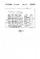
- FIG. 3is a fragmentary sectional view on an enlarged scale taken generally along line 3--3 of FIG. 2 in the direction of the arrows;
- FIG. 4is a fragmentary sectional view on an enlarged scale taken through the dispensing gun along a longitudinal plane;
- FIG. 5is a diagrammatic view of the plumbing system for the machine
- FIG. 6is a block diagram of the electrical control system of the machine.
- FIG. 7is an elevational view on an enlarged scale showing the key pad and display screens on the control panel of the machine.
- numeral 10generally designates a water purification machine constructed in accordance with the present invention.
- the machine 10functions to process ordinary tap water into high purity water suitable for use in the laboratory.
- the machine 10has a rectilinear cabinet which is generally designated by numeral 12 and which includes opposite side panels 14, a back panel 16, a floor 17 and a horizontal top 18.
- the cabinet 12rests on adjustable feet 20.
- a control panel 22projects above the top 18 near the back of the cabinet.
- An L-shaped shroud 24is bolted in place to normally cover various pumps, fittings and other components of the machine that are housed within the lower portion of cabinet 12.
- a compartment 26is provided for housing a series of filter cartridges which will be described in more detail.
- An access opening 27 in the front of the cabinetprovides ready access to compartment 26.
- a removable door panel 28normally covers the front of cabinet 12 and the access opening 27 in order to enclose the compartment 26.
- Panel 28has on its lower edge a flange 30 which is provided with a pair of openings 32 near its opposite ends. When panel 28 is in place on the cabinet, the openings 32 are fitted on pins 34 which are carried on lugs 36 projecting from the front of the cabinet. Panel 28 is held in place by a pair of magnets 38 mounted on cabinet 12 at the top of the access opening 27. Panel 28 is provided with a pair of finger pulls 40 which facilitate removal of the door panel when access to compartment 26 is required.
- the magnetically mounted door panel 28is preferred over a hinged door panel because it does not require significant room in front of the cabinet when open.
- the plumbing systemincludes an inlet line 42 which connects through a service entrance with a source of feed water such as the existing water lines of the building.
- the inlet line 42connects to an inlet pressure regulator 44 which protects the machine from excessive water pressure.
- An inlet solenoid valve 46controls the flow of feed water into the machine.
- An inlet pressure sensor line 48connects an inlet pressure transducer 50 to the inlet line.
- the inlet line 42 for the incoming tap waterleads to a filter cartridge 52 which preferably contains charcoal impregnated on a suitable filter medium.
- the filter cartridge 52removes chlorine and particulate matter from the water.
- another cartridge 54containing sodium calcium hexametaphosphate which functions as an antiscalant.
- the water leaving cartridge 54flows through line 56 to an inlet water conductivity/temperature sensor 58 which senses the electrical conductivity and temperature of the water.
- a post filter pressure line 60connects with line 56 and leads to a post filter pressure transducer 62.
- line 56Downstream from sensor 58, line 56 connects to a booster pump 64 powered by an electric motor 65.
- the booster pump 64has a discharge line 66 which connects to a reverse osmosis check valve 68.
- the reverse osmosis check valve 68is connected to the bottom of a reverse osmosis pressure vessel 70 which contains a replaceable reverse osmosis membrane (not shown).
- the reverse osmosis membranefunctions conventionally to remove 95% or more of the impurities which enter it.
- the check valve 68allows the RO cartridge to be removed without excessive spillage of water.
- the reverse osmosis purified wateris discharged from vessel 70 through a product water line 72 which is equipped with a conductivity/temperature sensor 74 for monitoring of the electrical conductivity and temperature of the purified water.
- a check valve 76 in line 72prevents reverse flow of water in the product water line 72.
- the product water line 72is connected to a recirculation tee 78 which distributes the product water for use.
- a recirculation tee 78which distributes the product water for use.
- the water which enters tee 78flows through a check valve 80 to another tee 82.
- the water which leaves tee 82flows through line 84 to the suction side of the booster pump 64.
- the check valve 80prevents reverse flow of water into the product water line 72 from tee 78.
- Tee 78has a second outlet which connects with a product water line 85 leading to a flow switch 86 and then to a distribution tee 87.
- One outlet of tee 87connects with a product water line 88 leading to a recirculation tee 89.
- the other outlet of tee 87connects through a faucet supply line 90 with a faucet valve 92 controlled by an operating handle 94.
- Valve 92controls the flow of clean water to a telescoping gooseneck faucet 96.
- faucet 96is mounted at a convenient location on the control panel 22, and the handle 94 can be operated to open valve 92 in order to dispense reverse osmosis purified water that is delivered to faucet 96.
- the reverse osmosis pressure vessel 70has a reject line 98 which delivers the reject water to a reject manifold 100.
- the pressure of the reject water (operating pressure of the reverse osmosis membrane) which enters manifold 100is monitored by a pressure transducer 102.
- Reject waterthen flows to a tee 104 which directs the water either to a back-pressure regulator 106 along one path or a solenoid flush valve 108 along another path.
- the backpressure regulator 106maintains a constant backpressure on the reverse osmosis membrane.
- the normally closed solenoid flush valve 108allows the water to bypass the regulator 106, resulting in a low pressure flush of the membrane.
- the reject wateris directed through valve 108 to a flush tee 110 and on through tee 110 to a reject drain tee 112.
- a reject recirculation tee 113Connected to the downstream side of regulator 106 is a reject recirculation tee 113 which directs the reject water either to a reject control solenoid valve 114 or through an adjustment valve 115 to a check valve 116, depending upon whether or not valve 114 is open.
- the check valve 116connects with tee 110.
- the reject control solenoid valve 114opens, directing a large volume of reject water through tee 112 and an aspirator 118 to a drain 120 for the building.
- a drain line 121connects the aspirator 118 to the drain 120.
- the reject control valve 114is closed, and the reject water is then directed largely from tee 113 through tee 110 to a recirculation line 122 which leads to the reject recirculation tee 82.
- the recirculating reject waterthen flows through line 84 to the booster pump 64.
- the recirculation check valve 116prevents the flow of water in the reverse direction.
- a small fraction of the reject wateris removed and sent to the drain via the reject water adjustment valve 115.
- the polishing system which produces deionized Type I waterincludes the recirculation tee 89 which delivers the water to a recirculation pump 142.
- the discharge side of the recirculation pumpconnects with a discharge line 144 that leads to four serially arranged polishing cartridges 146, 148, 150, and 152 forming the polishing system of the machine.
- the first cartridge 146contains activated carbon and removes dissolved organic compounds.
- the second and third cartridges 148 and 150are ion exchange cartridges which remove ionic contaminants by ion exchange.
- the final cartridge 152may be a submicron filter which removes particulate matter larger than 0.2 microns.
- cartridge 152may be an ultrafilter cartridge, with a molecular weight cutoff of 10,000 Daltons.
- the polishing cartridgesproduce Type I water which flows through line 156 to a special tee fitting 158.
- a polished water resistivity/temperature sensor 159 located at the top of cartridge 150senses the electrical resistance and temperature of the polished water.
- the polished water delivered to fitting 158is supplied to a specially constructed dispensing gun 160 and is circulated from the dispensing gun back to fitting 158 and then away from the fitting along a recirculation line 161.
- a check valve 162prevents reverse flow of water in the recirculation line 161.
- the recirculation line 161connects to the recirculation tee 89 which is in turn connected with the suction side of pump 142.
- the configuration of the special tee fitting 158is best shown in FIG. 3.
- the fittingincludes a T-shaped body 164 to which line 156 is attached through a connector 166 which is threaded onto the lower end of body 164.
- a nut 168is threaded onto the lower end of connector 166 and compresses an O-ring 170 which seals line 156 to the connector.
- the connector 166retains a flanged tube support 172 in the end of a flexible supply hose 174 which extends through body 164 and also through a flexible outer hose 176.
- Hose 176is larger in diameter than the supply hose 174 and is sleeved around the supply hose in order to form an annular flow passage 178 between hoses 174 and 176. Passage 178 accommodates water which is returned from the dispensing gun, as will be explained in more detail.
- the outer hose 176is secured to the top of body 164 by a barbed fitting 180 on the inside and a nut 182 threaded onto body 164 outside of hose 176.
- Fitting 180is somewhat larger than hose 174 in order to provide a flow passage 184 which connects passage 178 with a flow chamber 186 formed within body 164.
- the flow chamber 186is isolated from the inside of the supply hose 174 and connects with the recirculation line 161 in order to deliver the recirculating water thereto.
- a nut 188is threaded onto body 164 to compress an O-ring 190 which provides a seal between body 164 and the recirculation line 161.
- the gun 160is a hand held dispenser and includes a generally cylindrical body 194 having a size and shape to be conveniently held in the hand.
- the supply hose 174extends into the lower end of the body 194 and receives in its end a flanged tube support 196 held by a fitting 198 which is in turn secured by an end cap 200.
- An O-ring 202seals fitting 198 to the outer hose 176.
- the supply hose 174connects with a compressible supply tube 204 which is held in place at the bottom by a flanged tube support 206 and at the top by another flanged tube support 208.
- Tube support 206is sealed to tube support 196 by a sealing ring 210.
- Tube 204extends into the head 212 of the dispensing gun and has in its end the flanged tube support 210 which is sealed to a nozzle 214 by a sealing ring 216.
- the head 212is secured to the body 194 by a screw 218.
- Nozzle 214terminates in a dispensing tip through which the polished water is dispensed. The nozzle may be threaded onto the head 212 or secured in any other suitable manner.
- the supply tube 204is controlled by a finger operated trigger 220 which is mounted on the dispenser body 194.
- a pivot pin 222mounts the trigger 220 on the dispenser body 194, and a compression spring 224 continuously urges trigger 220 to pivot about pin 222 toward the closed position of the dispenser shown in FIG. 4. In this position, a tip 226 of the trigger 220 pinches the supply tube 204 closed, thus completely blocking the flow of water to the nozzle 214.
- Trigger 220can be opened to any desired extent in order to dispense water at various rates between the fully opened and fully closed condition.
- a pivot pin 228mounts a trigger latch 230 in the trigger 220.
- a compression spring 232continuously urges the latch to remain in the retracted position, as shown in FIG. 4.
- the construction and arrangement of the supply tube 204 and trigger 220 and the pinching action provided by the triggerpermits accurate metering of the rate at which water is dispensed from the dispensing gun 160.
- the supply tube 204can be only slightly opened such that water is able to pass through the supply tube one drop at a time, and the water is then dispensed through nozzle 214 drop by drop, as when a volumetric flask is being filled to a specified level.
- the latching action of the trigger provided by latch 220allows large volumes of water to be dispensed, as when large storage tanks are being filled, without requiring that continuous pressure be maintained on the trigger.
- the supply hose 174is provided with a plurality of openings 238 at a location adjacent the dispensing gun 160. Openings 238 provide passages through which the polished water can flow from tube 174 into the annular flow passage 178 which leads to the special tee fitting 158 and to the recirculation line 161.
- a boss 240 formed on the control panel 22is provided with a pocket or compartment 242 (see FIG. 2) having a size and shape to closely receive the nozzle 214 of the dispensing gun.
- the fit of the nozzle in compartment 242maintains the dispensing gun in its storage position on the machine.
- An electric heating element 244is coiled around compartment 242 and heats the compartment to a temperature of approximately 90° C. The heat is supplied to nozzle 214 and is sufficient to eliminate any bacteria that may be picked up on the tip of the dispensing gun. In this manner, the dispensing gun nozzle is maintained in a sterile condition, and bccteria are prevented from contaminating the polished water through the dispensing gun.
- hose 176(and the smaller hose 174 contained therein) extends within compartment 26 of the cabinet and connects with the dispensing gun 160 through a passage formed in the top panel 18 of the cabinet.
- hose 176is looped at 176a, and a weight 245 is hung on the loop 176a.
- the weight 245urges the dispensing gun 160 to retract toward the cabinet.
- Hose 176then extends through the opening in panel 18 against the force applied by the weight 245.
- weight 245acts to retract hose 176 within compartment 26.
- the filter and polishing cartridgesare held on a special rack 246 which is best shown in FIGS. 1 and 2.
- the rack 246includes opposite sides 247 and a pair of horizontal plates 248 and 249 which extend between the sides 247.
- Each side 247is provided with a wheel 248a (see FIG. 2) which rides in a track 249a mounted on the inside surface of the cabinet side panel 14.
- the side panels 14are provided with wheels 250 which roll in tracks 251 on the opposite sides 247 of the rack.
- the wheels and tracksallow rack 246 to be fully retracted into compartment 26 when the machine is in operation, and they also permit the rack 246 to be extended out of the compartment for easy access to and servicing of the filter and polishing cartridges.
- the cartridgesare carried on rack 246 in two rows.
- the front rowincludes three of the cartridges (such as cartridges 52, 54 and 152) carried on the front plate 248.
- the back rowincludes the other three cartridges (146, 148 and 150) which are carried on the back plate 249.
- Each cartridgeincludes a cap 252 into which a cartridge body 253 is threaded.
- the filter material or other functional part of each cartridgeis contained within the cartridge body 253, while each cap 252 is secured to the underside of one of the plates 248 or 249.
- rack 246facilitates changing of the filters and other servicing of the cartridges.
- the three cartridges in the front roware easily accessible, and each cartridge body 253 can be turned in order to unthread it from and thread it into its cap 252.
- the cartridges in the back roware not as accessible, but they can be reached without great difficulty when the rack 246 is extended to the position shown in FIG. 1.
- the back plate 249is raised relative to the front plate 248, and a space 254 is thereby provided through which the threaded connections between caps 252 and the cartridge bodies 253 in the back row can be viewed. Consequently, the serviceman changing the filters is able to view the caps in the back row and can easily thread the cartridge bodies into them since he does not have to rely entirely on "feel" in order to start the threading of the cartridge bodies.
- a sliding drip pan 255is located at the bottom of compartment 26.
- Pan 255is supported on a pair of slides 256 (see FIG. 1) which are part of shroud 24. Consequently, pan 255 can be extended beneath rack 246 when the rack is extended, and the drip pan then underlies the cartridges carried on the rack in order to catch any water that may spill when the cartridges are being changed or otherwise serviced.
- Pan 255can be removed to pour out any water that it catches, and it can be slid back into compartment 26 when rack 246 is retracted into the cabinet.
- the upper surface of the cabinet top 18is provided with a drain opening 257 and with grooves 257a which direct spilled water to the drain opening. Opening 257 and grooves 257a are located adjacent to the control panel 22 where they are best able to catch any water that spills from the faucet 96 or the dispensing gun 160.
- the drain opening 257 and compartment 242connect with respective drain lines 258 and 259 which lead to a tee 260. Extending from the tee 260 is a drain line 261 equipped with a filter 262 and a check valve 263. Line 261 leads to the aspirator 118.
- waste water from the drain opening 257 and compartment 242is removed by the vacuum created by the aspirator 118 from tee 112 through the aspirator and drain line 121.
- the control panel 22 of the machineis provided with a key pad and a display which are best shown in FIG. 7.
- a main screen 264provides a digital display of the various conditions that are monitored by the control system.
- the water quality of the type I watermay be displayed on a megohm-cm display screen 265 which is preferably a bar type display.
- the key padincludes a power key 266 having an associated LED 266a which is energized when the power key is depressed to provide operating power to the machine.
- a flush key 267may be depressed to open the normally closed flush solenoid valve 108, and LED 267a is activated whenever the flush solenoid is energized either by depression of key 267 or by automatic flushing of the RO membrane, as will be described more fully.
- a leak reset key 268may be depressed to reset the leak system after it has detected a leak and deactivated the machine.
- the leak systemincludes a pair of spaced apart electrical contacts 269 located on the floor 17 of the cabinet (See FIG. 2). If water leaks onto the floor, there is electrical continuity between the contacts 269, and this deactivates the machine. The machine can be reset only when the leak condition has been corrected.
- the leak reset key 268has an associated LED 268a.
- the key padfurther includes an inlet conductivity key 270 which may be activated to provide a digital display on screen 264 of the conductivity of the inlet water (displayed in micro siemens).
- Key 270has an associated LED 270a.
- An R/O conductivity key 272may be activated to provide a digital display of the conductivity of the water produced by the membrane of the RO cartridge 70.
- An LED 272ais energized when the R/O conductivity is being displayed.
- a percent reject key 274may be activated to provide a display of the percent of the salts that the RO membrane is rejecting (based on electrical conductivity).
- An associated LED 274ais energized when the percent reject key is active.
- Temperature display keys 276, 278 and 280are provided on the key pad. Each has an associated LED 276a, 278a or 280a which is energized when the corresponding key is active. When key 276 is active, a digital display is provided indicating the temperature of the incoming water as sensed by the inlet temperature sensor 58. Key 278 provides a digital display of the temperature of the clean water produced by the RO membrane, as sensed by sensor 74. Activation of key 280 provides a digital display of the temperature of the polished water, as sensed by sensor 159.
- the key padalso includes pressure keys 282, 284 and 286 and associated LEDs 282a, 284a and 286a.
- screen 264provides a digital display of the pressure of the incoming water, as sensed by the pressure transducer 50.
- Activation of key 284provides a digital display of the pressure sensed by pressure transducer 102.
- Key 286provides a digital display of the pressure drop from the inlet pressure transducer 50 and the post-filter pressure transducer 62.
- Key 288permits selection to be made between a display on screen 265 of the polished water quality (in megohms-cm), as detected by sensor 159, and the water quality alarm set point, which may be set by key 290.
- LEDs 288a and 290aare energized.
- Key 290can be used to select any water quality alarm point between 1 and 18 megohms-cm.
- Key 292is used to activate and deactivate the audible alarm.
- An LED 292ais energized when the alarm is active and is deenergized when the alarm is inactive.
- the machineincludes a microprocessor based electrical control system which is illustrated in block diagram form in FIG. 6.
- a microprocessor 294controls the operation of the machine and generates the displays on screens 264 and 265 under the control of the keys on the key pad. For example, when the inlet conductivity key 270 is activated, the microprocessor 294 causes the screen 264 to provide a digital display of the conductivity of the inlet water as sensed by the inlet conductivity sensor 50.
- a percent reject block 296calculates the percent of salts that are rejected by the membrane of the RO unit 70.
- This calculationis made by subtracting the conductivity of the reverse osmosis product water from the conductivity of the inlet water and dividing the difference by the conductivity of the inlet water (and then converting to percentage). Normally, 95% or more of the salts are rejected by the RO unit 70. However, if the rejection percentage falls below a preselected level (such as 80%, for example), an audible alarm 298 is automatically activated to generate an audible alarm signal, and LED 274a is caused to flash. Thus, both audible and visible alarms are generated if the percent of salt rejection in the reverse osmosis membrane is abnormally low, thus indicating that corrective action should be taken.
- a preselected levelsuch as 80%, for example
- keys 276, 278, 280, 282, 284, and 286can be activated to provide on screen 264 a digital display of the temperatures and pressures in various parts of the plumbing system. If the inlet temperature sensed by sensor 58 is excessive (such as above 35° C., for example), LED 276a is caused to flash and the alarm 298 is activated. In addition, the machine is automatically shut down by block 300. If the temperature sensed by sensor 24 exceeds a predetermined level (such as 40° C.), LED 278a flashes, the alarm 298 is activated, and block 300 shuts down the machine. In this manner, excessive water temperatures are avoided and both audible andvisual alarm signals are given to indicate the existence of, abnormal temperature conditions. The temperature keys 276 and 278 can be depressed to reset the machine into normal operation once the abnormal temperature condition has been corrected.
- a timing circuit 304is arranged in parallel with the manual flush key 267 such that the flush solenoid valve 108 is opened whenever key 267 is depressed and also whenever the timer 304 causes automatic opening of valve 108.
- the timer 304is set to cause the occurrence of a four minute flush cycle every two hours. If the machine is inactive (power off) when the automatic flush occurs, the inlet solenoid valve 44 and both pumps 64 and 142 are activated along with valve 108 for the duration of the flush cycle.
- the machineWhen a leak is detected by contacts 269, the machine is immediately shut down via blocks 306 and 300. If the condition causing the leak has been corrected, the leak reset key 268 can be activated to reset the leak system 306 through reset block 308.
- the selector switch 288can be set in the position shown in FIG. 6 to cause the megohm display 265 to visually indicate the quality of the type I polished water in megohms-cm.
- Switch 288can be depressed again to cause the megohm-cm display 265 to display an alarm setting which is the (arbitrarily selected) minimum water quality that is acceptable.
- Switch 290can be activated to set the water quality alarm set point at any selected value between 1 and 18 megohms-cm.
- Switch 292can be depressed to activate or deactivate the audible alarm. If the alarm is activated and the water quality drops below the set level, LED 290a is caused to flash and an audible alarm signal is generated to indicate both visually and audibly that the water quality is unduly low.
- ordinary tap water from the water line of the buildingis supplied to the inlet line 42 and is directed through the prefilters 52 and 54 which remove chlorine, particulate matter and add an antiscalant.
- the filtered wateris then delivered to the booster pump 64 which increases the pressure of the water flowing through line 66 to the RO cartridge 70.
- the RO membraneremoves 95% or more of the impurities contained in the tap water and discharges the purified product water through line 72.
- the reject wateris discharged through line 98.
- the product waterflows through fitting 78 and along line 85 to the flow switch 86.
- the product wateris then delivered to tee 87 where it is made available to the gooseneck faucet 96 on the control panel 22 of the machine. By operating the handle 94, the product water can be dispensed as desired from the faucet 96.
- the reject water which the RO unit 70 discharges through line 98is delivered to the reject manifold 100 and normally flows through the pressure sensor 102, fitting 104, the pressure reulator 106, fitting 113, valve 114, tee 112, aspirator 118 and to the service drain of the building via line 121.
- the machineWhen there is no demand for purified water, the machine reverts to a standby mode of operation in which most of the reject water is recycled.
- the flow pattern in the standby modeis through pressure sensor 102, fitting 104, pressure regulator 106, fitting 113, check valve 116, recirculation line 122 and through the recirculation tee 82 to the booster pump 64 via line 84.
- a small part of the reject wateris diverted from the recirculation path by valve 115 and delivered through tees 110 and 112 to the aspirator 118 and then to the service drain via line 121.
- the flush valve 108Whenever the flush valve 108 is open, the reject water which reaches the reject manifold 100 is able to flow to the drain through fitting 102, valve 108, tee 110, tee 112, aspirator 118 and line 121.
- This flush pathbypasses the backpressure regulator 106, and the water is able to flow through the reverse ososis membrane at a reduced pressure and, thus, an increased velocity.
- the increased velocity of water across the surface of the membranecleans the membrane by removing scale, bacteria and other deposits from it.
- the flush valve 108is opened automatically at regular intervals in order to periodically flush the RO membrane.
- key 267can be manually depressed at any time the machine is activated in order to effect a flush cycle lasting a preselected time (such as four minutes, for example). At the end of each flush cycle, valve 108 closes and the normal path to the drain is reestablished.
- the reverse osmosis product water which is supplied to faucet 96is also made available to the polishing system.
- the product waterpasses from tee 87 through line 88 and tee 89 to the intake 140 of pump 142.
- the wateris discharged from pump 142 through line 144 and is pumped serially through polishing cartridges 146, 148, 150 and 152.
- the polished water produced by the polishing systemflows along line 156 to the special tee fitting 158 and is made available to the dispensing gun 160 through the inner hose 174.
- the water that is not dispensed from the dispensing gun 160flows through openings 238, into passage 178 and back through fitting 158 to the recirculation line 161.
- the recirculating wateris directed through check valve 162 and tee 89 back to the intake of pump 142 which again pumps it through the polishing system.
- polished high purity type I wateris immediately available at all times to the dispensing gun 160.
- the type I wateris continuously recirculated through the polishing system and does not remain stationary such that it could be subject to stagnation and other problems associated with the storage of high purity water in a tank.
- the reverse osmosis product wateris recycled to pump 64 and is thus kept constantly in motion to avoid stagnation and related problems.
Landscapes
- Chemical & Material Sciences (AREA)
- Engineering & Computer Science (AREA)
- Water Supply & Treatment (AREA)
- Chemical Kinetics & Catalysis (AREA)
- Nanotechnology (AREA)
- Life Sciences & Earth Sciences (AREA)
- Hydrology & Water Resources (AREA)
- Environmental & Geological Engineering (AREA)
- Organic Chemistry (AREA)
- Separation Using Semi-Permeable Membranes (AREA)
Abstract
Description
This invention relates in general to the purification of water and more particularly to a method and apparatus for producing high purity, laboratory quality water.
In laboratory work, water having various levels of purity is required for different laboratory projects. The highest quality water is referred to as "type I" water by several professional organizations and approaches the theoretical maximum level of purity (approximately 18 megohms). Unless water having this extremely high level of purity is needed, less pure water is used.
Purified water is normally provided by reverse osmosis (RO) treatment which makes use of a thin membrane to produce product water that is 95% salt free. The reject water from the membrane contains 95% or more of the salts and is usually discarded. The product water from the RO cartridge is typically stored in a storage vessel from which it is drawn when needed. Polishing cartridges which remove dissolved contaminants and colloidal particles can be used to further process the product water and provide extremely high purity type I water which is likewise stored in a tank so that it is available when needed.
The storage of purified water and particularly type I water is undesirable because contaminants from the storage vessel tend to leach into the water and degrade its purity. In addition, stagnant water in the storage vessel is subject to bacteria contamination which causes further degradation of the purity. Stagnant water in drains and other parts of the plumbing system can cause similar problems. Another problem is that the RO membrane tends to become clogged with inorganic scale and bacteria which reduce its effectiveness and useful life. The membranes are high cost items, and the need to frequently replace them adds appreciably to the cost of producing high quality water.
The present invention is directed to a method and apparatus for processing ordinary tap water in order to produce laboratory quality water which may be dispensed at either of two different levels of purity (reverse osmosis product water or type I water). In accordance with the invention, incoming tap water is prefiltered to remove chlorine, scale and particulate contaminants, and the water is then pumped to a reverse osmosis unit which produces substantially salt free product water along with reject water which contains 95% or more of the salts. The clean water from the RO unit is delivered to a faucet on the cabinet of the machine, thus making RO product water available for dispensing from the faucet in a convenient manner.
The RO product water is also delivered to a recirculating pump which circulates it through a polishing system formed by serially arranged polishing cartridges that remove dissolved organic and inorganic contaminants and colloidal particles and microorganisms in the submicron size range. The polished type I water from the polishing cartridges is delivered to a special hand held dispensing gun from which the high purity type I water can be dispensed as desired in accurately controlled amounts.
It is a particularly important feature of the invention that the high purity type I water is continuously circulated in the polishing portion of the plumbing system. The absence of water storage in the machine avoids problems associated with the leaching of impurities and water stagnation. At the same time, high purity type I water is available at all times at the dispensing gun and can be dispensed as desired.
The dispensing gun has a unique construction which facilitates recirculation and dispensing of the type I water. A pair of concentric flexible hoses connect with the dispensing gun to supply it with incoming pure water through the inside hose while at the same time accommodating recirculation of the water away from the dispensing gun through the outer hose. A special tee fitting is provided to accommodate the circulation of high purity water in the polishing system while also accommodating the compact "tube within a tube" arrangement.
The dispensing gun is equipped with a finger operated trigger which accurately controls the dispensing of high purity water. The trigger is spring loaded and normally pinches closed a supply tube in the dispensing gun. The trigger can be activated with the finger and locked in the active position to completely open the supply tube for a maximum discharge rate, as when a large container is being filled with water. The trigger can also be operated to only slightly release the pinching action on the supply tube, and water is then dispensed drop by drop or in other closely controlled amounts so that extremely accurate metering of the water is possible, as when a volumetric flask or other vessel is being filled to a precisely specified level.
The machine of the present invention also provides a unique system for maintaining the nozzle of the dispensing gun in a sterile condition. This is accomplished by providing a heated compartment in which the nozzle is stored when the dispensing gun is not in use. The heat which is supplied to the nozzle eliminates bacteria that may be picked up, and bacteria are preventd from contaminating the water by entering through the dispenser.
An additional feature of the invention is the provision of an aspirated drain system that counters any tendency for bacterial contamination to occur in the drain. The cabinet and heater drain lines are cleared by aspiration as the RO reject water flows through the drain system, and this virtually eliminates standing water in the drain lines.
Among the other features of the invention are the reuse of part of the reject water from the RO membrane in order to conserve water and the recycling of the clean product water from the membrane in order to enhance the purity of the water which is delivered to the membrane and prevent standing water in the system. The invention also provides for regular flushing of the RO membrane to periodically flush away scale and any other contaminants it may pick up, and this increases both the effectiveness and the useful life of the membrane.
The machine is self contained and can be provided either as a free standing unit or as an undercounter unit suitable for installation beneath an existing counter. Installation is simple in that all that is required is connection to the water and drain lines of the building and electrical connection to the power that is available in the building. The cabinet is an attractive structure which includes a sink and drain, a magnetically attached door panel, and a special cartridge rack which provides convenient access to the cartridges for easy servicing of the filters.
The machine of the present invention is further characterized by a microprocessor based control system which controls all operations and constantly monitors the water quality, pressure, temperature and other conditions, all of which can be digitally displayed on the control panel. If an abnormal condition arises, the system generates an audio and visual alarm and, in the event of water leakage, the alarm is accompanied by automatic shut down of the machine.
In the accompanying drawings which form a part of the specification and are to be read in conjunction therewith and in which like reference numerals are used to indicate like parts in the various views:
FIG. 1 is a perspective view of a water purification machine constructed according to a preferred embodiment of the present invention, with the cartridge rack and drip pan of the machine in their extended positions and the door panel removed from the front of the machine;
FIG. 2 is a side elevational view of the machine shown in FIG. 1, with the special dispensing gun extended away from the control panel and a portion of the cabinet side broken away for purposes of illustration;
FIG. 3 is a fragmentary sectional view on an enlarged scale taken generally alongline 3--3 of FIG. 2 in the direction of the arrows;
FIG. 4 is a fragmentary sectional view on an enlarged scale taken through the dispensing gun along a longitudinal plane;
FIG. 5 is a diagrammatic view of the plumbing system for the machine;
FIG. 6 is a block diagram of the electrical control system of the machine; and
FIG. 7 is an elevational view on an enlarged scale showing the key pad and display screens on the control panel of the machine.
Referring now to the drawings in more detail and initially to FIGS. 1 and 2,numeral 10 generally designates a water purification machine constructed in accordance with the present invention. Themachine 10 functions to process ordinary tap water into high purity water suitable for use in the laboratory. Themachine 10 has a rectilinear cabinet which is generally designated bynumeral 12 and which includesopposite side panels 14, aback panel 16, afloor 17 and ahorizontal top 18. Thecabinet 12 rests onadjustable feet 20. Acontrol panel 22 projects above thetop 18 near the back of the cabinet. An L-shaped shroud 24 is bolted in place to normally cover various pumps, fittings and other components of the machine that are housed within the lower portion ofcabinet 12. Above theshroud 24, acompartment 26 is provided for housing a series of filter cartridges which will be described in more detail. An access opening 27 in the front of the cabinet provides ready access tocompartment 26.
Aremovable door panel 28 normally covers the front ofcabinet 12 and the access opening 27 in order to enclose thecompartment 26.Panel 28 has on its lower edge aflange 30 which is provided with a pair ofopenings 32 near its opposite ends. Whenpanel 28 is in place on the cabinet, theopenings 32 are fitted onpins 34 which are carried onlugs 36 projecting from the front of the cabinet.Panel 28 is held in place by a pair ofmagnets 38 mounted oncabinet 12 at the top of the access opening 27.Panel 28 is provided with a pair offinger pulls 40 which facilitate removal of the door panel when access tocompartment 26 is required. The magnetically mounteddoor panel 28 is preferred over a hinged door panel because it does not require significant room in front of the cabinet when open.
The process by which water is purified by themachine 10 is best illustrated in the plumbing diagram of FIG. 5. The plumbing system includes an inlet line 42 which connects through a service entrance with a source of feed water such as the existing water lines of the building. The inlet line 42 connects to aninlet pressure regulator 44 which protects the machine from excessive water pressure. Aninlet solenoid valve 46 controls the flow of feed water into the machine. An inletpressure sensor line 48 connects an inlet pressure transducer 50 to the inlet line.
The inlet line 42 for the incoming tap water leads to afilter cartridge 52 which preferably contains charcoal impregnated on a suitable filter medium. Thefilter cartridge 52 removes chlorine and particulate matter from the water. Arranged in series withfilter 52 is anothercartridge 54 containing sodium calcium hexametaphosphate which functions as an antiscalant. Thewater leaving cartridge 54 flows throughline 56 to an inlet water conductivity/temperature sensor 58 which senses the electrical conductivity and temperature of the water. A postfilter pressure line 60 connects withline 56 and leads to a postfilter pressure transducer 62.
Downstream fromsensor 58,line 56 connects to abooster pump 64 powered by anelectric motor 65. Thebooster pump 64 has adischarge line 66 which connects to a reverseosmosis check valve 68. The reverseosmosis check valve 68 is connected to the bottom of a reverseosmosis pressure vessel 70 which contains a replaceable reverse osmosis membrane (not shown). The reverse osmosis membrane functions conventionally to remove 95% or more of the impurities which enter it. Thecheck valve 68 allows the RO cartridge to be removed without excessive spillage of water.
The reverse osmosis purified water is discharged fromvessel 70 through aproduct water line 72 which is equipped with a conductivity/temperature sensor 74 for monitoring of the electrical conductivity and temperature of the purified water. Acheck valve 76 inline 72 prevents reverse flow of water in theproduct water line 72.
Theproduct water line 72 is connected to arecirculation tee 78 which distributes the product water for use. When there is no demand for purified water, the water which enterstee 78 flows through acheck valve 80 to another tee 82. The water which leaves tee 82 flows throughline 84 to the suction side of thebooster pump 64. Thecheck valve 80 prevents reverse flow of water into theproduct water line 72 fromtee 78.
The reverseosmosis pressure vessel 70 has areject line 98 which delivers the reject water to areject manifold 100. The pressure of the reject water (operating pressure of the reverse osmosis membrane) which entersmanifold 100 is monitored by apressure transducer 102. Reject water then flows to atee 104 which directs the water either to a back-pressure regulator 106 along one path or a solenoid flush valve 108 along another path. Thebackpressure regulator 106 maintains a constant backpressure on the reverse osmosis membrane. When energized, the normally closed solenoid flush valve 108 allows the water to bypass theregulator 106, resulting in a low pressure flush of the membrane. During a flush, the reject water is directed through valve 108 to aflush tee 110 and on throughtee 110 to a reject drain tee 112. Connected to the downstream side ofregulator 106 is areject recirculation tee 113 which directs the reject water either to a rejectcontrol solenoid valve 114 or through anadjustment valve 115 to acheck valve 116, depending upon whether or notvalve 114 is open. Thecheck valve 116 connects withtee 110.
During periods of purified water demand, the rejectcontrol solenoid valve 114 opens, directing a large volume of reject water through tee 112 and anaspirator 118 to adrain 120 for the building. A drain line 121 connects theaspirator 118 to thedrain 120. When there is no purified water demand, thereject control valve 114 is closed, and the reject water is then directed largely fromtee 113 throughtee 110 to arecirculation line 122 which leads to the reject recirculation tee 82. The recirculating reject water then flows throughline 84 to thebooster pump 64. Therecirculation check valve 116 prevents the flow of water in the reverse direction. During periods of no product water demand, a small fraction of the reject water is removed and sent to the drain via the rejectwater adjustment valve 115.
The polishing system which produces deionized Type I water includes therecirculation tee 89 which delivers the water to arecirculation pump 142. The discharge side of the recirculation pump connects with adischarge line 144 that leads to four serially arranged polishingcartridges first cartridge 146 contains activated carbon and removes dissolved organic compounds. The second andthird cartridges 148 and 150 are ion exchange cartridges which remove ionic contaminants by ion exchange. Thefinal cartridge 152 may be a submicron filter which removes particulate matter larger than 0.2 microns. Alternatively,cartridge 152 may be an ultrafilter cartridge, with a molecular weight cutoff of 10,000 Daltons. The polishing cartridges produce Type I water which flows throughline 156 to aspecial tee fitting 158. A polished water resistivity/temperature sensor 159 located at the top of cartridge 150 senses the electrical resistance and temperature of the polished water.
As will be explained in more detail, the polished water delivered to fitting 158 is supplied to a specially constructed dispensinggun 160 and is circulated from the dispensing gun back to fitting 158 and then away from the fitting along arecirculation line 161. Acheck valve 162 prevents reverse flow of water in therecirculation line 161. Therecirculation line 161 connects to therecirculation tee 89 which is in turn connected with the suction side ofpump 142. The configuration of the special tee fitting 158 is best shown in FIG. 3. The fitting includes a T-shapedbody 164 to whichline 156 is attached through aconnector 166 which is threaded onto the lower end ofbody 164. Anut 168 is threaded onto the lower end ofconnector 166 and compresses an O-ring 170 which sealsline 156 to the connector. Theconnector 166 retains aflanged tube support 172 in the end of aflexible supply hose 174 which extends throughbody 164 and also through a flexibleouter hose 176.Hose 176 is larger in diameter than thesupply hose 174 and is sleeved around the supply hose in order to form anannular flow passage 178 betweenhoses Passage 178 accommodates water which is returned from the dispensing gun, as will be explained in more detail.
Theouter hose 176 is secured to the top ofbody 164 by a barbed fitting 180 on the inside and anut 182 threaded ontobody 164 outside ofhose 176. Fitting 180 is somewhat larger thanhose 174 in order to provide aflow passage 184 which connectspassage 178 with aflow chamber 186 formed withinbody 164. Theflow chamber 186 is isolated from the inside of thesupply hose 174 and connects with therecirculation line 161 in order to deliver the recirculating water thereto. Anut 188 is threaded ontobody 164 to compress an O-ring 190 which provides a seal betweenbody 164 and therecirculation line 161.
The details of thespecial dispensing gun 160 are best shown in FIG. 4. Thegun 160 is a hand held dispenser and includes a generallycylindrical body 194 having a size and shape to be conveniently held in the hand. Thesupply hose 174 extends into the lower end of thebody 194 and receives in its end aflanged tube support 196 held by a fitting 198 which is in turn secured by anend cap 200. An O-ring 202 seals fitting 198 to theouter hose 176. Withinbody 194, thesupply hose 174 connects with acompressible supply tube 204 which is held in place at the bottom by aflanged tube support 206 and at the top by anotherflanged tube support 208.Tube support 206 is sealed totube support 196 by a sealingring 210.Tube 204 extends into thehead 212 of the dispensing gun and has in its end theflanged tube support 210 which is sealed to anozzle 214 by a sealingring 216. Thehead 212 is secured to thebody 194 by ascrew 218.Nozzle 214 terminates in a dispensing tip through which the polished water is dispensed. The nozzle may be threaded onto thehead 212 or secured in any other suitable manner.
Thesupply tube 204 is controlled by a finger operatedtrigger 220 which is mounted on thedispenser body 194. A pivot pin 222 mounts thetrigger 220 on thedispenser body 194, and acompression spring 224 continuously urgestrigger 220 to pivot about pin 222 toward the closed position of the dispenser shown in FIG. 4. In this position, atip 226 of thetrigger 220 pinches thesupply tube 204 closed, thus completely blocking the flow of water to thenozzle 214.
When the free end oftrigger 220 is depressed, the trigger is pivoted against the force of thecompression spring 224. The pinching of thesupply tube 204 is then relieved andtube 204 is open to permit the flow of water to the dispensing tip of the nozzle. Whentrigger 220 is fully depressed,tube 204 is fully opened, and water is then dispensed at the maximum rate.Trigger 220 can be opened to any desired extent in order to dispense water at various rates between the fully opened and fully closed condition. Apivot pin 228 mounts atrigger latch 230 in thetrigger 220. Acompression spring 232 continuously urges the latch to remain in the retracted position, as shown in FIG. 4. When thetrigger 220 is in the fully open position, pivoting thelatch 230 against the force of thecompression spring 232 elevates thelatch tip 234. A slight decrease in thetrigger 220 actuation will then capture thetip 234 oflatch 230 in receivingnotch 236 formed in thedispenser gun body 194. The contact of thelatch tip 234 in the receivingnotch 236 prevents further travel of thetrigger 220 against the force ofcompression spring 224, thus locking the dispensing pistol into a fully open position. A slight actuation of thetrigger 220 allows thelatch compression spring 232 to pivot thelatch 230 back into the retracted position, allowing thetrigger 220 to actuate freely.
The construction and arrangement of thesupply tube 204 and trigger 220 and the pinching action provided by the trigger permits accurate metering of the rate at which water is dispensed from the dispensinggun 160. By depressing the trigger only slightly, thesupply tube 204 can be only slightly opened such that water is able to pass through the supply tube one drop at a time, and the water is then dispensed throughnozzle 214 drop by drop, as when a volumetric flask is being filled to a specified level. The latching action of the trigger provided bylatch 220 allows large volumes of water to be dispensed, as when large storage tanks are being filled, without requiring that continuous pressure be maintained on the trigger.
Thesupply hose 174 is provided with a plurality ofopenings 238 at a location adjacent the dispensinggun 160.Openings 238 provide passages through which the polished water can flow fromtube 174 into theannular flow passage 178 which leads to the special tee fitting 158 and to therecirculation line 161.
When the dispensinggun 160 is not in use, it is stored on thecontrol panel 22 in the position shown in FIG. 1. Aboss 240 formed on thecontrol panel 22 is provided with a pocket or compartment 242 (see FIG. 2) having a size and shape to closely receive thenozzle 214 of the dispensing gun. The fit of the nozzle incompartment 242 maintains the dispensing gun in its storage position on the machine. Anelectric heating element 244 is coiled aroundcompartment 242 and heats the compartment to a temperature of approximately 90° C. The heat is supplied tonozzle 214 and is sufficient to eliminate any bacteria that may be picked up on the tip of the dispensing gun. In this manner, the dispensing gun nozzle is maintained in a sterile condition, and bccteria are prevented from contaminating the polished water through the dispensing gun.
With reference to FIG. 2 in particular, hose 176 (and thesmaller hose 174 contained therein) extends withincompartment 26 of the cabinet and connects with the dispensinggun 160 through a passage formed in thetop panel 18 of the cabinet. Withincompartment 26,hose 176 is looped at 176a, and aweight 245 is hung on the loop 176a. Theweight 245 urges the dispensinggun 160 to retract toward the cabinet. When the dispensing gun is to be used to dispense water, it can be removed from thestorage compartment 242 and extended to the location desired.Hose 176 then extends through the opening inpanel 18 against the force applied by theweight 245. When the gun is stored on thecontrol panel 22,weight 245 acts to retracthose 176 withincompartment 26.
The filter and polishing cartridges are held on aspecial rack 246 which is best shown in FIGS. 1 and 2. Therack 246 includesopposite sides 247 and a pair ofhorizontal plates sides 247. Eachside 247 is provided with a wheel 248a (see FIG. 2) which rides in a track 249a mounted on the inside surface of thecabinet side panel 14. Similarly, theside panels 14 are provided with wheels 250 which roll in tracks 251 on theopposite sides 247 of the rack. The wheels and tracks allowrack 246 to be fully retracted intocompartment 26 when the machine is in operation, and they also permit therack 246 to be extended out of the compartment for easy access to and servicing of the filter and polishing cartridges.
The cartridges are carried onrack 246 in two rows. The front row includes three of the cartridges (such ascartridges front plate 248. The back row includes the other three cartridges (146, 148 and 150) which are carried on theback plate 249. Each cartridge includes acap 252 into which acartridge body 253 is threaded. The filter material or other functional part of each cartridge is contained within thecartridge body 253, while eachcap 252 is secured to the underside of one of theplates
The construction ofrack 246 facilitates changing of the filters and other servicing of the cartridges. The three cartridges in the front row are easily accessible, and eachcartridge body 253 can be turned in order to unthread it from and thread it into itscap 252. The cartridges in the back row are not as accessible, but they can be reached without great difficulty when therack 246 is extended to the position shown in FIG. 1. Theback plate 249 is raised relative to thefront plate 248, and aspace 254 is thereby provided through which the threaded connections betweencaps 252 and thecartridge bodies 253 in the back row can be viewed. Consequently, the serviceman changing the filters is able to view the caps in the back row and can easily thread the cartridge bodies into them since he does not have to rely entirely on "feel" in order to start the threading of the cartridge bodies.
A slidingdrip pan 255 is located at the bottom ofcompartment 26.Pan 255 is supported on a pair of slides 256 (see FIG. 1) which are part ofshroud 24. Consequently, pan 255 can be extended beneathrack 246 when the rack is extended, and the drip pan then underlies the cartridges carried on the rack in order to catch any water that may spill when the cartridges are being changed or otherwise serviced.Pan 255 can be removed to pour out any water that it catches, and it can be slid back intocompartment 26 whenrack 246 is retracted into the cabinet.
The upper surface of thecabinet top 18 is provided with adrain opening 257 and with grooves 257a which direct spilled water to the drain opening.Opening 257 and grooves 257a are located adjacent to thecontrol panel 22 where they are best able to catch any water that spills from thefaucet 96 or the dispensinggun 160. As shown diagrammatically in FIG. 5, thedrain opening 257 andcompartment 242 connect withrespective drain lines tee 260. Extending from thetee 260 is adrain line 261 equipped with afilter 262 and acheck valve 263.Line 261 leads to theaspirator 118. Thus, waste water from thedrain opening 257 andcompartment 242 is removed by the vacuum created by theaspirator 118 from tee 112 through the aspirator and drain line 121.
Thecontrol panel 22 of the machine is provided with a key pad and a display which are best shown in FIG. 7. Amain screen 264 provides a digital display of the various conditions that are monitored by the control system. The water quality of the type I water may be displayed on a megohm-cm display screen 265 which is preferably a bar type display. The key pad includes apower key 266 having an associatedLED 266a which is energized when the power key is depressed to provide operating power to the machine. Aflush key 267 may be depressed to open the normally closed flush solenoid valve 108, and LED 267a is activated whenever the flush solenoid is energized either by depression ofkey 267 or by automatic flushing of the RO membrane, as will be described more fully.
A leak reset key 268 may be depressed to reset the leak system after it has detected a leak and deactivated the machine. The leak system includes a pair of spaced apartelectrical contacts 269 located on thefloor 17 of the cabinet (See FIG. 2). If water leaks onto the floor, there is electrical continuity between thecontacts 269, and this deactivates the machine. The machine can be reset only when the leak condition has been corrected. The leak reset key 268 has an associated LED 268a.
The key pad further includes aninlet conductivity key 270 which may be activated to provide a digital display onscreen 264 of the conductivity of the inlet water (displayed in micro siemens).Key 270 has an associated LED 270a. An R/O conductivity key 272 may be activated to provide a digital display of the conductivity of the water produced by the membrane of theRO cartridge 70. An LED 272a is energized when the R/O conductivity is being displayed. A percent reject key 274 may be activated to provide a display of the percent of the salts that the RO membrane is rejecting (based on electrical conductivity). An associated LED 274a is energized when the percent reject key is active.
The key pad also includespressure keys screen 264 provides a digital display of the pressure of the incoming water, as sensed by the pressure transducer 50. Activation ofkey 284 provides a digital display of the pressure sensed bypressure transducer 102.Key 286 provides a digital display of the pressure drop from the inlet pressure transducer 50 and thepost-filter pressure transducer 62.
The machine includes a microprocessor based electrical control system which is illustrated in block diagram form in FIG. 6. Amicroprocessor 294 controls the operation of the machine and generates the displays onscreens inlet conductivity key 270 is activated, themicroprocessor 294 causes thescreen 264 to provide a digital display of the conductivity of the inlet water as sensed by the inlet conductivity sensor 50. When key 274 is active, a percent reject block 296 calculates the percent of salts that are rejected by the membrane of theRO unit 70. This calculation is made by subtracting the conductivity of the reverse osmosis product water from the conductivity of the inlet water and dividing the difference by the conductivity of the inlet water (and then converting to percentage). Normally, 95% or more of the salts are rejected by theRO unit 70. However, if the rejection percentage falls below a preselected level (such as 80%, for example), anaudible alarm 298 is automatically activated to generate an audible alarm signal, and LED 274a is caused to flash. Thus, both audible and visible alarms are generated if the percent of salt rejection in the reverse osmosis membrane is abnormally low, thus indicating that corrective action should be taken.
Similarly,keys sensor 58 is excessive (such as above 35° C., for example), LED 276a is caused to flash and thealarm 298 is activated. In addition, the machine is automatically shut down byblock 300. If the temperature sensed bysensor 24 exceeds a predetermined level (such as 40° C.),LED 278a flashes, thealarm 298 is activated, and block 300 shuts down the machine. In this manner, excessive water temperatures are avoided and both audible andvisual alarm signals are given to indicate the existence of, abnormal temperature conditions. Thetemperature keys
If the pressure sensed by sensor 50 is unduly low (such as if it drops below 10 psi three times within a four minute time period), LED 282a flashes, thealarm 298 is activated and block 300 shuts down the machine. Once the problem has been corrected, the machine is reset by depression ofkey 282. If the pressure sensed bysensor 102 is abnormally low (such as less than 170 psi), LED 284a flashes and thealarm 298 is activated. Again, the problem can be corrected and the machine can be reset by depression ofkey 284. If the pressure difference betweensensors 50 and 62 is excessive (such as 15 psi, for example), indicating that the prefilter is clogged, LED 286a flashes and thealarm 298 is activated. After the alarm condition has been remedied, key 286 can be depressed to reset the machine.
Activation of thepower key 266 turns the machine on through astart block 302, and theinlet solenoid valve 46 and thepumps timing circuit 304 is arranged in parallel with the manualflush key 267 such that the flush solenoid valve 108 is opened whenever key 267 is depressed and also whenever thetimer 304 causes automatic opening of valve 108. Preferably, thetimer 304 is set to cause the occurrence of a four minute flush cycle every two hours. If the machine is inactive (power off) when the automatic flush occurs, theinlet solenoid valve 44 and bothpumps
When a leak is detected bycontacts 269, the machine is immediately shut down viablocks leak system 306 through reset block 308.
Theselector switch 288 can be set in the position shown in FIG. 6 to cause themegohm display 265 to visually indicate the quality of the type I polished water in megohms-cm. Switch 288 can be depressed again to cause the megohm-cm display 265 to display an alarm setting which is the (arbitrarily selected) minimum water quality that is acceptable. Switch 290 can be activated to set the water quality alarm set point at any selected value between 1 and 18 megohms-cm. Switch 292 can be depressed to activate or deactivate the audible alarm. If the alarm is activated and the water quality drops below the set level, LED 290a is caused to flash and an audible alarm signal is generated to indicate both visually and audibly that the water quality is unduly low.
In operation of the machine, ordinary tap water from the water line of the building is supplied to the inlet line 42 and is directed through theprefilters booster pump 64 which increases the pressure of the water flowing throughline 66 to theRO cartridge 70. The RO membrane removes 95% or more of the impurities contained in the tap water and discharges the purified product water throughline 72. The reject water is discharged throughline 98. The product water flows through fitting 78 and alongline 85 to theflow switch 86. The product water is then delivered to tee 87 where it is made available to thegooseneck faucet 96 on thecontrol panel 22 of the machine. By operating thehandle 94, the product water can be dispensed as desired from thefaucet 96.
The reject water which theRO unit 70 discharges throughline 98 is delivered to thereject manifold 100 and normally flows through thepressure sensor 102, fitting 104, thepressure reulator 106, fitting 113,valve 114, tee 112,aspirator 118 and to the service drain of the building via line 121. When there is no demand for purified water, the machine reverts to a standby mode of operation in which most of the reject water is recycled. The flow pattern in the standby mode is throughpressure sensor 102, fitting 104,pressure regulator 106, fitting 113,check valve 116,recirculation line 122 and through the recirculation tee 82 to thebooster pump 64 vialine 84. A small part of the reject water is diverted from the recirculation path byvalve 115 and delivered throughtees 110 and 112 to theaspirator 118 and then to the service drain via line 121.
In this manner, during periods when there is no demand for purified water, water is conserved since part of the reject water is recycled through theRO cartridge 70. In addition, during standby operation, all of the product water is recirculated through tee 82 to thereverse osmosis unit 70, thus enhancing the purity of the water which is supplied to the intake ofpump 64. This in turn allows the reverse osmosis membrane to function more efficiently in removing impurities from the water because the impurity content of the feed water is diluted by the product water.
Whenever the flush valve 108 is open, the reject water which reaches thereject manifold 100 is able to flow to the drain throughfitting 102, valve 108,tee 110, tee 112,aspirator 118 and line 121. This flush path bypasses thebackpressure regulator 106, and the water is able to flow through the reverse ososis membrane at a reduced pressure and, thus, an increased velocity. The increased velocity of water across the surface of the membrane cleans the membrane by removing scale, bacteria and other deposits from it. As previously indicated, the flush valve 108 is opened automatically at regular intervals in order to periodically flush the RO membrane. In addition, key 267 can be manually depressed at any time the machine is activated in order to effect a flush cycle lasting a preselected time (such as four minutes, for example). At the end of each flush cycle, valve 108 closes and the normal path to the drain is reestablished.
Water which spills into thecabinet drain opening 256 orcompartment 242 drains intoline 261. As reject water flows through line 121 to the service drain of the building, the water inline 261 is drawn by aspiration (provided by the aspirator 118) into line 121. Thus, gravity is not relied upon to drain water fromlines line 261 andtee 260 prevents water from standing in the drain lines, thus eliminating a possible source of bacterial contamination. In addition, the positive aspirating force that is applied byaspirator 118 allows the machine drain line to be placed at a higher level than thedrain opening 257 orcompartment 242.
The reverse osmosis product water which is supplied tofaucet 96 is also made available to the polishing system. The product water passes fromtee 87 throughline 88 andtee 89 to the intake 140 ofpump 142. The water is discharged frompump 142 throughline 144 and is pumped serially through polishingcartridges line 156 to the special tee fitting 158 and is made available to the dispensinggun 160 through theinner hose 174. The water that is not dispensed from the dispensinggun 160, flows throughopenings 238, intopassage 178 and back through fitting 158 to therecirculation line 161. The recirculating water is directed throughcheck valve 162 andtee 89 back to the intake ofpump 142 which again pumps it through the polishing system.
By virtue of this arrangement, polished high purity type I water is immediately available at all times to the dispensinggun 160. At the same time, the type I water is continuously recirculated through the polishing system and does not remain stationary such that it could be subject to stagnation and other problems associated with the storage of high purity water in a tank. Similarly, the reverse osmosis product water is recycled to pump 64 and is thus kept constantly in motion to avoid stagnation and related problems.
From the foregoing, it will be seen that this invention is one well adapted to attain all the ends and objects hereinabove set forth together with other advantages which are obvious and which are inherent to the structure.
It will be understood that certain features and subcombinations are of utility and may be employed without reference to other features and subcombinations. This is contemplated by and is within the scope of the claims.
Since many possible embodiments may be made of the invention without departing from the scope thereof, it is to be understood that all matter herein set forth or shown in the accompanying drawings is to be interpreted as illustrative and not in a limiting sense.
Claims (22)
1. A water purification apparatus comprising:
an inlet line for receiving feed water to be purified;
reverse osmosis means for receiving the feed water and producing therefrom clean water and reject water of lesser purity than the clean water;
main pump means for pumping water from the inlet line to said reverse osmosis means;
a clean water line coupled with said reverse osmosis means for receiving the clean water therefrom, said clean water line being split into first and second alternative paths;
a drain line for receiving the reject water from said reverse osmosis means;
a clean water dispenser coupled with said first path of the clean water line and selectively operable to dispense the clean water therein;
water polishing means coupled with said second path of the clean water line for receiving the clean water therein and polishing same to produce higher quality polished water;
means for pumping the clean water from said second path of the clean water line through said polishing menas; and
a polished water dispenser for receiving and selectively dispensing the polished water.
2. Apparatus as set forth in claim 1, including pretreatment means in said inlet line for pretreating the feed water before same reaches said reverse osmosis means, said pretreatment means including menas for removing particulate contamination and chlorine from the feed water and means for adding an antiscalent chemical to the feed water.
3. Apparatus as set forth in claim 2, including:
means for detecting the pressure drop across said pretreatment means; and
means for providing an alarm signal when said pressure drop exceeds a preselected value.
4. Apparatus as set forth in claim 1, including means for recirculating part of the reject water in said drain line to said main pump means for passage through said reverse osmosis means along with additional incoming feed water.
5. Apparatus as set forth in claim 4, including means for recirculating the clean water in said clean water line to said main pump means for passage through said reverse osmosis means along with said part of the reject water and additional incoming feed water.
6. Apparatus as set forth in claim 1, including means for recirculating the clean water in said clean water line to said main pump means for passage through said reverse osmosis means along with additional incoming feed water.
7. Apparatus as set forth in claim 1, including:
a cabinet for supporting said clean water dispenser and said polished water dispenser;
a drain on said cabinet for receiving water disposed thereon; and
a drain conduit coupling said drain with said drain line for disposing of water in the drain.
8. Apparatus as set forth in claim 7, wherein said drain conduit is coupled with said drain line in a manner to draw liquid in the drain conduit into the drain line by aspiration when reject water is flowing in the drain line.
9. Apparatus as set forth in claim 7, including:
a dispensing nozzle on said polished water dispenser through which the polished water is dispensed;
a compartment on said cabinet for receiving said dispensing nozzle when the polished water dispenser is stored;
means for heating said compartment to eliminate bacteria on said nozzle; and
means for draining said compartment into said drain line.
10. Apparatus as set forth in claim 1, including flush means for effecting flow through said reverse osmosis means at an increased rate to flush scaling and bacteria therefrom.
11. Apparatus as set forth in claim 10, including means for activating said flush means at preselected intervals and maintaining said flush means active for a predetermined time each time said flush means is activated.
12. Apparatus as set forth in claim 11, including a manual switch for said flush means operable to activate same for a predetermined time.
13. Apparatus as set forth in claim 1, including:
a reject line extending from said reverse osmosis means to receive the reject water therefrom;
a reject valve for connecting said reject line with said drain line when the valve is open and disconnecting said reject line from said drain line when the valve is closed;
a pressure regulator connected between said reject and drain lines to regulate the pressure on said reverse osmosis means;
a flush line connecting said reject line with said drain line when the flush line is open, said flush line bypassing said pressure regulator;
a flush valve in said flush line for opening and closing same; and
means for opening said flush valve, thereby effecting flow of reject water through the drain line and bypassing said pressure regulator to increase the flow rate through said reverse osmosis means for flushing of same.
14. Apparatus as set forth in claim 13, including a bypass line connecting said reject line with said drain line through said pressure regulator in a path bypassing said reject valve and said flush valve.
15. Apparatus as set forth in claim 1, including a recirculation line extending from said polished water dispenser to said pumping means for the clean water to recirculate the polished water through said polishing means.
16. Apparatus as set forth in claim 1, including means for monitoring the purity of the polished water at said polished water dispenser and means for providing an alarm signal when the purity of the polished water is below a preselected level.
17. Apparatus as set forth in claim 1, including means for detecting the leakage of water and means for deactivating said pump means when water leakage is detected.
18. Apparatus as set forth in claim 1, including means for monitoring the conductivity of the clean water from said reverse osmosis means and means for displaying said conductivity.
19. In a water pruification system having a reverse osmosis treatment unit for providing clean water, the improvement comprising:
a clean water line for receiving the clean water, said clean water line being split into first and second alternative paths;
a clean water dispenser coupled with said first path of the clean water line and selectively operable to dispense the clean water therefrom for use;
a recirculating pump having an intake side communicating with said second path of the clean water line to receive the clean water therefrom and a discharge side opposite the intake side;
water polishing means coupled with said discharge side of the pump for receiving the clean water and polishing same to provide polished water having a higher purity than the clean water;
a polished water dispenser selectively operable to dispense the polished water;
a tube communicating at one end with said polishing means to receive the polished water therefrom and coupled at the other end with said dispenser to deliver the polished water thereto; and
a recirculation line coupled at one end with said tube and at the other end with the intake side of the pump to recirculate the polished water through said polishing means.
20. The improvement of claim 19, including:
a fitting having a first flow passage therein providing communication between said polishing means and said tube;
a second tube larger than the first-mentioned tube and sleeved around same to present a generally annular flow passage between the first and second tubes, said second tube extending between said fitting and said polished water dispenser and said annular passage forming part of said recirculation line;
an opening in the first tube for directing the water from the first tube into said annular passage, said opening being adjacent the polished water dispenser;
a recirculation conduit extending from said fitting and communicating with the intake side of the pump to form another part of said recirculation line; and
a second flow passage in said fitting providing communication between said second tube and said recirculation conduit, said second flow passage being isolated from said first flow passage.
21. The improvement of claim 20, including:
a cabinet presenting a compartment therein and a cabinet opening through which said first and second tubes extend, said first and second tubes being flexible to extend and retract through said cabinet opening to permit the polished water dispenser to be moved away from and toward the cabinet; and
a weight on said second tube at a location within said compartment for biasing the polished water dispenser toward a retracted position adjacent the cabinet.
22. The improvement of claim 19, wherein said polished water dispenser includes:
a dispensing nozzle for dispensing the polished water;
a compressible conduit providing communication between said tube and said dispensing nozzle, said conduit being compressible to accurately regulate the rate at which polished water is dispensed from said nozzle;
a finger operated trigger movable between a closed positon wherein the trigger effects pinching of said conduit to prevent dispensing of polished water and an open position wherein flow through the conduit is unrestricted for dispensing of the polished water at a maximum rate; and
means for urging said trigger toward the closed position.
Priority Applications (1)
| Application Number | Priority Date | Filing Date | Title |
|---|---|---|---|
| US07/073,063US4784763A (en) | 1987-07-13 | 1987-07-13 | Water purification machine |
Applications Claiming Priority (1)
| Application Number | Priority Date | Filing Date | Title |
|---|---|---|---|
| US07/073,063US4784763A (en) | 1987-07-13 | 1987-07-13 | Water purification machine |
Publications (1)
| Publication Number | Publication Date |
|---|---|
| US4784763Atrue US4784763A (en) | 1988-11-15 |
Family
ID=22111500
Family Applications (1)
| Application Number | Title | Priority Date | Filing Date |
|---|---|---|---|
| US07/073,063Expired - LifetimeUS4784763A (en) | 1987-07-13 | 1987-07-13 | Water purification machine |
Country Status (1)
| Country | Link |
|---|---|
| US (1) | US4784763A (en) |
Cited By (74)
| Publication number | Priority date | Publication date | Assignee | Title |
|---|---|---|---|---|
| US4857184A (en)* | 1988-09-07 | 1989-08-15 | Deloach Anthony | Self-contained water treatment system and enclosure |
| US4887453A (en)* | 1988-06-02 | 1989-12-19 | The Babcock & Wilcox Company | Method and system for on-line calibration and validation of process instrumentation |
| US4937557A (en)* | 1990-01-02 | 1990-06-26 | Aqua-Tronics, Inc. | Monitoring and indicating circuit for reverse osmosis filter |
| US4939921A (en)* | 1988-06-02 | 1990-07-10 | The Babcock & Wilcox Company | Method and system for one-line calibration and validation of process instrumentation |
| US4969991A (en)* | 1989-08-30 | 1990-11-13 | Valadez Gerardo M | Water purifying and dispensing system |
| EP0438372A2 (en) | 1990-01-16 | 1991-07-24 | TELEDYNE INDUSTRIES, Inc. d/b/a TELEDYNE WATER PIK | Reverse osmosis system |
| US5045197A (en)* | 1990-08-03 | 1991-09-03 | Burrows Bruce D | Reverse osmosis purification system with unitary header manifold |
| US5124033A (en)* | 1989-05-01 | 1992-06-23 | Shinko Pantec Co., Ltd. | Ultrapure water producing system |
| US5132017A (en)* | 1990-01-16 | 1992-07-21 | Teledyne Industries, Inc. | Reverse osmosis system |
| US5143601A (en)* | 1989-10-06 | 1992-09-01 | Water Factory Corporation | Fluid purification system |
| US5149433A (en)* | 1991-08-05 | 1992-09-22 | Desalination Systems, Inc. | Method and apparatus for supply of decontaminated fuel to diesel engine |
| WO1992022373A1 (en)* | 1991-06-18 | 1992-12-23 | Cross Manufacturing Company (1938) Limited | Monitoring apparatus |
| US5259954A (en)* | 1991-12-16 | 1993-11-09 | Sepratech, Inc. | Portable intravenous solution preparation apparatus and method |
| EP0571303A1 (en)* | 1992-05-19 | 1993-11-24 | Hospal Ag | Hydraulic circuit for an artificial kidney with a filtration device for the dialysis liquid |
| US5282972A (en)* | 1991-12-18 | 1994-02-01 | Kelco Water Engineering, Inc. | Method and apparatus for recycling R/O waste water |
| US5399263A (en)* | 1992-09-24 | 1995-03-21 | Barnstead Thermolyne | Water purifier |
| US5494573A (en)* | 1994-02-14 | 1996-02-27 | Aquatec Water Systems, Inc. | Reverse osmosis water purification diagnostic system |
| US5503735A (en)* | 1989-06-26 | 1996-04-02 | Water Factory Systems | Membrane filtration system with control valves for optimizing flow rates |
| US5580444A (en)* | 1994-03-14 | 1996-12-03 | Hydrotechnology, Inc. | Water quality monitor for a water purification system |
| US5614088A (en)* | 1992-05-28 | 1997-03-25 | Ebara Corporation | Cleaning water production system |
| DE19630826A1 (en)* | 1996-07-31 | 1998-02-05 | Duro Galvanit Chemie | Treating contaminated water e.g. in swimming pools |
| US5817231A (en)* | 1996-12-20 | 1998-10-06 | American Dryer Corporation | Water purifying and vending apparatus |
| US5820765A (en)* | 1996-04-17 | 1998-10-13 | Samsung Electronics Co., Ltd. | Apparatus and method for displaying the purifying efficiency of the water purifier |
| US5855779A (en)* | 1995-12-30 | 1999-01-05 | Samsung Electronics Co., Ltd. | Apparatus for mounting a cover plate to a water purifier |
| EP0895799A1 (en)* | 1997-08-07 | 1999-02-10 | Koch International | Process and plant for treating by filtration of working fluid |
| WO1999018033A1 (en)* | 1997-10-05 | 1999-04-15 | Soda-Club (Co2) Sa | Apparatus and method for the purification of water |
| US6074551A (en)* | 1998-04-30 | 2000-06-13 | Culligan Water Conditioning Of Fairfield County | Automatic cleaning system for a reverse osmosis unit in a high purity water treatment system |
| US6110375A (en)* | 1994-01-11 | 2000-08-29 | Millipore Corporation | Process for purifying water |
| US6312589B1 (en)* | 1997-12-23 | 2001-11-06 | The Coca-Cola Company | Apparatus arranged to provide controllable water treatment customized to the conditions of water supplied to a beverage dispenser |
| US6319414B1 (en) | 1997-10-05 | 2001-11-20 | Soda Club (Co2) Atlantic Gmbh | Water purifying and dispensing apparatus |
| US6428505B1 (en) | 1999-11-19 | 2002-08-06 | Prismedical Corporation | In-line IV drug delivery pack with controllable dilution |
| US6527738B1 (en) | 1999-04-30 | 2003-03-04 | Prismedical Corporation | Drug delivery pack |
| US6579445B2 (en)* | 2001-06-01 | 2003-06-17 | Sartorius Ag | System for the production of laboratory grade ultrapure water |
| US20030230522A1 (en)* | 2002-06-17 | 2003-12-18 | Augustin Pavel | Portable high-pressure washing and rinsing system producing and using ultrapure ultrasoft reverse osmosis water |
| US20040031752A1 (en)* | 2000-09-23 | 2004-02-19 | Williams Graham Frederic | Liquid storage |
| US20040069709A1 (en)* | 2001-07-12 | 2004-04-15 | Brugger James M. | Fluid circuits, systems, and processes for extracorporeal blood processing |
| US6797165B2 (en)* | 2002-05-14 | 2004-09-28 | Dana Harrison | Modular multi-stage water filtration system |
| US20040228769A1 (en)* | 2001-05-04 | 2004-11-18 | Taylor Michael A. | Dual chamber dissolution container with passive agitation |
| US20040232079A1 (en)* | 2001-05-14 | 2004-11-25 | Taylor Michael A. | Powered sterile solution device |
| US20040238423A1 (en)* | 2003-02-04 | 2004-12-02 | Schmitt Craig A. | One-piece manifold for a reverse osmosis system |
| US20050087492A1 (en)* | 2003-10-23 | 2005-04-28 | Schmitt Craig A. | Reverse osmosis water filtering system |
| US20050109703A1 (en)* | 2003-11-13 | 2005-05-26 | Culligan International Company | Flow-through tank for water treatment |
| US20050115875A1 (en)* | 2003-11-12 | 2005-06-02 | Schmitt Craig A. | Zero waste reverse osmosis water filtering |
| US6926821B2 (en) | 1997-08-08 | 2005-08-09 | Water Pik, Inc. | Water treatment device with volumetric and time monitoring features |
| US20060191829A1 (en)* | 2005-02-28 | 2006-08-31 | Barnstead/Thermolyne Corporation | Remote water dispensing device and methods for operating such remote water dispensing devices |
| USD533622S1 (en) | 2003-10-01 | 2006-12-12 | Water Pik, Inc. | End-of-faucet filter |
| US7326334B2 (en) | 2003-10-01 | 2008-02-05 | Instapure Brands, Inc. | End-of-faucet filter |
| USRE40310E1 (en)* | 2000-03-08 | 2008-05-13 | Barnstead Thermolyne Corporation | Water purification system and method including dispensed volume sensing and control |
| US20080214979A1 (en)* | 2003-11-07 | 2008-09-04 | Nxstage Medical, Inc. | Methods and Apparatus For Leak Detection in Blood Processing Systems |
| US20090134074A1 (en)* | 2007-11-28 | 2009-05-28 | Doran Paul S | Water Purification, Enhancement, and Dispensing Appliance |
| US20090206016A1 (en)* | 2008-02-15 | 2009-08-20 | Disco Corporation | Processing waste liquid treating apparatus |
| US20100096302A1 (en)* | 2002-02-15 | 2010-04-22 | 3M Innovative Properties Company | System for monitoring the performance of fluid treatment cartridges |
| US20100212750A1 (en)* | 2007-11-07 | 2010-08-26 | Georg Fischer Llc | High Purity Water System |
| US20110042291A1 (en)* | 2009-08-19 | 2011-02-24 | Disco Corporation | Waste fluid treating apparatus |
| US20110192790A1 (en)* | 2008-10-16 | 2011-08-11 | Veolia Water Solutions & Technologies Support | Water Purification Apparatus |
| US20110210069A1 (en)* | 2010-02-26 | 2011-09-01 | Rihua Xiong | Water treatment device and method |
| CN103215990A (en)* | 2013-04-11 | 2013-07-24 | 蔡应麟 | Wall-hanging type cabinet for storing non-potable water in reverse osmosis type water purifying machine |
| US20140086565A1 (en)* | 2012-09-21 | 2014-03-27 | Access Business Group International Llc | Selective water temperature component for use with water treatment systems |
| EP2730543A1 (en)* | 2012-11-08 | 2014-05-14 | Lan Shan Enterprise Co., Ltd. | Controlling device for reverse osmosis water purifier |
| US9138688B2 (en) | 2011-09-22 | 2015-09-22 | Chevron U.S.A. Inc. | Apparatus and process for treatment of water |
| US20160083278A1 (en)* | 2014-09-24 | 2016-03-24 | Xiamen Runner Industrial Corporation | Three-Stage Water Filtration Device |
| US9517958B2 (en) | 2014-01-30 | 2016-12-13 | Response Products Limited | System for water filtration |
| CN107445388A (en)* | 2017-10-28 | 2017-12-08 | 安徽工程大学 | A kind of water purifier for being easy to adjust height |
| WO2018081359A1 (en)* | 2016-10-25 | 2018-05-03 | Ds Services Of America, Inc. | Bypass for high demand periods for water purification system |
| DE102012018791B4 (en)* | 2012-09-22 | 2019-01-03 | Prominent Gmbh | Portable water purification device |
| WO2019074660A1 (en)* | 2017-10-12 | 2019-04-18 | Evoqua Water Technologies Llc | Method and apparatus to monitor and control a water system |
| CN109851072A (en)* | 2017-11-30 | 2019-06-07 | 杜也兵 | With the water purifier and self-supporting filter gall for above setting control module and U-shaped filter gall storehouse |
| CN110104889A (en)* | 2019-05-21 | 2019-08-09 | 高通环保科技股份有限公司 | A kind of industrial sewage purification processing equipment and purification method |
| US10611650B2 (en) | 2018-08-08 | 2020-04-07 | Evoqua Water Technologies Llc | System for providing treated water |
| WO2020106587A1 (en)* | 2018-11-20 | 2020-05-28 | Vector Innovative Products, L.L.C. | Water provision apparatuses and related methods |
| US10780377B2 (en) | 2016-11-30 | 2020-09-22 | Watts Regulator Co. | Sanitizing filter system and method for a residential water filtering system |
| CN114949960A (en)* | 2022-06-17 | 2022-08-30 | 北京金隅琉水环保科技有限公司 | Precision filter |
| US11684892B2 (en) | 2016-12-01 | 2023-06-27 | Pentair Residential Filtration, Llc | Water filtration system and method |
| WO2024194389A1 (en)* | 2023-03-23 | 2024-09-26 | Merck Patent Gmbh | Dispensing device for purified water |
Citations (18)
| Publication number | Priority date | Publication date | Assignee | Title |
|---|---|---|---|---|
| US3856676A (en)* | 1972-04-03 | 1974-12-24 | Raypak Inc | Water purification and vending apparatus |
| US3870033A (en)* | 1973-11-30 | 1975-03-11 | Aqua Media | Ultra pure water process and apparatus |
| US3967638A (en)* | 1975-08-06 | 1976-07-06 | Desalination Systems, Inc. | Combination faucet and air gap |
| US4160727A (en)* | 1976-02-21 | 1979-07-10 | Foremost-Mckesson, Inc. | Method and apparatus utilizing staged reverse osmosis units for purifying and dispensing water |
| US4277332A (en)* | 1980-03-10 | 1981-07-07 | Gelman Sciences, Inc. | Water purifier |
| US4280912A (en)* | 1978-05-22 | 1981-07-28 | Darco Water Systems, Inc. | Water purification unit and method |
| US4342651A (en)* | 1977-09-01 | 1982-08-03 | Blutspendedientst Der Landesverbande Des Deutshen Roten Kreuzes Niedersachsen Oldenburg And Remen, Gmbh | Process and apparatus for producing sterilized and bacteria-free water |
| US4498982A (en)* | 1982-11-08 | 1985-02-12 | Extracorporeal Medical Specialties, Inc. | Reverse osmosis water purification system |
| US4548716A (en)* | 1984-07-25 | 1985-10-22 | Lucas Boeve | Method of producing ultrapure, pyrogen-free water |
| US4585554A (en)* | 1983-01-13 | 1986-04-29 | Burrows Bruce D | Combined purified water dispensing device and reject water control device |
| US4595497A (en)* | 1984-07-23 | 1986-06-17 | Burrows Bruce D | Purified water reverse osmosis reservoir |
| US4595498A (en)* | 1984-12-27 | 1986-06-17 | Thomson Components-Mostek Corporation | Water-polishing loop |
| US4622133A (en)* | 1985-02-06 | 1986-11-11 | Nippon Paint Co., Ltd. | Water-deionizing system |
| US4623467A (en)* | 1984-06-25 | 1986-11-18 | International Manufacturing And Water Vending Company | Water purifying and vending apparatus |
| US4655909A (en)* | 1983-12-20 | 1987-04-07 | Nippon Paint Co., Ltd. | Water-deionizing system |
| US4657674A (en)* | 1984-12-24 | 1987-04-14 | Burrows Bruce D | Reverse osmosis assembly including an operating valve |
| US4678565A (en)* | 1986-01-17 | 1987-07-07 | Culligan International Company | Purified water storage system with accumulator tank and diaphragm responsive valves |
| US4682113A (en)* | 1985-12-03 | 1987-07-21 | Tbi | Pure water conductivity sensor |
- 1987
- 1987-07-13USUS07/073,063patent/US4784763A/ennot_activeExpired - Lifetime
Patent Citations (18)
| Publication number | Priority date | Publication date | Assignee | Title |
|---|---|---|---|---|
| US3856676A (en)* | 1972-04-03 | 1974-12-24 | Raypak Inc | Water purification and vending apparatus |
| US3870033A (en)* | 1973-11-30 | 1975-03-11 | Aqua Media | Ultra pure water process and apparatus |
| US3967638A (en)* | 1975-08-06 | 1976-07-06 | Desalination Systems, Inc. | Combination faucet and air gap |
| US4160727A (en)* | 1976-02-21 | 1979-07-10 | Foremost-Mckesson, Inc. | Method and apparatus utilizing staged reverse osmosis units for purifying and dispensing water |
| US4342651A (en)* | 1977-09-01 | 1982-08-03 | Blutspendedientst Der Landesverbande Des Deutshen Roten Kreuzes Niedersachsen Oldenburg And Remen, Gmbh | Process and apparatus for producing sterilized and bacteria-free water |
| US4280912A (en)* | 1978-05-22 | 1981-07-28 | Darco Water Systems, Inc. | Water purification unit and method |
| US4277332A (en)* | 1980-03-10 | 1981-07-07 | Gelman Sciences, Inc. | Water purifier |
| US4498982A (en)* | 1982-11-08 | 1985-02-12 | Extracorporeal Medical Specialties, Inc. | Reverse osmosis water purification system |
| US4585554A (en)* | 1983-01-13 | 1986-04-29 | Burrows Bruce D | Combined purified water dispensing device and reject water control device |
| US4655909A (en)* | 1983-12-20 | 1987-04-07 | Nippon Paint Co., Ltd. | Water-deionizing system |
| US4623467A (en)* | 1984-06-25 | 1986-11-18 | International Manufacturing And Water Vending Company | Water purifying and vending apparatus |
| US4595497A (en)* | 1984-07-23 | 1986-06-17 | Burrows Bruce D | Purified water reverse osmosis reservoir |
| US4548716A (en)* | 1984-07-25 | 1985-10-22 | Lucas Boeve | Method of producing ultrapure, pyrogen-free water |
| US4657674A (en)* | 1984-12-24 | 1987-04-14 | Burrows Bruce D | Reverse osmosis assembly including an operating valve |
| US4595498A (en)* | 1984-12-27 | 1986-06-17 | Thomson Components-Mostek Corporation | Water-polishing loop |
| US4622133A (en)* | 1985-02-06 | 1986-11-11 | Nippon Paint Co., Ltd. | Water-deionizing system |
| US4682113A (en)* | 1985-12-03 | 1987-07-21 | Tbi | Pure water conductivity sensor |
| US4678565A (en)* | 1986-01-17 | 1987-07-07 | Culligan International Company | Purified water storage system with accumulator tank and diaphragm responsive valves |
Cited By (120)
| Publication number | Priority date | Publication date | Assignee | Title |
|---|---|---|---|---|
| US4939921A (en)* | 1988-06-02 | 1990-07-10 | The Babcock & Wilcox Company | Method and system for one-line calibration and validation of process instrumentation |
| US4887453A (en)* | 1988-06-02 | 1989-12-19 | The Babcock & Wilcox Company | Method and system for on-line calibration and validation of process instrumentation |
| US4857184A (en)* | 1988-09-07 | 1989-08-15 | Deloach Anthony | Self-contained water treatment system and enclosure |
| US5124033A (en)* | 1989-05-01 | 1992-06-23 | Shinko Pantec Co., Ltd. | Ultrapure water producing system |
| US5139623A (en)* | 1989-05-01 | 1992-08-18 | Shinko Pantec Co., Ltd. | Method of forming oxide film on stainless steel |
| US5503735A (en)* | 1989-06-26 | 1996-04-02 | Water Factory Systems | Membrane filtration system with control valves for optimizing flow rates |
| US4969991A (en)* | 1989-08-30 | 1990-11-13 | Valadez Gerardo M | Water purifying and dispensing system |
| US5143601A (en)* | 1989-10-06 | 1992-09-01 | Water Factory Corporation | Fluid purification system |
| US4937557A (en)* | 1990-01-02 | 1990-06-26 | Aqua-Tronics, Inc. | Monitoring and indicating circuit for reverse osmosis filter |
| EP0438372A2 (en) | 1990-01-16 | 1991-07-24 | TELEDYNE INDUSTRIES, Inc. d/b/a TELEDYNE WATER PIK | Reverse osmosis system |
| EP0438372A3 (en)* | 1990-01-16 | 1991-09-25 | Teledyne Industries, Inc. D/B/A Teledyne Water Pik | Reverse osmosis system |
| US5096574A (en)* | 1990-01-16 | 1992-03-17 | Teledyne Industries, Inc. | Reverse osmosis system |
| US5132017A (en)* | 1990-01-16 | 1992-07-21 | Teledyne Industries, Inc. | Reverse osmosis system |
| US5045197A (en)* | 1990-08-03 | 1991-09-03 | Burrows Bruce D | Reverse osmosis purification system with unitary header manifold |
| AU662337B2 (en)* | 1991-06-18 | 1995-08-31 | Cross Manufacturing Company (1938) Limited | Monitoring apparatus |
| WO1992022373A1 (en)* | 1991-06-18 | 1992-12-23 | Cross Manufacturing Company (1938) Limited | Monitoring apparatus |
| US5498328A (en)* | 1991-06-18 | 1996-03-12 | Cross Manufacturing Company (1938) Limited | Apparatus for selectively sampling filter backwash fluid |
| US5149433A (en)* | 1991-08-05 | 1992-09-22 | Desalination Systems, Inc. | Method and apparatus for supply of decontaminated fuel to diesel engine |
| US5725777A (en)* | 1991-12-16 | 1998-03-10 | Prismedical Corporation | Reagent/drug cartridge |
| US5259954A (en)* | 1991-12-16 | 1993-11-09 | Sepratech, Inc. | Portable intravenous solution preparation apparatus and method |
| US5282972A (en)* | 1991-12-18 | 1994-02-01 | Kelco Water Engineering, Inc. | Method and apparatus for recycling R/O waste water |
| EP0571303A1 (en)* | 1992-05-19 | 1993-11-24 | Hospal Ag | Hydraulic circuit for an artificial kidney with a filtration device for the dialysis liquid |
| FR2691364A1 (en)* | 1992-05-19 | 1993-11-26 | Hospal Ind | Artificial kidney with dialysis fluid filtration device. |
| US5614088A (en)* | 1992-05-28 | 1997-03-25 | Ebara Corporation | Cleaning water production system |
| US5399263A (en)* | 1992-09-24 | 1995-03-21 | Barnstead Thermolyne | Water purifier |
| US6110375A (en)* | 1994-01-11 | 2000-08-29 | Millipore Corporation | Process for purifying water |
| US5494573A (en)* | 1994-02-14 | 1996-02-27 | Aquatec Water Systems, Inc. | Reverse osmosis water purification diagnostic system |
| US5580444A (en)* | 1994-03-14 | 1996-12-03 | Hydrotechnology, Inc. | Water quality monitor for a water purification system |
| US5855779A (en)* | 1995-12-30 | 1999-01-05 | Samsung Electronics Co., Ltd. | Apparatus for mounting a cover plate to a water purifier |
| US5820765A (en)* | 1996-04-17 | 1998-10-13 | Samsung Electronics Co., Ltd. | Apparatus and method for displaying the purifying efficiency of the water purifier |
| DE19630826A1 (en)* | 1996-07-31 | 1998-02-05 | Duro Galvanit Chemie | Treating contaminated water e.g. in swimming pools |
| US5817231A (en)* | 1996-12-20 | 1998-10-06 | American Dryer Corporation | Water purifying and vending apparatus |
| EP0895799A1 (en)* | 1997-08-07 | 1999-02-10 | Koch International | Process and plant for treating by filtration of working fluid |
| FR2767065A1 (en)* | 1997-08-07 | 1999-02-12 | Boll Filter France | PROCESS AND PLANT FOR THE FILTRATION TREATMENT OF MACHINING FLUIDS |
| US6926821B2 (en) | 1997-08-08 | 2005-08-09 | Water Pik, Inc. | Water treatment device with volumetric and time monitoring features |
| WO1999018033A1 (en)* | 1997-10-05 | 1999-04-15 | Soda-Club (Co2) Sa | Apparatus and method for the purification of water |
| US6319414B1 (en) | 1997-10-05 | 2001-11-20 | Soda Club (Co2) Atlantic Gmbh | Water purifying and dispensing apparatus |
| US20020134732A1 (en)* | 1997-10-05 | 2002-09-26 | Soda-Club (Co2) Atlantic Gmbh | Apparatus and method for the purification of water |
| AP1144A (en)* | 1997-10-05 | 2003-02-08 | Soda Club Co2 Sa | Apparatus and method for the purification of water. |
| US6312589B1 (en)* | 1997-12-23 | 2001-11-06 | The Coca-Cola Company | Apparatus arranged to provide controllable water treatment customized to the conditions of water supplied to a beverage dispenser |
| US6074551A (en)* | 1998-04-30 | 2000-06-13 | Culligan Water Conditioning Of Fairfield County | Automatic cleaning system for a reverse osmosis unit in a high purity water treatment system |
| US6916305B2 (en) | 1999-04-30 | 2005-07-12 | Prismedical Corporation | Method of loading drug delivery pack |
| US6527738B1 (en) | 1999-04-30 | 2003-03-04 | Prismedical Corporation | Drug delivery pack |
| US20060020240A1 (en)* | 1999-04-30 | 2006-01-26 | Jones Eugene C | Method of loading drug delivery pack |
| US6805685B2 (en) | 1999-11-19 | 2004-10-19 | Prismedical Corporation | In-line IV drug delivery pack with controllable dilution |
| US6676632B2 (en) | 1999-11-19 | 2004-01-13 | Prismedical Corporation | In-line IV drug delivery pack with controllable dilution |
| US6428505B1 (en) | 1999-11-19 | 2002-08-06 | Prismedical Corporation | In-line IV drug delivery pack with controllable dilution |
| US6520932B2 (en) | 1999-11-19 | 2003-02-18 | Prismedical Corporation | In-line IV drug delivery pack with controllable dilution |
| US20040097886A1 (en)* | 1999-11-19 | 2004-05-20 | Taylor Michael A. | In-line IV drug delivery pack with controllable dilution |
| USRE40310E1 (en)* | 2000-03-08 | 2008-05-13 | Barnstead Thermolyne Corporation | Water purification system and method including dispensed volume sensing and control |
| US20100096406A1 (en)* | 2000-09-23 | 2010-04-22 | The Coca-Cola Company | Beverage dispenser |
| US7753236B2 (en)* | 2000-09-23 | 2010-07-13 | The Coca-Cola Company | Liquid storage |
| US20040031752A1 (en)* | 2000-09-23 | 2004-02-19 | Williams Graham Frederic | Liquid storage |
| US20040228769A1 (en)* | 2001-05-04 | 2004-11-18 | Taylor Michael A. | Dual chamber dissolution container with passive agitation |
| US6878338B2 (en) | 2001-05-04 | 2005-04-12 | Prismedical Corporation | Dual chamber dissolution container with passive agitation |
| US20040232079A1 (en)* | 2001-05-14 | 2004-11-25 | Taylor Michael A. | Powered sterile solution device |
| US20070248489A1 (en)* | 2001-05-14 | 2007-10-25 | Prismedical Corp. | Powered sterile solution device |
| US7250619B2 (en) | 2001-05-14 | 2007-07-31 | Prismedical Corporation | Powered sterile solution device |
| US6579445B2 (en)* | 2001-06-01 | 2003-06-17 | Sartorius Ag | System for the production of laboratory grade ultrapure water |
| US20040069709A1 (en)* | 2001-07-12 | 2004-04-15 | Brugger James M. | Fluid circuits, systems, and processes for extracorporeal blood processing |
| US7214312B2 (en) | 2001-07-12 | 2007-05-08 | Nxstage Medical, Inc. | Fluid circuits, systems, and processes for extracorporeal blood processing |
| US20100096302A1 (en)* | 2002-02-15 | 2010-04-22 | 3M Innovative Properties Company | System for monitoring the performance of fluid treatment cartridges |
| US20050098492A1 (en)* | 2002-05-14 | 2005-05-12 | Dana Harrison | Modular multi-stage water filtration system |
| US6797165B2 (en)* | 2002-05-14 | 2004-09-28 | Dana Harrison | Modular multi-stage water filtration system |
| US20030230522A1 (en)* | 2002-06-17 | 2003-12-18 | Augustin Pavel | Portable high-pressure washing and rinsing system producing and using ultrapure ultrasoft reverse osmosis water |
| US20050173317A1 (en)* | 2003-02-04 | 2005-08-11 | Watts Regulator Co., A Massachusetts Corporation | One-piece manifold for a reverse osmosis system |
| US20040238423A1 (en)* | 2003-02-04 | 2004-12-02 | Schmitt Craig A. | One-piece manifold for a reverse osmosis system |
| US7017611B2 (en) | 2003-02-04 | 2006-03-28 | Watts Regulator C. | One-piece manifold for a reverse osmosis system |
| USD533622S1 (en) | 2003-10-01 | 2006-12-12 | Water Pik, Inc. | End-of-faucet filter |
| US7326334B2 (en) | 2003-10-01 | 2008-02-05 | Instapure Brands, Inc. | End-of-faucet filter |
| US20050087492A1 (en)* | 2003-10-23 | 2005-04-28 | Schmitt Craig A. | Reverse osmosis water filtering system |
| US8480608B2 (en) | 2003-11-07 | 2013-07-09 | Nxstage Medical, Inc. | Methods and apparatus for leak detection in blood processing systems |
| US8002727B2 (en) | 2003-11-07 | 2011-08-23 | Nxstage Medical, Inc. | Methods and apparatus for leak detection in blood processing systems |
| US20080214979A1 (en)* | 2003-11-07 | 2008-09-04 | Nxstage Medical, Inc. | Methods and Apparatus For Leak Detection in Blood Processing Systems |
| US20110218475A1 (en)* | 2003-11-07 | 2011-09-08 | Nxstage Medical, Inc. | Methods and Apparatus for Leak Detection in Blood Processing Systems |
| US9533088B2 (en) | 2003-11-07 | 2017-01-03 | Nxstage Medical, Inc. | Methods and apparatus for leak detection in blood processing systems |
| US20050115875A1 (en)* | 2003-11-12 | 2005-06-02 | Schmitt Craig A. | Zero waste reverse osmosis water filtering |
| US7285210B2 (en) | 2003-11-12 | 2007-10-23 | Watts Regulator Co. | Zero waste reverse osmosis water filtering |
| US7338595B2 (en)* | 2003-11-13 | 2008-03-04 | Culligan International Company | Flow-through tank for water treatment |
| US20050109703A1 (en)* | 2003-11-13 | 2005-05-26 | Culligan International Company | Flow-through tank for water treatment |
| US7442297B2 (en)* | 2005-02-28 | 2008-10-28 | Barnstead/Thermolyne Corp. | Remote water dispensing device and methods for operating such remote water dispensing devices |
| US20060191829A1 (en)* | 2005-02-28 | 2006-08-31 | Barnstead/Thermolyne Corporation | Remote water dispensing device and methods for operating such remote water dispensing devices |
| US20100212750A1 (en)* | 2007-11-07 | 2010-08-26 | Georg Fischer Llc | High Purity Water System |
| US9702124B2 (en) | 2007-11-07 | 2017-07-11 | Georg Fischer Llc | High purity water system |
| US20090134074A1 (en)* | 2007-11-28 | 2009-05-28 | Doran Paul S | Water Purification, Enhancement, and Dispensing Appliance |
| US8252171B2 (en) | 2007-11-28 | 2012-08-28 | Doran Paul S | Water purification, enhancement, and dispensing appliance |
| US20090206016A1 (en)* | 2008-02-15 | 2009-08-20 | Disco Corporation | Processing waste liquid treating apparatus |
| US8017003B2 (en)* | 2008-02-15 | 2011-09-13 | Disco Corporation | Processing waste liquid treating apparatus |
| US20110192790A1 (en)* | 2008-10-16 | 2011-08-11 | Veolia Water Solutions & Technologies Support | Water Purification Apparatus |
| US9096445B2 (en) | 2008-10-16 | 2015-08-04 | VWS (UK) Limited | Water purification apparatus |
| US20110042291A1 (en)* | 2009-08-19 | 2011-02-24 | Disco Corporation | Waste fluid treating apparatus |
| US8268172B2 (en)* | 2009-08-19 | 2012-09-18 | Disco Corporation | Waste fluid treating apparatus |
| US20110210069A1 (en)* | 2010-02-26 | 2011-09-01 | Rihua Xiong | Water treatment device and method |
| US9138688B2 (en) | 2011-09-22 | 2015-09-22 | Chevron U.S.A. Inc. | Apparatus and process for treatment of water |
| US9180411B2 (en) | 2011-09-22 | 2015-11-10 | Chevron U.S.A. Inc. | Apparatus and process for treatment of water |
| US20140086565A1 (en)* | 2012-09-21 | 2014-03-27 | Access Business Group International Llc | Selective water temperature component for use with water treatment systems |
| US9523514B2 (en)* | 2012-09-21 | 2016-12-20 | Access Business Group International Llc | Selective water temperature component for use with water treatment systems |
| DE102012018791B4 (en)* | 2012-09-22 | 2019-01-03 | Prominent Gmbh | Portable water purification device |
| EP2730543A1 (en)* | 2012-11-08 | 2014-05-14 | Lan Shan Enterprise Co., Ltd. | Controlling device for reverse osmosis water purifier |
| CN103215990A (en)* | 2013-04-11 | 2013-07-24 | 蔡应麟 | Wall-hanging type cabinet for storing non-potable water in reverse osmosis type water purifying machine |
| US9517958B2 (en) | 2014-01-30 | 2016-12-13 | Response Products Limited | System for water filtration |
| US10532941B2 (en) | 2014-01-30 | 2020-01-14 | Aqua Tru Llc | Systems and methods for water filtration |
| US20160083278A1 (en)* | 2014-09-24 | 2016-03-24 | Xiamen Runner Industrial Corporation | Three-Stage Water Filtration Device |
| WO2018081359A1 (en)* | 2016-10-25 | 2018-05-03 | Ds Services Of America, Inc. | Bypass for high demand periods for water purification system |
| IL266241A (en)* | 2016-10-25 | 2019-06-30 | Ds Services Of America Inc | Bypass for high demand periods for water purification system |
| IL266241B2 (en)* | 2016-10-25 | 2023-05-01 | Ds Services Of America Inc | Bypass for high demand periods for water purification system |
| US10780377B2 (en) | 2016-11-30 | 2020-09-22 | Watts Regulator Co. | Sanitizing filter system and method for a residential water filtering system |
| US11684892B2 (en) | 2016-12-01 | 2023-06-27 | Pentair Residential Filtration, Llc | Water filtration system and method |
| WO2019074660A1 (en)* | 2017-10-12 | 2019-04-18 | Evoqua Water Technologies Llc | Method and apparatus to monitor and control a water system |
| CN107445388A (en)* | 2017-10-28 | 2017-12-08 | 安徽工程大学 | A kind of water purifier for being easy to adjust height |
| CN109851072A (en)* | 2017-11-30 | 2019-06-07 | 杜也兵 | With the water purifier and self-supporting filter gall for above setting control module and U-shaped filter gall storehouse |
| US10611650B2 (en) | 2018-08-08 | 2020-04-07 | Evoqua Water Technologies Llc | System for providing treated water |
| US11447404B2 (en) | 2018-08-08 | 2022-09-20 | Evoqua Water Technologies Llc | System and method of deionization of water |
| US12145868B2 (en) | 2018-08-08 | 2024-11-19 | Evoqua Water Technologies Llc | System and method of deionization of water |
| WO2020106587A1 (en)* | 2018-11-20 | 2020-05-28 | Vector Innovative Products, L.L.C. | Water provision apparatuses and related methods |
| US10851005B2 (en) | 2018-11-20 | 2020-12-01 | Vector Innovative Products, L.L.C. | Water provision apparatuses and related methods |
| CN113164842A (en)* | 2018-11-20 | 2021-07-23 | 维克多创新产品公司 | Water supply device and related method |
| CN110104889A (en)* | 2019-05-21 | 2019-08-09 | 高通环保科技股份有限公司 | A kind of industrial sewage purification processing equipment and purification method |
| CN114949960A (en)* | 2022-06-17 | 2022-08-30 | 北京金隅琉水环保科技有限公司 | Precision filter |
| WO2024194389A1 (en)* | 2023-03-23 | 2024-09-26 | Merck Patent Gmbh | Dispensing device for purified water |
Similar Documents
| Publication | Publication Date | Title |
|---|---|---|
| US4784763A (en) | Water purification machine | |
| US5316673A (en) | Spout assembly for self-service purified water dispenser | |
| US3856676A (en) | Water purification and vending apparatus | |
| US5254243A (en) | Water conditioning system and an electronic control therefor | |
| KR100503021B1 (en) | Water purifying and dispensing apparatus | |
| US5755957A (en) | Water supply shut-off device for water purifier | |
| KR20020026417A (en) | Water dispensing apparatus with filter integrity testing system | |
| KR20040020053A (en) | Method and apparatus for a recirculating tangential separation system | |
| RU2006104644A (en) | WATER FILTER | |
| US20070119768A1 (en) | Water treatment assembly | |
| US5686893A (en) | Water leakage detecting apparatus of water purifier | |
| US6051140A (en) | Water decontaminating system and method | |
| US20150210578A1 (en) | Systems and Methods for Water Filtration | |
| CN214880900U (en) | Intelligent sterilization table-board purifying drinking machine | |
| KR19980087057A (en) | Crystallizer and associated filter cartridge | |
| US20040211713A1 (en) | Multifunctional pure water maker | |
| JPH11290837A (en) | Water purifying apparatus | |
| KR0175887B1 (en) | Pump control device of water purifier | |
| US4898667A (en) | Point-of-use membrane filtration system | |
| RU2819763C1 (en) | Software and hardware system for water treatment process automation | |
| WO2018017137A1 (en) | Systems and methods for reducing membrane creep in water filtration systems | |
| JPH03161088A (en) | Reverse osmosis film type water purifier and its operation | |
| KR19980069541A (en) | Sterilizer of Water Dispenser | |
| CN216946331U (en) | Pure water-free box type ultrapure water machine | |
| WO2012061906A1 (en) | A filtration unit |
Legal Events
| Date | Code | Title | Description |
|---|---|---|---|
| AS | Assignment | Owner name:LABCONCO CORPORATION, 8811 PROSPECT KANSAS CITY, M Free format text:ASSIGNMENT OF ASSIGNORS INTEREST.;ASSIGNORS:HAMBLETON, LARRY G.;MOSS, CHARLES A.;HUNTER, JIM;REEL/FRAME:004742/0274 Effective date:19870609 Owner name:LABCONCO CORPORATION,MISSOURI Free format text:ASSIGNMENT OF ASSIGNORS INTEREST;ASSIGNORS:HAMBLETON, LARRY G.;MOSS, CHARLES A.;HUNTER, JIM;REEL/FRAME:004742/0274 Effective date:19870609 | |
| STCF | Information on status: patent grant | Free format text:PATENTED CASE | |
| FEPP | Fee payment procedure | Free format text:PAYOR NUMBER ASSIGNED (ORIGINAL EVENT CODE: ASPN); ENTITY STATUS OF PATENT OWNER: SMALL ENTITY | |
| FPAY | Fee payment | Year of fee payment:4 | |
| FPAY | Fee payment | Year of fee payment:8 | |
| FPAY | Fee payment | Year of fee payment:12 |