US4784644A - Valve, catheter and method for preventing the introduction of air into the body of a patient - Google Patents
Valve, catheter and method for preventing the introduction of air into the body of a patientDownload PDFInfo
- Publication number
- US4784644A US4784644AUS07/050,589US5058987AUS4784644AUS 4784644 AUS4784644 AUS 4784644AUS 5058987 AUS5058987 AUS 5058987AUS 4784644 AUS4784644 AUS 4784644A
- Authority
- US
- United States
- Prior art keywords
- fluid
- fluid flow
- bore
- channel
- flow control
- Prior art date
- Legal status (The legal status is an assumption and is not a legal conclusion. Google has not performed a legal analysis and makes no representation as to the accuracy of the status listed.)
- Expired - Fee Related
Links
Images

Classifications
- A—HUMAN NECESSITIES
- A61—MEDICAL OR VETERINARY SCIENCE; HYGIENE
- A61M—DEVICES FOR INTRODUCING MEDIA INTO, OR ONTO, THE BODY; DEVICES FOR TRANSDUCING BODY MEDIA OR FOR TAKING MEDIA FROM THE BODY; DEVICES FOR PRODUCING OR ENDING SLEEP OR STUPOR
- A61M5/00—Devices for bringing media into the body in a subcutaneous, intra-vascular or intramuscular way; Accessories therefor, e.g. filling or cleaning devices, arm-rests
- A61M5/36—Devices for bringing media into the body in a subcutaneous, intra-vascular or intramuscular way; Accessories therefor, e.g. filling or cleaning devices, arm-rests with means for eliminating or preventing injection or infusion of air into body
- Y—GENERAL TAGGING OF NEW TECHNOLOGICAL DEVELOPMENTS; GENERAL TAGGING OF CROSS-SECTIONAL TECHNOLOGIES SPANNING OVER SEVERAL SECTIONS OF THE IPC; TECHNICAL SUBJECTS COVERED BY FORMER USPC CROSS-REFERENCE ART COLLECTIONS [XRACs] AND DIGESTS
- Y10—TECHNICAL SUBJECTS COVERED BY FORMER USPC
- Y10T—TECHNICAL SUBJECTS COVERED BY FORMER US CLASSIFICATION
- Y10T137/00—Fluid handling
- Y10T137/7722—Line condition change responsive valves
- Y10T137/7771—Bi-directional flow valves
- Y—GENERAL TAGGING OF NEW TECHNOLOGICAL DEVELOPMENTS; GENERAL TAGGING OF CROSS-SECTIONAL TECHNOLOGIES SPANNING OVER SEVERAL SECTIONS OF THE IPC; TECHNICAL SUBJECTS COVERED BY FORMER USPC CROSS-REFERENCE ART COLLECTIONS [XRACs] AND DIGESTS
- Y10—TECHNICAL SUBJECTS COVERED BY FORMER USPC
- Y10T—TECHNICAL SUBJECTS COVERED BY FORMER US CLASSIFICATION
- Y10T137/00—Fluid handling
- Y10T137/7722—Line condition change responsive valves
- Y10T137/7837—Direct response valves [i.e., check valve type]
- Y10T137/7879—Resilient material valve
Definitions
- This inventionrelates to a valve, catheter and method for preventing the entry of air into the vascular system of a patient during intravenous or intra-arterial procedures.
- the inventioncan also be used for preventing the reflux of fluids, such as urine, back into the body of the patient when such fluids are removed by catheter means.
- Procedureshave long been known involving the introduction or removal of fluids into or from the vascular system or body cavity of a patient.
- thesehave developed to a point of employing a source of fluid for intravenous procedures and connecting such source, often via a pump, through a needle or catheter into the vascular system.
- the pumpitself has been developed to a point that when connecting catheters are accidentally opened to ambient atmosphere, the pumping operation is terminated thereby to reduce the possibilities of air being introduced into the vascular system. This is necessary because the introduction of air will cause an air embolism which in turn may be fatal to the patient being treated. Nevertheless, the use of such a pump, which is commercially available, is not effective to prevent accidents of the aforenoted type in all cases.
- the intravenous tubingwhen the intravenous tubing is coupled to a catheter situated on the downstream side of the pump, and this catheter becomes accidentally opened to ambient atmosphere, the pressure differential between ambient atmosphere and the vascular system in which the distal tip of the catheter resides (particularly in the chest and/or abdomen) is such as to cause air to be sucked through the catheter into the vascular system.
- the fluidwhen the fluid is introduced by gravity flow, this problem can result from an accidental opening or separation of the catheter or the fluid supply. This accidental occurrence has been known to cause serious harm or death to the patient being treated.
- Abbott in U.S. Pat. No. 2,538,662discloses a surgical apparatus for the intravenous administration of liquids, such as whole blood, blood plasma, dextrose solutions, and the like and is directed particularly to an expendable valve unit construction used in such surgical apparatus.
- Wren in U.S. Pat. No. 3,570,808discloses a coupling assembly for releasably attaching an air hose to a regulator of the type used in conjunction with the face mask of an underwater diving apparatus.
- the couplingis readily detachable and a valve mechanism is provided so that when the air hose is decoupled from the regulator underwater, the valves provided in the regulator air inlet and in the end of the air hose are immediately biased to a closed position.
- Such a construction and arrangementmay have utilization in connection with intravenous procedures.
- Simon in U.S. Pat. No. 3,595,228,discloses a portable alarm device attached to a coupling in a therapeutic apparatus to provide an alarm to alert hospital personnel under certain dangerous conditions as might apply to a respirator flow line or a tracheostomy tube assembly for indicating a break therebetween.
- Gurnerdiscloses a fluid coupling with a valve means having such provision that if a maximum rate of flow through a hose is exceeded as, for example, by leakage, the coupling valve will close and prevent further flow.
- Harverlanddiscloses in U.S. Pat. No. 3,906,034 a pressure sensor-timer alarm for pressure sensitive devices wherein a plunger, having a magnetically mounted swith actuator, actuates a switch in response to pressure changes from a diaphragm. A failure to actuate the switch in either phase of the breathing cycle within a preset time causes the actuation of an alarm.
- Winickidiscloses in U.S. Pat. No. 4,067,329 a warning device which is actuated by the disconnection of a tube from another tube such as, for example, of a respirator cannula from a patient's medical apparatus.
- LeFevrediscloses a dual valve assembly for intravenous infusions from multiple parenteral fluid sources.
- the assemblycontrols forward and reverse flow through a flow line and includes normally seated first and second valves mounted for movement toward and away from respective valve seats to control flow in such a manner as to prevent reverse flow through the assembly.
- the safety valve disclosedis useful for catheterization procedures and is characterized by a piston having an internal flow path and so arranged as to be biased to a closed position. The arrangement is such as to prevent air embolism and hemmorhage.
- Mitsumoto et al.disclose an arrangement which is effective to exclude air or other undesirable gas in a connecting procedure.
- the inventionrelates to a fluid flow control means comprising tubular means having open input and output bores connected by channel means and operable between an open position to allow fluid flow therethrough and a closed position to prevent ambient pressure air from passing therethrough; and obturating means located within the channel means for prestressing and maintaining a portion of the channel means in a closed position.
- the channel meansis forceable to open position in response to a positive fluid pressure in the input or output bore of the tubular means to allow fluid flow through the channel means from the bore containing the positive pressure to the other bore.
- the fluid flow control meansis capable of passing fluid in either direction depending upon which bore contains the positive pressure, while the obturating means returns the channel means to a closed position when the positive pressure is removed.
- the obturating meansis preferably disc means for maintaining the tubular means in a substantially flat configuration, and the tubular means is a silicon tube. If desired, concentric housing means for enclosing the tubular means and obturating means may be used.
- the inventionalso relates to catheter means comprising an elongated body portion for insertion into a patient; an integral hub portion adjacent to the body portion for introducing or removing fluids through the body portion; and the fluid flow control means described above.
- the fluid flow control meansmay be integral with the body portion or the hub portion. Also, means to maintain the fluid flow control means in an open position to facilitate the introduction of second catheter means, trocar means, needle means or fluid directing means, can be used if desired.
- the fluid flow control meansmay be releasably secured to the hub portion.
- two integral hub portionsmay be provided where each hub includes fluid flow control means located adjacent thereto.
- a first hub portioncould allow the introduction of a fluid into a portion of the body of the catheter means and a second hub portion could allow a fluid to be removed from another portion of the body of the catheter means.
- the first hub portionmay also include fluid flow control means which remains competent in response to fluid reflux or ambient air pressure but which opens in response to a positive fluid pressure above that of ambient air, while the second hub portion includes fluid flow control means which remains competent in response to fluid reflux but which opens in response to fluid pressure in the catheter body.
- the end of the body portion of the catheter opposite the hub portionmay include a plurality of apertures to facilitate fluid collection or removal.
- Another embodiment of the inventionrelates to a method for preventing the introduction of air into the vascular system of a patient through catheter means during intravenous or intra-arterial procedures which comprises providing catheter means with the fluid flow control means described above; introducing the catheter means into the vascular system of the patient during intravenous or intra-arterial procedures; and introducing a fluid into the patient through the fluid flow control means and catheter means by directing the fluid under a positive pressure into the bore of the input means of the fluid flow control means so that the fluid flow control means opens in response to said positive fluid pressure to allow flow therethrough, but remains competent in response to ambient air pressure in the bore of the input means to prevent the introduction of air into the vascular system of the patient.
- Another method of the inventionrelates to preventing the reflux of fluids into an organ or the pleural cavity of a patient when fluid directing means or catheter means are utilized for removal of such fluids, which method comprises providing the catheter means or fluid directing means with the fluid flow control means described above; introducing the catheter or fluid directing means into the organ or pleural cavity of the patient; and removing fluids from the organ or pleural cavity by directing the fluid under a positive pressure into the bore of the input means of the fluid flow control means to facilitate the removal of such fluids by flow therethrough while preventing reflux of such fluids back into the patient.
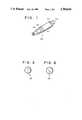
- FIG. 1is a perspective view of a valve structure according to the present invention
- FIG. 2is a front cross-sectional view of the valve of FIG. 1 to illustrate the positioning of the tubular member within the housing;
- FIG. 3is a side cross-sectional view of the valve of FIG. 1;
- FIG. 4is a perspective view of the valve of FIG. 1 with the exterior housing removed;
- FIGS. 5 and 6are views of disk prestressing means in octagonal and circular configurations, respectively.
- U.S. Pat. No. 4,684,364there is disclosed a flow control device having a tubular structure with input means and output means each provided with an open bore, channel means connecting the input and output bores and operating between open and closed positions, and clip means for retaining a portion of the channel means in a prestressed condition to obturate the channels means so as to maintain it in a closed position.
- the channel meansis forceable to an open position in response to a positive pressure in either one of the bores to facilitate flow through the channel means from the bore containing the positive pressure to the other bore.
- the flow control deviceis capable of passing fluid in either direction depending upon which bore contains the positive pressure, with the clip means returning the channel means to the closed position when the positive fluid pressure is removed.
- This inventionalso includes an intravenous system comprising a source of intravenous fluid, first catheter means for insertion into the vascular system of a patient, a pump for performing a pumping operation and urging the fluid from the source to the first catheter means, second catheter means coupling the pump to the source, and the flow control device described above located in at least the first catheter means.
- catheter meanscomprising an elongated body portion for insertion into a patient, at least one integral hub portion adjacent to the body portion, and at least one fluid flow control means located in either the body or hub portion or adjacent to the hub portion.
- the fluid flow control meansmay be integral with or releasably secured to its respective hub portion. Also, obturating means for rendering incompetent the fluid flow control means can be used.
- the catheter meansis intended for use in the methods disclosed in that patent. Such methods include preventing the introduction of ambient air into the vascular system of a patient when the catheter means is introduced into the patient's vascular system during intravenous or intra-arterial procedures, preventing the reflux of blood from the vascular system of the patient during such intravenous or intra-arterial procedures, and preventing the reflux of fluids into an organ or the pleural cavity of the patient when fluid directing means or catheter means are utilized for the removal of such fluids therefrom.
- FIGS. 1-4generally illustrate a fluid flow control means in the form of a valve arrangement 100.
- This valveincludes exterior housing 110 and inlet and outlet connectors 120 and 130, shown having leur lock connections for releasable attachment to a catheter, tubing, or the like. Therefore, the valve can be connected to the catheters or intravenous systems described in either patent referred to above.
- a male extension 122, 132which extends towards the center of the valve 100, is provided on the inlet and outlet connectors, 120, 130, respectively.
- a flexible tubular member 102formed of a silicon tube or the like provides a channel between the input and output connectors 120, 130. The ends of tubular member 102 fit over the respective male ends 122 and 132 of connectors 120 and 130.
- the center portion of this tube 102includes an internal disk member 104 which prestresses the tube and maintains it in a flattened condition in the area of the disk member.
- FIG. 3best illustrates the flattened condition of the tube.
- FIGS. 5 and 6show a detail of various disks 104 in an octagonal and circular configuration, respectively.
- the housing 140includes stop means 150, 152, in the form of an inwardly extending pin or plate, which maintains the distance between the input and output connectors at a predetermined distance when the valve is assembled.
- stop means 150, 152in the form of an inwardly extending pin or plate, which maintains the distance between the input and output connectors at a predetermined distance when the valve is assembled.
- the input and output connectorshave a corresponding hole or groove which matches the pin or plate of the housing 140.
- the housingis split into two portions as best shown in FIG. 1.
- the disk 104is initially placed inside the silicone tube 102 and the ends of the tube are then fitted around the male portion of the input and output connectors 120, 130.
- top and bottom sides of housing 140are placed around the input and output connectors and tube in a manner such that the stop means 150, 152 align properly with the groove means of the connectors.
- the two halves of the housing 140can be held together by retaining rings 160 which slide over the end connectors and onto the terminal ends of the housing.
- the housingcan be friction welded, ultrasonically welded, or glued with a suitable adhesive to create a permanent housing.
- the end connectors of this valvecan be attached to catheters, tubing (shown in FIG. 4 as 170), intravenous systems, or the like.
- cathetersshown in FIG. 4 as 170
- intravenous systemsor the like.
Landscapes
- Health & Medical Sciences (AREA)
- Emergency Medicine (AREA)
- Vascular Medicine (AREA)
- Engineering & Computer Science (AREA)
- Anesthesiology (AREA)
- Biomedical Technology (AREA)
- Heart & Thoracic Surgery (AREA)
- Hematology (AREA)
- Life Sciences & Earth Sciences (AREA)
- Animal Behavior & Ethology (AREA)
- General Health & Medical Sciences (AREA)
- Public Health (AREA)
- Veterinary Medicine (AREA)
- Infusion, Injection, And Reservoir Apparatuses (AREA)
- Media Introduction/Drainage Providing Device (AREA)
Abstract
Description
Claims (25)
Priority Applications (3)
| Application Number | Priority Date | Filing Date | Title |
|---|---|---|---|
| US07/050,589US4784644A (en) | 1986-01-13 | 1987-05-15 | Valve, catheter and method for preventing the introduction of air into the body of a patient |
| US07/269,829US4883461A (en) | 1987-05-15 | 1988-11-10 | Safety needle sheath in anti-reflux catheter having novel valve means |
| CA 583048CA1326420C (en) | 1986-01-13 | 1988-11-14 | Safety needle sheath in anti reflux catheter having novel valve means |
Applications Claiming Priority (2)
| Application Number | Priority Date | Filing Date | Title |
|---|---|---|---|
| US81843486A | 1986-01-13 | 1986-01-13 | |
| US07/050,589US4784644A (en) | 1986-01-13 | 1987-05-15 | Valve, catheter and method for preventing the introduction of air into the body of a patient |
Related Parent Applications (3)
| Application Number | Title | Priority Date | Filing Date |
|---|---|---|---|
| US06/484,205Continuation-In-PartUS4684364A (en) | 1983-04-12 | 1983-04-12 | Safety arrangement for preventing air embolism during intravenous procedures |
| US06/511,256Continuation-In-PartUS4568333A (en) | 1983-04-12 | 1983-07-06 | Valve arrangement especially suitable for preventing introduction of air into vascular systems |
| US81843486AContinuation-In-Part | 1983-04-12 | 1986-01-13 |
Related Child Applications (1)
| Application Number | Title | Priority Date | Filing Date |
|---|---|---|---|
| US07/269,829Continuation-In-PartUS4883461A (en) | 1987-05-15 | 1988-11-10 | Safety needle sheath in anti-reflux catheter having novel valve means |
Publications (1)
| Publication Number | Publication Date |
|---|---|
| US4784644Atrue US4784644A (en) | 1988-11-15 |
Family
ID=26728429
Family Applications (1)
| Application Number | Title | Priority Date | Filing Date |
|---|---|---|---|
| US07/050,589Expired - Fee RelatedUS4784644A (en) | 1986-01-13 | 1987-05-15 | Valve, catheter and method for preventing the introduction of air into the body of a patient |
Country Status (2)
| Country | Link |
|---|---|
| US (1) | US4784644A (en) |
| CA (1) | CA1326420C (en) |
Cited By (43)
| Publication number | Priority date | Publication date | Assignee | Title |
|---|---|---|---|---|
| WO1990005553A1 (en)* | 1988-11-14 | 1990-05-31 | Interface Biomedical Laboratories Corp. | Safety needle sheath in anti reflux catheter having novel valve means |
| US4935010A (en)* | 1986-11-20 | 1990-06-19 | Pharmacia Limited | Devices for sampling, drainage or infusion of liquids from or to the human or animal body |
| US5098406A (en)* | 1990-11-01 | 1992-03-24 | Interface Biomedical Laboratories Corp. | Anti-reflux, low friction, skirted hemostasis valve and introducer |
| US5562638A (en)* | 1993-06-21 | 1996-10-08 | Baxter International Inc. | Self-venting fluid system |
| US20030191453A1 (en)* | 2002-04-03 | 2003-10-09 | Velez Omar E. | Catheter assembly |
| US20040260271A1 (en)* | 2003-06-18 | 2004-12-23 | Huyser Richard F. | Extended fenestration catheter with internal coil and method of making the same |
| US20050113805A1 (en)* | 2003-11-20 | 2005-05-26 | Devellian Carol A. | Air embolization prevention system |
| US20050209572A1 (en)* | 2004-03-18 | 2005-09-22 | Guy Rome | Valved catheter |
| US20050209568A1 (en)* | 2004-03-16 | 2005-09-22 | Shanley Laurence M | Needle cap assembly for syringe |
| US20050288638A1 (en)* | 2004-06-23 | 2005-12-29 | Michel Thomas Iii | IV tubing with valve and method for use |
| US20060149293A1 (en)* | 2004-11-29 | 2006-07-06 | Eric King | Reduced-friction catheter introducer and method of manufacturing and using the same |
| US20080147181A1 (en)* | 2006-12-19 | 2008-06-19 | Sorin Biomedica Cardio S.R.L. | Device for in situ axial and radial positioning of cardiac valve prostheses |
| US20090069887A1 (en)* | 2007-09-07 | 2009-03-12 | Sorin Biomedica Cardio S.R.I. | Fluid-filled delivery system for in situ deployment of cardiac valve prostheses |
| US20090105652A1 (en)* | 2007-10-19 | 2009-04-23 | C. R. Bard, Inc. | Introducer including shaped distal region |
| US20090177163A1 (en)* | 2004-11-29 | 2009-07-09 | C. R. Bard, Inc. | Reduced friction catheter introducer and method of manufacturing and using the same |
| US7578803B2 (en) | 2004-03-18 | 2009-08-25 | C. R. Bard, Inc. | Multifunction adaptor for an open-ended catheter |
| US7637893B2 (en) | 2004-04-30 | 2009-12-29 | C. R. Bard, Inc. | Valved sheath introducer for venous cannulation |
| US20100036327A1 (en)* | 2008-08-08 | 2010-02-11 | Tandem Diabetes Care, Inc. | Flow prevention, regulation, and safety devices and related methods |
| US7854731B2 (en) | 2004-03-18 | 2010-12-21 | C. R. Bard, Inc. | Valved catheter |
| US20100331823A1 (en)* | 2009-06-26 | 2010-12-30 | C. R. Bard, Inc. | Proximally trimmable catheter including pre-attached bifurcation and related methods |
| US7875019B2 (en) | 2005-06-20 | 2011-01-25 | C. R. Bard, Inc. | Connection system for multi-lumen catheter |
| US7883502B2 (en) | 2004-03-18 | 2011-02-08 | C. R. Bard, Inc. | Connector system for a proximally trimmable catheter |
| US7993392B2 (en) | 2006-12-19 | 2011-08-09 | Sorin Biomedica Cardio S.R.L. | Instrument and method for in situ deployment of cardiac valve prostheses |
| US20110308650A1 (en)* | 2009-02-12 | 2011-12-22 | Farid Amirouche | Flow Control System for a Micropump |
| US8083728B2 (en) | 2004-03-18 | 2011-12-27 | C. R. Bard, Inc. | Multifunction adaptor for an open-ended catheter |
| US8177771B2 (en) | 2004-03-18 | 2012-05-15 | C. R. Bard, Inc. | Catheter connector |
| US8177770B2 (en) | 2004-04-01 | 2012-05-15 | C. R. Bard, Inc. | Catheter connector system |
| US8353953B2 (en) | 2009-05-13 | 2013-01-15 | Sorin Biomedica Cardio, S.R.L. | Device for the in situ delivery of heart valves |
| US8403982B2 (en) | 2009-05-13 | 2013-03-26 | Sorin Group Italia S.R.L. | Device for the in situ delivery of heart valves |
| US8771229B2 (en) | 2011-12-01 | 2014-07-08 | Picolife Technologies, Llc | Cartridge system for delivery of medicament |
| US8790307B2 (en) | 2011-12-01 | 2014-07-29 | Picolife Technologies, Llc | Drug delivery device and methods therefor |
| US8808367B2 (en) | 2007-09-07 | 2014-08-19 | Sorin Group Italia S.R.L. | Prosthetic valve delivery system including retrograde/antegrade approach |
| US8926564B2 (en) | 2004-11-29 | 2015-01-06 | C. R. Bard, Inc. | Catheter introducer including a valve and valve actuator |
| US8932260B2 (en) | 2004-11-29 | 2015-01-13 | C. R. Bard, Inc. | Reduced-friction catheter introducer and method of manufacturing and using the same |
| US9168105B2 (en) | 2009-05-13 | 2015-10-27 | Sorin Group Italia S.R.L. | Device for surgical interventions |
| US9883834B2 (en) | 2012-04-16 | 2018-02-06 | Farid Amirouche | Medication delivery device with multi-reservoir cartridge system and related methods of use |
| US10058313B2 (en) | 2011-05-24 | 2018-08-28 | Sorin Group Italia S.R.L. | Transapical valve replacement |
| US10130759B2 (en) | 2012-03-09 | 2018-11-20 | Picolife Technologies, Llc | Multi-ported drug delivery device having multi-reservoir cartridge system |
| US10245420B2 (en) | 2012-06-26 | 2019-04-02 | PicoLife Technologies | Medicament distribution systems and related methods of use |
| US11471647B2 (en) | 2014-11-07 | 2022-10-18 | C. R. Bard, Inc. | Connection system for tunneled catheters |
| US11504231B2 (en) | 2018-05-23 | 2022-11-22 | Corcym S.R.L. | Cardiac valve prosthesis |
| US11896782B2 (en) | 2017-08-23 | 2024-02-13 | C. R. Bard, Inc. | Priming and tunneling system for a retrograde catheter assembly |
| US12318289B2 (en) | 2018-05-23 | 2025-06-03 | Corcym S.R.L. | Device for the in-situ delivery of heart valve prosthesis |
Citations (4)
| Publication number | Priority date | Publication date | Assignee | Title |
|---|---|---|---|---|
| US605693A (en)* | 1898-06-14 | John l | ||
| US3298391A (en)* | 1967-01-17 | Two way flow anti-siphon valve assembly | ||
| US3324877A (en)* | 1963-12-30 | 1967-06-13 | Gen Electric | Check valve |
| US3572375A (en)* | 1967-06-02 | 1971-03-23 | David Rosenberg | Twin valve t-connector |
- 1987
- 1987-05-15USUS07/050,589patent/US4784644A/ennot_activeExpired - Fee Related
- 1988
- 1988-11-14CACA 583048patent/CA1326420C/ennot_activeExpired - Fee Related
Patent Citations (4)
| Publication number | Priority date | Publication date | Assignee | Title |
|---|---|---|---|---|
| US605693A (en)* | 1898-06-14 | John l | ||
| US3298391A (en)* | 1967-01-17 | Two way flow anti-siphon valve assembly | ||
| US3324877A (en)* | 1963-12-30 | 1967-06-13 | Gen Electric | Check valve |
| US3572375A (en)* | 1967-06-02 | 1971-03-23 | David Rosenberg | Twin valve t-connector |
Cited By (80)
| Publication number | Priority date | Publication date | Assignee | Title |
|---|---|---|---|---|
| US4935010A (en)* | 1986-11-20 | 1990-06-19 | Pharmacia Limited | Devices for sampling, drainage or infusion of liquids from or to the human or animal body |
| WO1990005553A1 (en)* | 1988-11-14 | 1990-05-31 | Interface Biomedical Laboratories Corp. | Safety needle sheath in anti reflux catheter having novel valve means |
| US5098406A (en)* | 1990-11-01 | 1992-03-24 | Interface Biomedical Laboratories Corp. | Anti-reflux, low friction, skirted hemostasis valve and introducer |
| US5562638A (en)* | 1993-06-21 | 1996-10-08 | Baxter International Inc. | Self-venting fluid system |
| US5814025A (en)* | 1993-06-21 | 1998-09-29 | Baxter International Inc. | Self-venting fluid system |
| US20030191453A1 (en)* | 2002-04-03 | 2003-10-09 | Velez Omar E. | Catheter assembly |
| US20040260271A1 (en)* | 2003-06-18 | 2004-12-23 | Huyser Richard F. | Extended fenestration catheter with internal coil and method of making the same |
| US8231604B2 (en) | 2003-11-20 | 2012-07-31 | W.L. Gore & Associates, Inc. | Air embolization prevention system |
| US20050113805A1 (en)* | 2003-11-20 | 2005-05-26 | Devellian Carol A. | Air embolization prevention system |
| US8882745B2 (en) | 2003-11-20 | 2014-11-11 | W.L. Gore & Associates, Inc. | Air embolization prevention system |
| US20050209568A1 (en)* | 2004-03-16 | 2005-09-22 | Shanley Laurence M | Needle cap assembly for syringe |
| US8083728B2 (en) | 2004-03-18 | 2011-12-27 | C. R. Bard, Inc. | Multifunction adaptor for an open-ended catheter |
| US7094218B2 (en) | 2004-03-18 | 2006-08-22 | C. R. Bard, Inc. | Valved catheter |
| US8177771B2 (en) | 2004-03-18 | 2012-05-15 | C. R. Bard, Inc. | Catheter connector |
| US7883502B2 (en) | 2004-03-18 | 2011-02-08 | C. R. Bard, Inc. | Connector system for a proximally trimmable catheter |
| US20050209572A1 (en)* | 2004-03-18 | 2005-09-22 | Guy Rome | Valved catheter |
| US8523840B2 (en) | 2004-03-18 | 2013-09-03 | C. R. Bard, Inc. | Connector system for a proximally trimmable catheter |
| US20110098653A1 (en)* | 2004-03-18 | 2011-04-28 | C. R. Bard, Inc. | Connector system for a proximally trimmable catheter |
| US7578803B2 (en) | 2004-03-18 | 2009-08-25 | C. R. Bard, Inc. | Multifunction adaptor for an open-ended catheter |
| US7854731B2 (en) | 2004-03-18 | 2010-12-21 | C. R. Bard, Inc. | Valved catheter |
| US8177770B2 (en) | 2004-04-01 | 2012-05-15 | C. R. Bard, Inc. | Catheter connector system |
| US8720065B2 (en) | 2004-04-30 | 2014-05-13 | C. R. Bard, Inc. | Valved sheath introducer for venous cannulation |
| US7637893B2 (en) | 2004-04-30 | 2009-12-29 | C. R. Bard, Inc. | Valved sheath introducer for venous cannulation |
| US9108033B2 (en) | 2004-04-30 | 2015-08-18 | C. R. Bard, Inc. | Valved sheath introducer for venous cannulation |
| US10307182B2 (en) | 2004-04-30 | 2019-06-04 | C. R. Bard, Inc. | Valved sheath introducer for venous cannulation |
| US20050288638A1 (en)* | 2004-06-23 | 2005-12-29 | Michel Thomas Iii | IV tubing with valve and method for use |
| US9101737B2 (en) | 2004-11-29 | 2015-08-11 | C. R. Bard, Inc. | Reduced friction catheter introducer and method of manufacturing and using the same |
| US9278188B2 (en) | 2004-11-29 | 2016-03-08 | C. R. Bard, Inc. | Catheter introducer including a valve and valve actuator |
| US8926564B2 (en) | 2004-11-29 | 2015-01-06 | C. R. Bard, Inc. | Catheter introducer including a valve and valve actuator |
| US9078998B2 (en) | 2004-11-29 | 2015-07-14 | C. R. Bard, Inc. | Catheter introducer including a valve and valve actuator |
| US8932260B2 (en) | 2004-11-29 | 2015-01-13 | C. R. Bard, Inc. | Reduced-friction catheter introducer and method of manufacturing and using the same |
| US10398879B2 (en) | 2004-11-29 | 2019-09-03 | C. R. Bard, Inc. | Reduced-friction catheter introducer and method of manufacturing and using the same |
| US8403890B2 (en) | 2004-11-29 | 2013-03-26 | C. R. Bard, Inc. | Reduced friction catheter introducer and method of manufacturing and using the same |
| US9283351B2 (en) | 2004-11-29 | 2016-03-15 | C. R. Bard, Inc. | Reduced friction catheter introducer and method of manufacturing and using the same |
| US20060149293A1 (en)* | 2004-11-29 | 2006-07-06 | Eric King | Reduced-friction catheter introducer and method of manufacturing and using the same |
| US9597483B2 (en) | 2004-11-29 | 2017-03-21 | C. R. Bard, Inc. | Reduced-friction catheter introducer and method of manufacturing and using the same |
| US20090177163A1 (en)* | 2004-11-29 | 2009-07-09 | C. R. Bard, Inc. | Reduced friction catheter introducer and method of manufacturing and using the same |
| US8206376B2 (en) | 2005-06-20 | 2012-06-26 | C. R. Bard, Inc. | Connection system for multi-lumen catheter |
| US8852168B2 (en) | 2005-06-20 | 2014-10-07 | C. R. Bard, Inc. | Connection system for multi-lumen catheter |
| US20110098679A1 (en)* | 2005-06-20 | 2011-04-28 | C. R. Bard, Inc. | Connection system for multi-lumen catheter |
| US7875019B2 (en) | 2005-06-20 | 2011-01-25 | C. R. Bard, Inc. | Connection system for multi-lumen catheter |
| US8617138B2 (en) | 2005-06-20 | 2013-12-31 | C. R. Bard, Inc. | Connection system for multi-lumen catheter |
| US8470024B2 (en) | 2006-12-19 | 2013-06-25 | Sorin Group Italia S.R.L. | Device for in situ positioning of cardiac valve prosthesis |
| US20080147160A1 (en)* | 2006-12-19 | 2008-06-19 | Sorin Biomedical Cardio S.R.L. | System for in situ positioning of cardiac valve prostheses without occluding blood flow |
| US7993392B2 (en) | 2006-12-19 | 2011-08-09 | Sorin Biomedica Cardio S.R.L. | Instrument and method for in situ deployment of cardiac valve prostheses |
| US9056008B2 (en) | 2006-12-19 | 2015-06-16 | Sorin Group Italia S.R.L. | Instrument and method for in situ development of cardiac valve prostheses |
| US8057539B2 (en) | 2006-12-19 | 2011-11-15 | Sorin Biomedica Cardio S.R.L. | System for in situ positioning of cardiac valve prostheses without occluding blood flow |
| US8070799B2 (en) | 2006-12-19 | 2011-12-06 | Sorin Biomedica Cardio S.R.L. | Instrument and method for in situ deployment of cardiac valve prostheses |
| US20080147181A1 (en)* | 2006-12-19 | 2008-06-19 | Sorin Biomedica Cardio S.R.L. | Device for in situ axial and radial positioning of cardiac valve prostheses |
| US20090069889A1 (en)* | 2007-09-07 | 2009-03-12 | Sorin Biomedica Cardio S.R.L. | Streamlined, apical delivery system for in situ deployment of cardiac valve prostheses |
| US8475521B2 (en) | 2007-09-07 | 2013-07-02 | Sorin Group Italia S.R.L. | Streamlined delivery system for in situ deployment of cardiac valve prostheses |
| US8808367B2 (en) | 2007-09-07 | 2014-08-19 | Sorin Group Italia S.R.L. | Prosthetic valve delivery system including retrograde/antegrade approach |
| US8114154B2 (en) | 2007-09-07 | 2012-02-14 | Sorin Biomedica Cardio S.R.L. | Fluid-filled delivery system for in situ deployment of cardiac valve prostheses |
| US20090069887A1 (en)* | 2007-09-07 | 2009-03-12 | Sorin Biomedica Cardio S.R.I. | Fluid-filled delivery system for in situ deployment of cardiac valve prostheses |
| US8486137B2 (en) | 2007-09-07 | 2013-07-16 | Sorin Group Italia S.R.L. | Streamlined, apical delivery system for in situ deployment of cardiac valve prostheses |
| US8608702B2 (en) | 2007-10-19 | 2013-12-17 | C. R. Bard, Inc. | Introducer including shaped distal region |
| US20090105652A1 (en)* | 2007-10-19 | 2009-04-23 | C. R. Bard, Inc. | Introducer including shaped distal region |
| US20100036327A1 (en)* | 2008-08-08 | 2010-02-11 | Tandem Diabetes Care, Inc. | Flow prevention, regulation, and safety devices and related methods |
| US8807169B2 (en)* | 2009-02-12 | 2014-08-19 | Picolife Technologies, Llc | Flow control system for a micropump |
| US8663538B2 (en) | 2009-02-12 | 2014-03-04 | Picolife Technologies, Llc | Method of making a membrane for use with a flow control system for a micropump |
| US20110308650A1 (en)* | 2009-02-12 | 2011-12-22 | Farid Amirouche | Flow Control System for a Micropump |
| US8764425B2 (en) | 2009-02-12 | 2014-07-01 | Picolife Technologies, Llc | Mold for making a membrane for use with a flow control system for a micropump |
| US8403982B2 (en) | 2009-05-13 | 2013-03-26 | Sorin Group Italia S.R.L. | Device for the in situ delivery of heart valves |
| US8353953B2 (en) | 2009-05-13 | 2013-01-15 | Sorin Biomedica Cardio, S.R.L. | Device for the in situ delivery of heart valves |
| US9168105B2 (en) | 2009-05-13 | 2015-10-27 | Sorin Group Italia S.R.L. | Device for surgical interventions |
| US20100331823A1 (en)* | 2009-06-26 | 2010-12-30 | C. R. Bard, Inc. | Proximally trimmable catheter including pre-attached bifurcation and related methods |
| US8337484B2 (en) | 2009-06-26 | 2012-12-25 | C. R. Band, Inc. | Proximally trimmable catheter including pre-attached bifurcation and related methods |
| US10058313B2 (en) | 2011-05-24 | 2018-08-28 | Sorin Group Italia S.R.L. | Transapical valve replacement |
| US8790307B2 (en) | 2011-12-01 | 2014-07-29 | Picolife Technologies, Llc | Drug delivery device and methods therefor |
| US9993592B2 (en) | 2011-12-01 | 2018-06-12 | Picolife Technologies, Llc | Cartridge system for delivery of medicament |
| US10213549B2 (en) | 2011-12-01 | 2019-02-26 | Picolife Technologies, Llc | Drug delivery device and methods therefor |
| US8771229B2 (en) | 2011-12-01 | 2014-07-08 | Picolife Technologies, Llc | Cartridge system for delivery of medicament |
| US10130759B2 (en) | 2012-03-09 | 2018-11-20 | Picolife Technologies, Llc | Multi-ported drug delivery device having multi-reservoir cartridge system |
| US9883834B2 (en) | 2012-04-16 | 2018-02-06 | Farid Amirouche | Medication delivery device with multi-reservoir cartridge system and related methods of use |
| US10245420B2 (en) | 2012-06-26 | 2019-04-02 | PicoLife Technologies | Medicament distribution systems and related methods of use |
| US11471647B2 (en) | 2014-11-07 | 2022-10-18 | C. R. Bard, Inc. | Connection system for tunneled catheters |
| US11896782B2 (en) | 2017-08-23 | 2024-02-13 | C. R. Bard, Inc. | Priming and tunneling system for a retrograde catheter assembly |
| US11504231B2 (en) | 2018-05-23 | 2022-11-22 | Corcym S.R.L. | Cardiac valve prosthesis |
| US11969341B2 (en) | 2018-05-23 | 2024-04-30 | Corcym S.R.L. | Cardiac valve prosthesis |
| US12318289B2 (en) | 2018-05-23 | 2025-06-03 | Corcym S.R.L. | Device for the in-situ delivery of heart valve prosthesis |
Also Published As
| Publication number | Publication date |
|---|---|
| CA1326420C (en) | 1994-01-25 |
Similar Documents
| Publication | Publication Date | Title |
|---|---|---|
| US4784644A (en) | Valve, catheter and method for preventing the introduction of air into the body of a patient | |
| US4684364A (en) | Safety arrangement for preventing air embolism during intravenous procedures | |
| US4722725A (en) | Methods for preventing the introduction of air or fluid into the body of a patient | |
| US4568333A (en) | Valve arrangement especially suitable for preventing introduction of air into vascular systems | |
| EP0927061B1 (en) | Valve apparatus for use with an iv set | |
| US4950254A (en) | Valve means for enteral therapy administration set | |
| CN109789291B (en) | Intravenous catheter apparatus with safety function and pressure control valve element | |
| US5098406A (en) | Anti-reflux, low friction, skirted hemostasis valve and introducer | |
| US7726328B2 (en) | Medical valve and method to monitor intra-abdominal pressure | |
| EP0334157B1 (en) | Implantable shunt system | |
| US5423769A (en) | Cardioplegia management system | |
| CA1127040A (en) | Intravenous pump filter protector | |
| US7094218B2 (en) | Valved catheter | |
| KR20060128967A (en) | Valve assembly | |
| JPH0566823B2 (en) | ||
| JP2004511270A (en) | Drip chamber anti-free flow device | |
| AU2001253883A1 (en) | Drip chamber anti free flow device | |
| US4661096A (en) | Anti-air embolism and antiblood loss device for CVP catheter | |
| US5217432A (en) | Automated drug infusion manifold | |
| EP0249423A3 (en) | Catheter for infusing fluid into a patient | |
| WO1998056440A1 (en) | Syringe and method for inflating low volume catheter balloons | |
| US5113911A (en) | Pressure actuated elastomeric valve | |
| CA1257162A (en) | Methods for preventing the introduction of air or fluid reflux into the body of a patient | |
| EP0099360A1 (en) | Safety valve for preventing air embolism or hemorrhage | |
| WO1990005553A1 (en) | Safety needle sheath in anti reflux catheter having novel valve means |
Legal Events
| Date | Code | Title | Description |
|---|---|---|---|
| AS | Assignment | Owner name:INTERFACE BIOMEDICAL LABORATORIES CORP., 7600 RIDG Free format text:ASSIGNMENT OF ASSIGNORS INTEREST.;ASSIGNOR:MILLER, LESTER F.;REEL/FRAME:004762/0011 Effective date:19870501 Owner name:INTERFACE BIOMEDICAL LABORATORIES CORP., 7600 RIDG Free format text:ASSIGNMENT OF ASSIGNORS INTEREST.;ASSIGNOR:SAWYER, PHILIP N.;REEL/FRAME:004762/0014 Effective date:19870501 Owner name:INTERFACE BIOMEDICAL LABORATORIES CORP.,NEW YORK Free format text:ASSIGNMENT OF ASSIGNORS INTEREST;ASSIGNOR:MILLER, LESTER F.;REEL/FRAME:004762/0011 Effective date:19870501 Owner name:INTERFACE BIOMEDICAL LABORATORIES CORP.,NEW YORK Free format text:ASSIGNMENT OF ASSIGNORS INTEREST;ASSIGNOR:SAWYER, PHILIP N.;REEL/FRAME:004762/0014 Effective date:19870501 | |
| AS | Assignment | Owner name:INTERFACE BIOMEDICAL LABORATORIES CORP., 7600 RIDG Free format text:ASSIGNMENT OF ASSIGNORS INTEREST.;ASSIGNOR:FITZGERALD, JOSEPH F.;REEL/FRAME:004762/0013 Effective date:19870512 Owner name:INTERFACE BIOMEDICAL LABORATORIES CORP.,NEW YORK Free format text:ASSIGNMENT OF ASSIGNORS INTEREST;ASSIGNOR:FITZGERALD, JOSEPH F.;REEL/FRAME:004762/0013 Effective date:19870512 | |
| FEPP | Fee payment procedure | Free format text:PAYOR NUMBER ASSIGNED (ORIGINAL EVENT CODE: ASPN); ENTITY STATUS OF PATENT OWNER: SMALL ENTITY | |
| FPAY | Fee payment | Year of fee payment:4 | |
| FPAY | Fee payment | Year of fee payment:8 | |
| REMI | Maintenance fee reminder mailed | ||
| LAPS | Lapse for failure to pay maintenance fees | ||
| FP | Lapsed due to failure to pay maintenance fee | Effective date:20001115 | |
| STCH | Information on status: patent discontinuation | Free format text:PATENT EXPIRED DUE TO NONPAYMENT OF MAINTENANCE FEES UNDER 37 CFR 1.362 |