US4784495A - System for preparing a fluid intended for a medical procedure by mixing at least one concentrate in powder form with water - Google Patents
System for preparing a fluid intended for a medical procedure by mixing at least one concentrate in powder form with waterDownload PDFInfo
- Publication number
- US4784495A US4784495AUS07/130,879US13087987AUS4784495AUS 4784495 AUS4784495 AUS 4784495AUS 13087987 AUS13087987 AUS 13087987AUS 4784495 AUS4784495 AUS 4784495A
- Authority
- US
- United States
- Prior art keywords
- fluid
- concentrate
- vessel
- conducting means
- water
- Prior art date
- Legal status (The legal status is an assumption and is not a legal conclusion. Google has not performed a legal analysis and makes no representation as to the accuracy of the status listed.)
- Expired - Lifetime
Links
- 239000012530fluidSubstances0.000titleclaimsabstractdescription430
- 239000012141concentrateSubstances0.000titleclaimsabstractdescription291
- XLYOFNOQVPJJNP-UHFFFAOYSA-NwaterSubstancesOXLYOFNOQVPJJNP-UHFFFAOYSA-N0.000titleclaimsabstractdescription193
- 238000002156mixingMethods0.000titleclaimsabstractdescription93
- 239000000843powderSubstances0.000titleclaimsabstractdescription89
- 238000000034methodMethods0.000titleclaimsabstractdescription33
- 238000011282treatmentMethods0.000claimsabstractdescription42
- 235000008504concentrateNutrition0.000claimsdescription281
- 239000000463materialSubstances0.000claimsdescription43
- 235000014483powder concentrateNutrition0.000claimsdescription41
- 239000007788liquidSubstances0.000claimsdescription34
- 230000001105regulatory effectEffects0.000claimsdescription31
- 230000037452primingEffects0.000claimsdescription30
- 235000014666liquid concentrateNutrition0.000claimsdescription27
- 238000004659sterilization and disinfectionMethods0.000claimsdescription25
- 239000012528membraneSubstances0.000claimsdescription24
- BVKZGUZCCUSVTD-UHFFFAOYSA-MBicarbonateChemical compoundOC([O-])=OBVKZGUZCCUSVTD-UHFFFAOYSA-M0.000claimsdescription22
- 238000011144upstream manufacturingMethods0.000claimsdescription19
- 239000002253acidSubstances0.000claimsdescription17
- FAPWRFPIFSIZLT-UHFFFAOYSA-MSodium chlorideChemical compound[Na+].[Cl-]FAPWRFPIFSIZLT-UHFFFAOYSA-M0.000claimsdescription14
- 239000000203mixtureSubstances0.000claimsdescription13
- 230000001276controlling effectEffects0.000claimsdescription11
- 239000002245particleSubstances0.000claimsdescription9
- 238000004891communicationMethods0.000claimsdescription8
- 230000002209hydrophobic effectEffects0.000claimsdescription8
- 239000011780sodium chlorideSubstances0.000claimsdescription7
- 239000000126substanceSubstances0.000claimsdescription7
- UIIMBOGNXHQVGW-UHFFFAOYSA-MSodium bicarbonateChemical compound[Na+].OC([O-])=OUIIMBOGNXHQVGW-UHFFFAOYSA-M0.000claimsdescription6
- 230000005855radiationEffects0.000claimsdescription5
- OYPRJOBELJOOCE-UHFFFAOYSA-NCalciumChemical compound[Ca]OYPRJOBELJOOCE-UHFFFAOYSA-N0.000claimsdescription3
- WQZGKKKJIJFFOK-GASJEMHNSA-NGlucoseNatural productsOC[C@H]1OC(O)[C@H](O)[C@@H](O)[C@@H]1OWQZGKKKJIJFFOK-GASJEMHNSA-N0.000claimsdescription3
- FYYHWMGAXLPEAU-UHFFFAOYSA-NMagnesiumChemical compound[Mg]FYYHWMGAXLPEAU-UHFFFAOYSA-N0.000claimsdescription3
- ZLMJMSJWJFRBEC-UHFFFAOYSA-NPotassiumChemical compound[K]ZLMJMSJWJFRBEC-UHFFFAOYSA-N0.000claimsdescription3
- WQZGKKKJIJFFOK-VFUOTHLCSA-Nbeta-D-glucoseChemical compoundOC[C@H]1O[C@@H](O)[C@H](O)[C@@H](O)[C@@H]1OWQZGKKKJIJFFOK-VFUOTHLCSA-N0.000claimsdescription3
- 239000011575calciumSubstances0.000claimsdescription3
- 229910052791calciumInorganic materials0.000claimsdescription3
- 239000008103glucoseSubstances0.000claimsdescription3
- 239000011777magnesiumSubstances0.000claimsdescription3
- 229910052749magnesiumInorganic materials0.000claimsdescription3
- 239000011591potassiumSubstances0.000claimsdescription3
- 229910052700potassiumInorganic materials0.000claimsdescription3
- 235000017557sodium bicarbonateNutrition0.000claimsdescription3
- 229910000030sodium bicarbonateInorganic materials0.000claimsdescription3
- DGAQECJNVWCQMB-PUAWFVPOSA-MIlexoside XXIXChemical compoundC[C@@H]1CC[C@@]2(CC[C@@]3(C(=CC[C@H]4[C@]3(CC[C@@H]5[C@@]4(CC[C@@H](C5(C)C)OS(=O)(=O)[O-])C)C)[C@@H]2[C@]1(C)O)C)C(=O)O[C@H]6[C@@H]([C@H]([C@@H]([C@H](O6)CO)O)O)O.[Na+]DGAQECJNVWCQMB-PUAWFVPOSA-M0.000claimsdescription2
- 239000011734sodiumSubstances0.000claimsdescription2
- 229910052708sodiumInorganic materials0.000claimsdescription2
- 150000003839saltsChemical class0.000claims15
- 230000000249desinfective effectEffects0.000claims12
- 230000000149penetrating effectEffects0.000claims3
- 238000002360preparation methodMethods0.000abstractdescription17
- 238000001631haemodialysisMethods0.000abstractdescription11
- 230000000322hemodialysisEffects0.000abstractdescription11
- 238000002615hemofiltrationMethods0.000abstractdescription8
- 239000000243solutionSubstances0.000description40
- 239000000385dialysis solutionSubstances0.000description17
- 238000010438heat treatmentMethods0.000description7
- 230000001954sterilising effectEffects0.000description7
- 239000008280bloodSubstances0.000description6
- 210000004369bloodAnatomy0.000description6
- 210000002445nippleAnatomy0.000description5
- 238000001556precipitationMethods0.000description5
- 238000000502dialysisMethods0.000description4
- 238000012544monitoring processMethods0.000description4
- 241000894006BacteriaSpecies0.000description3
- KRKNYBCHXYNGOX-UHFFFAOYSA-Ncitric acidChemical compoundOC(=O)CC(O)(C(O)=O)CC(O)=OKRKNYBCHXYNGOX-UHFFFAOYSA-N0.000description3
- 238000005259measurementMethods0.000description3
- VEXZGXHMUGYJMC-UHFFFAOYSA-NHydrochloric acidChemical compoundClVEXZGXHMUGYJMC-UHFFFAOYSA-N0.000description2
- 239000003513alkaliSubstances0.000description2
- 230000008901benefitEffects0.000description2
- 238000010168coupling processMethods0.000description2
- 238000005859coupling reactionMethods0.000description2
- 239000000645desinfectantSubstances0.000description2
- 238000004519manufacturing processMethods0.000description2
- 238000012986modificationMethods0.000description2
- 230000004048modificationEffects0.000description2
- -1salt compoundChemical class0.000description2
- UIIMBOGNXHQVGW-DEQYMQKBSA-MSodium bicarbonate-14CChemical compound[Na+].O[14C]([O-])=OUIIMBOGNXHQVGW-DEQYMQKBSA-M0.000description1
- 206010052428WoundDiseases0.000description1
- 208000027418Wounds and injuryDiseases0.000description1
- 230000002378acidificating effectEffects0.000description1
- 150000007513acidsChemical class0.000description1
- 150000001805chlorine compoundsChemical class0.000description1
- 238000004140cleaningMethods0.000description1
- 238000010276constructionMethods0.000description1
- 230000008878couplingEffects0.000description1
- 238000013461designMethods0.000description1
- 238000009792diffusion processMethods0.000description1
- 238000011010flushing procedureMethods0.000description1
- 230000006870functionEffects0.000description1
- 230000001771impaired effectEffects0.000description1
- 230000001788irregularEffects0.000description1
- 230000003907kidney functionEffects0.000description1
- 230000007246mechanismEffects0.000description1
- 125000000896monocarboxylic acid groupChemical group0.000description1
- 239000002574poisonSubstances0.000description1
- 231100000614poisonToxicity0.000description1
- 238000012545processingMethods0.000description1
- 239000008213purified waterSubstances0.000description1
- 238000001223reverse osmosisMethods0.000description1
- 239000012266salt solutionSubstances0.000description1
- 239000012047saturated solutionSubstances0.000description1
- 238000003860storageMethods0.000description1
- 239000008399tap waterSubstances0.000description1
- 235000020679tap waterNutrition0.000description1
- 238000000108ultra-filtrationMethods0.000description1
- 238000013022ventingMethods0.000description1
- 239000002699waste materialSubstances0.000description1
Images


Classifications
- A—HUMAN NECESSITIES
- A61—MEDICAL OR VETERINARY SCIENCE; HYGIENE
- A61M—DEVICES FOR INTRODUCING MEDIA INTO, OR ONTO, THE BODY; DEVICES FOR TRANSDUCING BODY MEDIA OR FOR TAKING MEDIA FROM THE BODY; DEVICES FOR PRODUCING OR ENDING SLEEP OR STUPOR
- A61M1/00—Suction or pumping devices for medical purposes; Devices for carrying-off, for treatment of, or for carrying-over, body-liquids; Drainage systems
- A61M1/14—Dialysis systems; Artificial kidneys; Blood oxygenators ; Reciprocating systems for treatment of body fluids, e.g. single needle systems for hemofiltration or pheresis
- A61M1/16—Dialysis systems; Artificial kidneys; Blood oxygenators ; Reciprocating systems for treatment of body fluids, e.g. single needle systems for hemofiltration or pheresis with membranes
- A61M1/1654—Dialysates therefor
- A61M1/1656—Apparatus for preparing dialysates
- A61M1/1666—Apparatus for preparing dialysates by dissolving solids
- A—HUMAN NECESSITIES
- A61—MEDICAL OR VETERINARY SCIENCE; HYGIENE
- A61M—DEVICES FOR INTRODUCING MEDIA INTO, OR ONTO, THE BODY; DEVICES FOR TRANSDUCING BODY MEDIA OR FOR TAKING MEDIA FROM THE BODY; DEVICES FOR PRODUCING OR ENDING SLEEP OR STUPOR
- A61M1/00—Suction or pumping devices for medical purposes; Devices for carrying-off, for treatment of, or for carrying-over, body-liquids; Drainage systems
- A61M1/14—Dialysis systems; Artificial kidneys; Blood oxygenators ; Reciprocating systems for treatment of body fluids, e.g. single needle systems for hemofiltration or pheresis
- A61M1/16—Dialysis systems; Artificial kidneys; Blood oxygenators ; Reciprocating systems for treatment of body fluids, e.g. single needle systems for hemofiltration or pheresis with membranes
- A61M1/1654—Dialysates therefor
- A61M1/1656—Apparatus for preparing dialysates
- A61M1/1668—Details of containers
- A—HUMAN NECESSITIES
- A61—MEDICAL OR VETERINARY SCIENCE; HYGIENE
- A61M—DEVICES FOR INTRODUCING MEDIA INTO, OR ONTO, THE BODY; DEVICES FOR TRANSDUCING BODY MEDIA OR FOR TAKING MEDIA FROM THE BODY; DEVICES FOR PRODUCING OR ENDING SLEEP OR STUPOR
- A61M1/00—Suction or pumping devices for medical purposes; Devices for carrying-off, for treatment of, or for carrying-over, body-liquids; Drainage systems
- A61M1/14—Dialysis systems; Artificial kidneys; Blood oxygenators ; Reciprocating systems for treatment of body fluids, e.g. single needle systems for hemofiltration or pheresis
- A61M1/16—Dialysis systems; Artificial kidneys; Blood oxygenators ; Reciprocating systems for treatment of body fluids, e.g. single needle systems for hemofiltration or pheresis with membranes
- A61M1/1654—Dialysates therefor
- A61M1/1656—Apparatus for preparing dialysates
- A61M1/1674—Apparatus for preparing dialysates using UV radiation sources for sterilising the dialysate
- B—PERFORMING OPERATIONS; TRANSPORTING
- B01—PHYSICAL OR CHEMICAL PROCESSES OR APPARATUS IN GENERAL
- B01F—MIXING, e.g. DISSOLVING, EMULSIFYING OR DISPERSING
- B01F35/00—Accessories for mixers; Auxiliary operations or auxiliary devices; Parts or details of general application
- B01F35/80—Forming a predetermined ratio of the substances to be mixed
- B01F35/82—Forming a predetermined ratio of the substances to be mixed by adding a material to be mixed to a mixture in response to a detected feature, e.g. density, radioactivity, consumed power or colour
- A—HUMAN NECESSITIES
- A61—MEDICAL OR VETERINARY SCIENCE; HYGIENE
- A61M—DEVICES FOR INTRODUCING MEDIA INTO, OR ONTO, THE BODY; DEVICES FOR TRANSDUCING BODY MEDIA OR FOR TAKING MEDIA FROM THE BODY; DEVICES FOR PRODUCING OR ENDING SLEEP OR STUPOR
- A61M2209/00—Ancillary equipment
- A61M2209/08—Supports for equipment
- A61M2209/082—Mounting brackets, arm supports for equipment
- B—PERFORMING OPERATIONS; TRANSPORTING
- B01—PHYSICAL OR CHEMICAL PROCESSES OR APPARATUS IN GENERAL
- B01F—MIXING, e.g. DISSOLVING, EMULSIFYING OR DISPERSING
- B01F23/00—Mixing according to the phases to be mixed, e.g. dispersing or emulsifying
- B01F23/40—Mixing liquids with liquids; Emulsifying
- Y—GENERAL TAGGING OF NEW TECHNOLOGICAL DEVELOPMENTS; GENERAL TAGGING OF CROSS-SECTIONAL TECHNOLOGIES SPANNING OVER SEVERAL SECTIONS OF THE IPC; TECHNICAL SUBJECTS COVERED BY FORMER USPC CROSS-REFERENCE ART COLLECTIONS [XRACs] AND DIGESTS
- Y10—TECHNICAL SUBJECTS COVERED BY FORMER USPC
- Y10T—TECHNICAL SUBJECTS COVERED BY FORMER US CLASSIFICATION
- Y10T137/00—Fluid handling
- Y10T137/2496—Self-proportioning or correlating systems
- Y10T137/2499—Mixture condition maintaining or sensing
Definitions
- the present inventionrelates to a system for preparing a fluid intended for a medical procedure and, more particularly, to a system for preparing such a fluid by mixing of at least one concentrate in powder form with water.
- the system of the present inventionis intended, in particular, for the preparation of fluids for use in connection with medical procedures such as hemodialysis, hemodiafiltration and hemofiltration.
- the system of the present inventionmay be used in connection with the preparation of a dialysis fluid for use in connection with hemodialysis, as well as used for preparation of replacement fluids used in connection with hemofiltration or hemodiafiltration.
- a fluid suitable for the treatmentis obtained from mixing of water with at least one concentrate in powder form, such as, for example, the production of flushing fluids for cleaning of wounds and the like.
- the blood of a patient suffering from impaired kidney functionis conducted along one side of a permeable membrane in a dialyzer device, at the same time as dialysis fluid is conducted along the opposite side of the same membrane.
- the poisons or other waste substances that are to be removed from the bloodpass with the help of diffusion from the blood of the patient to the dialysis fluid through the permeable membrane.
- a certain amount of fluidprimarily water, is also withdrawn from the blood so as to bring about a lowering of the weight of the patient.
- Hemodiafiltrationdiffers from hemodialysis first and foremost in that a more permeable filter membrane is utilized, Consequently, greater ultrafiltration or withdrawal of fluid from the body is obtained, which makes it necessary for a part of the ultrafiltrate removed to be replaced by a replacement fluid.
- Hemofiltrationdiffers from hemodialysis and hemodiafiltration in that no dialysis fluid is utilized on the opposite side of the permeable membrane along which the blood is conducted. Instead, with the help of a filter, a large quantity of ultrafiltrate is withdrawn from the blood across the filter membrane, which has to be replaced at least partly by a corresponding quantity of replacement fluid.
- control systemsare normally used for hemodialysis, hemodiafiltration and hemofiltration operations, respectively. However, they all have in common that at least one concentrate fluid is mixed with pure water in order to produce either the dialysis fluid in connection with hemodialysis operations, or the replacement fluids in connection with hemodiafiltration and hemofiltration operations.
- the concentrate to be mixed with wateris prepared in centralized preparation plants and is then transferred to the point of treatment in large kegs or other containers. Alternatively, the concentrate may be prepared directly on the spot in large tanks or the like before the treatment is to be started. Thus, in either instance, the concentrate to be used in the medical treatment is prepared in the form of a solution prior to actual use in connection with the medical treatment. At the time of treatment, the concentrate soultion is then mixed with water to provide the desired prepared solution for the particular medical treatment.
- the present inventionis directed to a system which overcomes or minimizes the aforementioned difficulties and problems of the prior art by providing a system for preparing a fluid intended for a medical procedure substantially at the time of use by mixing of at least one concentrate in powder form with water.
- the system of the present inventionincludes a source of water such as a reservoir, at least one vessel for containing a concentrate in powder form, and a concentrate fluid circuit for withdrawing a small quantity of water from the source of water and passing same through the vessel containing the concentrate in powder form in order to dissolve the concentrate to produce a concentrate fluid, and for then conducting the concentrate fluid to a primary fluid circuit to be mixed with the rest of the water withdrawn from the source of water.
- primary or first fluid conducting meanshaving one end communicating with the source of water for withdrawing water from the source and a second end for delivering a prepared solution.
- the concentrate fluid circuitincludes second fluid conducting means which communicates with the source of water and with an inlet to the vessel containing the concentrate in powder form for introducing water from the source of water into the vessel to produce a concentrate fluid containing dissolved powder concentrate and water, and third fluid conducting means which communicates with the outlet of the vessel and with a mixing point in the first fluid conducting means intermediate the first and second ends thereof for conducting the produced concentrate fluid from the vessel into the first fluid conducting means to be mixed with water being conducted therethrough, to thereby produce the prepared solution for delivery to the second end of the first fluid conducting means.
- Measuring meansare provided in the first fluid conducting means downstream of the mixing point for measuring the composition of prepared solution obtained by mixing of the produced concentrate fluid and water being conducted through the first fluid conducting means, and flow regulating means are provided in the third fluid conducting means which is responsive to the measuring means for controlling the flow of concentrate fluid from the vessel.
- the systemalso includes a source of second concentrate fluid, and fourth fluid conducting means having a first end communicating with the source of second concentrate fluid and a second end communicating with the primary or first fluid conducting means at a second mixing point intermediate the first and second ends thereof for introducing the second concentrate fluid into the primary fluid conducting means to be mixed with fluid being conducted therethrough to produce the prepared solution downstream of the first and second mixing points, the prepared solution thus being comprised of first concentrate fluid produced by conducting water from the source of water into the vessel containing the concentrate in powder form and second concentrate fluid from the source thereof, both of which are mixed with water withdrawn from the source of water through the primary fluid conducting means.
- the systemincludes first and second vessels each containing a concentrate in powder form, the two concentrates being different from one another.
- the two vesselsare adapted to be connected in the concentrate fluid circuit through the use of first and second connection means.
- the first connection meansis provided at a first location in the concentrate fluid circuit for connecting the first vessel to the concentrate fluid circuit so as to introduce fluid containing water from the source of water into the first vessel to dissolve the first concentrate therein and to withdraw the dissolved first concentrate therefrom
- the second connection meansis provided at a second location in the concentrate fluid circuit for connecting the second vessel to the concentrate fluid circuit so as to introduce fluid containing water from the source of water into the second vessel to dissolve the second concentrate and to withdraw fluid containing the dissolved second concentrate from the second vessel.
- the first and second connection meansare different from one another so that the first vessel is only connectable by the first connection means to the concentrate fluid circuit at the first location, and the second vessel is only connectable by the second connection means to the concentrate fluid circuit at the second location.
- the first and second connection meanscomprise first and second holders, with the first holder being configured to only hold a vessel having the configuration of the first vessel, and the second holder being configured to only hold a vessel having the configuration of the second vessel.
- the vessel containing the concentrate in powder formincludes an inlet at the top thereof and an outlet at the bottom thereof, with the vessel being arranged in the concentrate fluid circuit so that water withdrawn from the source of water is introduced into the top of the vessel to produce a concentrate fluid containing dissolved powder concentrate, and so that the produced concentrate fluid is withdrawn from the bottom of the vessel and conducted to the primary fluid conducting means to be mixed with water being conducted therethrough to produce the prepared solution.
- wateris conducted through the vessel from the top thereof to the bottom thereof to thereby maintain and provide a relatively constant concentration level of dissolved powder concentrate being introduced into the primary fluid conducting means.
- the solution or fluid for the medical treatmentcan thus be prepared directly at the point of treatment and substantially at or just prior to treatment beginning.
- Such a system in accordance with the present inventionthus avoids the necessity of preparing large quantities of concentrate solutions in liquid form, which would otherwise result in some of the concomitant problems mentioned hereinabove.
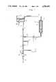
- FIGS. 1-4illustrate four alternative embodiments of the system in accordance with the present invention for preparing a fluid for a medical procedure by mixing of a concentrate in powder form with water.
- FIG. 5illustrates a further alternative arrangement for the system of the present invention in which the fluid is prepared starting with one concentrate in powder form and a second concentrate in liquid form.
- FIG. 6illustrates a still further arrangement for the system in accordance with the present invention which again utilizes a concentrate in powder form and a concentrate in liquid form, the system of FIG. 6 being particularly adapted for use in connection with a hemodialysis-type of treatment.
- FIG. 7illustrates a cartridge intended to be used in any of the alternative system arrangements shown in FIGS. 1-6, the cartridge being shown mounted in a holder therefor.
- FIG. 8illustrates a still further arrangement for the system in accordance with the present invention in which two different concentrates in powder form are utilized in connection with a further concentrate in liquid form for preparing a fluid for a medical procedure.
- the dialysis fluid in accordance with the present inventiontypically may comprise a purified solution containing bicarbonate, such as sodium bicarbonate, together with salt compound such as sodium chloride or, optionally, other alkali or other alkali earth chlorides.
- bicarbonatesuch as sodium bicarbonate
- salt compoundsuch as sodium chloride or, optionally, other alkali or other alkali earth chlorides.
- a primary fluid conduit or duct 1which originates from a suitable source of water, such as a liquid reservoir 2.
- the liquid reservoir 2includes an inlet 15 for introduction of pure water thereinto, for example, from a reverse osmosis unit.
- the main conduit 1is provided with a throttling mechanism or device 3, a pressure gauge 4, a pump 5 and a deaerating device 6.
- the deaeration device 6typically is provided with an air outlet 16. This outlet may be in direct communication with the atmosphere, but, preferably, is in communication with a discharge via a suction pump (not shown).
- the main duct 1includes an outlet 17 for the prepared solution obtained in the manner described more fully hereinbelow.
- the outlet 17 for the prepared solutionmay, for example, be passed directly to one side of a dialyzer unit.
- the systemalso includes a concentrate fluid circuit which, for example, may be comprised of a fluid conduit or duct 8 which originates at one end from the liquid reservoir 2, such as by means of a suction nozzle 9 which has been inserted thereinto.
- the other end of the concentrate fluid duct 8joins the main fluid line 1 at a mixing point 7 which is intermediate the reservoir 2 and the outlet end 17 of the main line 1.
- the concentrate fluid conduit 8includes therein a column or vessel 10 which contains a concentrate 11 in powder form arranged between two particle filters 12. In operation, a portion of the water in the reservoir 2 is drawn off through the concentrate fluid circuit 8 and is introduced into the top of the column or vessel 10 to be conducted downwardly toward the bottom thereof.
- the concentrate line 8 and column 10are suitably dimensioned in such a manner that as the water drawn into the concentrate fluid circuit 8 is conducted downwardly through the column 10, a substantially saturated solution of the powder concentrate in water is obtained, to thus produce a concentrate fluid which is then conducted from the column 10 and introduced into the main line 1 at mixing point 7.
- a flow regulating device 13is provided in the portion of the concentrate fliud conduit 8 intermediate the column 10 and mixing point 7 for controlling the flow of the produced concentrate solution from the column 10 into the main line 1.
- a conductivity meter or other measuring device 14is provided in the main line 1 downstream of the mixing point 7 for monitoring the composition of the prepared solution and for then controlling the flow regulating device 13.
- the measuring device 14could measure a different property or parameter, such as temperature, pH, or even some other parameter.
- the flow regulating device 13may conveniently comprise a simple adjustable throttling device as shown in FIG. 1. This is advantageous in that it results in a simple overall design for the system since a single pump 5 can be employed for withdrawing water from the reservoir for both the main flow through line 1 and for production of the concentrate fluid in fluid conduit 8. Specifically, by arranging the pump 5 for the suction of water in the main line 1 downstream of the mixing point 7, the pump 5 serves to withdraw water from the reservoir 2 partly through the main line 1, and partly indirectly from the same source via the concentrate fluid circuit 8. Further, with the throttling device 3 provided in the main line 1 between the source of water and the mixing point 7, and the deaerator device 6 is located in the main duct downstream of the pump 5, as shown in FIG.
- the same pump 5can also be used for deaeration of the prepared fluid.
- the pump 5is operative to handle flow rates up to at least 500 ml/min, and more preferably, up to approximately 1,000 ml/min, in the main line 1 downstream of mixing point 7, whereas the flow regulating means 13 is operative to handle flow rates up to approximately 40 ml/min and, in any event, at least 30 ml/min at flow rates or approximately 1,000 ml/min in the main line 1.
- FIG. 2operates in principle in the same manner as that according to FIG. 1.
- the same reference numeralshave been utilized for corresponding components as were used with respect to the embodiment shown in FIG. 1.
- such componentshave been indicated through the use of the letter "a" after the referenc numeral.
- FIG. 2differs from that according to FIG. 1 mainly through the employment of a mixing pump 13a as the flow regulating device, in place of the throttle device 13 employed in the embodiment of FIG. 1.
- a vent opening 18is provided which is preferably arranged at or near the top of the powder concentrate column or vessel 10.
- a suction line or duct 19is connected at one end to the vent 18 and at the other end to the concentrate conduit 8 at a point upstream of the suction pump 13a.
- the suction line 19also includes a hydrophobic filter 20 therein.
- suction pressureis produced appropriately in the suction line 19 through the aid of the pump 13a which thus facilitates deaeration of the system, especially during start-up.
- the column 10When the column 10 has been totally deaserated, by liquid drawn into the line 19 will be blocked or stopped upon reaching the hydrophobic filter 20 and, thus, liquid will only be withdrawn from the column 10 via the concentrate conduit 8. Should any new air or other gas be formed in the column 10 during operation, this normally would remain in the uppermost part of the column 10 and, therefore, will not disturb any subsequent measurement.
- the system according to FIG. 2may also include means (not shown) for the deaeration of the main stream being conducted through the primary or main line 1.
- the system according to FIG. 3also corresponds in principle to that illustrated in FIGS. 1 and 2 and, therefore, the same reference numerals have been used with respect to the same components. Modified components have been indicated through the use of the additional letter "b".
- the system of FIG. 3differs from that of FIG. 2 in that the deaeration or suction line 19 has been replaced with a deaeration line 19b which includes a hydrophobic filter 20 arranged therein together with an adjustable throttle device 21.
- the line 19bdoes not open directly into the concentrate conduit 8, but rather, communicates with the main line 1 immediately upstream of the pump 5 and downstream of the throttle device 3.
- the throttle device 21preferably is adapted so that it is capable of being closed completely when deaeration of the column 10 has been completed.
- FIG. 4shows a further alternative arrangement for the concentrate powder column 10 and suction duct 19.
- the hydrophobic filter 20has been replaced by or alternatively used in combination with, an expansible body or material 22 provided within the housing therefor, designated by the reference character 20c, which is adapted to expand upon water being drawn into the housing 20c to thus close off further flow therethrough.
- the line 19is effectively closed after complete deaeration by means of the expansion of the body 22.
- a separate venting arrangementis provided in the column 10. More particularly, the column 10 is provided with a separate vent opening 18 which preferably is arranged at or near the highest point of the column 10. Deaeration of the system is further facilitated through the aid of a suction line 19 originating from the vent opening 18 in the column and preferably provided with a hydrophobic filter or other shut-off device for the fluid. In this manner, any irregular discharge during normal operation of fluid concentrate through the suction line 19 is prevented. Further, the suction duct 19 connected to the vent opening 18 in the column 10 can communicate either with the concentrate conduit 8 or directly with the main line 1. In each instance, such communication should take place appropriately just upstream of the suction pump 13a or 5 installed in the respective conduit 8 or 1.
- wateris introduced into the concentrate powder column 10 at the top of the column 10 and conducted downwardly to the bottom thereof. This is preferable in order to maintain and provide a relatively constant concentration level of dissolved powder concentrate into the primary fluid line 1.
- water withdrawn into the concentrate fluid line 8could be conducted through the powder column 10 from the bottom toward the top, both in connection with normal operation as well as in connection with initial priming of the system.
- the primary fluid line 1 and concentrate fluid line 8could both be connected directly to a source of water such as a tap water system, for example, by means of a T-coupling, instead of to a reservoir which is supplied with water.
- a source of watersuch as a tap water system
- the primary fluid line 1 and concentrate fluid line 8could be connected to different sources of water, although it is preferable that they both be connected to a common source of water such as reservoir 2 as shown in FIGS. 1-4.
- the solution for a medical procedure or treatmentis to be prepared from more than one concentrate, such as, for example, the dialysis solution disclosed in the aforementioned European patent specification EP-B1-0 022 922.
- the more stable concentratemay be provided in a liquid form and the less stable concentrate or concentrates provided in powder form.
- FIG. 5illustrates a modified system in accordance with the present invention for preparing a solution for a medical procedure or treatment in which the solution is prepared from one concentrate in powder form and one concentrate in liquid form.
- the same reference charactershave been used as in the remaining figures., but with the added letter "d" being used to designate modified components.
- a suitable reservoir 2is provided from which fluid for preparing a solution is conducted, on the one hand, via a main or primary conduit 1 and, on the other hand, through a concentrate circuit or conduit 8d containing a powder concentrate column 10d therein.
- the concentrate conduit 8dcommunicates with the main conduit 1 at a mixing point 7.
- Means for regulating the flow of fluid in the main conduit 1 and for deaeration, respectively,have been indicated by a single rectangle marked 3d, 5d, 6d.
- a conductivity meter or other measuring deviceis provided in the main control 1, as indicated by the reference numeral 14d.
- the conductivity meter or other measuring device 14dis adapted to control a flow regulating device 13d provided in the concentrate conduit 8d downstream of the powder concentrate column 10d.
- the flow regulating devicecomprises a throttle, such as throttle 13 shown in FIG. 1, the throttle device 3d should be located upstream of the mixing point 7.
- a second mixing point 23is provided downstream of the conductivity meter 14d.
- a second concentrate fluidis introduced into the main duct via a second concentrate conduit or duct 24 which communicates with a source of second concentrate 25, which, in this instance, is in a liquid form.
- the flow of concentrate through the second concentrate duct 24is regulated with the aid of a conductivity meter or other measuring device 26 provided in the main conduit 1 and which controls a flow regulating device 27 provided in the second concentrate duct 24.
- a pH meter 28may be installed in the main conduit 1. If conductivity, pH, temperature, or any other parameter utilized for controlling the flow of concentrates through their respective conduits 8d, 24 do not agree or correspond with the desired value, the prepared fluid is passed via a bypass valve 29 directly to a discharge (not shown). If, on the other hand, all of the parameters are correct or in accordance with their desired values, the prepared solution is passed via valve 30 to the actual point of treatment, for example, a dialyzer.
- conductivity meters or other measuring devices 14d, 26 for accurate monitoring of the composition of the prepared solution upstream as well as downstream of the second mixing point 23may appropriately be arranged in the main duct 1 and, in particular, arranged downstream of the respective mixing point 7 with which the concentrate conduit 8d communicates.
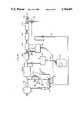
- FIG. 6shows a still further modified system in accordance with the principles of the present invention which is particularly intended for use in connection with preparation of a dialysis fluid for use in connection with a hemodialysis operation.
- the same reference charactershave been used to designate like components, with the added character “e” being included with respect to modified components.
- the system shown in FIG. 6is similar to that in accordance with FIG. 5 in that it is used to prepare a solution from two different concentrates, one in liquid form and one in powder form.
- the system of FIG. 6differs from FIG. 5, however, with respect to the location the concentrate fluids obtained from the liquid and powder sources are introduced into the main duct or conduit 1.
- water for use in preparing the dialysis fluidis introduced to a heating vessel or reservoir 2 for heating the water to the desired temperature.
- the heating vessel or reservoir 2From the heating vessel or reservoir 2, the main part of the water used in preparing the dialysis fluid is conducted from the reservoir 2 through a main or primary conduit 1.
- the flowis degased by means of a throttle 3e, and a pump 5e and a deaerator 6e, shown together in FIG. 6 as a single rectangle.
- a liquid concentrate line or duct 24ecommunicates with the main conduit 1 at a mixing point 23e downstream of the throttle 3e and the rectangle 5e, 6e.
- the concentrate duct 24eincludes a concentrate pump 27e therein which pumps a liquid concentrate from a liquid concentrate container 25e.
- the conductivity of the mixture after introduction of the liquid concentrateis measured in the main conduit 1 by means of a conductivity meter 26e which controls the pump 27e.
- a smaller portion of the water in the reservoir 2is fed through a concentrate fluid circuit comprised of a concentrate conduit 8e.
- a column or vessel 10 containing a concentrate in powder formis provided in the concentrate conduit 8e so that, as with the other embodiments discussed hereinabove, the smaller portion of water withdrawn from the reservoir 2 is fed through the column 10 from the top toward the bottom therof, and from there through a continuation of the concentrate conduit 8e to a concentrate pump 13e.
- the concentrate fluid obtained from the vessel 10is then conducted to the main conduit 1 at a mixing point 7e where it is mixed with the main flow of water from the reservoir 2, which includes the liquid concentrate therein.
- the conductivityis thereafter measured once again, utilizing the conductivity meter 14e which controls the pump 13e in the concentrate conduit 8e.
- a pH meter 28e and a third conductivity meter 31eare arranged in the main conduit 1 downstream of the second mixing point 7e, but upstream of a bypass valve 29e and a main valve 30e through which the system may be connected to a dialyzer. If the measurements obtained in the main conduit 1 from the conductivity meters 26e, 14e, 31e and/or the pH meter 28e are not in accord with the desired values, the main valve 30e is closed and valve 29e opened. For this purpose, the conductivity meters 26e, 14e, 31e and pH meters 28e are all shown as controlling valves 29e and 30e.
- valves 29e and 30eperferably control the various meters for measuring the properties of the fluid being conducted through main conduit 1
- the system shown in FIG. 6also includes means for initial priming of the system and, in particular, the powder concentrate column, as well as means for disinfection or sterilization of the system. More particularly, downstream of the powder concentrate column 10, there is provided a bypass or priming line 66 connected to the concentrate conduit 8e and the main conduit 1 downstream of the throttle 3e and upstream of the pump/deaerator rectangle 5e, 6e. A valve 32 is provided at the point that the priming line 66 is connected to the concentrate conduit 8e. When the system, especially the dry column 10, is to be initially primed with water from the heating vessel or reservoir 2, the valve 32 is opend together with a second valve 33, both controlled by a pressure switch or button 34.
- the two valves 32, 33are kept upon until water reaches the point 35 where the bypass line joins the concentrate conduit 8e. Thereafter, the two valves 32, 33 are closed and the water, which is now a concentrate fluid containing dissolved powder concentrate therein, may continue through the concentrate conduit 8e to the pump 13e.
- An adjustable throttling device 41may also be provided in the priming line 66 in parallel to the valve 33. This arrangement thus facilitates initial dearation of the system by virtue of air being drawn from the vessel and introduced into the mainline 1 upstream of the deaerator 6e.
- the powder concentrate vessel or column 10is removed from the concentrate fluid circuit 8e, and the ends of the concentration conduit 8e normally connected to the vessel 10 are instead connected to connection points 36 adn 37, respectively, of separate sterilization conduits or lines 40 and 42.
- the liquid concentrate container 25eis also removed, and the concentrate duct 24e connected to a connection point 38e in fluid communication with the sterilization line 42.
- the start point 39 of the concentrate conduit 8enormally connected to the heating vessel or reservoir 2, is instead connected to a source of disinfection liquid (not shown). In this manner, disinfection liquid is fed through the starting branch of the concentrate conduit 8e to the connection point 36 where it is conducted through the sterilization line 40 to the valve 32.
- the disinfection liquidis conducted either through the valve 33 or through the parallel valve 41, in the nature of an adjustable throttling device, to the main conduit 1.
- the disinfection liquidthen passes through the throttle device 3e, pump 5e and dearearato 6e until it reaches the mixing point 23e.
- the concentrate line 24enow connectd to connection point 38e in the sterilization conduit 42, serves to conduct the disinfection liquid through line 42 to the point 37 which is attached to the lower part of the concentrate conduit 8e.
- the disinfection liquidcontinues through the concentration conduit 8e via pump 13e and back to the main conduit 1, where it meets the rest of the flow of disinfection liquid being conducted through the main conduit 1 from the mixing point 23e.
- the disinfection liquidthen continues through the main conduit 1 to the end valve 30e.
- the additional disinfectant conduits 40, 42are suitably arranged and connected to the remaining components of the system to insure that disinfection solution is conducted throughout all of the reusable components, namely, the conduit lines 1, 8e, 24e, the various meters 14e, 26e, 28e, 31e, and de-gasing and deaeration devices and pumps 3e, 5e, 6e, 13e, 27e.
- the powder concentrate columns or vessels 10 utilized in the various embodiments described hereinabovemay conveniently be in the form of a self-contained cartridge containing a quantity of powder concentrate therein suitable for use one treatment procedure, the cartridge being totally closed and provided with penetrable membranes at its upper inlet and its lower outlets which are adapted to be penetrated by suitable connection devices for the ends of the conduit in the fluid concentrate circuit 8 or 8d or 8e.
- the cartridgeis internally sterile, such as by having been exposed to radiation such as gamma radiation.
- FIG. 7shows such a cartridge 10f, as well as a holder 43 therefor, which is specially constructed to accommodate a cartridge of a particular configuration.
- the cartridge column 10fcomprises a closed vessel provided with penetrable membranes 62, 64 at its upper inlet end and its lower outlet end, respectively.
- a supply of powder concentrateof sufficient quantity so as to be suitable for a single treatment.
- the concentrate in powder formmay consist of sodium bicarbonate material, and the quantity thereof contained in the cartridge would be on the order of magnitude of 400-900 grams and, more preferably, approximately 600 grams.
- the contents of the cartridge 10fare preferably sterilized, such as by means of gamma radiation.
- the particles of powdershould be of a size of at least 100 microns ( ⁇ ), and preferably larger than 150 microns ( ⁇ ).
- ⁇microns
- ⁇microns
- the cartridge 10fis adapted to be mounted in a holder 43 provided with a pair of upper and lower swinging arms 44 and 45 mounted on a suitable support structure 60.
- the arms 44, 45are provided with spike connectors 46 and 47, respectively, which are intended to penetrate the membranes 62, 64 at the upper inlet and the lower outlet of the closed cartridge vessel 10f.
- the upper inlet and lower outlet of the cartridge 10fare each provided with an outwardly portruding nipple having the penetrable membranes 62, 64 therein, which nipples are adapted to be received in suitable recesses in the arms 44, 45 so that the end of the spike connectors 46, 47 may penetrate same when the arms 44, 45 are swung into essentially horizontal positions to hold the cartridge 10f.
- the spacing between the arms 44, 45is such as to corresond to the height of the cartridge 10f.
- the upper or inlet spike 46is intended to be connected to the conduit in the concentrate fluid circuit 8e which is upstream of the cartridge 10 as shown in FIG.
- connection of the cartridge 10f in the circuit 8eis accomplished relatively easily by moving the arms 44, 45 apart, positioning the cartridge 10f therebetween and then moving the arms 44, 45 into horizontal, parallel, positions so that the spikes 46, 47 penetrate the membranes 62, 64.
- FIG. 7it is a relatively simple operation to remove the cartridge 10f and to connect the spike 46 to a nipple 48 and the spike 47 to a nipple 49 mounted on the support structure 60 for the cartridge 10f.
- the nipples 48 and 49correspond to the connection points 36 and 37, respectively, which are schematically shown in FIG. 6.
- each of the columns 10 for the respective powder concentratesmay be of a distinct configuration, such as, distinct with regard to shape, the manner of connection or some other like manner, so that each column or other vessel 10 of powder concentrate which is to be connected to the system may only be connected at the correct point or location within the system. Conveniently, this may be accomplished through the use of different size cartridges 10f and different holders 43 of the type shown in FIG. 7 in which the spacing between the arms 44, 45 is different for the respective, different size cartridge 10f containing powder concentrates.
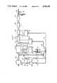
- FIG. 8schematically shows a still further arrangement for a system in accordance with the present invention in which two different substances in the form of powder concentrates, as well as a liquid concentrate, are used in preparing a solution for a medical treatment.
- the same reference charactersare used in FIG. 8, but with the addition of the character "g" thereafter to indicate modified components.
- the system of FIG. 8is particularly useful in connection with preparing a dialysis fluid for a dialysis operation which includes two columns or vessels of powder material, one including a bicarbonater material and one including a salt solution, such as sodium chloride, as well as a liquid concentrate such as acid.
- the two columns 10g 1 and 10g 2 containing powder concentrateare in the form of self-contained cartridges similar to that shown in FIG. 7, except that they are of different sizes.
- cartridge 10g 1has a shorter height than cartridge 10g 2 .
- the cartridges 10g 1 and 10g 2are arranged in parallel to one another in the concentrate fluid circuit 8g so that each will receive a portion of the water directed from the heating vessel or reservoir 2.
- the water withdrawn from the reservoir 2 through the concentrate fluid circuit 8gflows through the respective cartridges 10g 1 and 10g 2 to thus produce two concentrate fluid, each comprised of powder concentrate dissolved in water.
- Wateris also withdrawn from the heating vessel or reservoir 2 through a main line 1.
- the concentrate fluids obtained from the two vessels 10g 1 and 10g 2are returned to the main line 1 at two different mixing points, 23g and 7g, respectively, with the mixing points 23g, 7g being separated from one another and with a conductivity meter 26g provided therebetween.
- Liquid concentratesuch as an acid
- the concentrate from the drip counter 52is conducted to the main line or conduit 1 at a mixing point 53 which is upstream of the first mixing point 23g.
- a further conductivity meter or pH-meter(not shown) may be provided. However, such a meter is not necessary if the pump 51 for the acid is controlled precisely.
- the concentrate fluid circuit 8gincludes two parallel branch lines 8g 1 and 8g 2 , with one cartridge 10g 1 being arranged in one branch line 8g 1 , and the other cartridge 10g 2 arranged in the other branch line 8g 2 .
- a holdersuch as holder 43 shown in FIG. 7 but sized to accommodate cartridge 10g 1 can be used to hold cartridge 10g 1 in position in branch line 8g 1
- a larger sized holdercan be used to hold cartridge 10g 2 in branch line 8g 2 .
- connection meanssuch as different manners of connecting the conduits to the cartridge 10g 1 , 10g 2 , particular shapes for the cartridges and holder therefor, or other special configurations, could be used for insuring that the cartridges can be connected to the system only at the correct locations.
- Branch line 8g 1includes a pump 13g therein downstream of cartridge 10g 1 for conducting concentrate fluid produced in cartridge 10g 1 to the main conduit 1 at mixing point 7g
- brand line 8g 2includes a pump 27g therein downstream of cartridge 10g 2 for conducting concentrate fluid produced in cartridge 10g 2 to the main conduit 1 at mixing point 23g.
- a separate priming line 66gis also provided, connected to each of the branch lines 8g 1 , 8g 2 via means of vavles 32g 1 , 32g 2 downstream of the respective cartridges 10g 1 , 10g 2 and communicating with main line 1 intermediate the throttle device 3g and the pump/deaerator rectangle 5g, 6g.
- the priming line 66gis for a similar purpose as the priming line 66 shown in FIG. 6.
- the cartridge 10g 1may contain a bicarbonate material in powder form, such as sodium bibarbonate, whereas the cartridge 10g 2 may contain a different concentrate powder form, such as sodium chloride powder.
- the quantity of sodium bicarbonate in cartridge 10g 1may be on the order of 400-900 grams and, more preferably, approximately 600 grams, whereas the quantity of sodium chloride in the cartridge 10g 2 would preferably be on the order of 1,00-3,000 grams and, more preferably, 1,300-2,700 grams and, still more preferably, approximately 1,400 grams.
- Such cartridges 10g 1 and 10g 2 for use in connection with preparation of a dialysis fluidi.e., a cartridge 10g 1 containing bicarbonate material and a cartridge 10g 2 containing sodium chloride material, both in powder form, may also be used in practice, together with a liquid concentrate 50 which contains other substances necessary for the treatment, such as, for example, acid, calcium, potassium, magnesium, glucose, or the like.
- a suitable composition for the liquid concentrate 50may be as follows:
- suitable restrictions 55 and 56are provided in the respective branch concentrate lines 8g 1 and 8g 2 prior to or upstream of the respective cartridges 10g 1 and 10g 2 .
- These restrictions 55, 56are useful in obtaining a subpressure in the two cartridges 10g 1 , 10g 2 during initial priming of the circuit 8g 2 . Priming is thereafter stopped, and additional suction of water into the cartridge 10g 1 , 10g 2 is insured, thus providing a feature of security that water will cover the powder, even if an air cushion is provided at the top of each cartridge 10g 1 , 10g 2 .
- air or water detectorsare provided so that one can determine if the cartridges 10g 1 , 10g 2 have been filled with water. Further, the detectors may be used for checking that the cartridges 10g 1 , 10g 2 did not include any water therein when the system was initially started or primed.
- the detectorsmay be used for checking that the cartridges 10g 1 , 10g 2 did not include any water therein when the system was initially started or primed.
- a column or cartridge 10is filled with water and left therein for any period of time, either because the concentrate fluid produced is unused or only partly used, there is a risk that the dry powder, stable in and of itself, may be altered or that bacteria growth may occur within the cartridge or column 10. For this purpose, as shown in FIG.
- an air or water detector 57may be provided in the priming line and/or separate detectors 58 and 59 may be arranged directly downstream of the respective cartridges 10g 1 , 10g 2 for checking whether the cartridge 10g 1 , 10g 2 contain any water at the start of a treatment operation, i.e., to insure that they have not been partly used previously or, for other reasons, contain liquid therein.
- detectors 57, 58, 59may be in the form of normally dry electrodes arranged inside the priming and/or branch conduit lines 66g, 8g 1 , 8g 2 , or could even be arranged inside the cartridges or columns 10g 1 , 10g 2 .
- conductivity meterscould be employed in the system which show a deflection only when air included in the system has passed therethrough.
- suitable alarmscan be actuated for insuring that the prepared solution is not delivered to the dialyzer, such as, for example, by closing of the valve 30g and opening of the valve 29g.
- the acid from the container 50may instead be fed into the concentrate line 8g 2 upstream of the pump 27g, thus providing the advantage that the acid is fed to a line which has a more constant pressure.
- the pressure of the fluid within the main line 1may vary, whereas, the pressure within the lines 8g 1 , 8g 2 is more constant.
- an alarmmay suitably be provided to protect against an incorrect conductivity value being measured by the various conductivity measuring devices 26g, 14g or 31g or the values measured by the pH meter 28g, or by any other meters.
- an alarmcould also be generated if there is an absence of any acid from the container 50 present in the drip counter 52.
- the container 50 for the acidmay comprise a plastic bag which can conveniently be connected to the system by means of a suitable coupling device, such as, for example, that described and shown in U.S. Pat. No. 4,636,204.
- the acid pump 51a volumetric-type pump may be utilized which provides the desired flow of acid through the drip counter 52.
- the liquid or acid from the container 50may also be fed to a point in the main line 1 which is downstream of the conductivity meters 14g and 26g, which would provide the advantage that the conductivity meters 14g, 26g would not be influenced by the introduction of acid into the main line 1.
- the present inventionprovides a system for preparing a fluid intended for a medical procedure by mixing of at least one concentrate in a powder form.
- the system in accordance with the present inventioncomprises a reservoir 2 for a source of water, and at least one vessel 10 for containing a concentrate in powder form, and a fluid conducting circuit 8 for withdrawing a small quantity of water from the reservoir 2 and passing same through the vessel 10 containing the concentrate in powder form in order to dissolve the concentrate before it is mixed with the rest of the wate withdrawn from the reservoir 2 through a main or primary fluid conducting means 1 downstream of the liquid-containing reservoir 2.
- measuring means 14are provided in the primary fluid conduit means 1 downstream of the mixing point 7 for measuring the composition of the prepared solution obtained by mixing of the produced concentrate fluid in the concentrate fluid circuit 8 with water being conducted through the primary circuit 1, and flow regulating means 13 provided in the concentrate fluid circuit 8 downstream of the concentrate vessel 10 which is responsive to the measuring means 13 for controlling the flow of concentrate fluid from the vessel 10.
- a source of second concentrate fluid 25, 10g 2is provided as well, and fluid conducting means 24 are provided for introducing the second concentrate fluid into the primary fluid conducting means 1 at a second mixing point 23 therein to be mixed with fluid being conducted therethrough to thereby produce a prepared solution downstream of the two mixing points 7, 23, the prepared solution being comprised of a mixture of water with a first concentrate fluid produced by conducting water from the reservoir 2 into the vessel 10, 10g 1 containing the concentrate in powder form and a second concentrate fluid from the source 25, 10g 2 thereof.
- the source of second concentrate fluidcomprises a concentrate in liquid form 25, whereas, in a further embodiment of the present invention, the second concentrate fluid is produced by conducting water from the reservoir 2 through a second vessel 10g 2 containing powdered concentrate therein to dissolve the second powdered concentrate in the water to produce the second concentrate fluid.
- the vessel 10 containing the concentrate in powder form thereinincludes an inlet at the top thereof and an outlet of the bottom thereof, with the vessel 10 being arranged in the concentrate fluid circuit 8 so that water withdrawn from the reservoir 2 is introduced into the top of the vessel 10 to produce a concentrate fluid containing dissolved powder concentrate therein, and so that the concentrate fluid is withdrawn from the bottom of the vessel 10 and conducted to the primary fluid conducting means 1 to be mixed with water being conducted therethrough.
- wateris conducted through the powder concentrate vessel 10 from the top thereof to the bottom thereof to thereby maintain and provide a relatively constant concentration level of dissolved powder concentrate.
- the powder concentrate vessel 10may comprise a normally completely closed cartridge 10f, having penetrable membranes 62, 64 at its inlet and outlet outlets which are adatped to be penetrated upon being connected to the concentrate fluid circuit 8.
- the cartridge 10fcontains a quantity of powder concentrate therein suitable for one treatment procedure. In this manner, for different treatment operations, it is only necessary to connect new cartridges 10 and/or other sources 25, 50 of liquid concentrate to the system, with the remaining components of the system being reusable for different medical procedures or treatments.
- the present inventionmay be used in other specific forms without departing from its spirit or essential characteristics.
- the components included in the systemmay be varied within wide limits, both with regard to their form and their function.
- the system of the present inventioncan readily be modified by combinations of one or more powder concentrates, either alone of in further combination with one or more liquid concentrates, for producing a desired prepared solution for a medical procedure or treatment.
- the preferred embodiments described hereinaboveare therefore to be considered as illustrative and not restrictive, the scope of the invention being indicated by the claims rather than the foregoing description, and all changes which come within the meaning or range of equivalents of the claims are therefor intended to be embraced therein.
Landscapes
- Health & Medical Sciences (AREA)
- Heart & Thoracic Surgery (AREA)
- Urology & Nephrology (AREA)
- Hematology (AREA)
- Animal Behavior & Ethology (AREA)
- Engineering & Computer Science (AREA)
- Anesthesiology (AREA)
- Biomedical Technology (AREA)
- Emergency Medicine (AREA)
- Life Sciences & Earth Sciences (AREA)
- Vascular Medicine (AREA)
- General Health & Medical Sciences (AREA)
- Public Health (AREA)
- Veterinary Medicine (AREA)
- Chemical & Material Sciences (AREA)
- Chemical Kinetics & Catalysis (AREA)
- External Artificial Organs (AREA)
Abstract
Description
______________________________________ CH.sub.3 COOH 44.17 g KC1 36.54 g CaCl.sub.2 + 6H.sub.2 O 93.94 g MgCl.sub.2 + 6H.sub.2 O 24.92 g H.sub.2 O 210 g Total approx. 410 g ______________________________________
Claims (110)
Applications Claiming Priority (8)
| Application Number | Priority Date | Filing Date | Title |
|---|---|---|---|
| SE8700461ASE8700461L (en) | 1987-02-06 | 1987-02-06 | SYSTEM FOR PREPARING A LIQUID INTENDED FOR A MEDICAL PROCEDURE BY MIXING AT LEAST ONE CONCENTRATE IN POWDER POWDER WITH THE WATER |
| SE8700461 | 1987-02-06 | ||
| SE8702234 | 1987-05-27 | ||
| SE8702234ASE467142B (en) | 1987-02-06 | 1987-05-27 | System for preparing a fluid intended for a medical process by mixing at least one concentrate with water and cartridge intended for use in the said system |
| SE8703120ASE8703120D0 (en) | 1987-08-11 | 1987-08-11 | SYSTEM FOR PREPARING A LIQUID INTENDED FOR A MEDICAL PROCEDURE BY MIXING AT LEAST ONE POWDER CONCENTRATE WITH THE WATER AND POWDER PATTERN INTENDED FOR THIS SYSTEM |
| SE8703120 | 1987-08-11 | ||
| SE8703626ASE8703626D0 (en) | 1987-09-18 | 1987-09-18 | A SYSTEM FOR PREPARING A FLUID INTENDED FOR A MEDICAL PROCEDURE BY MIXING AT LEAST ONE CONCENTRATE IN POWDER FORM WITH WATER, AND POWDER CARTRIDGES INTENDED FOR THIS SYSTEM |
| SE8703626 | 1987-09-18 |
Publications (1)
| Publication Number | Publication Date |
|---|---|
| US4784495Atrue US4784495A (en) | 1988-11-15 |
Family
ID=27484667
Family Applications (1)
| Application Number | Title | Priority Date | Filing Date |
|---|---|---|---|
| US07/130,879Expired - LifetimeUS4784495A (en) | 1987-02-06 | 1987-12-10 | System for preparing a fluid intended for a medical procedure by mixing at least one concentrate in powder form with water |
Country Status (8)
| Country | Link |
|---|---|
| US (1) | US4784495A (en) |
| EP (1) | EP0278100B1 (en) |
| JP (1) | JP2753242B2 (en) |
| AU (1) | AU595423B2 (en) |
| BR (1) | BR8800439A (en) |
| CA (1) | CA1286284C (en) |
| DE (2) | DE3780440T2 (en) |
| ES (1) | ES2023079T3 (en) |
Cited By (104)
| Publication number | Priority date | Publication date | Assignee | Title |
|---|---|---|---|---|
| EP0458041A1 (en)* | 1990-05-25 | 1991-11-27 | Gambro Ab | System for controlling a medical treatment, for example dialysis |
| US5082729A (en)* | 1987-10-19 | 1992-01-21 | Fuji Photo Film Co., Ltd. | Magnetic recording medium for a video tape recorder and a method for preparing the same |
| US5295053A (en)* | 1988-06-24 | 1994-03-15 | Koito Manufacturing Co. Ltd. | Motor vehicle headlight including device for measuring deviation and adjusting direction of orientation of headlight beam |
| US5308160A (en)* | 1991-07-12 | 1994-05-03 | Krones Ag Hermann Kronseder Maschinenfabrik | Process and device for the mixing of beverage components |
| US5318750A (en)* | 1992-02-14 | 1994-06-07 | Lascombes Jean Jacques | Device for the preparation of a solution for medical use |
| EP0605395A1 (en)* | 1990-02-19 | 1994-07-06 | Gambro Ab | System for preparation of a fluid intended for medical use |
| US5336165A (en)* | 1991-08-21 | 1994-08-09 | Twardowski Zbylut J | Artificial kidney for frequent (daily) Hemodialysis |
| WO1994027645A1 (en)* | 1993-05-28 | 1994-12-08 | Porton International Plc | System for packaging and delivering of a sterile powder medium |
| WO1994028944A1 (en)* | 1993-06-14 | 1994-12-22 | Porton International Plc | System for packaging and delivering of a sterile powder medium |
| US5460446A (en)* | 1989-05-29 | 1995-10-24 | Hospal Industrie | Device and method for preparing solution for medical use |
| US5482368A (en)* | 1992-09-18 | 1996-01-09 | Nakakin Co., Ltd. | Continuous mixer operable to control saccharides concentration |
| US5511875A (en)* | 1990-02-19 | 1996-04-30 | Gambro Ab | System for the preparation of a fluid concentrate intended for medical use |
| US5533804A (en)* | 1992-03-19 | 1996-07-09 | Gambro Kk | Process for preparing a stock solution composition for a medical treatment, and a soft bag having a magnetic stirrer to be used in the preparation of said stock solution composition |
| US5591344A (en)* | 1995-02-13 | 1997-01-07 | Aksys, Ltd. | Hot water disinfection of dialysis machines, including the extracorporeal circuit thereof |
| US5641410A (en)* | 1996-01-02 | 1997-06-24 | Peltzer; Charles T. | System for treating reclaimed water to provide treated water and corresponding method |
| US5779357A (en)* | 1990-10-15 | 1998-07-14 | Gambro Ab | Method and apparatus for the preparation of a medical solution |
| US5902476A (en)* | 1991-08-21 | 1999-05-11 | Twardowski; Zbylut J. | Artificial kidney for frequent (daily) hemodialysis |
| US5972223A (en)* | 1994-09-20 | 1999-10-26 | Gambro Ab | Method and apparatus for the central preparation and distribution of salt concentrates |
| US5993671A (en)* | 1998-03-18 | 1999-11-30 | Peltzer; Charles T. | Method for manufacturing a system for treating reclaimed water to provide treated water |
| WO2000016873A1 (en)* | 1998-09-18 | 2000-03-30 | Rockwell Medical Technologies, Inc. | Method and apparatus for preparing liquid dialysate |
| WO2000025902A1 (en)* | 1998-10-30 | 2000-05-11 | Nephros, Inc. | Non-isosmotic diafiltration system |
| US6086753A (en)* | 1996-04-12 | 2000-07-11 | Gambro Med Tech Ab | System for eliminating gases in a container |
| US6139748A (en)* | 1997-09-22 | 2000-10-31 | Gambro Ab | Method and device for monitoring an infusion pump |
| US6251437B1 (en) | 1999-07-13 | 2001-06-26 | Minntech Corporation | Liquid/powder acid concentrate for dialysate and a method of making the same |
| US6303036B1 (en) | 1998-07-31 | 2001-10-16 | Nephros, Inc. | Method and apparatus for efficient hemodiafiltration |
| US20020034122A1 (en)* | 1998-04-30 | 2002-03-21 | Lemke Travis A. | Conductivity feedback control system for slurry blending |
| US20020057625A1 (en)* | 1999-06-04 | 2002-05-16 | Russell Richard M. | Centralized bicarbonate mixing system |
| US20020061338A1 (en)* | 2000-09-27 | 2002-05-23 | Toshiya Kai | Solid preparation for dialysis and process for producing the same |
| US6426056B2 (en)* | 1999-03-26 | 2002-07-30 | Prismedical Corporation | Apparatus and method for preparation of a peritoneal dialysis solution |
| US6428706B1 (en)* | 1998-01-21 | 2002-08-06 | Gambro Ab | Safety arrangement for a dialysis machine and method of activating the safety arrangement |
| US20030024880A1 (en)* | 2001-07-25 | 2003-02-06 | Matthias Brandl | Method and an apparatus as well as a connector and a concentrate container unit for the preparation of solutions |
| US6605214B1 (en) | 1999-03-03 | 2003-08-12 | Prismedical Corporation | Devices for preparing hemodialysis solutions |
| US6610206B1 (en) | 1998-10-20 | 2003-08-26 | Advanced Renal Technologies | Buffered compositions for dialysis |
| US6719907B2 (en) | 2000-10-30 | 2004-04-13 | Nephros, Inc. | Dual-stage filtration cartridge |
| US20040100860A1 (en)* | 2002-07-19 | 2004-05-27 | Wilmer Jeffrey A. | Method and apparatus for blending process materials |
| US6787032B2 (en) | 2000-06-12 | 2004-09-07 | Teijin Limited | Dialysis liquid preparing apparatus |
| US20040217057A1 (en)* | 2001-06-05 | 2004-11-04 | Paolo Rovatti | Device for preparing dialysate for a dialysis machine |
| US20050040110A1 (en)* | 2001-11-23 | 2005-02-24 | Anders Felding | Method of operating a dialysis machine |
| WO2005028001A1 (en)* | 2003-09-23 | 2005-03-31 | Gambro Lundia Ab | An apparatus, a system and a method relating to hemodialysis, hemodiafiltration, hemofiltration or peritoneal dialysis |
| US20050115898A1 (en)* | 2002-03-27 | 2005-06-02 | Gambro Lundia Ab | Method and device for the removal of partially protein bound substances |
| US20050119598A1 (en)* | 1999-09-22 | 2005-06-02 | Advanced Renal Technologies | High citrate dialysate and uses thereof |
| US20060052738A1 (en)* | 2003-02-04 | 2006-03-09 | Fresenius Medical Care Deutschland Gmbh | Bicompartment bags for haemodyalisis machines and a process for manufacturing them |
| US20060115395A1 (en)* | 1999-03-03 | 2006-06-01 | Taylor Michael A | Apparatus and method for preparation of a peritoneal dialysis solution |
| US20060186035A1 (en)* | 2003-04-07 | 2006-08-24 | Ragnar Tryggvason | Filter for a cartridge, a cartridge, use of a filter in a cartridge and a system for preparing a liquid solution for a medical procedure |
| US20060264355A1 (en)* | 2003-09-17 | 2006-11-23 | Markus Storr | Separating material |
| US20070163943A1 (en)* | 2005-09-02 | 2007-07-19 | Nephros, Inc. | Dual stage ultrafilter devices in the form of portable filter devices, shower devices, and hydration packs |
| US20080203023A1 (en)* | 2002-06-06 | 2008-08-28 | Nxstage Medical, Inc. | Last-chance quality check and/or air/pathogen filtger for infusion systems |
| US20080230450A1 (en)* | 2005-01-07 | 2008-09-25 | Burbank Jeffrey H | Filtration System for Preparation of Fluids for Medical Applications |
| US20090004033A1 (en)* | 2007-02-27 | 2009-01-01 | Deka Products Limited Partnership | Pumping Cassette |
| DE19931077B4 (en)* | 1999-07-06 | 2009-02-26 | Sterisafe Gmbh | Procedure for the production of acid dialysis concentrate |
| US20090078625A1 (en)* | 2005-11-03 | 2009-03-26 | Palumbo Giuseppe | Redundant ultrafiltration device |
| US20090127193A1 (en)* | 2007-11-16 | 2009-05-21 | Palmer David Updyke | Dialysis Systems and Methods |
| US20090182263A1 (en)* | 2006-04-07 | 2009-07-16 | Burbank Jeffrey H | Filtration system for preparation of fluids for medical applications |
| US20090211975A1 (en)* | 2003-01-07 | 2009-08-27 | Brugger James M | Batch Filtration System for Preparation of Sterile Fluid for Renal Replacement Therapy |
| USD611152S1 (en) | 2009-05-18 | 2010-03-02 | Fresenius Medical Care Holdings, Inc. | Dialysis system sorbent cartridge mount |
| US7670491B2 (en) | 1998-10-20 | 2010-03-02 | Advanced Renal Technologies | Buffered compositions for dialysis |
| US20100051551A1 (en)* | 2007-02-27 | 2010-03-04 | Deka Products Limited Partnership | Reagent supply for a hemodialysis system |
| US7744553B2 (en) | 2003-12-16 | 2010-06-29 | Baxter International Inc. | Medical fluid therapy flow control systems and methods |
| US20100312172A1 (en)* | 2009-06-06 | 2010-12-09 | Hoffman Josef C A | Method of Peritoneal Dialysis |
| US20110192091A1 (en)* | 2010-02-09 | 2011-08-11 | Mark L. Smith | Window frame assembly with integral seals |
| US8162176B2 (en) | 2007-09-06 | 2012-04-24 | The Coca-Cola Company | Method and apparatuses for providing a selectable beverage |
| WO2012076287A1 (en) | 2010-12-07 | 2012-06-14 | Gambro Lundia Ab | Cartridge for a blood treatment apparatus |
| US8246826B2 (en) | 2007-02-27 | 2012-08-21 | Deka Products Limited Partnership | Hemodialysis systems and methods |
| US8292594B2 (en) | 2006-04-14 | 2012-10-23 | Deka Products Limited Partnership | Fluid pumping systems, devices and methods |
| WO2012166914A1 (en) | 2011-06-03 | 2012-12-06 | Fresenius Medical Care Holdings, Inc. | Method and arrangement for venting gases from a container having a powdered concentrate for use in hemodialysis |
| US8357298B2 (en) | 2007-02-27 | 2013-01-22 | Deka Products Limited Partnership | Hemodialysis systems and methods |
| US8393690B2 (en) | 2007-02-27 | 2013-03-12 | Deka Products Limited Partnership | Enclosure for a portable hemodialysis system |
| US8409441B2 (en) | 2007-02-27 | 2013-04-02 | Deka Products Limited Partnership | Blood treatment systems and methods |
| US20130094324A1 (en)* | 2005-07-27 | 2013-04-18 | Cargill, Incorporated | Solution making system and method |
| US8449686B2 (en) | 2010-04-26 | 2013-05-28 | Fresenius Medical Care Holdings, Inc. | Methods for cleaning a drain line of a dialysis machine |
| US8491184B2 (en) | 2007-02-27 | 2013-07-23 | Deka Products Limited Partnership | Sensor apparatus systems, devices and methods |
| US8499780B2 (en) | 2007-02-27 | 2013-08-06 | Deka Products Limited Partnership | Cassette system integrated apparatus |
| US8562834B2 (en) | 2007-02-27 | 2013-10-22 | Deka Products Limited Partnership | Modular assembly for a portable hemodialysis system |
| US8631683B2 (en) | 2007-02-06 | 2014-01-21 | Fresenius Medical Care Holdings, Inc. | Dialysis systems including non-invasive multi-function sensor systems |
| US8784668B2 (en) | 2010-10-12 | 2014-07-22 | Fresenius Medical Care Holdings, Inc. | Systems and methods for compensation of compliant behavior in regenerative dialysis systems |
| US20140217030A1 (en)* | 2013-02-01 | 2014-08-07 | Medtronic, Inc. | Sodium and buffer source cartridges for use in a modular controlled compliant flow path |
| US8836519B2 (en) | 2011-05-12 | 2014-09-16 | Fresenius Medical Care Holdings, Inc. | Determining the absence or presence of fluid in a dialysis system |
| US8889004B2 (en) | 2007-11-16 | 2014-11-18 | Fresenius Medical Care Holdings, Inc. | Dialysis systems and methods |
| US8906240B2 (en) | 2011-08-29 | 2014-12-09 | Fresenius Medical Care Holdings, Inc. | Early detection of low bicarbonate level |
| US8992777B2 (en) | 2011-11-18 | 2015-03-31 | Fresenius Medical Care Holdings, Inc. | Systems and methods for providing notifications in dialysis systems |
| US9028691B2 (en) | 2007-02-27 | 2015-05-12 | Deka Products Limited Partnership | Blood circuit assembly for a hemodialysis system |
| US9045352B2 (en) | 2010-08-20 | 2015-06-02 | Stryker Corporation | Total fluid management system |
| US9165112B2 (en) | 2012-02-03 | 2015-10-20 | Fresenius Medical Care Holdings, Inc. | Systems and methods for displaying objects at a medical treatment apparatus display screen |
| AU2013204691B2 (en)* | 2007-10-12 | 2015-11-26 | Deka Products Limited Partnership | Apparatus and Methods for Hemodialysis |
| US9333286B2 (en) | 2011-05-12 | 2016-05-10 | Fresenius Medical Care Holdings, Inc. | Medical tubing installation detection |
| US9517295B2 (en) | 2007-02-27 | 2016-12-13 | Deka Products Limited Partnership | Blood treatment systems and methods |
| US9526820B2 (en) | 2009-08-04 | 2016-12-27 | Fresenius Medical Care Holdings, Inc. | Dialysis systems, components, and methods |
| US9597442B2 (en) | 2007-02-27 | 2017-03-21 | Deka Products Limited Partnership | Air trap for a medical infusion device |
| US9724458B2 (en) | 2011-05-24 | 2017-08-08 | Deka Products Limited Partnership | Hemodialysis system |
| US20170239411A1 (en)* | 2015-07-24 | 2017-08-24 | Medtronic, Inc. | Infusate holder |
| US10130746B2 (en) | 2003-01-07 | 2018-11-20 | Nxstage Medical, Inc. | Filtration system for preparation of fluids for medical applications |
| US10189727B2 (en) | 2011-12-13 | 2019-01-29 | Nxstage Medical, Inc. | Fluid purification methods, devices, and systems |
| US10201650B2 (en) | 2009-10-30 | 2019-02-12 | Deka Products Limited Partnership | Apparatus and method for detecting disconnection of an intravascular access device |
| CN109475673A (en)* | 2016-07-04 | 2019-03-15 | 涩谷工业株式会社 | Dialysis apparatus |
| US10537671B2 (en) | 2006-04-14 | 2020-01-21 | Deka Products Limited Partnership | Automated control mechanisms in a hemodialysis apparatus |
| US10544340B2 (en) | 2011-10-20 | 2020-01-28 | Henderson Products, Inc. | Brine generation system |
| US10631558B2 (en) | 2006-03-06 | 2020-04-28 | The Coca-Cola Company | Methods and apparatuses for making compositions comprising an acid and an acid degradable component and/or compositions comprising a plurality of selectable components |
| CN111166950A (en)* | 2019-12-13 | 2020-05-19 | 广东宝莱特医用科技股份有限公司 | Dry powder cylinder filling method and system |
| US10766010B2 (en) | 2011-10-20 | 2020-09-08 | Henderson Products, Inc. | High throughput brine generating system |
| US20210171333A1 (en)* | 2015-09-17 | 2021-06-10 | Fillmaster Systems, LLC | Automatic reconstitution water dispensing systems for medications |
| CN113795286A (en)* | 2019-04-30 | 2021-12-14 | 开端医疗公司 | Dialysis system and method |
| JP2022076186A (en)* | 2020-11-09 | 2022-05-19 | ニプロ株式会社 | Dialysis fluid preparation method |
| US20250140575A1 (en)* | 2021-09-07 | 2025-05-01 | Kurita Water Industries Ltd. | Device for supplying liquid for semiconductor manufacturing |
| US12390567B2 (en) | 2005-01-07 | 2025-08-19 | Nxstage Medical, Inc. | Filtration system for preparation of fluids for medical applications |
Families Citing this family (65)
| Publication number | Priority date | Publication date | Assignee | Title |
|---|---|---|---|---|
| FR2647349B1 (en)* | 1989-05-29 | 1991-08-23 | Hospal Ind | PREPARATION OF A SOLUTION FOR MEDICAL USE BY DISSOLUTION OF POWDER CONCENTRATES WITH RECIRCULATION OF A SOLUTION |
| JPH0659307B2 (en)* | 1989-11-24 | 1994-08-10 | サイテック株式会社 | Solid-solution dissolving dialysate preparation method and solid-state preparation for dialysate preparation |
| SE467524B (en)* | 1990-01-30 | 1992-08-03 | Gambro Ab | THE HOSE AND PROCEDURES FOR THE SUPPLY OF A POWDER CONCENTRATE USING THIS HOSE TO A MONITOR FOR PREPARING A MEDICAL SOLUTION |
| FR2661614B1 (en)* | 1990-05-04 | 1993-05-28 | Biosedra Lab | PROCESS AND DEVICE FOR PREPARING A DIALYSIS SOLUTION. |
| JPH0671480B2 (en)* | 1990-07-02 | 1994-09-14 | サイテック株式会社 | Solid agent dissolution type dialysate supply device and method |
| JPH07114809B2 (en)* | 1990-07-30 | 1995-12-13 | 日機装株式会社 | Dissolution device for dialysate preparation agent |
| FR2666739B1 (en)* | 1990-09-13 | 1998-01-02 | Soludia Sa | DEVICE FOR THE EXTEMPORANEOUS AND CONTINUOUS PREPARATION OF DIALYSATE. |
| DE4130412C1 (en)* | 1991-09-15 | 1993-02-25 | Zaunbauer, Peter, Dr., 3000 Hannover, De | |
| DE4133652A1 (en)* | 1991-10-11 | 1993-04-22 | Saueressig Ulrich | Continuous prepn. of satd. bi:carbonate soln. |
| EP0536645A3 (en)* | 1991-10-11 | 1993-11-03 | Saueressig Ulrich | Preparation on a dialysis apparatus of the necessary bicarbonate solution for bicarbonate dialysis |
| DE9202829U1 (en)* | 1992-03-04 | 1993-07-22 | Saueressig, Ulrich, Dr.med., 5600 Wuppertal | Container for providing the bicarbonate solutions required for bicarbonate hemodialysis at the dialysis machine |
| DE4138140C2 (en)* | 1991-11-20 | 1993-12-23 | Fresenius Ag | Device for disinfecting hemodialysis machines with a powdered concentrate |
| DE4139165C2 (en)* | 1991-11-28 | 1994-12-08 | Fresenius Ag | Device for the production of a medical fluid |
| FR2687331B1 (en)* | 1992-02-13 | 1996-07-19 | Lascombes Jean Jacques | DEVICE FOR PREPARING A PRODUCT FOR DIALYSIS. |
| DE4220647C2 (en)* | 1992-06-26 | 1996-10-24 | Fresenius Ag | Connector arrangement for connecting a hemodialysis machine to dialysis fluid sources |
| NO306806B1 (en)* | 1992-06-26 | 1999-12-27 | Fresenius Ag | Bag for absorption of concentrate |
| DE4303372A1 (en)* | 1993-02-05 | 1994-08-11 | Fresenius Ag | Bag for accommodation of concentrate |
| FR2700971B1 (en) | 1993-02-01 | 1996-12-20 | Philippe Courtiade | DEVICE FOR PREPARING A SOLUTION BY DISSOLVING AT LEAST ONE SUBSTANCE IN A LIQUID. |
| ES2149793T5 (en)† | 1993-02-19 | 2005-03-01 | Wilfried Dr.-Ing. Schal | PROCEDURE FOR THE PREPARATION OF BICARBONATED DIALIZER LIQUID FOR HEMODIALISIS. |
| US5383324A (en)* | 1993-04-23 | 1995-01-24 | Baxter International Inc. | Method for manufacturing and storing stable bicarbonate solutions |
| ES2069499B1 (en)* | 1993-09-30 | 1996-01-01 | Sapena Juan Pinol | PROCEDURE FOR THE PACKAGING OF COMPOUNDS AND CONCENTRATES FOR USE IN THE TREATMENT OF DIALYSIS AND HEMODIALYSIS. |
| DE4422100C1 (en) | 1994-06-24 | 1995-12-14 | Fresenius Ag | Flexible medical packaging unit for haemodialysis |
| AU701724B2 (en) | 1994-07-01 | 1999-02-04 | Baxter International Inc. | Biochemically balanced peritoneal dialysis solutions |
| SE510513C2 (en) | 1994-12-07 | 1999-05-31 | Gambro Lundia Ab | Method and apparatus for measuring the ultrafiltration volume of a dialysis machine and method for calibrating the apparatus |
| US5605934A (en)* | 1995-03-23 | 1997-02-25 | Baxter International Inc. | Method of manufacturing and storing solutions |
| SE504633C2 (en)* | 1995-07-03 | 1997-03-24 | Althin Madical Ab | Device for dialysis machine |
| SE504659C2 (en)* | 1995-07-03 | 1997-03-24 | Althin Medical Ab | Screw cap with powder cartridge valve for dialysis machine |
| DE19700466A1 (en) | 1997-01-09 | 1998-07-16 | Polaschegg Hans Dietrich Dr | Hemodiafiltration device and method |
| SE510587C2 (en) | 1997-10-07 | 1999-06-07 | Gambro Lundia Ab | Concentrate for dialysis solution and its use |
| SE9704687L (en)* | 1997-12-16 | 1999-05-31 | Gambro Lundia Ab | System and method for monitoring a metering pump in a dialysis machine |
| FR2784039B1 (en)* | 1998-10-05 | 2000-12-29 | Aas | PROCESS AND DEVICE FOR PREPARING A SOLUTION OF AT LEAST ONE POWDER PRODUCT IN A LIQUID FLUID |
| DE19852982C1 (en)* | 1998-11-17 | 2000-03-16 | Braun Melsungen Ag | Cartridge holder for dialysis machine has lower cheek with outlet connection and upper cheek with inflow connection, with cartridge being insertable between cheeks |
| IT1307734B1 (en) | 1999-01-29 | 2001-11-19 | Bieffe Medital Spa | CARTRIDGE FOR DIALYSIS CONTAINING SODIUM BICARBONATE. |
| DE29903286U1 (en)* | 1999-02-24 | 2000-08-10 | B. Braun Melsungen Ag, 34212 Melsungen | Catheter coupling |
| SE9901165D0 (en)* | 1999-03-30 | 1999-03-30 | Gambro Lundia Ab | Method, apparatus and components of dialysis systems |
| US6309673B1 (en) | 1999-09-10 | 2001-10-30 | Baxter International Inc. | Bicarbonate-based solution in two parts for peritoneal dialysis or substitution in continuous renal replacement therapy |
| DE19955578C1 (en) | 1999-11-18 | 2001-09-06 | Fresenius Medical Care De Gmbh | Multi-chamber container, with glucose concentrate compartment and hydrochloric acid concentrate compartment |
| JP3688540B2 (en)* | 1999-12-13 | 2005-08-31 | 帝人株式会社 | Dialysate preparation device |
| US7067060B2 (en)* | 2000-01-11 | 2006-06-27 | Nephros, Inc. | Ionic enhanced dialysis/diafiltration system |
| ES2184560B1 (en)* | 2000-06-09 | 2004-11-16 | Nefro Ion, S.L. | INSTALLATION TO MANUFACTURE AND DISTRIBUTE HEMODIALISIS CONCENTRATES. |
| US6444435B1 (en) | 2000-11-30 | 2002-09-03 | Serim Research Corporation | Test strip for determining dialysate composition |
| US7122210B2 (en) | 2002-01-11 | 2006-10-17 | Baxter International Inc. | Bicarbonate-based solutions for dialysis therapies |
| US7445801B2 (en) | 2002-06-07 | 2008-11-04 | Baxter International Inc. | Stable bicarbonate-based solution in a single container |
| WO2004089441A1 (en) | 2003-04-07 | 2004-10-21 | Gambro Lundia Ab | A device, cartridge and method for solving powder in liquid, when manufacturing a dialysis fluid |
| WO2004089443A1 (en) | 2003-04-07 | 2004-10-21 | Gambro Lundia Ab | A device for use in a cartridge, and a cartridge |
| SE526154C2 (en)* | 2003-04-07 | 2005-07-19 | Gambro Lundia Ab | Filter for system for preparing liquid solution for e.g. hemodialysis treatment, includes slit-shaped opening(s) having two extensions perpendicular to filter direction, where second extension is shorter than the first extension |
| EP1518870B1 (en)* | 2003-09-17 | 2018-11-28 | Gambro Lundia AB | Separating material |
| US7935070B2 (en) | 2005-01-28 | 2011-05-03 | Fresenius Medical Care North America | Systems and methods for dextrose containing peritoneal dialysis (PD) solutions with neutral pH and reduced glucose degradation product |
| JP4655296B2 (en)* | 2005-05-23 | 2011-03-23 | 日機装株式会社 | Container holder |
| DE102005060290B3 (en)* | 2005-12-15 | 2006-12-21 | Ritter Gmbh | Stiff, one-time haemodialysis salt container has sealing foil bridging ventilation opening that breaks on reaching defined pressure difference between air pressure outside container, reduced pressure inside produced by dialysis device |
| WO2007082548A1 (en)* | 2006-01-17 | 2007-07-26 | Mohamed Abd El-Moneim Basiony | Universal bi-cartridge |
| BG109422A (en)* | 2006-01-30 | 2007-10-31 | "Софарма" Ад | Concentrated hemodialysis solutions |
| CA2698408C (en) | 2007-09-19 | 2015-11-03 | Fresenius Medical Care Holdings, Inc. | Safety vent structure for extracorporeal circuit |
| US8038886B2 (en) | 2007-09-19 | 2011-10-18 | Fresenius Medical Care North America | Medical hemodialysis container including a self sealing vent |
| FR2944714B1 (en) | 2009-04-23 | 2012-06-01 | Fresenius Medical Deutschland Gmbh | DEVICE FOR SOLUTIONING A SOLID CONCENTRATE |
| US8602069B2 (en) | 2010-05-20 | 2013-12-10 | Ecolab Usa Inc. | Solid chemical product dilution control |
| US8501009B2 (en) | 2010-06-07 | 2013-08-06 | State Of Oregon Acting By And Through The State Board Of Higher Education On Behalf Of Oregon State University | Fluid purification system |
| US9585810B2 (en) | 2010-10-14 | 2017-03-07 | Fresenius Medical Care Holdings, Inc. | Systems and methods for delivery of peritoneal dialysis (PD) solutions with integrated inter-chamber diffuser |
| DE102012111428A1 (en) | 2012-11-26 | 2014-05-28 | B. Braun Avitum Ag | Cartridge holder for a dialysis machine |
| US9700854B2 (en) | 2013-03-15 | 2017-07-11 | Ecolab Usa Inc. | Chemical dilution system |
| ITBO20130268A1 (en)* | 2013-05-28 | 2014-11-29 | Bellco Srl | DIALYSIS MACHINE |
| JP2018201532A (en)* | 2015-09-29 | 2018-12-27 | 日機装株式会社 | Dialysis liquid supply device |
| EP3500317B1 (en) | 2016-08-19 | 2022-02-23 | Outset Medical, Inc. | Peritoneal dialysis system and methods |
| EP3915608B1 (en) | 2020-05-29 | 2024-06-26 | Gambro Lundia AB | Apparatus for extracorporeal blood treatment |
| DE102024108582A1 (en)* | 2024-03-26 | 2025-10-02 | B.Braun Avitum Ag | Container arrangement for producing and providing an alkalizing solution, as well as extracorporeal blood treatment machine with the container arrangement |
Citations (14)
| Publication number | Priority date | Publication date | Assignee | Title |
|---|---|---|---|---|
| US3560380A (en)* | 1968-10-28 | 1971-02-02 | Mallinckrodt Chemical Works | Dry concentrates for preparing hemodialysis solutions |
| US3653640A (en)* | 1968-06-06 | 1972-04-04 | Berg & Burg Nv | Apparatus for preparing and dispensing a mixture of at least two liquids |
| US3843099A (en)* | 1973-02-26 | 1974-10-22 | Usm Corp | Instantaneous rationing means |
| US4158034A (en)* | 1976-10-14 | 1979-06-12 | Gambro Ab | Sterilization method and apparatus for dialysis system |
| EP0022922A1 (en)* | 1979-07-24 | 1981-01-28 | Gambro Dialysatoren K.G. | Method of forming an aqueous dialysis solution |
| EP0034916A1 (en)* | 1980-02-21 | 1981-09-02 | Preston Leonard Veltman | Compositions suitable for use in preparing dialysis solutions, and processes for producing such compositions |
| US4357953A (en)* | 1981-02-26 | 1982-11-09 | Sterling Drug Inc. | Apparatus for slurrying powdered solids |
| US4404192A (en)* | 1979-08-27 | 1983-09-13 | Tomita Pharmaceutical Corporation, Limited | Process for preparing compositions for perfusing artificial kidney systems for dialysis |
| US4494209A (en)* | 1982-06-07 | 1985-01-15 | The Babcock & Wilcox Company | Blending control system |
| WO1985003435A1 (en)* | 1984-02-13 | 1985-08-15 | Tomita Pharmaceutical Corporation Limited | Process for producing mixed electrolyte powder for use in bicarbonate dialysis |
| WO1986003416A1 (en)* | 1984-12-03 | 1986-06-19 | Baxter Travenol Laboratories, Inc. | Drug delivery apparatus preventing local and systemic toxicity |
| WO1986003417A1 (en)* | 1984-12-03 | 1986-06-19 | Baxter Travenol Laboratories, Inc. | Housing enabling passive mixing of a beneficial agent with a diluent |
| US4621927A (en)* | 1984-02-01 | 1986-11-11 | Kabushiki Kaisha Toshiba | Mixture control apparatus and mixture control method |
| US4688946A (en)* | 1983-11-09 | 1987-08-25 | The Boc Group, Inc. | Automatic mixing of liquid organic compounds |
Family Cites Families (1)
| Publication number | Priority date | Publication date | Assignee | Title |
|---|---|---|---|---|
| DE3416057A1 (en)* | 1984-04-30 | 1985-10-31 | Fresenius AG, 6380 Bad Homburg | HAEMODIALYSIS DEVICE |
- 1987
- 1987-12-10USUS07/130,879patent/US4784495A/ennot_activeExpired - Lifetime
- 1987-12-21ESES87118987Tpatent/ES2023079T3/ennot_activeExpired - Lifetime
- 1987-12-21EPEP19870118987patent/EP0278100B1/ennot_activeExpired - Lifetime
- 1987-12-21DEDE8787118987Tpatent/DE3780440T2/ennot_activeExpired - Lifetime
- 1987-12-21DEDE198787118987Tpatent/DE278100T1/enactivePending
- 1988
- 1988-01-20CACA000556955Apatent/CA1286284C/ennot_activeExpired - Lifetime
- 1988-02-04BRBR8800439Apatent/BR8800439A/ennot_activeIP Right Cessation
- 1988-02-05AUAU11347/88Apatent/AU595423B2/ennot_activeExpired
- 1988-02-05JPJP63024114Apatent/JP2753242B2/ennot_activeExpired - Lifetime
Patent Citations (15)
| Publication number | Priority date | Publication date | Assignee | Title |
|---|---|---|---|---|
| US3653640A (en)* | 1968-06-06 | 1972-04-04 | Berg & Burg Nv | Apparatus for preparing and dispensing a mixture of at least two liquids |
| US3560380A (en)* | 1968-10-28 | 1971-02-02 | Mallinckrodt Chemical Works | Dry concentrates for preparing hemodialysis solutions |
| US3843099A (en)* | 1973-02-26 | 1974-10-22 | Usm Corp | Instantaneous rationing means |
| US4158034A (en)* | 1976-10-14 | 1979-06-12 | Gambro Ab | Sterilization method and apparatus for dialysis system |
| EP0022922A1 (en)* | 1979-07-24 | 1981-01-28 | Gambro Dialysatoren K.G. | Method of forming an aqueous dialysis solution |
| US4404192A (en)* | 1979-08-27 | 1983-09-13 | Tomita Pharmaceutical Corporation, Limited | Process for preparing compositions for perfusing artificial kidney systems for dialysis |
| EP0034916A1 (en)* | 1980-02-21 | 1981-09-02 | Preston Leonard Veltman | Compositions suitable for use in preparing dialysis solutions, and processes for producing such compositions |
| US4357953A (en)* | 1981-02-26 | 1982-11-09 | Sterling Drug Inc. | Apparatus for slurrying powdered solids |
| US4494209A (en)* | 1982-06-07 | 1985-01-15 | The Babcock & Wilcox Company | Blending control system |
| US4688946A (en)* | 1983-11-09 | 1987-08-25 | The Boc Group, Inc. | Automatic mixing of liquid organic compounds |
| US4621927A (en)* | 1984-02-01 | 1986-11-11 | Kabushiki Kaisha Toshiba | Mixture control apparatus and mixture control method |
| WO1985003435A1 (en)* | 1984-02-13 | 1985-08-15 | Tomita Pharmaceutical Corporation Limited | Process for producing mixed electrolyte powder for use in bicarbonate dialysis |
| EP0177614A1 (en)* | 1984-02-13 | 1986-04-16 | Tomita Pharmaceutical Corporation Limited | Process for producing mixed electrolyte powder for use in bicarbonate dialysis |
| WO1986003416A1 (en)* | 1984-12-03 | 1986-06-19 | Baxter Travenol Laboratories, Inc. | Drug delivery apparatus preventing local and systemic toxicity |
| WO1986003417A1 (en)* | 1984-12-03 | 1986-06-19 | Baxter Travenol Laboratories, Inc. | Housing enabling passive mixing of a beneficial agent with a diluent |
Cited By (252)
| Publication number | Priority date | Publication date | Assignee | Title |
|---|---|---|---|---|
| US5082729A (en)* | 1987-10-19 | 1992-01-21 | Fuji Photo Film Co., Ltd. | Magnetic recording medium for a video tape recorder and a method for preparing the same |
| US5295053A (en)* | 1988-06-24 | 1994-03-15 | Koito Manufacturing Co. Ltd. | Motor vehicle headlight including device for measuring deviation and adjusting direction of orientation of headlight beam |
| US5460446A (en)* | 1989-05-29 | 1995-10-24 | Hospal Industrie | Device and method for preparing solution for medical use |
| US5727877A (en)* | 1989-05-29 | 1998-03-17 | Hospal Industrie | Method for preparing solutions for medical use |
| US5344231A (en)* | 1990-02-19 | 1994-09-06 | Gambro Ab | System for the preparation of a fluid concentrate intended for medical use |
| US5511875A (en)* | 1990-02-19 | 1996-04-30 | Gambro Ab | System for the preparation of a fluid concentrate intended for medical use |
| EP0605395A1 (en)* | 1990-02-19 | 1994-07-06 | Gambro Ab | System for preparation of a fluid intended for medical use |
| US5348389A (en)* | 1990-02-19 | 1994-09-20 | Gambro, Ab | System for the preparation of a fluid concentrate intended for medical use |
| EP0673658A1 (en)* | 1990-05-25 | 1995-09-27 | Gambro Ab | System for controlling a medical treatment, for example dialysis |
| US5173125A (en)* | 1990-05-25 | 1992-12-22 | Gambro Ab | System for controlling medical treatments such as dialysis |
| EP0458041A1 (en)* | 1990-05-25 | 1991-11-27 | Gambro Ab | System for controlling a medical treatment, for example dialysis |
| US5779357A (en)* | 1990-10-15 | 1998-07-14 | Gambro Ab | Method and apparatus for the preparation of a medical solution |
| US5833949A (en)* | 1990-10-15 | 1998-11-10 | Gambro Ab | Method for the preparation of a medical solution |
| US5308160A (en)* | 1991-07-12 | 1994-05-03 | Krones Ag Hermann Kronseder Maschinenfabrik | Process and device for the mixing of beverage components |
| US6132616A (en)* | 1991-08-21 | 2000-10-17 | Twardowski; Zbylut J. | Method for flushing and filling of an extracorporeal blood circulation system of a dialysis machine |
| US5484397A (en)* | 1991-08-21 | 1996-01-16 | Twardowski; Zbylut J. | Artificial kidney for frequent (daily) hemodialysis |
| US6146536A (en)* | 1991-08-21 | 2000-11-14 | Twardowski; Zbylut J. | Method of preparing a batch of dialysis solution |
| US5336165A (en)* | 1991-08-21 | 1994-08-09 | Twardowski Zbylut J | Artificial kidney for frequent (daily) Hemodialysis |
| US5902476A (en)* | 1991-08-21 | 1999-05-11 | Twardowski; Zbylut J. | Artificial kidney for frequent (daily) hemodialysis |
| US5318750A (en)* | 1992-02-14 | 1994-06-07 | Lascombes Jean Jacques | Device for the preparation of a solution for medical use |
| US5533804A (en)* | 1992-03-19 | 1996-07-09 | Gambro Kk | Process for preparing a stock solution composition for a medical treatment, and a soft bag having a magnetic stirrer to be used in the preparation of said stock solution composition |
| US5482368A (en)* | 1992-09-18 | 1996-01-09 | Nakakin Co., Ltd. | Continuous mixer operable to control saccharides concentration |
| WO1994027645A1 (en)* | 1993-05-28 | 1994-12-08 | Porton International Plc | System for packaging and delivering of a sterile powder medium |
| WO1994028944A1 (en)* | 1993-06-14 | 1994-12-22 | Porton International Plc | System for packaging and delivering of a sterile powder medium |
| US6296762B1 (en) | 1994-09-20 | 2001-10-02 | Gambro Ab | Apparatus for disinfecting a device for the central preparation and distribution of salt concentrates |
| US6113793A (en)* | 1994-09-20 | 2000-09-05 | Gambro Ab | Method of disinfecting an apparatus for the central preparation and distribution of salt concentrates |
| US5972223A (en)* | 1994-09-20 | 1999-10-26 | Gambro Ab | Method and apparatus for the central preparation and distribution of salt concentrates |
| US5670050A (en)* | 1995-02-13 | 1997-09-23 | Aksys, Ltd. | Method for detection of leakage of blood |
| US5690831A (en)* | 1995-02-13 | 1997-11-25 | Aksys, Ltd. | Method of rinsing back blood to hemodialysis patient |
| US5702606A (en)* | 1995-02-13 | 1997-12-30 | Aksys, Ltd. | Method of priming dialyzer |
| US5705066A (en)* | 1995-02-13 | 1998-01-06 | Aksys, Ltd. | Apparatus for opening a vessel |
| US5707086A (en)* | 1995-02-13 | 1998-01-13 | Aksys, Ltd. | Tubing connectors and parts for receiving the connectors |
| US5714060A (en)* | 1995-02-13 | 1998-02-03 | Aksys, Ltd. | Disinfection of arterial and venous line connectors hemodialysis machine |
| US5716531A (en)* | 1995-02-13 | 1998-02-10 | Aksys, Ltd. | Method for determining sodium clearance of dialyzer |
| US5725776A (en)* | 1995-02-13 | 1998-03-10 | Aksys, Ltd. | Methods for ultrafiltration control in hemodialysis |
| US5690821A (en)* | 1995-02-13 | 1997-11-25 | Aksys, Ltd. | Apparatus for supplying a batch of chemicals to a dialysate tank |
| US5762782A (en)* | 1995-02-13 | 1998-06-09 | Aksys, Ltd. | Water treatment for dialysate preparation |
| US5674397A (en)* | 1995-02-13 | 1997-10-07 | Aksys, Ltd. | Debubblers |
| US5674390A (en)* | 1995-02-13 | 1997-10-07 | Aksys, Ltd. | Dialysis machine with leakage detection |
| US5674404A (en)* | 1995-02-13 | 1997-10-07 | Aksys, Ltd. | Filter integrity test method for dialysis machines |
| US5591344A (en)* | 1995-02-13 | 1997-01-07 | Aksys, Ltd. | Hot water disinfection of dialysis machines, including the extracorporeal circuit thereof |
| US5630935A (en)* | 1995-02-13 | 1997-05-20 | Aksys, Ltd. | Pressure relief valve with sample removal port |
| US5645734A (en)* | 1995-02-13 | 1997-07-08 | Aksys, Ltd. | Dialysate separation method |
| US5658456A (en)* | 1995-02-13 | 1997-08-19 | Aksys, Ltd. | Batch dialysate chemical vessel with machine-readable indicator |
| US5641410A (en)* | 1996-01-02 | 1997-06-24 | Peltzer; Charles T. | System for treating reclaimed water to provide treated water and corresponding method |
| US6086753A (en)* | 1996-04-12 | 2000-07-11 | Gambro Med Tech Ab | System for eliminating gases in a container |
| US6139748A (en)* | 1997-09-22 | 2000-10-31 | Gambro Ab | Method and device for monitoring an infusion pump |
| US6755976B2 (en)* | 1998-01-21 | 2004-06-29 | Gambro Lundia Ab | Safety arrangement for a dialysis machine and method of activating the safety arrangement |
| US6428706B1 (en)* | 1998-01-21 | 2002-08-06 | Gambro Ab | Safety arrangement for a dialysis machine and method of activating the safety arrangement |
| US6077444A (en)* | 1998-03-18 | 2000-06-20 | Peltzer; Charles T. | Method for manufacturing a system for treating water |
| US5993671A (en)* | 1998-03-18 | 1999-11-30 | Peltzer; Charles T. | Method for manufacturing a system for treating reclaimed water to provide treated water |
| US20020034122A1 (en)* | 1998-04-30 | 2002-03-21 | Lemke Travis A. | Conductivity feedback control system for slurry blending |
| US6796703B2 (en)* | 1998-04-30 | 2004-09-28 | The Boc Group, Inc. | Conductivity feedback control system for slurry bending |
| US6303036B1 (en) | 1998-07-31 | 2001-10-16 | Nephros, Inc. | Method and apparatus for efficient hemodiafiltration |
| US6395180B2 (en) | 1998-09-18 | 2002-05-28 | Rockwell Medical Technologies, Inc. | Method and apparatus for preparing liquid dialysate |
| WO2000016873A1 (en)* | 1998-09-18 | 2000-03-30 | Rockwell Medical Technologies, Inc. | Method and apparatus for preparing liquid dialysate |
| US20100170849A1 (en)* | 1998-10-20 | 2010-07-08 | Advanced Renal Technologies | Buffered compositions for dialysis |
| US20100176340A1 (en)* | 1998-10-20 | 2010-07-15 | Advanced Renal Technologies | Buffered compositions for dialysis |
| US6610206B1 (en) | 1998-10-20 | 2003-08-26 | Advanced Renal Technologies | Buffered compositions for dialysis |
| US7670491B2 (en) | 1998-10-20 | 2010-03-02 | Advanced Renal Technologies | Buffered compositions for dialysis |
| US9216247B2 (en) | 1998-10-20 | 2015-12-22 | Advanced Renal Technologies | Buffered compositions for dialysis |
| US6423231B1 (en) | 1998-10-30 | 2002-07-23 | Nephros, Inc. | Non-isosmotic diafiltration system |
| WO2000025902A1 (en)* | 1998-10-30 | 2000-05-11 | Nephros, Inc. | Non-isosmotic diafiltration system |
| US20040031741A1 (en)* | 1999-03-03 | 2004-02-19 | Taylor Michael A. | Methods and devices for preparing hemodialysis solutions |
| US6605214B1 (en) | 1999-03-03 | 2003-08-12 | Prismedical Corporation | Devices for preparing hemodialysis solutions |
| US6858139B2 (en) | 1999-03-03 | 2005-02-22 | Prismedical Corporation | Methods and devices for preparing hemodialysis solutions |
| US20060115395A1 (en)* | 1999-03-03 | 2006-06-01 | Taylor Michael A | Apparatus and method for preparation of a peritoneal dialysis solution |
| US20050167363A1 (en)* | 1999-03-03 | 2005-08-04 | Taylor Michael A. | Methods and devices for preparing hemodialysis solutions |
| US7300636B2 (en) | 1999-03-03 | 2007-11-27 | Prismedical Corporation | Method for producing a dialysate solution |
| US6623709B2 (en) | 1999-03-26 | 2003-09-23 | Prismedical Corporation | Apparatus and method for preparation of a peritoneal dialysis solution |
| US20040057885A1 (en)* | 1999-03-26 | 2004-03-25 | Taylor Michael A. | Apparatus and methos for preparation of aperitoneal dialysis solution |
| US6986872B2 (en) | 1999-03-26 | 2006-01-17 | Prismedical Corporation | Apparatus and method for preparation of a peritoneal dialysis solution |
| US6426056B2 (en)* | 1999-03-26 | 2002-07-30 | Prismedical Corporation | Apparatus and method for preparation of a peritoneal dialysis solution |
| US6537450B2 (en)* | 1999-06-04 | 2003-03-25 | Dialysis Systems, Inc. | Centralized bicarbonate mixing system |
| US20020057625A1 (en)* | 1999-06-04 | 2002-05-16 | Russell Richard M. | Centralized bicarbonate mixing system |
| DE19931077B4 (en)* | 1999-07-06 | 2009-02-26 | Sterisafe Gmbh | Procedure for the production of acid dialysis concentrate |
| US6251437B1 (en) | 1999-07-13 | 2001-06-26 | Minntech Corporation | Liquid/powder acid concentrate for dialysate and a method of making the same |
| US20110172583A1 (en)* | 1999-09-22 | 2011-07-14 | Advanced Renal Technologies | High citrate dialysate and uses thereof |
| US7862530B2 (en) | 1999-09-22 | 2011-01-04 | Advanced Renal Technologies | High citrate dialysate and uses thereof |
| US20050119598A1 (en)* | 1999-09-22 | 2005-06-02 | Advanced Renal Technologies | High citrate dialysate and uses thereof |
| US8864699B2 (en) | 1999-09-22 | 2014-10-21 | Advanced Renal Technologies | High citrate dialysate and uses thereof |
| US6787032B2 (en) | 2000-06-12 | 2004-09-07 | Teijin Limited | Dialysis liquid preparing apparatus |
| US6923987B2 (en)* | 2000-09-27 | 2005-08-02 | Nipro Corporation | Solid preparation for dialysis and process for producing the same |
| US20020061338A1 (en)* | 2000-09-27 | 2002-05-23 | Toshiya Kai | Solid preparation for dialysis and process for producing the same |
| US6719907B2 (en) | 2000-10-30 | 2004-04-13 | Nephros, Inc. | Dual-stage filtration cartridge |
| US7077956B2 (en)* | 2001-06-05 | 2006-07-18 | Gambro Lundia Ab | Device for preparing dialysate for a dialysis machine |
| US20040217057A1 (en)* | 2001-06-05 | 2004-11-04 | Paolo Rovatti | Device for preparing dialysate for a dialysis machine |
| US20030024880A1 (en)* | 2001-07-25 | 2003-02-06 | Matthias Brandl | Method and an apparatus as well as a connector and a concentrate container unit for the preparation of solutions |
| US6814869B2 (en)* | 2001-07-25 | 2004-11-09 | Fresenius Medical Care Deutschland Gmbh | Method and an apparatus as well as a connector and a concentrate container unit for the preparation of solutions |
| US20060237351A1 (en)* | 2001-11-23 | 2006-10-26 | Gambro Lundia Ab | Method of operating a dialysis machine |
| US7387734B2 (en)* | 2001-11-23 | 2008-06-17 | Gambro Lundia Ab | Method of operating a dialysis machine |
| US20050040110A1 (en)* | 2001-11-23 | 2005-02-24 | Anders Felding | Method of operating a dialysis machine |
| US20050115898A1 (en)* | 2002-03-27 | 2005-06-02 | Gambro Lundia Ab | Method and device for the removal of partially protein bound substances |
| US7615158B2 (en) | 2002-03-27 | 2009-11-10 | Gambro Lundia Ab | Method and device for the removal of partially protein bound substances |
| US7879242B2 (en) | 2002-03-27 | 2011-02-01 | Gambro Lundia Ab | Method and device for the removal of partially protein bound substances |
| US8048310B2 (en) | 2002-03-27 | 2011-11-01 | Gambro Lundia Ab | Method and device for the removal of partially protein bound substances |
| US20110089112A1 (en)* | 2002-03-27 | 2011-04-21 | Gambro Lundia Ab | Method and device for the removal of partially protein bound substances |
| US20100044313A1 (en)* | 2002-03-27 | 2010-02-25 | Gambro Lundia Ab | Method and device for the removal of partially protein bound substances |
| US20080203023A1 (en)* | 2002-06-06 | 2008-08-28 | Nxstage Medical, Inc. | Last-chance quality check and/or air/pathogen filtger for infusion systems |
| US8192387B2 (en) | 2002-06-06 | 2012-06-05 | Nxstage Medical, Inc. | Last-chance quality check and/or air/pathogen filter for infusion systems |
| US7344298B2 (en)* | 2002-07-19 | 2008-03-18 | Celerity, Inc. | Method and apparatus for blending process materials |
| US20040100860A1 (en)* | 2002-07-19 | 2004-05-27 | Wilmer Jeffrey A. | Method and apparatus for blending process materials |
| US11446417B2 (en) | 2003-01-07 | 2022-09-20 | Nxstage Medical, Inc. | Filtration system for preparation of fluids for medical applications |
| US9388059B2 (en) | 2003-01-07 | 2016-07-12 | Nxstage Medical, Inc. | Filtration system for preparation of fluids for medical applications |
| US10420871B2 (en) | 2003-01-07 | 2019-09-24 | Nxstage Medical, Inc. | Filtration system for preparation of fluids for medical applications |
| US10130746B2 (en) | 2003-01-07 | 2018-11-20 | Nxstage Medical, Inc. | Filtration system for preparation of fluids for medical applications |
| US8202420B2 (en) | 2003-01-07 | 2012-06-19 | Nxstage Medical, Inc. | Batch filtration system for preparation of sterile fluid for renal replacement therapy |
| US8460558B2 (en) | 2003-01-07 | 2013-06-11 | Nxstage Medical, Inc. | Batch filtration system for preparation of sterile fluid for renal replacement therapy |
| US7749393B2 (en) | 2003-01-07 | 2010-07-06 | Nxstage Medical, Inc. | Batch filtration system for preparation of sterile fluid for renal replacement therapy |
| US20090211975A1 (en)* | 2003-01-07 | 2009-08-27 | Brugger James M | Batch Filtration System for Preparation of Sterile Fluid for Renal Replacement Therapy |
| US8679348B2 (en) | 2003-01-07 | 2014-03-25 | Nxstage Medical, Inc. | Filtration system for preparation of fluids for medical applications |
| US7976711B2 (en) | 2003-01-07 | 2011-07-12 | Nxstage Medical, Inc. | Batch filtration system for preparation of sterile fluid for renal replacement therapy |
| US20100228177A1 (en)* | 2003-01-07 | 2010-09-09 | Brugger James M | Batch filtration system for preparation of sterile fluid for renal replacement therapy |
| US8545428B2 (en) | 2003-01-07 | 2013-10-01 | Nxstage Medical, Inc. | Filtration system for preparation of fluids for medical applications |
| US7828786B2 (en) | 2003-02-04 | 2010-11-09 | Fresenius Medical Care Deutschland Gmbh | Bicompartment bags for haemodyalisis machines and a process for manufacturing them |
| US20060052738A1 (en)* | 2003-02-04 | 2006-03-09 | Fresenius Medical Care Deutschland Gmbh | Bicompartment bags for haemodyalisis machines and a process for manufacturing them |
| US20060186035A1 (en)* | 2003-04-07 | 2006-08-24 | Ragnar Tryggvason | Filter for a cartridge, a cartridge, use of a filter in a cartridge and a system for preparing a liquid solution for a medical procedure |
| US8303819B2 (en) | 2003-09-17 | 2012-11-06 | Gambro Lundia Ab | Separation material |
| US8142844B2 (en) | 2003-09-17 | 2012-03-27 | Gambro Lundia Ab | Separating material |
| US20060264355A1 (en)* | 2003-09-17 | 2006-11-23 | Markus Storr | Separating material |
| US20070023334A1 (en)* | 2003-09-23 | 2007-02-01 | Gambro Lundia Ab | Apparatus, a system and a method relating to hemodialysis, hemodiafiltration, hemofiltration or peritoneal dialysis |
| WO2005028001A1 (en)* | 2003-09-23 | 2005-03-31 | Gambro Lundia Ab | An apparatus, a system and a method relating to hemodialysis, hemodiafiltration, hemofiltration or peritoneal dialysis |
| US7744553B2 (en) | 2003-12-16 | 2010-06-29 | Baxter International Inc. | Medical fluid therapy flow control systems and methods |
| US10195332B2 (en) | 2003-12-16 | 2019-02-05 | Baxter International Inc. | Renal therapy blood cleansing system with selective valve feature |
| US10426882B2 (en) | 2003-12-16 | 2019-10-01 | Baxter International Inc. | Blood rinseback system and method |
| US8430835B2 (en) | 2003-12-16 | 2013-04-30 | Baxter International Inc. | Renal therapy blood cleansing system with balance chamber and bolus, rinseback or prime volume feature |
| US11672897B2 (en) | 2003-12-16 | 2023-06-13 | Baxter International Inc. | Blood rinseback system and method |
| US9211370B2 (en) | 2003-12-16 | 2015-12-15 | Baxter International Inc. | Renal therapy blood cleansing system with isolation feature |
| US20080230450A1 (en)* | 2005-01-07 | 2008-09-25 | Burbank Jeffrey H | Filtration System for Preparation of Fluids for Medical Applications |
| US12390567B2 (en) | 2005-01-07 | 2025-08-19 | Nxstage Medical, Inc. | Filtration system for preparation of fluids for medical applications |
| US9700663B2 (en) | 2005-01-07 | 2017-07-11 | Nxstage Medical, Inc. | Filtration system for preparation of fluids for medical applications |
| US10973969B2 (en) | 2005-01-07 | 2021-04-13 | Nxstage Medical, Inc. | Filtration system for preparation of fluids for medical applications |
| US11896750B2 (en) | 2005-01-07 | 2024-02-13 | Nxstage Medical, Inc. | Filtration system for preparation of fluids for medical applications |
| US9156013B2 (en)* | 2005-07-27 | 2015-10-13 | Cargill, Incorporated | Solution making system and method |
| US20130094324A1 (en)* | 2005-07-27 | 2013-04-18 | Cargill, Incorporated | Solution making system and method |
| US10376854B2 (en) | 2005-07-27 | 2019-08-13 | Cargill, Incorporated | Solution making system and method |
| US7534349B2 (en) | 2005-09-02 | 2009-05-19 | Nephros, Inc. | Dual stage ultrafilter devices in the form of portable filter devices, shower devices, and hydration packs |
| US8343347B2 (en) | 2005-09-02 | 2013-01-01 | Nephros, Inc. | Dual stage ultrafilter devices in the form of portable filter devices, shower devices, and hydration packs |
| US20070163943A1 (en)* | 2005-09-02 | 2007-07-19 | Nephros, Inc. | Dual stage ultrafilter devices in the form of portable filter devices, shower devices, and hydration packs |
| US7775375B2 (en) | 2005-11-03 | 2010-08-17 | Medica S.R.L. | Redundant ultrafiltration device |
| US20090078625A1 (en)* | 2005-11-03 | 2009-03-26 | Palumbo Giuseppe | Redundant ultrafiltration device |
| US10631558B2 (en) | 2006-03-06 | 2020-04-28 | The Coca-Cola Company | Methods and apparatuses for making compositions comprising an acid and an acid degradable component and/or compositions comprising a plurality of selectable components |
| US10631560B2 (en) | 2006-03-06 | 2020-04-28 | The Coca-Cola Company | Methods and apparatuses for making compositions comprising an acid and an acid degradable component and/or compositions comprising a plurality of selectable components |
| US11633527B2 (en) | 2006-04-07 | 2023-04-25 | Nxstage Medical, Inc. | Filtration system for preparation of fluids for medical applications |
| US8469331B2 (en) | 2006-04-07 | 2013-06-25 | Nxstage Medical, Inc. | Filtration system for preparation of fluids for medical applications |
| US9636444B2 (en) | 2006-04-07 | 2017-05-02 | Nxstage Medical, Inc. | Filtration system for preparation of fluids for medical applications |
| US12364795B2 (en) | 2006-04-07 | 2025-07-22 | Nxstage Medical, Inc. | Filtration system for preparation of fluids for medical applications |
| US20090182263A1 (en)* | 2006-04-07 | 2009-07-16 | Burbank Jeffrey H | Filtration system for preparation of fluids for medical applications |
| US10926016B2 (en) | 2006-04-07 | 2021-02-23 | Nxstage Medical, Inc. | Filtration system for preparation of fluids for medical applications |
| US8292594B2 (en) | 2006-04-14 | 2012-10-23 | Deka Products Limited Partnership | Fluid pumping systems, devices and methods |
| US8870549B2 (en) | 2006-04-14 | 2014-10-28 | Deka Products Limited Partnership | Fluid pumping systems, devices and methods |
| US10537671B2 (en) | 2006-04-14 | 2020-01-21 | Deka Products Limited Partnership | Automated control mechanisms in a hemodialysis apparatus |
| US8631683B2 (en) | 2007-02-06 | 2014-01-21 | Fresenius Medical Care Holdings, Inc. | Dialysis systems including non-invasive multi-function sensor systems |
| US8246826B2 (en) | 2007-02-27 | 2012-08-21 | Deka Products Limited Partnership | Hemodialysis systems and methods |
| US9272082B2 (en) | 2007-02-27 | 2016-03-01 | Deka Products Limited Partnership | Pumping cassette |
| US20090004033A1 (en)* | 2007-02-27 | 2009-01-01 | Deka Products Limited Partnership | Pumping Cassette |
| US9987407B2 (en) | 2007-02-27 | 2018-06-05 | Deka Products Limited Partnership | Blood circuit assembly for a hemodialysis system |
| US9951768B2 (en) | 2007-02-27 | 2018-04-24 | Deka Products Limited Partnership | Cassette system integrated apparatus |
| US12005169B2 (en) | 2007-02-27 | 2024-06-11 | Deka Products Limited Partnership | Modular assembly for a portable hemodialysis system |
| US8721884B2 (en) | 2007-02-27 | 2014-05-13 | Deka Products Limited Partnership | Hemodialysis systems and methods |
| US8721879B2 (en) | 2007-02-27 | 2014-05-13 | Deka Products Limited Partnership | Hemodialysis systems and methods |
| US8425471B2 (en)* | 2007-02-27 | 2013-04-23 | Deka Products Limited Partnership | Reagent supply for a hemodialysis system |
| US8888470B2 (en) | 2007-02-27 | 2014-11-18 | Deka Products Limited Partnership | Pumping cassette |
| US8409441B2 (en) | 2007-02-27 | 2013-04-02 | Deka Products Limited Partnership | Blood treatment systems and methods |
| US20100051551A1 (en)* | 2007-02-27 | 2010-03-04 | Deka Products Limited Partnership | Reagent supply for a hemodialysis system |
| US8926294B2 (en) | 2007-02-27 | 2015-01-06 | Deka Products Limited Partnership | Pumping cassette |
| US8985133B2 (en) | 2007-02-27 | 2015-03-24 | Deka Products Limited Partnership | Cassette system integrated apparatus |
| US11666690B2 (en) | 2007-02-27 | 2023-06-06 | Deka Products Limited Partnership | Blood treatment systems and methods |
| US8992189B2 (en) | 2007-02-27 | 2015-03-31 | Deka Products Limited Partnership | Cassette system integrated apparatus |
| US8992075B2 (en) | 2007-02-27 | 2015-03-31 | Deka Products Limited Partnership | Sensor apparatus systems, devices and methods |
| US9028691B2 (en) | 2007-02-27 | 2015-05-12 | Deka Products Limited Partnership | Blood circuit assembly for a hemodialysis system |
| US9700660B2 (en) | 2007-02-27 | 2017-07-11 | Deka Products Limited Partnership | Pumping cassette |
| US9115708B2 (en) | 2007-02-27 | 2015-08-25 | Deka Products Limited Partnership | Fluid balancing systems and methods |
| US8562834B2 (en) | 2007-02-27 | 2013-10-22 | Deka Products Limited Partnership | Modular assembly for a portable hemodialysis system |
| US11633526B2 (en) | 2007-02-27 | 2023-04-25 | Deka Products Limited Partnership | Cassette system integrated apparatus |
| US9677554B2 (en) | 2007-02-27 | 2017-06-13 | Deka Products Limited Partnership | Cassette system integrated apparatus |
| US9649418B2 (en) | 2007-02-27 | 2017-05-16 | Deka Products Limited Partnership | Pumping cassette |
| US8545698B2 (en) | 2007-02-27 | 2013-10-01 | Deka Products Limited Partnership | Hemodialysis systems and methods |
| US8499780B2 (en) | 2007-02-27 | 2013-08-06 | Deka Products Limited Partnership | Cassette system integrated apparatus |
| US10851769B2 (en) | 2007-02-27 | 2020-12-01 | Deka Products Limited Partnership | Pumping cassette |
| US10077766B2 (en) | 2007-02-27 | 2018-09-18 | Deka Products Limited Partnership | Pumping cassette |
| US9302037B2 (en) | 2007-02-27 | 2016-04-05 | Deka Products Limited Partnership | Hemodialysis systems and methods |
| US8273049B2 (en) | 2007-02-27 | 2012-09-25 | Deka Products Limited Partnership | Pumping cassette |
| US8317492B2 (en) | 2007-02-27 | 2012-11-27 | Deka Products Limited Partnership | Pumping cassette |
| US8491184B2 (en) | 2007-02-27 | 2013-07-23 | Deka Products Limited Partnership | Sensor apparatus systems, devices and methods |
| US9517295B2 (en) | 2007-02-27 | 2016-12-13 | Deka Products Limited Partnership | Blood treatment systems and methods |
| US10500327B2 (en) | 2007-02-27 | 2019-12-10 | Deka Products Limited Partnership | Blood circuit assembly for a hemodialysis system |
| US10441697B2 (en) | 2007-02-27 | 2019-10-15 | Deka Products Limited Partnership | Modular assembly for a portable hemodialysis system |
| US9535021B2 (en) | 2007-02-27 | 2017-01-03 | Deka Products Limited Partnership | Sensor apparatus systems, devices and methods |
| US9539379B2 (en) | 2007-02-27 | 2017-01-10 | Deka Products Limited Partnership | Enclosure for a portable hemodialysis system |
| US9555179B2 (en) | 2007-02-27 | 2017-01-31 | Deka Products Limited Partnership | Hemodialysis systems and methods |
| US8357298B2 (en) | 2007-02-27 | 2013-01-22 | Deka Products Limited Partnership | Hemodialysis systems and methods |
| US8393690B2 (en) | 2007-02-27 | 2013-03-12 | Deka Products Limited Partnership | Enclosure for a portable hemodialysis system |
| US9597442B2 (en) | 2007-02-27 | 2017-03-21 | Deka Products Limited Partnership | Air trap for a medical infusion device |
| US9603985B2 (en) | 2007-02-27 | 2017-03-28 | Deka Products Limited Partnership | Blood treatment systems and methods |
| US8459292B2 (en) | 2007-02-27 | 2013-06-11 | Deka Products Limited Partnership | Cassette system integrated apparatus |
| US8162176B2 (en) | 2007-09-06 | 2012-04-24 | The Coca-Cola Company | Method and apparatuses for providing a selectable beverage |
| US8434642B2 (en) | 2007-09-06 | 2013-05-07 | The Coca-Cola Company | Method and apparatus for providing a selectable beverage |
| US8814000B2 (en) | 2007-09-06 | 2014-08-26 | The Coca-Cola Company | Method and apparatuses for providing a selectable beverage |
| US10046959B2 (en) | 2007-09-06 | 2018-08-14 | The Coca-Cola Company | Method and apparatuses for providing a selectable beverage |
| AU2013204691B2 (en)* | 2007-10-12 | 2015-11-26 | Deka Products Limited Partnership | Apparatus and Methods for Hemodialysis |
| AU2016201232B2 (en)* | 2007-10-12 | 2018-03-08 | Deka Products Limited Partnership | Apparatus and methods for hemodialysis |
| US8889004B2 (en) | 2007-11-16 | 2014-11-18 | Fresenius Medical Care Holdings, Inc. | Dialysis systems and methods |
| US8580112B2 (en) | 2007-11-16 | 2013-11-12 | Fresenius Medical Care Holdings, Inc. | Dialysis systems and methods |
| US20090127193A1 (en)* | 2007-11-16 | 2009-05-21 | Palmer David Updyke | Dialysis Systems and Methods |
| USD611152S1 (en) | 2009-05-18 | 2010-03-02 | Fresenius Medical Care Holdings, Inc. | Dialysis system sorbent cartridge mount |
| US20100312172A1 (en)* | 2009-06-06 | 2010-12-09 | Hoffman Josef C A | Method of Peritoneal Dialysis |
| US9919091B2 (en) | 2009-08-04 | 2018-03-20 | Fresenius Medical Care Holdings, Inc. | Dialysis systems, components, and methods |
| US10080831B2 (en) | 2009-08-04 | 2018-09-25 | Fresenius Medical Care Holdings, Inc. | Dialysis systems, components, and methods |
| US9526820B2 (en) | 2009-08-04 | 2016-12-27 | Fresenius Medical Care Holdings, Inc. | Dialysis systems, components, and methods |
| US10201650B2 (en) | 2009-10-30 | 2019-02-12 | Deka Products Limited Partnership | Apparatus and method for detecting disconnection of an intravascular access device |
| US20110192091A1 (en)* | 2010-02-09 | 2011-08-11 | Mark L. Smith | Window frame assembly with integral seals |
| US8449686B2 (en) | 2010-04-26 | 2013-05-28 | Fresenius Medical Care Holdings, Inc. | Methods for cleaning a drain line of a dialysis machine |
| US9045352B2 (en) | 2010-08-20 | 2015-06-02 | Stryker Corporation | Total fluid management system |
| US8784668B2 (en) | 2010-10-12 | 2014-07-22 | Fresenius Medical Care Holdings, Inc. | Systems and methods for compensation of compliant behavior in regenerative dialysis systems |
| WO2012076287A1 (en) | 2010-12-07 | 2012-06-14 | Gambro Lundia Ab | Cartridge for a blood treatment apparatus |
| US8836519B2 (en) | 2011-05-12 | 2014-09-16 | Fresenius Medical Care Holdings, Inc. | Determining the absence or presence of fluid in a dialysis system |
| US10086125B2 (en) | 2011-05-12 | 2018-10-02 | Fresenius Medical Care Holdings, Inc. | Dialysis medical system with a portable control unit |
| US9585995B2 (en) | 2011-05-12 | 2017-03-07 | Fresenius Medical Care Holdings, Inc. | Dialysis medical system with a portable control unit |
| US9250216B2 (en) | 2011-05-12 | 2016-02-02 | Fresenius Medical Care Holdings, Inc. | Controlling an ultrasonic transmitter |
| US9333286B2 (en) | 2011-05-12 | 2016-05-10 | Fresenius Medical Care Holdings, Inc. | Medical tubing installation detection |
| US9724458B2 (en) | 2011-05-24 | 2017-08-08 | Deka Products Limited Partnership | Hemodialysis system |
| US10780213B2 (en) | 2011-05-24 | 2020-09-22 | Deka Products Limited Partnership | Hemodialysis system |
| US9375524B2 (en) | 2011-06-03 | 2016-06-28 | Fresenius Medical Care Holdings, Inc. | Method and arrangement for venting gases from a container having a powdered concentrate for use in hemodialysis |
| WO2012166914A1 (en) | 2011-06-03 | 2012-12-06 | Fresenius Medical Care Holdings, Inc. | Method and arrangement for venting gases from a container having a powdered concentrate for use in hemodialysis |
| EP2714258A4 (en)* | 2011-06-03 | 2014-11-05 | Fresenius Med Care Hldg Inc | METHOD AND ARRANGEMENT FOR EVACUATING GAS FROM A CONTAINER HAVING A PULVERIZED CONCENTRATE FOR USE IN HEMODIALYSIS |
| US8906240B2 (en) | 2011-08-29 | 2014-12-09 | Fresenius Medical Care Holdings, Inc. | Early detection of low bicarbonate level |
| US10544340B2 (en) | 2011-10-20 | 2020-01-28 | Henderson Products, Inc. | Brine generation system |
| US10766010B2 (en) | 2011-10-20 | 2020-09-08 | Henderson Products, Inc. | High throughput brine generating system |
| US8992777B2 (en) | 2011-11-18 | 2015-03-31 | Fresenius Medical Care Holdings, Inc. | Systems and methods for providing notifications in dialysis systems |
| US12180096B2 (en) | 2011-12-13 | 2024-12-31 | Nxstage Medical, Inc. | Fluid purification methods, devices, and systems |
| US10189728B2 (en) | 2011-12-13 | 2019-01-29 | Nxstage Medical, Inc. | Fluid purification methods, devices, and systems |
| US10947135B2 (en) | 2011-12-13 | 2021-03-16 | Nxstage Medical, Inc. | Fluid purification methods, devices, and systems |
| US10189727B2 (en) | 2011-12-13 | 2019-01-29 | Nxstage Medical, Inc. | Fluid purification methods, devices, and systems |
| US9165112B2 (en) | 2012-02-03 | 2015-10-20 | Fresenius Medical Care Holdings, Inc. | Systems and methods for displaying objects at a medical treatment apparatus display screen |
| CN105120913A (en)* | 2013-02-01 | 2015-12-02 | 美敦力公司 | Sodium and Buffer Source Kits for Modular Controlled Compatible Flow Paths |
| CN105120913B (en)* | 2013-02-01 | 2017-03-08 | 美敦力公司 | Sodium and Buffer Source Kits for Modular Controlled Compatible Flow Paths |
| US9526822B2 (en)* | 2013-02-01 | 2016-12-27 | Medtronic, Inc. | Sodium and buffer source cartridges for use in a modular controlled compliant flow path |
| US20140217030A1 (en)* | 2013-02-01 | 2014-08-07 | Medtronic, Inc. | Sodium and buffer source cartridges for use in a modular controlled compliant flow path |
| US11103626B2 (en)* | 2015-07-24 | 2021-08-31 | Medtronic, Inc. | Infusate holder |
| US20170239411A1 (en)* | 2015-07-24 | 2017-08-24 | Medtronic, Inc. | Infusate holder |
| US11905160B2 (en)* | 2015-09-17 | 2024-02-20 | Fillmaster Systems, LLC | Automatic reconstitution water dispensing systems for medications |
| US20210171333A1 (en)* | 2015-09-17 | 2021-06-10 | Fillmaster Systems, LLC | Automatic reconstitution water dispensing systems for medications |
| US11273244B2 (en)* | 2016-07-04 | 2022-03-15 | Shibuya Corporation | Dialysis device |
| CN109475673B (en)* | 2016-07-04 | 2021-05-14 | 涩谷工业株式会社 | Dialysis device |
| CN109475673A (en)* | 2016-07-04 | 2019-03-15 | 涩谷工业株式会社 | Dialysis apparatus |
| US20220203004A1 (en)* | 2019-04-30 | 2022-06-30 | Outset Medical, Inc. | Dialysis systems and methods |
| CN113795286A (en)* | 2019-04-30 | 2021-12-14 | 开端医疗公司 | Dialysis system and method |
| US12390565B2 (en)* | 2019-04-30 | 2025-08-19 | Outset Medical, Inc. | Dialysis systems and methods |
| CN111166950A (en)* | 2019-12-13 | 2020-05-19 | 广东宝莱特医用科技股份有限公司 | Dry powder cylinder filling method and system |
| JP2022076186A (en)* | 2020-11-09 | 2022-05-19 | ニプロ株式会社 | Dialysis fluid preparation method |
| US20250140575A1 (en)* | 2021-09-07 | 2025-05-01 | Kurita Water Industries Ltd. | Device for supplying liquid for semiconductor manufacturing |
Also Published As
| Publication number | Publication date |
|---|---|
| EP0278100A2 (en) | 1988-08-17 |
| DE3780440D1 (en) | 1992-08-20 |
| JPS63194666A (en) | 1988-08-11 |
| ES2023079A4 (en) | 1992-01-01 |
| EP0278100B1 (en) | 1992-07-15 |
| DE278100T1 (en) | 1992-02-27 |
| BR8800439A (en) | 1988-09-20 |
| EP0278100A3 (en) | 1989-12-13 |
| CA1286284C (en) | 1991-07-16 |
| AU1134788A (en) | 1988-08-11 |
| DE3780440T2 (en) | 1992-12-17 |
| ES2023079T3 (en) | 1993-12-01 |
| JP2753242B2 (en) | 1998-05-18 |
| AU595423B2 (en) | 1990-03-29 |
Similar Documents
| Publication | Publication Date | Title |
|---|---|---|
| US4784495A (en) | System for preparing a fluid intended for a medical procedure by mixing at least one concentrate in powder form with water | |
| US6428706B1 (en) | Safety arrangement for a dialysis machine and method of activating the safety arrangement | |
| US5972223A (en) | Method and apparatus for the central preparation and distribution of salt concentrates | |
| TW534823B (en) | A dialysate preparation apparatus | |
| US20180021501A1 (en) | Peritoneal dialysate preparation and sensor system | |
| GB1587138A (en) | Dialysis system | |
| EP3439712A1 (en) | Peritoneal dialysate fluid generation system with integrated cycler | |
| NZ584767A (en) | Dialysis system with module having sodium control function | |
| US20180021500A1 (en) | Peritoneal dialysate temperature regulation system | |
| GB1587137A (en) | Dialysis system | |
| EP3466460A1 (en) | Peritoneal dialysate temperature regulation system | |
| US20180043081A1 (en) | Peritoneal dialysate purity control system | |
| EP3466461A1 (en) | Peritoneal dialysate purity control system | |
| EP3466459A1 (en) | Peritoneal dialysate preparation and sensor system | |
| EP1613371B1 (en) | A device, cartridge and method for solving powder in liquid, when manufacturing a dialysis fluid | |
| US20030010703A1 (en) | Production of dialysis concentrate from a highly densified concentrate prestage and example of an apparatus for use at the place of dialysis | |
| KR950008519B1 (en) | System for preparing a fluid intended for a medical procedure by mixing at le ast one concentrate in powder with water | |
| WO1997029796A1 (en) | Reservoir for preparing dialysates | |
| US20230390473A1 (en) | Medical fluid generation system | |
| CN119866229A (en) | Dialysis system with external tubing surface cleaning | |
| HK40003062A (en) | Peritoneal dialysate purity control system | |
| NZ746233A (en) | Peritoneal dialysate preparation and sensor system | |
| CN118384354A (en) | A liquid preparation facilities for hemodialysis | |
| MXPA98006697A (en) | Depos | |
| NZ746796A (en) | Peritoneal dialysate purity control system |
Legal Events
| Date | Code | Title | Description |
|---|---|---|---|
| AS | Assignment | Owner name:GAMBRO AB, BOX 10101, S-220 10, LUND, SWEDEN A COR Free format text:ASSIGNMENT OF ASSIGNORS INTEREST.;ASSIGNORS:JONSSON, ULF L. P.;CARLSSON, PER-OLOV A. V.;JONSSON, DAN;AND OTHERS;REEL/FRAME:004828/0209 Effective date:19880126 Owner name:GAMBRO AB, A CORP. OF SWEDEN,SWEDEN Free format text:ASSIGNMENT OF ASSIGNORS INTEREST;ASSIGNORS:JONSSON, ULF L. P.;CARLSSON, PER-OLOV A. V.;JONSSON, DAN;AND OTHERS;REEL/FRAME:004828/0209 Effective date:19880126 | |
| STCF | Information on status: patent grant | Free format text:PATENTED CASE | |
| CC | Certificate of correction | ||
| FPAY | Fee payment | Year of fee payment:4 | |
| FEPP | Fee payment procedure | Free format text:PAYOR NUMBER ASSIGNED (ORIGINAL EVENT CODE: ASPN); ENTITY STATUS OF PATENT OWNER: LARGE ENTITY | |
| FPAY | Fee payment | Year of fee payment:8 | |
| AS | Assignment | Owner name:GAMBRO LUNDIA AB, SWEDEN Free format text:CHANGE OF NAME;ASSIGNOR:GAMBRO AB;REEL/FRAME:010281/0544 Effective date:19990802 | |
| FPAY | Fee payment | Year of fee payment:12 | |
| AS | Assignment | Owner name:CITICORP TRUSTEE COMPANY LIMITED, AS SECURITY AGEN Free format text:SECURITY AGREEMENT;ASSIGNOR:GAMBRO LUNDIA AB;REEL/FRAME:018552/0691 Effective date:20061117 | |
| AS | Assignment | Owner name:GAMBRO LUNDIA AB, COLORADO Free format text:RELEASE OF SECURITY INTEREST IN PATENTS;ASSIGNOR:CITICORP TRUSTEE COMPANY LIMITED, AS SECURITY AGENT;REEL/FRAME:027456/0050 Effective date:20111207 |