US4784486A - Multi-channel molecular gas analysis by laser-activated Raman light scattering - Google Patents
Multi-channel molecular gas analysis by laser-activated Raman light scatteringDownload PDFInfo
- Publication number
- US4784486A US4784486AUS07/106,791US10679187AUS4784486AUS 4784486 AUS4784486 AUS 4784486AUS 10679187 AUS10679187 AUS 10679187AUS 4784486 AUS4784486 AUS 4784486A
- Authority
- US
- United States
- Prior art keywords
- gas
- laser
- optical
- cell
- light
- Prior art date
- Legal status (The legal status is an assumption and is not a legal conclusion. Google has not performed a legal analysis and makes no representation as to the accuracy of the status listed.)
- Expired - Lifetime
Links
- 238000001069Raman spectroscopyMethods0.000titleclaimsabstractdescription151
- 238000000149argon plasma sinteringMethods0.000titleclaimsabstractdescription11
- 238000004868gas analysisMethods0.000titledescription4
- 239000007789gasSubstances0.000claimsabstractdescription279
- 230000003287optical effectEffects0.000claimsabstractdescription83
- 238000005070samplingMethods0.000claimsabstractdescription24
- 230000005540biological transmissionEffects0.000claimsabstractdescription8
- 230000000007visual effectEffects0.000claimsabstractdescription4
- 238000000034methodMethods0.000claimsdescription57
- 238000004458analytical methodMethods0.000claimsdescription35
- 238000001514detection methodMethods0.000claimsdescription28
- 230000005855radiationEffects0.000claimsdescription27
- GQPLMRYTRLFLPF-UHFFFAOYSA-NNitrous OxideChemical compound[O-][N+]#NGQPLMRYTRLFLPF-UHFFFAOYSA-N0.000claimsdescription24
- IJGRMHOSHXDMSA-UHFFFAOYSA-NAtomic nitrogenChemical compoundN#NIJGRMHOSHXDMSA-UHFFFAOYSA-N0.000claimsdescription23
- 230000000241respiratory effectEffects0.000claimsdescription21
- 238000000576coating methodMethods0.000claimsdescription15
- 230000010287polarizationEffects0.000claimsdescription15
- 239000011248coating agentSubstances0.000claimsdescription12
- 239000001272nitrous oxideSubstances0.000claimsdescription12
- 238000012545processingMethods0.000claimsdescription12
- 229910052757nitrogenInorganic materials0.000claimsdescription11
- 238000002310reflectometryMethods0.000claimsdescription9
- 230000003321amplificationEffects0.000claimsdescription6
- 239000003994anesthetic gasSubstances0.000claimsdescription6
- 238000003199nucleic acid amplification methodMethods0.000claimsdescription6
- 238000011002quantificationMethods0.000claimsdescription6
- 206010002091AnaesthesiaDiseases0.000claimsdescription4
- 230000037005anaesthesiaEffects0.000claimsdescription4
- 238000007405data analysisMethods0.000claimsdescription4
- 230000003993interactionEffects0.000claimsdescription4
- 230000003595spectral effectEffects0.000claimsdescription4
- 230000001902propagating effectEffects0.000claimsdescription3
- 239000007787solidSubstances0.000claimsdescription3
- UBAZGMLMVVQSCD-UHFFFAOYSA-Ncarbon dioxide;molecular oxygenChemical compoundO=O.O=C=OUBAZGMLMVVQSCD-UHFFFAOYSA-N0.000claims1
- 230000032258transportEffects0.000abstractdescription2
- 230000002238attenuated effectEffects0.000abstract1
- 230000000694effectsEffects0.000description58
- 239000003795chemical substances by applicationSubstances0.000description24
- XKRFYHLGVUSROY-UHFFFAOYSA-NargonSubstances[Ar]XKRFYHLGVUSROY-UHFFFAOYSA-N0.000description22
- 238000012544monitoring processMethods0.000description21
- CURLTUGMZLYLDI-UHFFFAOYSA-NCarbon dioxideChemical compoundO=C=OCURLTUGMZLYLDI-UHFFFAOYSA-N0.000description20
- 239000003193general anesthetic agentSubstances0.000description17
- 241000894007speciesSpecies0.000description16
- 230000006870functionEffects0.000description15
- 230000003444anaesthetic effectEffects0.000description14
- 239000001569carbon dioxideSubstances0.000description12
- 229910002092carbon dioxideInorganic materials0.000description12
- 229910052786argonInorganic materials0.000description11
- QVGXLLKOCUKJST-UHFFFAOYSA-Natomic oxygenChemical compound[O]QVGXLLKOCUKJST-UHFFFAOYSA-N0.000description8
- 238000011109contaminationMethods0.000description8
- 239000001301oxygenSubstances0.000description8
- 229910052760oxygenInorganic materials0.000description8
- 230000004044responseEffects0.000description8
- 238000004364calculation methodMethods0.000description7
- 230000008569processEffects0.000description6
- 230000008859changeEffects0.000description5
- 238000010586diagramMethods0.000description5
- 229960003132halothaneDrugs0.000description5
- 239000000203mixtureSubstances0.000description5
- 239000003973paintSubstances0.000description5
- PIWKPBJCKXDKJR-UHFFFAOYSA-NIsofluraneChemical compoundFC(F)OC(Cl)C(F)(F)FPIWKPBJCKXDKJR-UHFFFAOYSA-N0.000description4
- 229960000305enfluraneDrugs0.000description4
- BCQZXOMGPXTTIC-UHFFFAOYSA-NhalothaneChemical compoundFC(F)(F)C(Cl)BrBCQZXOMGPXTTIC-UHFFFAOYSA-N0.000description4
- 230000010354integrationEffects0.000description4
- 229960002725isofluraneDrugs0.000description4
- 230000036961partial effectEffects0.000description4
- 240000007320Pinus strobusSpecies0.000description3
- 238000013459approachMethods0.000description3
- JPGQOUSTVILISH-UHFFFAOYSA-NenfluraneChemical compoundFC(F)OC(F)(F)C(F)ClJPGQOUSTVILISH-UHFFFAOYSA-N0.000description3
- 239000000835fiberSubstances0.000description3
- 239000001307heliumSubstances0.000description3
- 229910052734heliumInorganic materials0.000description3
- SWQJXJOGLNCZEY-UHFFFAOYSA-Nhelium atomChemical compound[He]SWQJXJOGLNCZEY-UHFFFAOYSA-N0.000description3
- 239000011261inert gasSubstances0.000description3
- 238000012423maintenanceMethods0.000description3
- 239000012528membraneSubstances0.000description3
- 238000001228spectrumMethods0.000description3
- 238000001237Raman spectrumMethods0.000description2
- 238000010420art techniqueMethods0.000description2
- 230000008901benefitEffects0.000description2
- 239000008280bloodSubstances0.000description2
- 210000004369bloodAnatomy0.000description2
- 230000000747cardiac effectEffects0.000description2
- 230000001419dependent effectEffects0.000description2
- 238000013461designMethods0.000description2
- 238000011161developmentMethods0.000description2
- 238000003745diagnosisMethods0.000description2
- 238000009826distributionMethods0.000description2
- 230000008030eliminationEffects0.000description2
- 238000003379elimination reactionMethods0.000description2
- 238000002430laser surgeryMethods0.000description2
- 230000004199lung functionEffects0.000description2
- 238000004519manufacturing processMethods0.000description2
- 239000000463materialSubstances0.000description2
- 238000005259measurementMethods0.000description2
- QJGQUHMNIGDVPM-UHFFFAOYSA-Nnitrogen(.)Chemical compound[N]QJGQUHMNIGDVPM-UHFFFAOYSA-N0.000description2
- 230000001603reducing effectEffects0.000description2
- 230000029058respiratory gaseous exchangeEffects0.000description2
- 230000035945sensitivityEffects0.000description2
- 230000006641stabilisationEffects0.000description2
- 238000011105stabilizationMethods0.000description2
- 239000000126substanceSubstances0.000description2
- 238000012360testing methodMethods0.000description2
- 238000012546transferMethods0.000description2
- 238000011144upstream manufacturingMethods0.000description2
- XLYOFNOQVPJJNP-UHFFFAOYSA-NwaterChemical compoundOXLYOFNOQVPJJNP-UHFFFAOYSA-N0.000description2
- 238000012935AveragingMethods0.000description1
- 208000028399Critical IllnessDiseases0.000description1
- MYMOFIZGZYHOMD-UHFFFAOYSA-NDioxygenChemical compoundO=OMYMOFIZGZYHOMD-UHFFFAOYSA-N0.000description1
- 241000196324EmbryophytaSpecies0.000description1
- VYPSYNLAJGMNEJ-UHFFFAOYSA-NSilicium dioxideChemical compoundO=[Si]=OVYPSYNLAJGMNEJ-UHFFFAOYSA-N0.000description1
- 238000010521absorption reactionMethods0.000description1
- 230000002411adverseEffects0.000description1
- 229940035674anestheticsDrugs0.000description1
- -1argon ionChemical class0.000description1
- 238000003491arrayMethods0.000description1
- 238000001311chemical methods and processMethods0.000description1
- 238000012993chemical processingMethods0.000description1
- 238000004140cleaningMethods0.000description1
- 238000002485combustion reactionMethods0.000description1
- 238000012937correctionMethods0.000description1
- 230000001186cumulative effectEffects0.000description1
- 230000007423decreaseEffects0.000description1
- 238000009792diffusion processMethods0.000description1
- 229910001873dinitrogenInorganic materials0.000description1
- 229910001882dioxygenInorganic materials0.000description1
- 238000007599dischargingMethods0.000description1
- 239000000428dustSubstances0.000description1
- 238000005516engineering processMethods0.000description1
- 230000002708enhancing effectEffects0.000description1
- 239000003344environmental pollutantSubstances0.000description1
- 239000005350fused silica glassSubstances0.000description1
- 230000008571general functionEffects0.000description1
- 231100001261hazardousToxicity0.000description1
- 230000036541healthEffects0.000description1
- 230000004217heart functionEffects0.000description1
- 230000006872improvementEffects0.000description1
- 239000003983inhalation anesthetic agentSubstances0.000description1
- 150000002500ionsChemical class0.000description1
- 230000000670limiting effectEffects0.000description1
- 238000004949mass spectrometryMethods0.000description1
- 238000002156mixingMethods0.000description1
- 238000012806monitoring deviceMethods0.000description1
- 230000036284oxygen consumptionEffects0.000description1
- 239000013618particulate matterSubstances0.000description1
- 230000037361pathwayEffects0.000description1
- 230000009325pulmonary functionEffects0.000description1
- 238000010926purgeMethods0.000description1
- 239000000700radioactive tracerSubstances0.000description1
- 238000010223real-time analysisMethods0.000description1
- 238000011084recoveryMethods0.000description1
- 230000002829reductive effectEffects0.000description1
- 238000011160researchMethods0.000description1
- 230000002441reversible effectEffects0.000description1
- 239000004065semiconductorSubstances0.000description1
- 238000004611spectroscopical analysisMethods0.000description1
- 230000000087stabilizing effectEffects0.000description1
- 230000004936stimulating effectEffects0.000description1
- 238000003860storageMethods0.000description1
- 238000001356surgical procedureMethods0.000description1
- 230000004083survival effectEffects0.000description1
- 230000001225therapeutic effectEffects0.000description1
- 230000007704transitionEffects0.000description1
- 239000012780transparent materialSubstances0.000description1
Images


Classifications
- G—PHYSICS
- G01—MEASURING; TESTING
- G01J—MEASUREMENT OF INTENSITY, VELOCITY, SPECTRAL CONTENT, POLARISATION, PHASE OR PULSE CHARACTERISTICS OF INFRARED, VISIBLE OR ULTRAVIOLET LIGHT; COLORIMETRY; RADIATION PYROMETRY
- G01J3/00—Spectrometry; Spectrophotometry; Monochromators; Measuring colours
- G01J3/28—Investigating the spectrum
- G01J3/44—Raman spectrometry; Scattering spectrometry ; Fluorescence spectrometry
- G01J3/4412—Scattering spectrometry
- G—PHYSICS
- G01—MEASURING; TESTING
- G01N—INVESTIGATING OR ANALYSING MATERIALS BY DETERMINING THEIR CHEMICAL OR PHYSICAL PROPERTIES
- G01N21/00—Investigating or analysing materials by the use of optical means, i.e. using sub-millimetre waves, infrared, visible or ultraviolet light
- G01N21/62—Systems in which the material investigated is excited whereby it emits light or causes a change in wavelength of the incident light
- G01N21/63—Systems in which the material investigated is excited whereby it emits light or causes a change in wavelength of the incident light optically excited
- G01N21/65—Raman scattering
- G—PHYSICS
- G01—MEASURING; TESTING
- G01N—INVESTIGATING OR ANALYSING MATERIALS BY DETERMINING THEIR CHEMICAL OR PHYSICAL PROPERTIES
- G01N21/00—Investigating or analysing materials by the use of optical means, i.e. using sub-millimetre waves, infrared, visible or ultraviolet light
- G01N21/17—Systems in which incident light is modified in accordance with the properties of the material investigated
- G01N21/25—Colour; Spectral properties, i.e. comparison of effect of material on the light at two or more different wavelengths or wavelength bands
- G01N21/31—Investigating relative effect of material at wavelengths characteristic of specific elements or molecules, e.g. atomic absorption spectrometry
- G01N21/39—Investigating relative effect of material at wavelengths characteristic of specific elements or molecules, e.g. atomic absorption spectrometry using tunable lasers
- G01N2021/391—Intracavity sample
- G—PHYSICS
- G01—MEASURING; TESTING
- G01N—INVESTIGATING OR ANALYSING MATERIALS BY DETERMINING THEIR CHEMICAL OR PHYSICAL PROPERTIES
- G01N21/00—Investigating or analysing materials by the use of optical means, i.e. using sub-millimetre waves, infrared, visible or ultraviolet light
- G01N21/62—Systems in which the material investigated is excited whereby it emits light or causes a change in wavelength of the incident light
- G01N21/63—Systems in which the material investigated is excited whereby it emits light or causes a change in wavelength of the incident light optically excited
- G01N21/65—Raman scattering
- G01N2021/651—Cuvettes therefore
- G—PHYSICS
- G01—MEASURING; TESTING
- G01N—INVESTIGATING OR ANALYSING MATERIALS BY DETERMINING THEIR CHEMICAL OR PHYSICAL PROPERTIES
- G01N21/00—Investigating or analysing materials by the use of optical means, i.e. using sub-millimetre waves, infrared, visible or ultraviolet light
- G01N21/01—Arrangements or apparatus for facilitating the optical investigation
- G01N21/03—Cuvette constructions
- G01N21/031—Multipass arrangements
Definitions
- the inventionrelates generally to gas analysis and, more specifically, to systems for the simultaneous analysis of multiple gases by laser-induced Raman light scattering.
- breath-by-breath monitoring of a patient's respiratory gases and simultaneous determination of multiple specific respiratory gases and anesthetic agents in the patient's system in the intensive care unit and other critical situationscan often facilitate diagnosis and treatment, anticipate and prevent the development of oncoming problems, and otherwise provide instant data for physicians and other health care personnel to use in therapeutic situations. The same may be said of the breath-by-breath analysis of gas mixtures used for non-invasive determination of cardiac output and lung function.
- Respiration monitoring of the critically ill patientis now available in operating rooms and intensive care units utilizing the techniques of mass spectrometry to identify specific volatile anesthetic agents and quantify nitrogen.
- Multiple-bed sampeling techniquesmake feasible the use of an expensive, multiplexed mass spectrometer gas analyzer because it can be shared among a number of patients. Since the mass spectrometer unit is large and not easily moved from room to room, it is generally placed in a remote location and lengthy capillary tubes are used to connect the patients to the unit. This tube transport system increases the possibility of gas sample mixing, time delay, waveform distortion and disconnections, and poses inherent limitations for use in anesthesia, critical care and medical research. Furthermore, the mass spectrometer requires a vacuum system, which increases its cost and maintenance and decreases its reliability.
- the vacuum systemalso prevents use of the mass spectrometer in many situations where Helium or other inert gases are present. Inert gases are often used in laser surgery procedures to purge the location where the laser is applied to the patient. Diffusion of the inert gas into the mass spectrometer's vacuum system renders it virtually useless for respiratory gas analysis.
- gas detectorsbased upon several different physical principles including infrared absorption, and polarographic and solid-state semiconductor analysis which, when taken together, can measure anesthetic agents and respiratory gases.
- Some disadvantages of these detectorsare high aggregate cost, bulkiness, slow response time and poor data integration into one comprehensive display of patient parameters.
- Raman light scatteringAn alternative technique proposed for use in simultaneously monitoring several gases in critical care situations is based on Raman light scattering.
- the Raman light scattering effectoccurs when monochromatic light interacts with the vibrational/rotational modes of gas molecules to produce scattered light which is frequency shifted from that of the incident radiation by the amount corresponding to the vibrational/rotational energies of the scattering gas molecules. If the incident light photon loses energy in the collision, it is re-emitted as scattered light with lower energy and consequently lower frequency than the incident photon. This inelastic scattering is termed Stokes Raman scattering. Similarly, if the incident photon gains energy in the collision, it is re-emitted as scattered light with higher energy and consequently higher frequency than the incident photon.
- This type of inelastic scatteringis termed anti-Stokes Raman scattering. Since these energy shifts are species-specific, an analysis of the various frequency components present in the Raman scattering spectrum provides chemical identification of the gases present in the scattering volume. The intensity of the various frequency components or Raman lines provides quantification of the gases present, providing suitable calibrations have been made. The relative sensitivity to the different gases remains absolutely fixed, eliminating frequent calibration requirements. In principal, either Stokes or anti-Stokes Raman light scattering can be utilized. However, at room temperature, the Stokes Raman effect is generally more intense.
- Raman techniqueshave been widely used for atmospheric monitoring and for combustion applications. Sensitivities better than 1 ppm have been demonstrated. A typical application of Raman scattering analysis coupled with computer-assisted signal processing techniques is reported in Lapp, et al., "Laser Raman Gas Diagnostics,” Plenum Press, New York/London, 1974.
- Each channelhas collection lenses, interference filters and photon detectors.
- the interference filtersare selected so that each channel is sensitive to a specific gas. This is accomplished by combining a broadband filter with one gas-specific filter.
- the six channelsthus collect signals from six separate Raman lines for the simultaneous monitoring of six different gas components.
- This methodwherein the detector channels are arranged in an equatorial plane and are aimed at a single point of high light intensity within the cell is, by its own admission, limited to no more than six detectors due to the fact that the effective solid angle per channel for collection of Raman light from the sample corresponds to approximately an f/1 collection lens. Utilization of such a collection lens is alleged to ensure optimum exploitation of light scattering.
- the registered light scatteris split into several gas-specific components which are successively routed to various detectors. This is accomplished using a collection lens which directs the scattered light onto a series of interference filters and concave mirrors at an angle of incidence such that the gas to be detected at the first filter passes through to a detector with the remaining light being reflected to a concave mirror and passed to another filter through which another specific light component is filtered out.
- the processcontinues for as many filters, detectors and mirrors as required to obtain the desired number of channels.
- a mirror which directly reflects light from the last filter in the serial chainpasses the remaining light back through the chain so that the entering and exiting directions coincide, and the light passes all filters again precise positioning of the angles of the filters and mirrors.
- Both inelastic Raman scattered light and elastic laser-scattered lightare collected from a single focused region of the polarized laser beam by a collection lens having its optical axis perpendicular to both the axis of the laser beam and the polarization vector of the laser beam. Another portion of the scattered light is captured and redirected to the collection lens by means of a reflection mirror having an optical axis oriented perpendicular to the axis of the laser beam and located adjacent to the focused region. The mirror is external to the gas cell.
- the collected scattered signalsare directed onto a multilayer dielectric laser line rejection filter where the scattered elastic laser signals are filtered out and the inelastic Raman scattered signals are transmitted to a rotating filter wheel containing a series of interference filters, each filter being specific to the transmission of one Raman line.
- the Raman lines passing through the rotating filtersare sensed sequentially by means of a single detector, and amplified and converted into digital electrical pulses which are processed and converted into visual readouts which display the identity and concentration of each of the polyatomic molecules present in the gas being analyzed.
- Such a deviceshould also be capable of rapidly monitoring more than six gas species simultaneously without requiring ultra-fast electronic processors or exotic optical systems.
- the monitoring deviceshould accomplish the foregoing without sacrificing the response time of the system or the accuracy of its determinations.
- the inventionrelates to a method and system for the continuous breath-by-breath analysis of the multiple respiratory gases and anesthetic vapor agents comprising a patient's breath wherein an incident laser beam passes through a respiratory gas sample placed either within the resonant cavity of a laser or outside the resonant cavity.
- a series of light collection optics and interference filtersis used to transmit Raman scattered light from the sample onto appropriate detectors for quantitating each specific Raman signal, and thus each specific gas comprising the respiratory sample.
- the gas analyzer of the present inventionadvantageously utilizes the principles of Raman scattering to provide continuous and simultaneous analysis of the multiple gases comprising a patient's breath.
- itis cost effective and practical to dedicate use of the invention to a single patient.
- Single patient useimproves detection response time and virtually eliminates most of the inherent limitations of a system shared by multiple patients.
- Gas analyzers constructed in accordance with the present inventionhave the reliability and flexibility necessary for routine use in the operating room, intensive care unit, recovery room and other locations where continuous monitoring of a patient's respiratory gases is indicated.
- the capability to simultaneously monitor multiple gas species and perform real time analysis of the concentrations of the gasesenables the medical personnel to more accurately monitor the condition of the patient. Additionally, the accidental administration of the wrong type of anesthetic agent or the wrong dosage is reduced when the present invention is used, because the type and corresponding concentration of agents present in the patient's system are determined with each breath the patient takes.
- the present inventionmay also be used in environments where prior instruments often fail. Specifically, in laser surgery, Helium gas is used to flood the area where the laser is applied to the patient. Gas analysis systems which utilize a vacuum chamber, e.g., mass spectrometers, are often rendered completely inoperable in the presence of the Helium gas. The presence of external gases does not affect the operation of the present invention, since it does not require a vacuum system. The absence of a vacuum system also improves the reliability of the present invention and reduces its acquisition and maintenance costs.
- the inventionadvantageously comprises multiple collection regions to increase the number of gas species which can be simultaneously monitored. These multiple regions are positioned along a longitudinal axis of a beam of radiation produced by a light source. Optical signals, representative of light scattered from the gas sample, are collected by multiple collection channels positioned to receive light from the sample at the multiple collection regions along the axis of the radiation beam.
- the collection regionsmay be located at either collimated or focused regions of the beam of radiation. When collection is from a collimated region, it is preferable that the light source produce polarized light. When collection is from a focused region, it is preferable that the light source produce unpolarized light.
- the present inventionperforms rapid data analysis for several gas species using conventional data analysis techniques and microprocessors by processing the data from several collection channels simultaneously.
- One feature of the invention which contributes to this efficient handling of datais the series of filters in the multiple collection channels which reject the elastically-scattered laser light (Rayleigh scatter) while passing the particular Stokes and/or anti-Stokes Raman lines of interest for the gas species of each channel.
- One embodiment of the present inventionprovides an improved system and method for the simultaneous monitoring of multiple gases by means of polarized laser light-initiated Raman scattering.
- the systemuses either an intracavity or extracavity sampling cell and multiple detectors which receive Stokes and/or anti-Stokes Raman line spectra from a sample.
- Multiple optics-filter channelseach specific to a particular gas species, comprise collection optics and a narrowband interference filter.
- the present inventionimproves response time for determination of gas identity and concentration by utilizing a gas sampling cell, wherein the sampling volume is small and continuous, and wherein the optics-filter channels are aligned relative to the sampling cell to directly receive Raman scattered light from the gas sample.
- One embodiment of the systemcomprises a polarized laser source, preferably containing a gas sampling cell located within the resonant cavity of the laser for enhancing the Raman scattering signal.
- a gas cell located outside the resonant cavitymay also be utilized.
- the Raman scattered lightis simultaneously directed from the gas cell onto and through a series of aligned optics-filter-detector channels.
- Each channelcomprises (a) an optics portion including a collection lens, or a series of antireflection-coated collection lenses; (b) a filter portion which includes a laser line rejection filter to attenuate the elastically-scattered laser light and transmit the inelastically-scattered Stokes and/or anti-Stokes Raman lines arising from collisions with the gas molecules being sampled, and a narrowband interference filter chosen to pass along one or more Raman lines corresponding to discrete molecular species; (c) an optional focusing lens to focus said Raman line; and (d) a detector to receive, amplify and process said Raman line into useful data indicative of the concentration of the discrete molecular species being detected.
- a laser line rejection filterto attenuate the elastically-scattered laser light and transmit the inelastically-scattered Stokes and/or anti-Stokes Raman lines arising from collisions with the gas molecules being sampled, and a narrowband interference filter chosen to pass along one or more Raman lines
- Typical of the amplification and detection meansis a photomultiplier tube (PMT) used in conjunction with photon-counting or photocurrent electronics, or a variety of solid-state photodetectors such as, but not limited to, avalanche photodiodes, intensified diode arrays or charge-coupled devices.
- PMTphotomultiplier tube
- solid-state photodetectorssuch as, but not limited to, avalanche photodiodes, intensified diode arrays or charge-coupled devices.
- each gas-specific channelcomprised of a series of collection optics, interference filters, focusing optics (if desired) and detectors, senses specific select gases. The corresponding concentrations of these select gases are determined after suitable calibrations have been made. Hence, the determination of each gas is simultaneous and nearly instantaneous. Data from each detector is preferably sent to a microprocessor from which the concentration of each gas being detected can be further processed and printed out or displayed as desired. Simultaneous readings and/or waveforms
- FIG. 1ais a schematic representation of one embodiment of the invention showing a multiple channel collimated beam Raman spectroscopy system.
- FIG. 1bis a three-dimensional coordinate system diagram showing the scattering geometry for the utilization of polarized laser light in a Raman spectrometer.
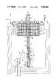
- FIG. 2is a top view schematic diagram showing a complete and preferred embodiment of a laser-activated Raman scattering, sampling and multi-channel detection system using an intracavity gas cell and collimated laser beam.
- FIG. 3ais a top section view of a gas sampling cell as utilized in the multi-channel, collicated beam system shown in FIG. 2.
- FIG. 3bis a side view of the gas cell shown in FIG. 3a.
- FIG. 3cis an end view of the gas cell in FIGS. 3a and 3b.
- FIG. 3dis a perspective view of the gas cell shown in FIGS. 3a, 3b, and 3c.
- FIG. 4is a schematic diagram showing the flow of gas into and out of the gas cell.
- FIG. 5is a cross-section view of a preferred embodiment of the detector channels shown in position adjacent the gas cell.
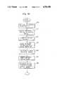
- FIG. 6is a flowchart for the main microprocessor routine for analysis of respiratory gases and anesthetic agents.
- FIG. 7ais a flowchart for the calculation procedure.
- FIG. 7bis a continuation of FIG. 7a.
- FIG. 8is a flowchart for the updating of the trend data procedure.
- FIG. 9is a flowchart for the self calibration procedure.
- FIG. 10is a flowchart for the display routine of the trend data.
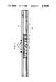
- FIG. 11is a side view of a laser resonator and gas cell configuration showing the gas cell being located outside of the resonator cavity and also indicating intracavity locations, wherein one or more gas cells could be located.
- FIGS. 11a, 11b, 11c and 11dare top view schematic diagrams of portions of the resonator shown in FIG. 11 showing how these portions can also serve as parts of an intracavity gas cell.
- FIGS. 1a and 1cillustrate block diagram schematic representations of two Raman analysis configurations which incorporate the features of the preferred embodiment of the present invention.
- FIG. 1ashows a configuration 2 which will be referred to as a collimated beam system while
- FIG. 1cshows a configuration 4 which will be referred to as a focused beam system.
- FIG. 1ashows the collimated light beam system 2 comprising a light source 10, light beam collimators 12 and 14, and multiple analysis channels 16.
- the analysis channels 16a through 16hare positioned adjacent a light beam 18.
- the light beam 18is emitted by the light source 10 along longitudinal axis 20.
- a sampling region 26 having a longitudinal axis 28 substantially coincident with the longitudinal axis 20 of the light beam 18contains a gaseous sample for analysis.
- the collimators 12 and 14are positioned about the axis 20 so that as the light beam 18 passes along the axis 20, it becomes substantially collimated; that is, it is comprised of substantially parallel rays 22, 24 which exhibit small angles of divergence from a focal point or convergence toward a focal point. (The divergence shown in FIG.
- the collicators 12 and 14may not be necessary when the light source 10 produces a low divergence light beam. This is often the case where the light source comprises a laser.
- the geometric configuration of region 26may also function to further collimate the light beam 18.
- Light scattered from the sample within region 26is detected and analyzed by analysis channels 16a through 16h.
- Channels 16are positioned adjacent to and along the longitudinal axes 20, 28 of the light beam 18 and sampling region 26, respectively.
- Analysis channels 16collect scattered light from region 26 from either side of axis 28, as illustrated by channels 16a, 16b, 16e, 16f, 16g and 16h, or from both sides as illustrated by channel 16c.
- Light scattered toward the side of the axes 28 opposite channel 16cis collected and reflected back to channel 16c by a mirror 16d.
- Mirror 16dmay be either a planar mirror or a focusing mirror.
- the light beam 18is polarized.
- the direction of polarization of the E-vectoris along the Y-axis which, in reference to FIG. 1a, is the axis perpendicular to the plane of the figure.
- the direction of propagation of light beam 18is along the Z-axis, and the detector channels are substantially aligned with the X-axis and lie in the XZ plane.
- the scattering geometry for polarized light Raman scatteringis illustrated in FIG. 1b.
- the scattering sampleis located at the origin, 30 of the XYZ coordinate system and is illuminated by polarized light 31 propagating along the Z-axis 20.
- the E-vector polarization state 32 of the polarized light 31is in the YZ-pane.
- the scattering properties of the Raman light scattered into the two orthogonal planes (planes YZ and XZ) which are parallel to the Z-axis of propagationare of particular interest in this geometry.
- Raman scattered lightconsists of isotropic and non-isotropic components.
- the resulting scattering intensity distribution in spacecan be described in terms of the invariant, a, which is a measure of the average polarizability, the anisotropy of the polarizability, ⁇ 2 , and the angle in the observation plane.
- awhich is a measure of the average polarizability, the anisotropy of the polarizability, ⁇ 2 , and the angle in the observation plane.
- awhich is a measure of the average polarizability, the anisotropy of the polarizability, ⁇ 2 , and the angle in the observation plane.
- awhich is a measure of the average polarizability, the anisotropy of the polarizability, ⁇ 2 , and the angle in the observation plane.
- awhich is a measure of the average polarizability, the anisotropy of the polarizability, ⁇ 2
- N ⁇ iis the number and f(a 2 , of modules in the initial vibrational state ⁇ i ⁇ 2 , ⁇ 2 , ⁇ ) and f(a 2 , ⁇ 2 , ⁇ 2 , ⁇ ) are functions of the invariants a 2 , ⁇ 2 , ⁇ 2 and the observation angles ⁇ and ⁇ .
- .sup. ⁇ I( ⁇ )is the Raman scatter intensity as a function of ⁇ in the XZ plane which is perpendicular to the polarization E-vector
- .sup. ⁇ I( ⁇ )is the Raman scatter intensity as a function of ⁇ in the YZ plane which is parallel to the polarization E-vector
- Equation (5)indicates that the Raman scattering intensity is isotropic in the plane perpendicular to the E-vector (XZ plane). In other words, .sup. ⁇ I( ⁇ ) is not functionally dependent upon the angle ⁇ in the XZ plane.
- the Raman scattered intensityis at a minimum, but generally non-zero, value.
- each analysis channel 16it is preferable to locate each analysis channel 16 so that it collects Raman light in the XZ plane.
- a particularly convenient direction in the XZ planeis in the direction of the X axis, which is perpendicular to the laser beam axis 20 and the electric E-vector axis 32. It will be readily apparent to one skilled in the art that there are numerous ways to achieve this desired alignment. The techniques described herein are thus meant to be illustrative but not limiting.
- plural high intensity regions 36 or focal pointsare formed along the longitudinal beam axis 20.
- the focal points 36are formed by passing beam 18 from source 10 through optical lenses 38 or other equivalent focusing means.
- the analysis channels 40are positioned to sample Raman scattered light from samples located at these high intensity regions 36.
- Analysis channelsmay be located in any position about the axis 20 as shown by channels 40a, 40d and 40e.
- Raman scattered lightmay be collected from opposing sides of the axis 20 by using a collection mirror 40c in conjunction with a channel 40b located opposite the mirror 40c.
- an array of channels 40fmay be located in an equatorial plane 42 about the axis 20 and high intensity region 36d. When using the equatorial array 40f, it may be desirable for the incident beam 18 to be unpolarized.
- a laser source 10 having the above-described characteristicsis readily available from Ion Laser Technology Corporation located in Salt Lake City, Utah as Model No 350A.
- the extra cavity power of the beam from this laser, when using a 98 percent reflectance output coupler 94,is preferably on the order of tens of milliwatts.
- a third dust-tight sleeve 121protects Brewster window 106 on gas cell 50 and end reflector 108.
- End reflector 108comprises a high relectivity mirror coated on the back side of a Littrow prism.
- end reflector 108may comprise a flat mirror with a laser line selective coating.
- the output coupler 94would also be coated with a laser line selective coating for wavelength selection.
- Brewster windows 96, 98, 102, 106 and end reflectors 94, 108 and their respective coating and/or orientationsare selected to maximize the power of the polarized selected wavelength light circulating in the resonant cavity.
- the Brewster windows 96, 98, 102, and 106are oriented to cause laser beam 78 to have a polarization vector that is substantially perpendicular to the plane of FIG. 2.
- the position of gas cell 50 and plasma tube 80are within the resonant cavity of the laser. This configuration is often referred to as intracavity. Location of the gas cell 50 within the resonant cavity increases the amount of laser power available for Raman scattering from the gas molecules in the cell chamber 104.
- the intracavity poweris higher than extracavity power by a factor of [1+R]/T, where R and T are the reflectivity and transmission, respectively of output coupler reflector 94.
- both the end reflector 108 and the output reflector 94may have a reflectivity of approximately 99.9% or greater, thus providing a substantial increase in circulating optical power and Raman scatter signals for intracavity sample placement as compared with extracavity placement.
- a beam analysis system 110comprising output coupler reflector 94, a narrow laser line filter 112, a diffuser 114, and a light detector 116.
- Filter 112is located adjacent output coupler reflector 94 and diffuser 114 is located between filter 112 and detector 116.
- Detector 116is connected via line 118 to laser power supply 86.
- Filter 112serves to reject diffuse Argon plasma glow and transmit the small amount of laser light which transmits the output coupler mirror 94.
- Stabilizationis achieved by monitoring the intensity of light beam 78 via detector 116 and adjusting the power supply 86 in response to changes in the intensity of the light beam 78, thus forming a feedback system.
- a small sample, approximately 0.1% of light beam 78is extracted from the resonant cavity via output coupler reflector 94, which is selected to have a reflectivity of approximately 99.9% or greater.
- Filter 112allows light having a wavelength of substantially 488 nanometers to pass to diffuser 114.
- Diffuser 114causes the sampled and filtered 488 nanometer light sample to be spread over a substantial portion of the sensitive region of detector 116, thus reducing effects of beam wander over the detector's sensitive region which may not be uniform.
- the output from detector 116which is a function of the sampled light beam intensity, is used to control the output from power supply 86 to the plasma discharge tube 80, thus completing the feedback loop for stabilizing the intensity of the laser beam 78.
- Gas cell 50provides a containment used for the gas sample being analyzed which enables the sample to be placed within the resonant cavity of the laser without substantially reducing the circulating optical power in the cavity. This arrangement makes efficient use of available laser output power by maximizing the number of interactions between the laser beam and the gas molecules which result in Raman scattering.
- a preferred embodiment of gas cell 50comprises a central chamber 104 and eight output channels 120 which form optical passageways between the central chamber 104 and the outside of the gas cell.
- the eight output channelsare arranged so that they are perpendicular to a longitudinal axis 121 of the chamber 104 which coincides with the axis of propagation of the laser beam 78.
- the output channels 120further have axes of symmetry located in the XZ plane of FIG. 2, which is the plane perpendicular to the E vector axis of polarization of the laser light beam 78.
- Broadband coatingsare typically formed of multilayer dielectric films, comprising alternate layers of various refractive index transparent materials, combined in such a way so as to reduce the overall reflectance to an extremely low level for the spectral range covered. Over the broadband range, the reflectance will not generally exceed 1.0% and will generally be below 0.6%.
- the gas cell 50is connected to the source of gas to be analyzed by an inlet 142.
- An outlet 144is provided for discharging the sample gas from the cell chamber 104.
- the design of the cell 50allows for a very small volume of gas, typically between about 0.1 and 1.0 cubic centimeters, to continuously flow through the laser beam 78.
- the cell 50is also well adapted for use in a batch-type operation in that only a small sample is required of any given gas to be analyzed.
- the inlet 142is connected via supply line 148 to a three-way solenoid valve 149. Sample gas is drawn into the cell interior 104 by means of an air pump 150 which is connected via a tubing line 153 to outlet 144.
- Line 151connects to a second three-way solenoid valve 160 which, when not activated allows room air to be drawn via line 161 into the cell 50 for system calibration against nitrogen and oxygen gas, or when solenoid 160 is activated a calibration gas mixture may be drawn into the cell 50 via line 157.
- a respiratory gas or other sample gasmay be drawn vial line 152 from the airway of a patient or other sample source.
- membrane filter 156becomes plugged, the gas pressure in the sample cell 50 will drop below a threshold value causing measured signals to be erroneous. In such case, the electronic barometer 158 signals the microprocessor 70 which, in turn, alerts the user or operator.
- gas cell 50can be easily removed from the intracavity space by sliding sleeve 119 along the plasma tube 80 away from gas cell 50. The cell is then slide away from sleeve 121 and lifted out of the resonant cavity. Easy removal of the gas cell 50 facilitates field service and maintenance. For example, cleaning of the end windows 102 and 106 may be required if they become contaminated by dust particulates or organic films.
- Raman scattered lightexits the gas cell 50 through windows 146 and enters the array of detector channels 60.
- the detector array 60 shown in the embodiment of FIG. 2comprises a series of eight individual detection channels on either side of gas cell 50, one channel being located to detect the light output from each of the eight output windows 146 of the gas cell 50.
- the eight detector channelsare all quite similar, therefore, for clarity, only one channel will be described in detail, it being understood that the explanation also applies to the remaining seven channels.
- the choice of eight channelsis illustrative only, it being understood that a different number of channels may be aligned on either side of the gas cell depending upon the number of gases being sampled and detected.
- the PMTis connected to a power supply 220 via path 221. Electrical pulses representative of light detected by the PMT 219 are transmitted via a line 222 to an amplifier discriminator 224 where they are processed and analyzed. the processed pulses are then transmitted to microprocessor 70 via lines 226 where they are accumulated, analyzed, stored and displayed on display 71.
- detector 219may be any suitable detector utilizing photon counting or photocurrent electronics, such as a photodiode, intensified diode array, charged coupled device or photomultiplier tube power by an appropriate power supply 220 via line 221.
- FIG. 5A more detailed cross-section view of a typical detector channel 60a is shown in FIG. 5.
- the detector 60ais positioned against the gas cell 50 so that the optical axis 230 of the detector channel 60a is perpendicular to the axis of propagation of laser beam 78 as well as being perpendicular to the direction of polarization of the E-vector of the laser beam. In FIGS. 1b and 2 this direction is along the x-axis.
- Raman scattered light from region 122 of the chamber 104is transmitted through window 146, collected and collimated by lens 214, filtered by the laser line rejection filter 216 and the Raman line bandpass filter 217 before being detected by PMT 219.
- Lens 218serves two functions. First, it collects Raman scattered light.
- Collection lens 214may actually be a series of optimally configured lens elements all of which are anti-reflection coated.
- One such exampleis a fast (f/1.2) camera lens.
- Each collection lens 214must be properly aligned with respect ot the laser beam 78, to ensure efficient collection of the scattered light from the gas cell 50.
- Elastically and inelastically-scattered light collected by lens 214 in each channel 60is directed to one or more serially-oriented high rejection laser line filter(s) 216.
- Filter(s) 216greatly attenuates the elastically-scattered laser line (Rayleigh scatter) to minimize interference with the Raman or inelastically-scattered light and transmits substantially all of the inelastically-scattered Raman lines.
- the transmitted Raman lines which arise from the incident laser beam interacting with the sample gascorrespond to the vibrational/rotational energies of the scattering molecules are then transmitted through interference filter 217.
- the Raman spectra line-specific filters 217may be different in each channel and are chosen so that instrument can detect and quantify a number of different polyatomic gas of interest. Hence, the number of channels to be utilized is dependent upon the number of gases to be identified and quantitated.
- the collimated beam embodiment of the invention illustrated in FIGS. 1a and 2collects light from a narrow rectangular-shaped area 122 within the gas cell 50.
- an ideal optical systemwould comprise a lens system having a rectangular shaped focal spot and would collimate the light collected from the chamber 104 for further propagation through filters 217 and 218.
- filters 217 and 218This is desirable because multilayer dielectric filters which are designed to reject elastically scattered laser light and transmit specific Raman lines function best when the incident light is reasonably well colimated.
- Such a special purpose lensis difficult to produce and expensive.
- one approach for implementing the collimated beam embodiment of the inventionutilizes a single plano-convex collection lens 214 to collect signals from as wide an interception angle of laser beam 78 in gas cell 50 as is possible.
- light collectionis from the rectangular-shaped region 122 of the laser beam having dimensions of about 0.5 mm in width and several millimeters in length. The result is that the lens 214 collects much more light (both elastic and inelastic) than if it were viewing a point source within the laser beam 78. Consequently, the Raman signals are much higher.
- the aperture size for the laser beam path entering and exiting the gas cell along its longitudinal axismay be determined by an iris or circular baffle (not shown) located at either or both ends of the cell 50 just inside the end windows 102 and 104.
- an iris or baffle (not shown) or series of bafflesmay be located in the channel between each side window 146 and the corresponding collection lens 214. Additional baffles (not shown) may be positioned between the collection lens 214, filters 216 and 217, and between focusing optics 218 and photodetector 219 to minimize stray light.
- intracavity aperture 100functions to reduce the collateral plasma glow contribution to the background signal.
- flat black paintmay be used to coat the interior surface of the optical collection channels 60 to further absorb stray light background.
- the collection lens 214may be replaced by a single or optimally arrayed series of fiber optics.
- Such fiber opticalsgenerally have a much higher numerical aperture than lenses and are therefore more efficient light collectors.
- any means of transmitting or redirecting the signal to the optical filter system and/or detectorsmay be utilized, i.e., refractive optics such as lenses, reflective optics such as mirrors or transmissive optics such as fiber optics.
- an analysis of the frequency components present in the Raman scattered lightprovides identification and quantification of the gases present in the scattering volume. Quantification is determined from the measure intensities of the Raman signals calibrated against reference gases and known Raman scattering cross sections.
- the narrow bandwidth interference filter 217is selected to transmit the wavelength of the Raman line for that gas. As shown in FIGS. 2 and 5, these filters are represented by a specific multilayer dielectric interference filters 217 located in each channel 60. Each specific filter 217 is chosen to pass along one or more Raman scattered lines which correspond to a discrete molecular species. A different filter is utilized for each channel, thereby making each channel specific to the detection of a different polyatomic gas species. It is possible to utilize filters which transmit more than one discrete Raman line for gas quantification. A case in point is the C-H stretch lines for the anesthetic gases with Raman frequency shifts in the region of 2900 cm -1 to 3100 cm -1 . It is also possible to utilize data from two or more channels to identify the type of anesthetic agent in use.
- the Raman scattered light having the selected frequencypasses through interference filter 217 in each channel and is input to a separate detector 219.
- Optional focusing lens 218may be used for some filters and detectors.
- the detector 219can be any device capable of receiving the optical signal, and amplifying and processing it into useful data. Represented in FIGS.
- a photomultiplier tube (PMT) 219which is connected to a signal processing unit 224 which may be a photon counter, a photocurrent amplifier or other device including a central processing unit or microprocessor which can further amplify, process and quantitate the Raman signal into useful analog or digital data which is then displayed on display device 71, e.g., a digital display, a CRT screen and/or printer.
- a signal processing unit 224which may be a photon counter, a photocurrent amplifier or other device including a central processing unit or microprocessor which can further amplify, process and quantitate the Raman signal into useful analog or digital data which is then displayed on display device 71, e.g., a digital display, a CRT screen and/or printer.
- Table Ishows that those gases of interest generally have frequency shifts substantially smaller than that for water vapor. Therefore, Raman signals from water vapor do not interfere with the Raman signals of interest since there is rarely any significant spectral overlap between the Raman signals. This is
- eight multilayer dielectric filters 217are used.
- Anesthetic agents halothane, enflurane, and isofluraneare detected by filters 217 having center wavelengths of 505.7 nm, 508.2 nm and 512.9 nm, respectively.
- Carbon dioxide, oxygen, nitrous oxide and nitrogenare quantitated by filters 217 having center wavelengths of 523.5 nm, 528.1 nm, 547.4 nm and 550.6 nm, respectively. All of the above filters have half bandwidths of approximately 1 nm.
- the anesthetic agentsare quantitated by a filter 217 having a center wavelength of 572.6 nm and half bandwidth of 10 nm. These filters are appropriate for the Raman scattering of the argon laser line at 488 nm.
- the photons received by detectors 219which are powered by power supply sources 220, are converted to electric current or voltage, amplified and sent by signal line 226 as photocurrent or photo voltage to a pulse amplifier-discriminator or current or voltage amplifier circuit 224. These signals are converted into standard digital pulses and relayed to microprocessor 70 via signal lines 226.
- the processing of the specific Raman lines entering detector 219 into useful datais accomplished by known means, and the signals entering microprocessor 70 may be processed by software to provide the desired data which are then sent to a digital or analog CRT display 71 via line 73.
- microprocessor 70The primary functions of microprocessor 70 are to accumulate, analyze, store, and display the date received from collection channels 60. Secondary functions may include routine monitoring of gas flow in the gas cell, laser intensity output, temperatures throughout the system, etc.
- the general functions of the microprocessor 70 in a preferred embodiment application for monitoring respiratory gases and anesthetic agentsare shown by the flow chart in FIG. 6.
- the softwareOn power up of the microprocessor, the software initializes the hardware, sets up the interrupt structure of the program, and sets the global variables to their starting values. It waits for the laser to come on and then displays a starting option screen that allows the user to set or change flags in global variables.
- One menu optionbegins execution of the main program. These activities are indicated in activity block 300.
- the main program softwareexecutes in an infinite loop comprising decision blocks and pathways 304, 306, 308, 310, 312, and 314. Within this loop, data is handled as it becomes available until a standby key press is detected in decision block 312 which halts execution of the program and returns control to the starting option screen displayed as part of activity block 300.
- a microprocessor timer channelprovides a 100 ms strobe to signal the system that data from collection channels 60 are ready for acceptance by the microprocessor.
- the strobegenerates an interrupt, the detector channels are read and the data are made globally available in a queue data structure, for processing as CPU time becomes available. These activities are carried out within decision block 304.
- the major operation of the calculation procedure, shown in FIG. 7ais to calculate the volume percent concentration of four gases: oxygen (O 2 ), nitrogen (N 2 ), nitrous oxide (N 2 O), and carbon dioxide (CO 2 ), as well as one of the three anesthetic vapor agents: isoflurane, halothane, or enflurane.
- Oxygen concentrationcan be calculated directly, as can the anesthetic vapor agent concentration provide that the vapor agent has previously been identified. If the vapor agent has not yet been identified or indicated, the assumption that the vapor agent is isoflurane gives approximately the correct results for enflurane and overestimates the halothane concentration by 100%, but this condition will not continue for more than 20 seconds.
- a background signal levelis subtracted from the signals representative of the oxygen, nitrogen, nitrous oxide, and carbon dioxide channels.
- activity block 324corrects the nitrogen channel for the crosstalk contribution from nitrous oxide, and then calculates the nitrogen concentration.
- the nitrous oxide crosstalk contributionis calculated from the previously determined concentration of nitrous oxide.
- the volume percent gas for nitrogen, and oxygenis determined in activity block 326 by dividing the respective channel signals by a signal representing 100% gas.
- a crosstalk value for the anesthetic vapor agent in the carbon dioxide channelis then determined in activity block 328 and subtracted from the total signal. Similarly, the crosstalk from nitrogen in the nitrous oxide channel is determined and subtracted from the total signal.
- activity block 332calculates the concentration for carbon dioxide and nitrous oxide using a method of solving n equations in n unknowns called Gaussian Elimination.
- the flow chart in FIG. 7aconnects with the flow chart in FIG. 7b.
- controlis passed from decision block 334 via control path 336 to the end of the calculation routine. If the instrument is set to identify the vapor agent, it will monitor the quantity of anesthetic vapor agent detected in the CH-stretch channel, the channel used to quantitate the anesthetics agents. Control is passed from decision block 334 via path 338 to decision block 340 wherein the concentration of the anesthetic vapor agent is compared to a threshold value.
- controlis passed via path 342 from block 340 to block 344 wherein the sums representing the signals of the various detector channels are cleared and a flag is set which indicates that no anesthetic vapor agent was identified. Control then passes via path 346 to the end of the calculation procedures.
- controlis passed via path 348 to activity block 350 wherein the signals from the three anesthetic filter channels and from the nitrous oxide channel as well as the CH-stretch channel are integrated for a total of 10 seconds.
- Controlis passed from activity block 350 via path 352 to decision block 354 wherein the duration of the integration time is checked. If the integration time is not sufficient, control passes via path 356 to the end of the calculation procedure. If the integration time is sufficient, control passes from decision block 354 via path 358 to activity block 360 wherein the data are averaged and background is subtracted.
- controlpasses via path 362 to activity block 364 wherein the data are processed as five equations in four unknowns and the solution is again arrived at using the Gaussian Elimination technique.
- the concentrations of the vapor agents determined in activity block 364are transferred via path 366 to decision block 368. If none of the concentrations of the anesthetic vapor agents are greater than a threshold, then control is transferred via path 370 to the end of the calculation routine. If any of the concentrations of the anesthetic vapor agents are greater than the thresholds, then control is transferred via path 372 to decision block 374. If more than one of the anesthetic vapor agents have concentrations greater than the threshold, then control is transferred via path 376 to activity block 378 wherein an alarm is sounded indicating that multiple vapor agents are present. Control then proceeds via path 380 to activity block 384.
- controlis passed via path 382 to activity block 384 wherein an identification flag is set to indicate which anesthetic vapor agent is present in the highest concentration. Control then proceeds via path 386 to activity block 388 wherein the display screen is updated with the identity of the identified vapor agents. Control then passes via path 390 to the end of the calculation routine and proceeds with activity block 392 of the flow chart for the main routine in FIG. 6.
- the CO 2 concentration datais filtered using a low pass running average digital filter. Control then passes via path 394 to decision block 396 wherein if the display mode of the instrument is set to show a waveform, control passes via path 398 to decision block 400 which paints the new concentration data point on the display screen. Control then passes via path 402 to activity block 408. If, in decision block 396, the display mode is not enabled, control passes via path 406 to activity block 408 wherein tests are performed to determine whether the patient is exhaling or inhaling. This determination is made by observing whether the carbon dioxide concentration is above a threshold value, which is an indication of expiration. This information is signalled to the rest of the program with a global flag.
- the number of data strobes between breath detectionsis measured to supply a respiration rate value. All data are passed via path 410 to decision block 412 wherein all data are compared against upper and lower warning limits as set by the user, and if any concentrations are above the upper warning limits or below the lower warning limits an alarm condition is noted on the display. After checking the warning limits, control passes via path 414 to activity block 416 wherein a procedure which updates the digital data on the screen is executed. A detailed flow chart for this procedure is shown in FIG. 8.
- Decision block 417determines if expiration is occurring. If expiration is occurring, control passes via path 418 to activity block 420 wherein the current expiration data is added to the expiration data sums. Control then passes via path 422 to decision block 424. If expiration is not occurring at decision block 417, then control is transferred via path 425 to activity block 427 wherein the current data is added to the inspiration sums. Control is then passed via path 429 to decision block 424. If it is time to update the screen for a particular gas, which occurs once every nine seconds, control is passed from decision block 424 via path 426 to decision block 428.
- the main programproceeds via path 442 to activity block 444 which performs a self-calibration procedure.
- activity block 444which performs a self-calibration procedure.
- the detailed flow chart of the self-calibration procedureis presented in FIG. 9. Entering the self-calibration routine via path 442 into activity block 445 wherein the current message is cleared and a calibration message is written. Control then passes to activity block 446 which connects a sample calibration port to the instrument. Proceeding to activity block 448, factory calibration data is read in from memory. In activity block 450, data is taken from a room air sample.
- the instrumentis switched to an argon sampling port in activity block 452 wherein an on-board argon tank supplies argon gas to the sampling port of the instrument.
- the argon gasis used in activity block 454 to obtain a background.
- the sampling port pressuresare tested for consistent values.
- the concentration of oxygen and nitrogen in the room air sampleis fixed, so any change in the signals for oxygen and nitrogen as compared to their factory calibration values in activity block 458, causes an analogous change in the signals in the other channels.
- the oxygen and nitrogen signalsare ratioed to their factory calibration values and this ratio is used to modify the calibration coefficients for all of the other gases.
- the sampling portis then switched to the patient port in activity block 462.
- the systemrestores its status by clearing the calibrate message and returning to the main routine along control path 466.
- controlis passed via line 466 to the decision block 308. If the system is ready to paint digital data on the display screen, control passes vial line 468 to activity block 470, which updates the digital information on the screen.
- a detailed flow chart of the paint screen software when displaying trend datais shown in FIG. 10.
- the softwaredraws the correct display and then proceeds via path 472 to activity block 474, wherein the trend data is extracted from the trend buffer. Control then passes via path 476 to activity block 478 wherein the data is added to the sums representing the expired and inspired values. Continuing via path 480 to decision block 482, if the end of the trend data has not been reached, control continues along path 484 to decision block 486. If it is not time to average the data, then control passes via line 488 back to activity block 474. The steps beginning with activity block 474 through decision block 486 continue until it is time to average the data, at which time control passes via path 490 to activity block 492 wherein the data are averaged.
- Controlagain passes via path 488 to activity block 474 and continues through decision block 482 until such time as the end of the trend buffer is reached. When this occurs, control transfers via path 494 to activity block 496 wherein the correct concentration scale is selected and displayed. Control then passes via path 498 to activity block 500 wherein the data for expired and inspired trend as a function of time are displayed in the plot window. Transfer then occurs via path 502 back to the main routine to decision block 312.
- controlis transferred directly via path 310 to activity block 312.
- the keypadis read to see if any instructions have been received from the user to change the mode. If a key press has been received, control passes via path 504 to activity block 506 wherein the key press is parsed by comparing it to a list of mode change instructions for each key. These instructions primarily involve only the setting of global flags and redrawing the display. Control then returns via line 314 back to the starting decision block 304 of the main program infinite loop.
- a second membrane filter housing 155 and filter 156 upstream of the solenoid 149, gas cell 50 and pump 150serves as additional protection against end window contamination.
- a second electronic barometer(not shown) may be conveniently located within the system to sense changes in atmospheric pressure necessary to accurately calculate the concentration of any gas in the sample in terms of millimeters of Hg.
- FIG. 11illustrates an expansion of this approach utilizing Brewster windows and resonator mirrors to define the ends of the gas cell and contain the gas sample within the resonator cavity.
- FIG. 11broadly shows a laser 10, radiator 92, cathode 82, anode 84 and plasma tube 80 similar to those defined in FIG. 2.
- the intracavity laser beamis again indicated by numeral 78.
- Two intracavity cells, one on either side of plasma tube 80are defined.
- the first cellis to the left of the plasma tube 80 being defined by mirror 94 and Brewster window 96.
- sleeves 560 and 562may contain side windows (not shown) in the same manner as gas cell 50 shown in FIG. 3.
- two additional windows 564 and 566have been included within the left and right gas cells defined on either side of the plasma tube 80.
- the presence of these two end windows 564 and 566effectively splits the resonating cavity of the laser into four intracavity gas cells which may be adapted for use in a manner similar to cell 50 shown in FIG. 2. Each of these four cells is illustrated in more detail in FIGS. 11a-11d.
- FIG. 11ais a partial top section view of a portion 50a of FIG. 11 between mirror 94 and window 564.
- Sleeve 560has been modified to contain side windows 146a through which the inelastic-scattered Raman light and Rayleigh scattered elastic laser light may be transmitted to optical filter-detector channels 60 in the same manner as previously described in conjuction with FIGS. 2, 3, and 5.
- the cell 50ais defined by mirror 94, end window 564 and housing 560 (modified sleeve) containing side windows 146.
- Adjacent mirror 94 and end window 564are baffles 570 and 572 which serve to minimize scattered light from mirror 94 and end window 564 from entering the actual optical collection area.
- FIG. 11cis a partial top section view of a portion of FIG. 11c between Brewster window 98 of plasma tube 80 and end window 566.
- Sleeve 562has been modified to contain side windows 146c as described in conjuction with FIG. 119a.
- the cell 50cis defined by Brewster window 98, end window 566 and housing 562 (modified sleeve) containing side windows 146c.
- Adjacent Brewster window 98 and end window 566are baffles 578 and 580 which serve to minimize scattered light from Brewster window 98 and end window 566 from entering the actual optical collection area.
- FIG. 11dis a partial top section view of a portion of FIG. 11 between window 566 and end mirror 108.
- Sleeve 562has been modified to contain side windows 146d as described in conjuction with FIG. 11a.
- the cell 50dis defined by end window 566, end mirror 108 and housing 562 (modified sleeve) containing side windows 146d.
- Adjacent end window 566 and end mirror 108are baffles 582 and 584 which serve to minimize scattered light from end window 566 and end mirror 108 from entering the actual optical collection area.
- FIG. 11also shows that a gas cell 50e, similar to that disclosed in FIG. 3, may be utilized in the extracavity mode outside the laser resonator.
- This cell 50eas shown in the extracavity position in FIG. 11, consists of a housing 586, end windows 602 and 604 and side windows 164e which serve the same functions as described in FIGS. 1-3.
- extracavity beam 600has to have sufficient optical power to generate detectable Raman scattered signals.
- End windows 602 and 604confine the gas within the gas cell 50e and enable the extracavity beam to propagate through the cell 50e.
- Windows 602 and 604are coated with a highly efficient narrowband anti-reflection coating, i.e., a "V" coating, for the particular wavelength of the laser.
- V-coatingare multilayer dielectric anti-refelection coatings which reduce the reflectance of an optical component to rear-zero for one very narrow wavelength range, and are generally intended for use at normal or near-normal incidence.
- windows 602 and 604are parallel to each other and substantially normal to the axis of the housing 586 and the laser beam 600.
- Such coatingswill achieve maximum reflectances of not more than about 0.25% and are generally effective to allow only about 0.1% reflectance per surface at the specified wavelength. Thus, they do not appreciably interfere with the transmission of the laser beam through the resonating cavity of the laser.
- the end windows 602 and 604may be uncoated fused silica oriented at Brewster's angle.
- the system and process described hereinwere developed primarily for monitoring respiratory and anesthetic agent gases. However, it may also be useful for monitoring blood and tissue gases (in conjuction with a suitable sampling catheter), gases used for lung function and cardiac output determinations and hazardous gases in the workplace, and for detecting leaks in chemical process plants, monitoring levels of suspected chemical and environmental pollutants and in other applications where polyatomic gaseous molecules are to be detected and measured.
Landscapes
- Physics & Mathematics (AREA)
- Spectroscopy & Molecular Physics (AREA)
- General Physics & Mathematics (AREA)
- Health & Medical Sciences (AREA)
- Nuclear Medicine, Radiotherapy & Molecular Imaging (AREA)
- Life Sciences & Earth Sciences (AREA)
- Chemical & Material Sciences (AREA)
- Analytical Chemistry (AREA)
- Biochemistry (AREA)
- General Health & Medical Sciences (AREA)
- Immunology (AREA)
- Pathology (AREA)
- Investigating, Analyzing Materials By Fluorescence Or Luminescence (AREA)
- Spectrometry And Color Measurement (AREA)
Abstract
Description
.sup.⊥ I(φ)=.sup.⊥ I.sub.∥ (φ)+.sup.⊥ I.sub.⊥ (φ) (3)
.sup.∥ I(θ)=.sup.∥ I.sub.∥ (θ)+.sup.∥ I.sub.⊥ (θ) (4)
TABLE I ______________________________________ Frequencv Shift and Normalized Relative Scattering Cross Section for Several Respiratory and Anesthetic Gases Frequency Relative Scattering Gas Species Shift (CM.sup.-1) Cross Section ______________________________________ N.sub.2 2331 1.0 O.sub.2 1555 1.0 CO.sub.2 2143 0.9 CO 1285 0.8 1388 1.2 N.sub.2 O 1285 1.8 2224 0.5 H.sub.2 O 3652 2.8 Isoflurane 995 -- Enflurane 815 -- Halothane 717 -- ______________________________________
Claims (57)
Priority Applications (9)
| Application Number | Priority Date | Filing Date | Title |
|---|---|---|---|
| US07/106,791US4784486A (en) | 1987-10-06 | 1987-10-06 | Multi-channel molecular gas analysis by laser-activated Raman light scattering |
| JP63508695AJPH0786462B2 (en) | 1987-10-06 | 1988-09-28 | Multichannel molecular gas analysis by laser-triggered Raman light scattering |
| AU26078/88AAU612732B2 (en) | 1987-10-06 | 1988-09-28 | Multi-channel molecular gas analysis by raman light scattering |
| DE3885104TDE3885104T2 (en) | 1987-10-06 | 1988-09-28 | MULTI-CHANNEL DEVICE FOR ANALYZING MOLECULAR GAS USING LASER-EXCITED RAMAN LIGHT SCATTERING. |
| KR1019890701038AKR950014941B1 (en) | 1987-10-06 | 1988-09-28 | Multi-channel molecular gas analysis by laser-activated raman light scattering |
| EP88909416AEP0380580B1 (en) | 1987-10-06 | 1988-09-28 | Multi-channel molecular gas analysis by laser-activated raman light scattering |
| AT88909416TATE96227T1 (en) | 1987-10-06 | 1988-09-28 | MULTICHANNEL DEVICE FOR ANALYZING MOLECULAR GASES USING LASER EXCITED RAMAN LIGHT SCATTERING. |
| PCT/US1988/003394WO1989003515A1 (en) | 1987-10-06 | 1988-09-28 | Multi-channel molecular gas analysis by laser-activated raman light scattering |
| CA000579233ACA1323205C (en) | 1987-10-06 | 1988-10-04 | Multi-channel molecular gas analysis by laser-activated raman light scattering |
Applications Claiming Priority (1)
| Application Number | Priority Date | Filing Date | Title |
|---|---|---|---|
| US07/106,791US4784486A (en) | 1987-10-06 | 1987-10-06 | Multi-channel molecular gas analysis by laser-activated Raman light scattering |
Publications (1)
| Publication Number | Publication Date |
|---|---|
| US4784486Atrue US4784486A (en) | 1988-11-15 |
Family
ID=22313267
Family Applications (1)
| Application Number | Title | Priority Date | Filing Date |
|---|---|---|---|
| US07/106,791Expired - LifetimeUS4784486A (en) | 1987-10-06 | 1987-10-06 | Multi-channel molecular gas analysis by laser-activated Raman light scattering |
Country Status (8)
| Country | Link |
|---|---|
| US (1) | US4784486A (en) |
| EP (1) | EP0380580B1 (en) |
| JP (1) | JPH0786462B2 (en) |
| KR (1) | KR950014941B1 (en) |
| AU (1) | AU612732B2 (en) |
| CA (1) | CA1323205C (en) |
| DE (1) | DE3885104T2 (en) |
| WO (1) | WO1989003515A1 (en) |
Cited By (121)
| Publication number | Priority date | Publication date | Assignee | Title |
|---|---|---|---|---|
| US4953976A (en)* | 1989-03-20 | 1990-09-04 | Spectral Sciences, Inc. | Gas species monitor system |
| US4979123A (en)* | 1987-05-30 | 1990-12-18 | Goldstar Co., Ltd. | Apparatus for determining concentrations of mineral elements |
| WO1991018277A1 (en)* | 1990-05-11 | 1991-11-28 | Albion Instruments | Gas analysis system having buffer gas inputs to protect associated optical elements |
| US5135304A (en)* | 1990-05-11 | 1992-08-04 | Boc Health Care, Inc. | Gas analysis system having buffer gas inputs to protect associated optical elements |
| EP0557658A1 (en)* | 1992-02-24 | 1993-09-01 | Hewlett-Packard Company | Raman spectroscopy of respiratory gases |
| US5245405A (en)* | 1990-05-11 | 1993-09-14 | Boc Health Care, Inc. | Constant pressure gas cell |
| US5315614A (en)* | 1993-05-03 | 1994-05-24 | The Spectranetics Corporation | Apparatus and method for soft focusing energy into an optical fiber array |
| EP0600711A3 (en)* | 1992-12-03 | 1994-06-29 | Hewlett Packard Co | Method for calibrating a spectrograph for gaseous substances. |
| JPH06323995A (en)* | 1993-03-29 | 1994-11-25 | Albion Instr Inc | Method and equipment for performing zero calibration of raman spectroscopic analysis device |
| US5404218A (en)* | 1993-11-18 | 1995-04-04 | The United States Of America As Represented By The United States Department Of Energy | Fiber optic probe for light scattering measurements |
| US5408314A (en)* | 1993-02-24 | 1995-04-18 | Perry; Jeffrey | Dark current subtraction with abbreviated reference cycles and recursive filtering |
| US5506678A (en)* | 1992-02-24 | 1996-04-09 | Hewlett Packard Company | System for collecting weakly scattered electromagnetic radiation |
| EP0708323A2 (en) | 1994-10-17 | 1996-04-24 | Albion Instruments Inc. | Diode laser pumped raman gas analysis system with reflective hollow tube gas cell |
| US5533512A (en)* | 1994-03-18 | 1996-07-09 | Ohmeda Inc. | Method and apparatus for detection of venous air emboli |
| US5596404A (en)* | 1994-12-30 | 1997-01-21 | Albion Instruments, Inc. | Raman gas analysis system with flexible web and differential thread for precision optical alignment |
| US5673109A (en)* | 1996-07-10 | 1997-09-30 | Ohmeda Inc. | System and method for increasing the efficiency of a raman gas analysis system |
| US5703683A (en)* | 1996-05-28 | 1997-12-30 | Ohmeda Inc. | Extruded wobble plate optical alignment device |
| US5754288A (en)* | 1995-08-09 | 1998-05-19 | Kyoto Dai-Ichi Kagaku Co., Ltd. | Optical measuring method of expiration components |
| EP0814333A3 (en)* | 1996-06-18 | 1998-09-16 | Ohmeda Inc. | Raman gas analyzer |
| US5870188A (en)* | 1995-09-20 | 1999-02-09 | Kyoto Dei-Ichi, Kagaku Co. Ltd. | Measuring method and measuring apparatus by light scattering |
| EP0947825A1 (en)* | 1998-04-21 | 1999-10-06 | Hewlett-Packard Company | Noble gas detection and determination |
| US6046453A (en)* | 1998-03-13 | 2000-04-04 | Datex-Ohmeda, Inc. | Agent identification for anesthetic gas monitors using minimum alveolar concentration (MAC) values |
| US6072577A (en)* | 1998-04-21 | 2000-06-06 | Hewlett-Packard Company | Noble gas detection and determination |
| US6124134A (en)* | 1993-06-25 | 2000-09-26 | Stark; Edward W. | Glucose related measurement method and apparatus |
| WO2001015762A1 (en)* | 1999-08-28 | 2001-03-08 | Philips Corporate Intellectual Property Gmbh | Avoidance of poisoning effects during anesthesia |
| US20020029003A1 (en)* | 1996-07-15 | 2002-03-07 | Mace Leslie E. | Multiple function airway adapter |
| US20030082501A1 (en)* | 2001-10-25 | 2003-05-01 | Deepak Varshneya | System and method for detecting optical element contamination in a laser detector channel used in combat training |
| US6618144B1 (en)* | 1999-10-15 | 2003-09-09 | The Administrators Of The Tulane Educational Fund | Device and method of simultaneously measuring the light scattering from multiple liquid samples containing polymers and/or colloids |
| US20030190262A1 (en)* | 2001-01-24 | 2003-10-09 | Blazewicz Perry R. | Oxygen monitoring apparatus and methods of using the apparatus |
| US20040013570A1 (en)* | 1998-08-04 | 2004-01-22 | Labuda Lawrence L. | Oxygen monitoring apparatus |
| US6710878B1 (en) | 1999-06-14 | 2004-03-23 | General Electric Company | In-line particulate detector |
| US20050287041A1 (en)* | 2003-01-15 | 2005-12-29 | Martin Hahs E G | Gas cell |
| US20060263024A1 (en)* | 2005-05-20 | 2006-11-23 | Liang Dong | Single mode propagation in fibers and rods with large leakage channels |
| EP1734359A1 (en)* | 2005-06-18 | 2006-12-20 | Roche Diagnostics GmbH | RAMAN spectroscopic analysis method and system therefor |
| US20070100250A1 (en)* | 2003-02-14 | 2007-05-03 | The Charlotte-Mecklenburg Hospital Authority | Device and method for collection of exhaled alveolar breath condensate |
| US20070176685A1 (en)* | 2003-07-02 | 2007-08-02 | Arlen Barksdale | Extremely low noise V-band amplifier |
| US20070203424A1 (en)* | 2002-12-20 | 2007-08-30 | The Charlotte-Mecklenburg Hospital Authority | Disposable hand-held device for collection of exhaled breath condensate |
| WO2008020344A1 (en)* | 2006-08-18 | 2008-02-21 | Primus Special Projects (Pty) Ltd | A light detecting module for a sorter |
| US20080056656A1 (en)* | 2004-01-16 | 2008-03-06 | Liang Dong | Large core holey fibers |
| US20080180661A1 (en)* | 2007-01-29 | 2008-07-31 | Brown Gordon C | Chemical analyzer for industrial process control |
| WO2007130923A3 (en)* | 2006-05-01 | 2008-08-28 | Cellerant Therapeutics Inc | Portable platform cytometric system with isolation chamber |
| US20090097020A1 (en)* | 2004-06-30 | 2009-04-16 | Chemlmage Corporation | Multipoint method for identifying hazardous agents |
| US20090122308A1 (en)* | 2004-12-30 | 2009-05-14 | Liang Dong | Photonic bandgap fibers |
| US20090141271A1 (en)* | 2005-11-25 | 2009-06-04 | Pavel Matousek | Security Screening Using Raman Analysis |
| US20100053606A1 (en)* | 2006-11-24 | 2010-03-04 | The Science and Technology Facilities Council Harwell Innovation Campus Rutherford Appleton | Raman detection of container contents |
| US20100157418A1 (en)* | 2007-09-26 | 2010-06-24 | Imra America, Inc. | Glass large-core optical fibers |
| US7875047B2 (en) | 2002-04-19 | 2011-01-25 | Pelikan Technologies, Inc. | Method and apparatus for a multi-use body fluid sampling device with sterility barrier release |
| US7892183B2 (en) | 2002-04-19 | 2011-02-22 | Pelikan Technologies, Inc. | Method and apparatus for body fluid sampling and analyte sensing |
| US7901365B2 (en) | 2002-04-19 | 2011-03-08 | Pelikan Technologies, Inc. | Method and apparatus for penetrating tissue |
| US7909774B2 (en) | 2002-04-19 | 2011-03-22 | Pelikan Technologies, Inc. | Method and apparatus for penetrating tissue |
| US7909775B2 (en) | 2001-06-12 | 2011-03-22 | Pelikan Technologies, Inc. | Method and apparatus for lancet launching device integrated onto a blood-sampling cartridge |
| US7909777B2 (en) | 2002-04-19 | 2011-03-22 | Pelikan Technologies, Inc | Method and apparatus for penetrating tissue |
| US7909778B2 (en) | 2002-04-19 | 2011-03-22 | Pelikan Technologies, Inc. | Method and apparatus for penetrating tissue |
| US7914465B2 (en) | 2002-04-19 | 2011-03-29 | Pelikan Technologies, Inc. | Method and apparatus for penetrating tissue |
| US7919325B2 (en) | 2004-05-24 | 2011-04-05 | Authentix, Inc. | Method and apparatus for monitoring liquid for the presence of an additive |
| US20110108711A1 (en)* | 2007-10-25 | 2011-05-12 | Andriy Tsupryk | Single photon spectrometer |
| US7976476B2 (en) | 2002-04-19 | 2011-07-12 | Pelikan Technologies, Inc. | Device and method for variable speed lancet |
| US7981056B2 (en) | 2002-04-19 | 2011-07-19 | Pelikan Technologies, Inc. | Methods and apparatus for lancet actuation |
| US7981055B2 (en) | 2001-06-12 | 2011-07-19 | Pelikan Technologies, Inc. | Tissue penetration device |
| US7988645B2 (en) | 2001-06-12 | 2011-08-02 | Pelikan Technologies, Inc. | Self optimizing lancing device with adaptation means to temporal variations in cutaneous properties |
| US8007446B2 (en) | 2002-04-19 | 2011-08-30 | Pelikan Technologies, Inc. | Method and apparatus for penetrating tissue |
| US8062231B2 (en) | 2002-04-19 | 2011-11-22 | Pelikan Technologies, Inc. | Method and apparatus for penetrating tissue |
| US8079960B2 (en) | 2002-04-19 | 2011-12-20 | Pelikan Technologies, Inc. | Methods and apparatus for lancet actuation |
| US20120062884A1 (en)* | 2010-09-14 | 2012-03-15 | Seiko Epson Corporation | Detection apparatus |
| US8174691B1 (en)* | 2007-03-15 | 2012-05-08 | Arkansas State University—Jonesboro | Detection of a component of interest with an ultraviolet laser and method of using the same |
| US8197421B2 (en) | 2002-04-19 | 2012-06-12 | Pelikan Technologies, Inc. | Method and apparatus for penetrating tissue |
| US8221334B2 (en) | 2002-04-19 | 2012-07-17 | Sanofi-Aventis Deutschland Gmbh | Method and apparatus for penetrating tissue |
| US8251921B2 (en) | 2003-06-06 | 2012-08-28 | Sanofi-Aventis Deutschland Gmbh | Method and apparatus for body fluid sampling and analyte sensing |
| US8262614B2 (en) | 2003-05-30 | 2012-09-11 | Pelikan Technologies, Inc. | Method and apparatus for fluid injection |
| US8267870B2 (en) | 2002-04-19 | 2012-09-18 | Sanofi-Aventis Deutschland Gmbh | Method and apparatus for body fluid sampling with hybrid actuation |
| US8282576B2 (en) | 2003-09-29 | 2012-10-09 | Sanofi-Aventis Deutschland Gmbh | Method and apparatus for an improved sample capture device |
| US8296918B2 (en) | 2003-12-31 | 2012-10-30 | Sanofi-Aventis Deutschland Gmbh | Method of manufacturing a fluid sampling device with improved analyte detecting member configuration |
| US8333710B2 (en) | 2002-04-19 | 2012-12-18 | Sanofi-Aventis Deutschland Gmbh | Tissue penetration device |
| US8360992B2 (en) | 2002-04-19 | 2013-01-29 | Sanofi-Aventis Deutschland Gmbh | Method and apparatus for penetrating tissue |
| CN102914530A (en)* | 2011-08-05 | 2013-02-06 | 中国石油化工集团公司 | Raman spectrum gas detection system as well as detection method and application thereof |
| US8372016B2 (en) | 2002-04-19 | 2013-02-12 | Sanofi-Aventis Deutschland Gmbh | Method and apparatus for body fluid sampling and analyte sensing |
| US8382682B2 (en) | 2002-04-19 | 2013-02-26 | Sanofi-Aventis Deutschland Gmbh | Method and apparatus for penetrating tissue |
| US8435190B2 (en) | 2002-04-19 | 2013-05-07 | Sanofi-Aventis Deutschland Gmbh | Method and apparatus for penetrating tissue |
| US8439872B2 (en) | 1998-03-30 | 2013-05-14 | Sanofi-Aventis Deutschland Gmbh | Apparatus and method for penetration with shaft having a sensor for sensing penetration depth |
| US8556829B2 (en) | 2002-04-19 | 2013-10-15 | Sanofi-Aventis Deutschland Gmbh | Method and apparatus for penetrating tissue |
| US8574895B2 (en) | 2002-12-30 | 2013-11-05 | Sanofi-Aventis Deutschland Gmbh | Method and apparatus using optical techniques to measure analyte levels |
| EP2660584A2 (en)* | 2012-04-30 | 2013-11-06 | Finesse Solutions, Inc. | Method and apparatus for quantifying solutions comprised of multiple analytes |
| US8599373B1 (en) | 2011-07-07 | 2013-12-03 | University Of South Florida | Microcavity Raman sensor and method of use |
| US8641644B2 (en) | 2000-11-21 | 2014-02-04 | Sanofi-Aventis Deutschland Gmbh | Blood testing apparatus having a rotatable cartridge with multiple lancing elements and testing means |
| US8652831B2 (en) | 2004-12-30 | 2014-02-18 | Sanofi-Aventis Deutschland Gmbh | Method and apparatus for analyte measurement test time |
| US8668656B2 (en) | 2003-12-31 | 2014-03-11 | Sanofi-Aventis Deutschland Gmbh | Method and apparatus for improving fluidic flow and sample capture |
| US8702624B2 (en) | 2006-09-29 | 2014-04-22 | Sanofi-Aventis Deutschland Gmbh | Analyte measurement device with a single shot actuator |
| US8721671B2 (en) | 2001-06-12 | 2014-05-13 | Sanofi-Aventis Deutschland Gmbh | Electric lancet actuator |
| US8736835B2 (en) | 2011-07-07 | 2014-05-27 | University Of South Florida | Dual-gas microcavity Raman sensor and method of use |
| US8784335B2 (en) | 2002-04-19 | 2014-07-22 | Sanofi-Aventis Deutschland Gmbh | Body fluid sampling device with a capacitive sensor |
| US8828203B2 (en) | 2004-05-20 | 2014-09-09 | Sanofi-Aventis Deutschland Gmbh | Printable hydrogels for biosensors |
| CN104267018A (en)* | 2014-10-27 | 2015-01-07 | 武汉四方光电科技有限公司 | Method for processing gas concentration signal in Raman gas analyzer |
| US8965476B2 (en) | 2010-04-16 | 2015-02-24 | Sanofi-Aventis Deutschland Gmbh | Tissue penetration device |
| US20150106030A1 (en)* | 2012-06-14 | 2015-04-16 | Nanjing Tuozhu Pharmaceutical & Tech Co., Ltd | Endotoxin detection systems and detection methods thereof |
| US9144401B2 (en) | 2003-06-11 | 2015-09-29 | Sanofi-Aventis Deutschland Gmbh | Low pain penetrating member |
| US9226699B2 (en) | 2002-04-19 | 2016-01-05 | Sanofi-Aventis Deutschland Gmbh | Body fluid sampling module with a continuous compression tissue interface surface |
| US9248267B2 (en) | 2002-04-19 | 2016-02-02 | Sanofi-Aventis Deustchland Gmbh | Tissue penetration device |
| US9314194B2 (en) | 2002-04-19 | 2016-04-19 | Sanofi-Aventis Deutschland Gmbh | Tissue penetration device |
| US9351680B2 (en) | 2003-10-14 | 2016-05-31 | Sanofi-Aventis Deutschland Gmbh | Method and apparatus for a variable user interface |
| US9375169B2 (en) | 2009-01-30 | 2016-06-28 | Sanofi-Aventis Deutschland Gmbh | Cam drive for managing disposable penetrating member actions with a single motor and motor and control system |
| US9386944B2 (en) | 2008-04-11 | 2016-07-12 | Sanofi-Aventis Deutschland Gmbh | Method and apparatus for analyte detecting device |
| US9427532B2 (en) | 2001-06-12 | 2016-08-30 | Sanofi-Aventis Deutschland Gmbh | Tissue penetration device |
| WO2016168501A1 (en)* | 2015-04-16 | 2016-10-20 | Hunter Boyd V | Differential excitation raman spectroscopy |
| US9775553B2 (en) | 2004-06-03 | 2017-10-03 | Sanofi-Aventis Deutschland Gmbh | Method and apparatus for a fluid sampling device |
| US9795747B2 (en) | 2010-06-02 | 2017-10-24 | Sanofi-Aventis Deutschland Gmbh | Methods and apparatus for lancet actuation |
| US9820684B2 (en) | 2004-06-03 | 2017-11-21 | Sanofi-Aventis Deutschland Gmbh | Method and apparatus for a fluid sampling device |
| CN108535192A (en)* | 2018-06-15 | 2018-09-14 | 上海理工大学 | LR laser raman gas-detecting device based on Multi-path proportional detection |
| US10401296B1 (en) | 2015-04-13 | 2019-09-03 | University Of South Florida | Horizontally-scalable microcavity-enhanced raman scattering integrated platform for multigas chemical analysis |
| DE102019104481A1 (en)* | 2019-02-21 | 2020-08-27 | Laser-Laboratorium Göttingen e.V. | Method and device for the identification of volatile substances with resonator-enhanced Raman spectroscopy at reduced pressure |
| WO2020239814A1 (en)* | 2019-05-28 | 2020-12-03 | Fraunhofer-Gesellschaft zur Förderung der angewandten Forschung e. V. | Method, device and system for detecting raman scattered light |
| US10921246B2 (en) | 2019-04-03 | 2021-02-16 | Picomole Inc. | Method of tuning a resonant cavity, and cavity ring-down spectroscopy system |
| US10925515B2 (en) | 2014-05-22 | 2021-02-23 | Picomole Inc. | Alveolar breath collection apparatus |
| CN112630152A (en)* | 2020-12-18 | 2021-04-09 | 中国科学院广州能源研究所 | System for on-line measuring methane content in marsh gas pipeline |
| US11018470B2 (en) | 2017-03-13 | 2021-05-25 | Picomole Inc. | System for optimizing laser beam |
| US11262284B2 (en)* | 2019-01-24 | 2022-03-01 | Rion Co., Ltd. | Particle counter |
| CN114923863A (en)* | 2022-05-26 | 2022-08-19 | 深圳市诺安智能股份有限公司 | Detection chamber with hollow thin tube for detecting substance components |
| DE102021107229A1 (en) | 2021-03-23 | 2022-09-29 | Robert Bosch Gesellschaft mit beschränkter Haftung | Online or in-situ measuring device for measuring the concentration of a gas |
| DE102014202595B4 (en) | 2014-02-13 | 2023-06-07 | Robert Bosch Gmbh | Method and device for determining oxygen in a closed container |
| US11782049B2 (en) | 2020-02-28 | 2023-10-10 | Picomole Inc. | Apparatus and method for collecting a breath sample using a container with controllable volume |
| US11957450B2 (en) | 2020-02-28 | 2024-04-16 | Picomole Inc. | Apparatus and method for collecting a breath sample using an air circulation system |
| WO2025091108A1 (en)* | 2023-10-30 | 2025-05-08 | Summit Nanotech Corporation | System, device, and method for raman analysis of fluid samples |
Families Citing this family (3)
| Publication number | Priority date | Publication date | Assignee | Title |
|---|---|---|---|---|
| US20040142484A1 (en) | 2002-09-30 | 2004-07-22 | Intel Corporation | Spectroscopic analysis system and method |
| JP5537174B2 (en)* | 2010-01-29 | 2014-07-02 | 株式会社四国総合研究所 | Gas concentration measuring device |
| US9645077B2 (en)* | 2014-07-14 | 2017-05-09 | Lawrence Livermore National Security, Llc | Spectroscopic quantification of extremely rare molecular species in the presence of interfering optical absorption |
Citations (7)
| Publication number | Priority date | Publication date | Assignee | Title |
|---|---|---|---|---|
| US3704951A (en)* | 1969-06-11 | 1972-12-05 | Cary Instruments | S light cell for increasing the intensity level of raman light emission from a sample |
| US3723007A (en)* | 1971-01-22 | 1973-03-27 | Avco Corp | Remote quantitative analysis of materials |
| DE2723939A1 (en)* | 1977-05-24 | 1978-12-07 | Albrecht Hans Joerg | Respiratory air analyser - with scattered light detectors around multipass laser array with concave coaxial mirrors |
| US4410271A (en)* | 1981-06-15 | 1983-10-18 | Matthews Thomas G | Multiple-reflection optical gas cell |
| US4630923A (en)* | 1985-02-04 | 1986-12-23 | The United States Of America As Represented By The United States Department Of Energy | Fiberoptic spectrophotometer |
| US4648714A (en)* | 1985-09-11 | 1987-03-10 | University Of Utah | Molecular gas analysis by Raman scattering in intracavity laser configuration |
| US4676639A (en)* | 1986-01-22 | 1987-06-30 | Biomaterials International, Inc. | Gas cell for raman scattering analysis by laser means |
Family Cites Families (1)
| Publication number | Priority date | Publication date | Assignee | Title |
|---|---|---|---|---|
| US3807862A (en)* | 1972-12-18 | 1974-04-30 | Sybron Corp | Raman spectroscopy in the presence of fluorescence |
- 1987
- 1987-10-06USUS07/106,791patent/US4784486A/ennot_activeExpired - Lifetime
- 1988
- 1988-09-28EPEP88909416Apatent/EP0380580B1/ennot_activeExpired - Lifetime
- 1988-09-28WOPCT/US1988/003394patent/WO1989003515A1/enactiveIP Right Grant
- 1988-09-28KRKR1019890701038Apatent/KR950014941B1/ennot_activeExpired - Fee Related
- 1988-09-28AUAU26078/88Apatent/AU612732B2/ennot_activeCeased
- 1988-09-28JPJP63508695Apatent/JPH0786462B2/ennot_activeExpired - Lifetime
- 1988-09-28DEDE3885104Tpatent/DE3885104T2/ennot_activeExpired - Fee Related
- 1988-10-04CACA000579233Apatent/CA1323205C/ennot_activeExpired - Fee Related
Patent Citations (7)
| Publication number | Priority date | Publication date | Assignee | Title |
|---|---|---|---|---|
| US3704951A (en)* | 1969-06-11 | 1972-12-05 | Cary Instruments | S light cell for increasing the intensity level of raman light emission from a sample |
| US3723007A (en)* | 1971-01-22 | 1973-03-27 | Avco Corp | Remote quantitative analysis of materials |
| DE2723939A1 (en)* | 1977-05-24 | 1978-12-07 | Albrecht Hans Joerg | Respiratory air analyser - with scattered light detectors around multipass laser array with concave coaxial mirrors |
| US4410271A (en)* | 1981-06-15 | 1983-10-18 | Matthews Thomas G | Multiple-reflection optical gas cell |
| US4630923A (en)* | 1985-02-04 | 1986-12-23 | The United States Of America As Represented By The United States Department Of Energy | Fiberoptic spectrophotometer |
| US4648714A (en)* | 1985-09-11 | 1987-03-10 | University Of Utah | Molecular gas analysis by Raman scattering in intracavity laser configuration |
| US4676639A (en)* | 1986-01-22 | 1987-06-30 | Biomaterials International, Inc. | Gas cell for raman scattering analysis by laser means |
Non-Patent Citations (28)
| Title |
|---|
| Barrett et al., "Laser-Excited Rotation-Vibration Raman . . . Gas Samples", J. of Optical Society of America, vol. 58, No. 3, Mar. 1968, pp. 311-319. |
| Barrett et al., Laser Excited Rotation Vibration Raman . . . Gas Samples , J. of Optical Society of America, vol. 58, No. 3, Mar. 1968, pp. 311 319.* |
| Barrett, "The Use of a Fabry-Perot Interferometer . . . Spectra of Gases", pp. 63-73 and Hill et al., Raman Scattering . . . Mutiple-Pass Cells, pp. 315-329, Laser Raman Gas Diagnostics, Plenum Press. |
| Barrett, The Use of a Fabry Perot Interferometer . . . Spectra of Gases , pp. 63 73 and Hill et al., Raman Scattering . . . Mutiple Pass Cells, pp. 315 329, Laser Raman Gas Diagnostics, Plenum Press.* |
| D. A. Long, Raman Spectroscopy, McGraw Hill, Ch. 6, Experimental Procedures , pp. 132 145 and Central Reference Section, 1977.* |
| D. A. Long, Raman Spectroscopy, McGraw-Hill, Ch. 6, "Experimental Procedures", pp. 132-145 and Central Reference Section, 1977. |
| Demtroder, Laser Spectroscopy, Basic Concepts and Instrumentation, Springer Verlag Berlin Heidelberg, New York, 1981, pp. 652 654.* |
| Demtroder, Laser Spectroscopy, Basic Concepts and Instrumentation, Springer-Verlag Berlin Heidelberg, New York, 1981, pp. 652-654. |
| Hercher et al., "An Efficient Intracavity Laser Raman Spectrometer", Applied Spectroscopy, vol. 32, No. 3, 1978, pp. 298-302. |
| Hercher et al., An Efficient Intracavity Laser Raman Spectrometer , Applied Spectroscopy, vol. 32, No. 3, 1978, pp. 298 302.* |
| Hickman et al., "Intracavity Laser Raman Spectroscopy Using a Commercial Laser", Applied Spectroscopy, vol. 27, No. 6, 1973, pp. 425-427. |
| Hickman et al., Intracavity Laser Raman Spectroscopy Using a Commercial Laser , Applied Spectroscopy, vol. 27, No. 6, 1973, pp. 425 427.* |
| Hill et al., "Raman Scattering with High Gain Multiple-Pass Cells", Technological Applications, pp. 315-329. |
| Hill et al., Raman Scattering with High Gain Multiple Pass Cells , Technological Applications, pp. 315 329.* |
| Neely et al., "Modification of a Commercial Argon Ion Laser . . . Scattering", Applied Spectroscopy, vol. 26, No. 5, 1972, pp. 553-555. |
| Neely et al., Modification of a Commercial Argon Ion Laser . . . Scattering , Applied Spectroscopy, vol. 26, No. 5, 1972, pp. 553 555.* |
| Raman Spectroscopy of Gases and Liquids, Springer Verlag, 1979, Ch. 3, High Resolution . . . of Gases , pp. 71 85; Ch. 4, Raman Scattering . . . and Liquids, 123 142.* |
| Raman Spectroscopy of Gases and Liquids, Springer-Verlag, 1979, Ch. 3, "High-Resolution . . . of Gases", pp. 71-85; Ch. 4,"Raman Scattering . . . and Liquids, 123-142. |
| Schrotter et al., "Raman Scattering Cross Sections in Gases and Liquids", pp. 123-142. |
| Schrotter et al., Raman Scattering Cross Sections in Gases and Liquids , pp. 123 142.* |
| The Raman Effect, vol. 2, Ch. 9, A. Weber, "High Resolution Raman Studies of Gases, pp. 581-622. |
| The Raman Effect, vol. 2, Ch. 9, A. Weber, High Resolution Raman Studies of Gases, pp. 581 622.* |
| Van Wagenen et al., "Dedicated Monitoring of Anesthetic and Respiratory Gases by Raman Scattering", J. of Clinical Monitoring, vol. 2, No. 4, Oct. 1986. |
| Van Wagenen et al., Dedicated Monitoring of Anesthetic and Respiratory Gases by Raman Scattering , J. of Clinical Monitoring, vol. 2, No. 4, Oct. 1986.* |
| Weber et al., "High-Resolution Raman Spectroscopy . . . Single-Mode Argon Laser", J. of Optical Society of America, vol. 62, No. 3, Mar. 1972, pp. 428-432. |
| Weber et al., "High-Resolution Raman Spectroscopy of Gases . . . Excitation", J. of Optical Society of America, vol. 57, No. 1, Jan. 1967, pp. 19-28. |
| Weber et al., High Resolution Raman Spectroscopy . . . Single Mode Argon Laser , J. of Optical Society of America, vol. 62, No. 3, Mar. 1972, pp. 428 432.* |
| Weber et al., High Resolution Raman Spectroscopy of Gases . . . Excitation , J. of Optical Society of America, vol. 57, No. 1, Jan. 1967, pp. 19 28.* |
Cited By (230)
| Publication number | Priority date | Publication date | Assignee | Title |
|---|---|---|---|---|
| US4979123A (en)* | 1987-05-30 | 1990-12-18 | Goldstar Co., Ltd. | Apparatus for determining concentrations of mineral elements |
| US4953976A (en)* | 1989-03-20 | 1990-09-04 | Spectral Sciences, Inc. | Gas species monitor system |
| US5135304A (en)* | 1990-05-11 | 1992-08-04 | Boc Health Care, Inc. | Gas analysis system having buffer gas inputs to protect associated optical elements |
| US5153671A (en)* | 1990-05-11 | 1992-10-06 | Boc Health Care, Inc. | Gas analysis system having buffer gas inputs to protect associated optical elements |
| US5245405A (en)* | 1990-05-11 | 1993-09-14 | Boc Health Care, Inc. | Constant pressure gas cell |
| WO1991018277A1 (en)* | 1990-05-11 | 1991-11-28 | Albion Instruments | Gas analysis system having buffer gas inputs to protect associated optical elements |
| WO1993007454A1 (en)* | 1991-10-04 | 1993-04-15 | Boc Health Care, Inc. | Gas analysis system having buffer gas inputs to protect associated optical elements |
| EP0557658A1 (en)* | 1992-02-24 | 1993-09-01 | Hewlett-Packard Company | Raman spectroscopy of respiratory gases |
| US5506678A (en)* | 1992-02-24 | 1996-04-09 | Hewlett Packard Company | System for collecting weakly scattered electromagnetic radiation |
| US5450193A (en)* | 1992-02-24 | 1995-09-12 | Hewlett-Packard Company | Raman spectroscopy of airway gases |
| WO1994003794A1 (en)* | 1992-07-31 | 1994-02-17 | Albion Instruments, Inc. | Constant pressure gas cell |
| EP0600711A3 (en)* | 1992-12-03 | 1994-06-29 | Hewlett Packard Co | Method for calibrating a spectrograph for gaseous substances. |
| US5341206A (en)* | 1992-12-03 | 1994-08-23 | Hewlett-Packard Company | Method for calibrating a spectrograph for gaseous samples |
| US5408314A (en)* | 1993-02-24 | 1995-04-18 | Perry; Jeffrey | Dark current subtraction with abbreviated reference cycles and recursive filtering |
| JP2594018B2 (en) | 1993-03-29 | 1997-03-26 | アルビオン インストルメンツ インコーポレイテッド | Method and apparatus for performing zero calibration of a Raman spectrometer |
| US5452084A (en)* | 1993-03-29 | 1995-09-19 | Albion Instruments, Inc. | Method and apparatus for zero-calibration of a raman spectroscopy system |
| JPH06323995A (en)* | 1993-03-29 | 1994-11-25 | Albion Instr Inc | Method and equipment for performing zero calibration of raman spectroscopic analysis device |
| US5315614A (en)* | 1993-05-03 | 1994-05-24 | The Spectranetics Corporation | Apparatus and method for soft focusing energy into an optical fiber array |
| US6124134A (en)* | 1993-06-25 | 2000-09-26 | Stark; Edward W. | Glucose related measurement method and apparatus |
| US5404218A (en)* | 1993-11-18 | 1995-04-04 | The United States Of America As Represented By The United States Department Of Energy | Fiber optic probe for light scattering measurements |
| US5533512A (en)* | 1994-03-18 | 1996-07-09 | Ohmeda Inc. | Method and apparatus for detection of venous air emboli |
| EP0708323A2 (en) | 1994-10-17 | 1996-04-24 | Albion Instruments Inc. | Diode laser pumped raman gas analysis system with reflective hollow tube gas cell |
| US5521703A (en)* | 1994-10-17 | 1996-05-28 | Albion Instruments, Inc. | Diode laser pumped Raman gas analysis system with reflective hollow tube gas cell |
| US5818579A (en)* | 1994-12-30 | 1998-10-06 | Ohmeda Inc. | Raman gas analysis system with cavity/boss assembly for precision optical alignment |
| US5596404A (en)* | 1994-12-30 | 1997-01-21 | Albion Instruments, Inc. | Raman gas analysis system with flexible web and differential thread for precision optical alignment |
| US5912734A (en)* | 1994-12-30 | 1999-06-15 | Ohmeda Inc. | Raman gas analysis system with ball and socket assembly for precision optical alignment |
| US5754288A (en)* | 1995-08-09 | 1998-05-19 | Kyoto Dai-Ichi Kagaku Co., Ltd. | Optical measuring method of expiration components |
| US5870188A (en)* | 1995-09-20 | 1999-02-09 | Kyoto Dei-Ichi, Kagaku Co. Ltd. | Measuring method and measuring apparatus by light scattering |
| US5703683A (en)* | 1996-05-28 | 1997-12-30 | Ohmeda Inc. | Extruded wobble plate optical alignment device |
| EP0814333A3 (en)* | 1996-06-18 | 1998-09-16 | Ohmeda Inc. | Raman gas analyzer |
| US5929981A (en)* | 1996-06-18 | 1999-07-27 | Ohmeda Inc. | System for monitoring contamination of optical elements in a Raman gas analyzer |
| US5673109A (en)* | 1996-07-10 | 1997-09-30 | Ohmeda Inc. | System and method for increasing the efficiency of a raman gas analysis system |
| US20020029003A1 (en)* | 1996-07-15 | 2002-03-07 | Mace Leslie E. | Multiple function airway adapter |
| US7335164B2 (en) | 1996-07-15 | 2008-02-26 | Ntc Technology, Inc. | Multiple function airway adapter |
| US6046453A (en)* | 1998-03-13 | 2000-04-04 | Datex-Ohmeda, Inc. | Agent identification for anesthetic gas monitors using minimum alveolar concentration (MAC) values |
| US8439872B2 (en) | 1998-03-30 | 2013-05-14 | Sanofi-Aventis Deutschland Gmbh | Apparatus and method for penetration with shaft having a sensor for sensing penetration depth |
| EP0947825A1 (en)* | 1998-04-21 | 1999-10-06 | Hewlett-Packard Company | Noble gas detection and determination |
| US6072577A (en)* | 1998-04-21 | 2000-06-06 | Hewlett-Packard Company | Noble gas detection and determination |
| US20040013570A1 (en)* | 1998-08-04 | 2004-01-22 | Labuda Lawrence L. | Oxygen monitoring apparatus |
| US7897109B2 (en) | 1998-08-04 | 2011-03-01 | Ric Investments, Llc | Oxygen monitoring apparatus |
| US6710878B1 (en) | 1999-06-14 | 2004-03-23 | General Electric Company | In-line particulate detector |
| WO2001015762A1 (en)* | 1999-08-28 | 2001-03-08 | Philips Corporate Intellectual Property Gmbh | Avoidance of poisoning effects during anesthesia |
| US7002678B1 (en)* | 1999-08-28 | 2006-02-21 | Koninklijke Philips Electronics N.V. | Avoidance of poisoning during anesthesia |
| US6618144B1 (en)* | 1999-10-15 | 2003-09-09 | The Administrators Of The Tulane Educational Fund | Device and method of simultaneously measuring the light scattering from multiple liquid samples containing polymers and/or colloids |
| US8641644B2 (en) | 2000-11-21 | 2014-02-04 | Sanofi-Aventis Deutschland Gmbh | Blood testing apparatus having a rotatable cartridge with multiple lancing elements and testing means |
| US20030190262A1 (en)* | 2001-01-24 | 2003-10-09 | Blazewicz Perry R. | Oxygen monitoring apparatus and methods of using the apparatus |
| US7833480B2 (en) | 2001-01-24 | 2010-11-16 | Ric Investments, Inc. | Oxygen monitoring apparatus and methods of using the apparatus |
| US8206319B2 (en) | 2001-06-12 | 2012-06-26 | Sanofi-Aventis Deutschland Gmbh | Tissue penetration device |
| US8622930B2 (en) | 2001-06-12 | 2014-01-07 | Sanofi-Aventis Deutschland Gmbh | Tissue penetration device |
| US9802007B2 (en) | 2001-06-12 | 2017-10-31 | Sanofi-Aventis Deutschland Gmbh | Methods and apparatus for lancet actuation |
| US8845550B2 (en) | 2001-06-12 | 2014-09-30 | Sanofi-Aventis Deutschland Gmbh | Tissue penetration device |
| US8382683B2 (en) | 2001-06-12 | 2013-02-26 | Sanofi-Aventis Deutschland Gmbh | Tissue penetration device |
| US8360991B2 (en) | 2001-06-12 | 2013-01-29 | Sanofi-Aventis Deutschland Gmbh | Tissue penetration device |
| US8343075B2 (en) | 2001-06-12 | 2013-01-01 | Sanofi-Aventis Deutschland Gmbh | Tissue penetration device |
| US9694144B2 (en) | 2001-06-12 | 2017-07-04 | Sanofi-Aventis Deutschland Gmbh | Sampling module device and method |
| US7981055B2 (en) | 2001-06-12 | 2011-07-19 | Pelikan Technologies, Inc. | Tissue penetration device |
| US8337421B2 (en) | 2001-06-12 | 2012-12-25 | Sanofi-Aventis Deutschland Gmbh | Tissue penetration device |
| US9427532B2 (en) | 2001-06-12 | 2016-08-30 | Sanofi-Aventis Deutschland Gmbh | Tissue penetration device |
| US8282577B2 (en) | 2001-06-12 | 2012-10-09 | Sanofi-Aventis Deutschland Gmbh | Method and apparatus for lancet launching device integrated onto a blood-sampling cartridge |
| US9937298B2 (en) | 2001-06-12 | 2018-04-10 | Sanofi-Aventis Deutschland Gmbh | Tissue penetration device |
| US7909775B2 (en) | 2001-06-12 | 2011-03-22 | Pelikan Technologies, Inc. | Method and apparatus for lancet launching device integrated onto a blood-sampling cartridge |
| US8641643B2 (en) | 2001-06-12 | 2014-02-04 | Sanofi-Aventis Deutschland Gmbh | Sampling module device and method |
| US8216154B2 (en) | 2001-06-12 | 2012-07-10 | Sanofi-Aventis Deutschland Gmbh | Tissue penetration device |
| US8211037B2 (en) | 2001-06-12 | 2012-07-03 | Pelikan Technologies, Inc. | Tissue penetration device |
| US8206317B2 (en) | 2001-06-12 | 2012-06-26 | Sanofi-Aventis Deutschland Gmbh | Tissue penetration device |
| US8162853B2 (en) | 2001-06-12 | 2012-04-24 | Pelikan Technologies, Inc. | Tissue penetration device |
| US8679033B2 (en) | 2001-06-12 | 2014-03-25 | Sanofi-Aventis Deutschland Gmbh | Tissue penetration device |
| US8123700B2 (en) | 2001-06-12 | 2012-02-28 | Pelikan Technologies, Inc. | Method and apparatus for lancet launching device integrated onto a blood-sampling cartridge |
| US8721671B2 (en) | 2001-06-12 | 2014-05-13 | Sanofi-Aventis Deutschland Gmbh | Electric lancet actuator |
| US8016774B2 (en) | 2001-06-12 | 2011-09-13 | Pelikan Technologies, Inc. | Tissue penetration device |
| US7988645B2 (en) | 2001-06-12 | 2011-08-02 | Pelikan Technologies, Inc. | Self optimizing lancing device with adaptation means to temporal variations in cutaneous properties |
| US6755653B2 (en)* | 2001-10-25 | 2004-06-29 | Cubic Defense Systems, Inc. | System and method for preventing cheating in a simulated combat exercise |
| US20030082501A1 (en)* | 2001-10-25 | 2003-05-01 | Deepak Varshneya | System and method for detecting optical element contamination in a laser detector channel used in combat training |
| US9560993B2 (en) | 2001-11-21 | 2017-02-07 | Sanofi-Aventis Deutschland Gmbh | Blood testing apparatus having a rotatable cartridge with multiple lancing elements and testing means |
| US7892183B2 (en) | 2002-04-19 | 2011-02-22 | Pelikan Technologies, Inc. | Method and apparatus for body fluid sampling and analyte sensing |
| US9226699B2 (en) | 2002-04-19 | 2016-01-05 | Sanofi-Aventis Deutschland Gmbh | Body fluid sampling module with a continuous compression tissue interface surface |
| US8905945B2 (en) | 2002-04-19 | 2014-12-09 | Dominique M. Freeman | Method and apparatus for penetrating tissue |
| US7909778B2 (en) | 2002-04-19 | 2011-03-22 | Pelikan Technologies, Inc. | Method and apparatus for penetrating tissue |
| US7914465B2 (en) | 2002-04-19 | 2011-03-29 | Pelikan Technologies, Inc. | Method and apparatus for penetrating tissue |
| US8845549B2 (en) | 2002-04-19 | 2014-09-30 | Sanofi-Aventis Deutschland Gmbh | Method for penetrating tissue |
| US7938787B2 (en) | 2002-04-19 | 2011-05-10 | Pelikan Technologies, Inc. | Method and apparatus for penetrating tissue |
| US7909774B2 (en) | 2002-04-19 | 2011-03-22 | Pelikan Technologies, Inc. | Method and apparatus for penetrating tissue |
| US7959582B2 (en) | 2002-04-19 | 2011-06-14 | Pelikan Technologies, Inc. | Method and apparatus for penetrating tissue |
| US7976476B2 (en) | 2002-04-19 | 2011-07-12 | Pelikan Technologies, Inc. | Device and method for variable speed lancet |
| US7981056B2 (en) | 2002-04-19 | 2011-07-19 | Pelikan Technologies, Inc. | Methods and apparatus for lancet actuation |
| US7901365B2 (en) | 2002-04-19 | 2011-03-08 | Pelikan Technologies, Inc. | Method and apparatus for penetrating tissue |
| US7988644B2 (en) | 2002-04-19 | 2011-08-02 | Pelikan Technologies, Inc. | Method and apparatus for a multi-use body fluid sampling device with sterility barrier release |
| US8496601B2 (en) | 2002-04-19 | 2013-07-30 | Sanofi-Aventis Deutschland Gmbh | Methods and apparatus for lancet actuation |
| US8007446B2 (en) | 2002-04-19 | 2011-08-30 | Pelikan Technologies, Inc. | Method and apparatus for penetrating tissue |
| US7875047B2 (en) | 2002-04-19 | 2011-01-25 | Pelikan Technologies, Inc. | Method and apparatus for a multi-use body fluid sampling device with sterility barrier release |
| US8062231B2 (en) | 2002-04-19 | 2011-11-22 | Pelikan Technologies, Inc. | Method and apparatus for penetrating tissue |
| US8808201B2 (en) | 2002-04-19 | 2014-08-19 | Sanofi-Aventis Deutschland Gmbh | Methods and apparatus for penetrating tissue |
| US8079960B2 (en) | 2002-04-19 | 2011-12-20 | Pelikan Technologies, Inc. | Methods and apparatus for lancet actuation |
| US8784335B2 (en) | 2002-04-19 | 2014-07-22 | Sanofi-Aventis Deutschland Gmbh | Body fluid sampling device with a capacitive sensor |
| US9907502B2 (en) | 2002-04-19 | 2018-03-06 | Sanofi-Aventis Deutschland Gmbh | Method and apparatus for penetrating tissue |
| US8491500B2 (en) | 2002-04-19 | 2013-07-23 | Sanofi-Aventis Deutschland Gmbh | Methods and apparatus for lancet actuation |
| US8690796B2 (en) | 2002-04-19 | 2014-04-08 | Sanofi-Aventis Deutschland Gmbh | Method and apparatus for penetrating tissue |
| US8157748B2 (en) | 2002-04-19 | 2012-04-17 | Pelikan Technologies, Inc. | Methods and apparatus for lancet actuation |
| US9072842B2 (en) | 2002-04-19 | 2015-07-07 | Sanofi-Aventis Deutschland Gmbh | Method and apparatus for penetrating tissue |
| US9089294B2 (en) | 2002-04-19 | 2015-07-28 | Sanofi-Aventis Deutschland Gmbh | Analyte measurement device with a single shot actuator |
| US8435190B2 (en) | 2002-04-19 | 2013-05-07 | Sanofi-Aventis Deutschland Gmbh | Method and apparatus for penetrating tissue |
| US8197423B2 (en) | 2002-04-19 | 2012-06-12 | Pelikan Technologies, Inc. | Method and apparatus for penetrating tissue |
| US8197421B2 (en) | 2002-04-19 | 2012-06-12 | Pelikan Technologies, Inc. | Method and apparatus for penetrating tissue |
| US8202231B2 (en) | 2002-04-19 | 2012-06-19 | Sanofi-Aventis Deutschland Gmbh | Method and apparatus for penetrating tissue |
| US9089678B2 (en) | 2002-04-19 | 2015-07-28 | Sanofi-Aventis Deutschland Gmbh | Method and apparatus for penetrating tissue |
| US8556829B2 (en) | 2002-04-19 | 2013-10-15 | Sanofi-Aventis Deutschland Gmbh | Method and apparatus for penetrating tissue |
| US9186468B2 (en) | 2002-04-19 | 2015-11-17 | Sanofi-Aventis Deutschland Gmbh | Method and apparatus for penetrating tissue |
| US7909777B2 (en) | 2002-04-19 | 2011-03-22 | Pelikan Technologies, Inc | Method and apparatus for penetrating tissue |
| US8221334B2 (en) | 2002-04-19 | 2012-07-17 | Sanofi-Aventis Deutschland Gmbh | Method and apparatus for penetrating tissue |
| US8235915B2 (en) | 2002-04-19 | 2012-08-07 | Sanofi-Aventis Deutschland Gmbh | Method and apparatus for penetrating tissue |
| US8430828B2 (en) | 2002-04-19 | 2013-04-30 | Sanofi-Aventis Deutschland Gmbh | Method and apparatus for a multi-use body fluid sampling device with sterility barrier release |
| US8636673B2 (en) | 2002-04-19 | 2014-01-28 | Sanofi-Aventis Deutschland Gmbh | Tissue penetration device |
| US9248267B2 (en) | 2002-04-19 | 2016-02-02 | Sanofi-Aventis Deustchland Gmbh | Tissue penetration device |
| US9314194B2 (en) | 2002-04-19 | 2016-04-19 | Sanofi-Aventis Deutschland Gmbh | Tissue penetration device |
| US8267870B2 (en) | 2002-04-19 | 2012-09-18 | Sanofi-Aventis Deutschland Gmbh | Method and apparatus for body fluid sampling with hybrid actuation |
| US8579831B2 (en) | 2002-04-19 | 2013-11-12 | Sanofi-Aventis Deutschland Gmbh | Method and apparatus for penetrating tissue |
| US9339612B2 (en) | 2002-04-19 | 2016-05-17 | Sanofi-Aventis Deutschland Gmbh | Tissue penetration device |
| US8574168B2 (en) | 2002-04-19 | 2013-11-05 | Sanofi-Aventis Deutschland Gmbh | Method and apparatus for a multi-use body fluid sampling device with analyte sensing |
| US8414503B2 (en) | 2002-04-19 | 2013-04-09 | Sanofi-Aventis Deutschland Gmbh | Methods and apparatus for lancet actuation |
| US8333710B2 (en) | 2002-04-19 | 2012-12-18 | Sanofi-Aventis Deutschland Gmbh | Tissue penetration device |
| US9498160B2 (en) | 2002-04-19 | 2016-11-22 | Sanofi-Aventis Deutschland Gmbh | Method for penetrating tissue |
| US8337420B2 (en) | 2002-04-19 | 2012-12-25 | Sanofi-Aventis Deutschland Gmbh | Tissue penetration device |
| US8337419B2 (en) | 2002-04-19 | 2012-12-25 | Sanofi-Aventis Deutschland Gmbh | Tissue penetration device |
| US9724021B2 (en) | 2002-04-19 | 2017-08-08 | Sanofi-Aventis Deutschland Gmbh | Method and apparatus for penetrating tissue |
| US9839386B2 (en) | 2002-04-19 | 2017-12-12 | Sanofi-Aventis Deustschland Gmbh | Body fluid sampling device with capacitive sensor |
| US8360992B2 (en) | 2002-04-19 | 2013-01-29 | Sanofi-Aventis Deutschland Gmbh | Method and apparatus for penetrating tissue |
| US8366637B2 (en) | 2002-04-19 | 2013-02-05 | Sanofi-Aventis Deutschland Gmbh | Method and apparatus for penetrating tissue |
| US8562545B2 (en) | 2002-04-19 | 2013-10-22 | Sanofi-Aventis Deutschland Gmbh | Tissue penetration device |
| US8372016B2 (en) | 2002-04-19 | 2013-02-12 | Sanofi-Aventis Deutschland Gmbh | Method and apparatus for body fluid sampling and analyte sensing |
| US8382682B2 (en) | 2002-04-19 | 2013-02-26 | Sanofi-Aventis Deutschland Gmbh | Method and apparatus for penetrating tissue |
| US9795334B2 (en) | 2002-04-19 | 2017-10-24 | Sanofi-Aventis Deutschland Gmbh | Method and apparatus for penetrating tissue |
| US8388551B2 (en) | 2002-04-19 | 2013-03-05 | Sanofi-Aventis Deutschland Gmbh | Method and apparatus for multi-use body fluid sampling device with sterility barrier release |
| US8403864B2 (en) | 2002-04-19 | 2013-03-26 | Sanofi-Aventis Deutschland Gmbh | Method and apparatus for penetrating tissue |
| US20070203424A1 (en)* | 2002-12-20 | 2007-08-30 | The Charlotte-Mecklenburg Hospital Authority | Disposable hand-held device for collection of exhaled breath condensate |
| US8491494B2 (en) | 2002-12-20 | 2013-07-23 | The Charlotte-Mecklenburg Hospital Authority | Disposable hand-held device for collection of exhaled breath condensate |
| US8574895B2 (en) | 2002-12-30 | 2013-11-05 | Sanofi-Aventis Deutschland Gmbh | Method and apparatus using optical techniques to measure analyte levels |
| US9034639B2 (en) | 2002-12-30 | 2015-05-19 | Sanofi-Aventis Deutschland Gmbh | Method and apparatus using optical techniques to measure analyte levels |
| US7564558B2 (en)* | 2003-01-15 | 2009-07-21 | Senseair Ab | Gas cell |
| US20050287041A1 (en)* | 2003-01-15 | 2005-12-29 | Martin Hahs E G | Gas cell |
| US20070100250A1 (en)* | 2003-02-14 | 2007-05-03 | The Charlotte-Mecklenburg Hospital Authority | Device and method for collection of exhaled alveolar breath condensate |
| US8262614B2 (en) | 2003-05-30 | 2012-09-11 | Pelikan Technologies, Inc. | Method and apparatus for fluid injection |
| US8251921B2 (en) | 2003-06-06 | 2012-08-28 | Sanofi-Aventis Deutschland Gmbh | Method and apparatus for body fluid sampling and analyte sensing |
| US9144401B2 (en) | 2003-06-11 | 2015-09-29 | Sanofi-Aventis Deutschland Gmbh | Low pain penetrating member |
| US10034628B2 (en) | 2003-06-11 | 2018-07-31 | Sanofi-Aventis Deutschland Gmbh | Low pain penetrating member |
| US20070176685A1 (en)* | 2003-07-02 | 2007-08-02 | Arlen Barksdale | Extremely low noise V-band amplifier |
| US8945910B2 (en) | 2003-09-29 | 2015-02-03 | Sanofi-Aventis Deutschland Gmbh | Method and apparatus for an improved sample capture device |
| US8282576B2 (en) | 2003-09-29 | 2012-10-09 | Sanofi-Aventis Deutschland Gmbh | Method and apparatus for an improved sample capture device |
| US9351680B2 (en) | 2003-10-14 | 2016-05-31 | Sanofi-Aventis Deutschland Gmbh | Method and apparatus for a variable user interface |
| US8668656B2 (en) | 2003-12-31 | 2014-03-11 | Sanofi-Aventis Deutschland Gmbh | Method and apparatus for improving fluidic flow and sample capture |
| US9561000B2 (en) | 2003-12-31 | 2017-02-07 | Sanofi-Aventis Deutschland Gmbh | Method and apparatus for improving fluidic flow and sample capture |
| US8296918B2 (en) | 2003-12-31 | 2012-10-30 | Sanofi-Aventis Deutschland Gmbh | Method of manufacturing a fluid sampling device with improved analyte detecting member configuration |
| US10197727B2 (en) | 2004-01-16 | 2019-02-05 | Imra America, Inc. | Large core holey fibers |
| US20080056656A1 (en)* | 2004-01-16 | 2008-03-06 | Liang Dong | Large core holey fibers |
| US8285099B2 (en) | 2004-01-16 | 2012-10-09 | Imra America, Inc. | Large core holey fibers |
| US9261476B2 (en) | 2004-05-20 | 2016-02-16 | Sanofi Sa | Printable hydrogel for biosensors |
| US8828203B2 (en) | 2004-05-20 | 2014-09-09 | Sanofi-Aventis Deutschland Gmbh | Printable hydrogels for biosensors |
| US7919325B2 (en) | 2004-05-24 | 2011-04-05 | Authentix, Inc. | Method and apparatus for monitoring liquid for the presence of an additive |
| US9775553B2 (en) | 2004-06-03 | 2017-10-03 | Sanofi-Aventis Deutschland Gmbh | Method and apparatus for a fluid sampling device |
| US9820684B2 (en) | 2004-06-03 | 2017-11-21 | Sanofi-Aventis Deutschland Gmbh | Method and apparatus for a fluid sampling device |
| US20090097020A1 (en)* | 2004-06-30 | 2009-04-16 | Chemlmage Corporation | Multipoint method for identifying hazardous agents |
| US7538869B2 (en)* | 2004-06-30 | 2009-05-26 | Chemimage Corporation | Multipoint method for identifying hazardous agents |
| US8094294B2 (en) | 2004-06-30 | 2012-01-10 | Chemimage Corporation | Multipoint method for identifying hazardous agents |
| US20090122308A1 (en)* | 2004-12-30 | 2009-05-14 | Liang Dong | Photonic bandgap fibers |
| US8652831B2 (en) | 2004-12-30 | 2014-02-18 | Sanofi-Aventis Deutschland Gmbh | Method and apparatus for analyte measurement test time |
| US7792394B2 (en)* | 2004-12-30 | 2010-09-07 | Imra America, Inc. | Photonic bandgap fibers |
| US20060263024A1 (en)* | 2005-05-20 | 2006-11-23 | Liang Dong | Single mode propagation in fibers and rods with large leakage channels |
| US10067289B2 (en) | 2005-05-20 | 2018-09-04 | Imra America, Inc. | Single mode propagation in fibers and rods with large leakage channels |
| US7787729B2 (en) | 2005-05-20 | 2010-08-31 | Imra America, Inc. | Single mode propagation in fibers and rods with large leakage channels |
| EP1734359A1 (en)* | 2005-06-18 | 2006-12-20 | Roche Diagnostics GmbH | RAMAN spectroscopic analysis method and system therefor |
| WO2006136281A1 (en)* | 2005-06-18 | 2006-12-28 | Roche Diagnostics Gmbh | Raman spectroscopy analysis method and device therefor |
| US7911604B2 (en) | 2005-11-25 | 2011-03-22 | The Science And Technology Facilities Council | Security screening using raman analysis |
| US20090141271A1 (en)* | 2005-11-25 | 2009-06-04 | Pavel Matousek | Security Screening Using Raman Analysis |
| US8085396B2 (en) | 2006-04-05 | 2011-12-27 | The Science And Technology Facilities Council | Raman analysis |
| US20090244533A1 (en)* | 2006-04-05 | 2009-10-01 | Pavel Matousek | Raman Analysis |
| US20090238333A1 (en)* | 2006-04-05 | 2009-09-24 | The Science And Technology Facilities Council | Trans-raman for breast cancer |
| US8259902B2 (en) | 2006-04-05 | 2012-09-04 | The Science And Technology Facilities Council | Raman analysis of tissue and/or calcifications |
| WO2007130923A3 (en)* | 2006-05-01 | 2008-08-28 | Cellerant Therapeutics Inc | Portable platform cytometric system with isolation chamber |
| WO2008020344A1 (en)* | 2006-08-18 | 2008-02-21 | Primus Special Projects (Pty) Ltd | A light detecting module for a sorter |
| US8702624B2 (en) | 2006-09-29 | 2014-04-22 | Sanofi-Aventis Deutschland Gmbh | Analyte measurement device with a single shot actuator |
| US20100053606A1 (en)* | 2006-11-24 | 2010-03-04 | The Science and Technology Facilities Council Harwell Innovation Campus Rutherford Appleton | Raman detection of container contents |
| US8248600B2 (en) | 2006-11-24 | 2012-08-21 | The Science And Technology Facilities Council | Raman detection of container contents |
| US20080180661A1 (en)* | 2007-01-29 | 2008-07-31 | Brown Gordon C | Chemical analyzer for industrial process control |
| WO2008097700A2 (en) | 2007-01-29 | 2008-08-14 | Cambrius, Inc. | Chemical analyzer for industrial process control |
| US8077309B2 (en)* | 2007-01-29 | 2011-12-13 | Applied Instrument Technologies, Inc. | Chemical analyzer for industrial process control |
| US8174691B1 (en)* | 2007-03-15 | 2012-05-08 | Arkansas State University—Jonesboro | Detection of a component of interest with an ultraviolet laser and method of using the same |
| US8159742B2 (en) | 2007-09-26 | 2012-04-17 | Imra America, Inc. | Glass large-core optical fibers |
| US9632243B2 (en) | 2007-09-26 | 2017-04-25 | Imra America, Inc. | Glass large-core optical fibers |
| US20100157418A1 (en)* | 2007-09-26 | 2010-06-24 | Imra America, Inc. | Glass large-core optical fibers |
| US10353144B2 (en) | 2007-09-26 | 2019-07-16 | Imra America, Inc. | Glass large-core optical fibers |
| US8995051B2 (en) | 2007-09-26 | 2015-03-31 | Imra America, Inc. | Glass large-core optical fibers |
| US20110108711A1 (en)* | 2007-10-25 | 2011-05-12 | Andriy Tsupryk | Single photon spectrometer |
| US8582098B2 (en)* | 2007-10-25 | 2013-11-12 | The Research Foundation Of State University Of New York | Single photon spectrometer |
| US9386944B2 (en) | 2008-04-11 | 2016-07-12 | Sanofi-Aventis Deutschland Gmbh | Method and apparatus for analyte detecting device |
| US9375169B2 (en) | 2009-01-30 | 2016-06-28 | Sanofi-Aventis Deutschland Gmbh | Cam drive for managing disposable penetrating member actions with a single motor and motor and control system |
| US8965476B2 (en) | 2010-04-16 | 2015-02-24 | Sanofi-Aventis Deutschland Gmbh | Tissue penetration device |
| US9795747B2 (en) | 2010-06-02 | 2017-10-24 | Sanofi-Aventis Deutschland Gmbh | Methods and apparatus for lancet actuation |
| US20120062884A1 (en)* | 2010-09-14 | 2012-03-15 | Seiko Epson Corporation | Detection apparatus |
| US8902419B2 (en)* | 2010-09-14 | 2014-12-02 | Seiko Epson Corporation | Detection apparatus |
| US8599373B1 (en) | 2011-07-07 | 2013-12-03 | University Of South Florida | Microcavity Raman sensor and method of use |
| US8736835B2 (en) | 2011-07-07 | 2014-05-27 | University Of South Florida | Dual-gas microcavity Raman sensor and method of use |
| CN102914530A (en)* | 2011-08-05 | 2013-02-06 | 中国石油化工集团公司 | Raman spectrum gas detection system as well as detection method and application thereof |
| US12092521B2 (en) | 2012-04-30 | 2024-09-17 | Finesse Solutions, Inc. | Method for quantifying solutions comprised of multiple analytes |
| US10768050B2 (en) | 2012-04-30 | 2020-09-08 | Finesse Solutions, Inc. | Method and apparatus for quantifying solutions comprised of multiple analytes |
| US11274967B2 (en) | 2012-04-30 | 2022-03-15 | Finesse Solutions, Inc. | Method and apparatus for quantifying solutions comprised of multiple analytes |
| US10101209B2 (en) | 2012-04-30 | 2018-10-16 | Finesse Solutions, Inc. | Method and apparatus for quantifying solutions comprised of multiple analytes |
| EP2660584A2 (en)* | 2012-04-30 | 2013-11-06 | Finesse Solutions, Inc. | Method and apparatus for quantifying solutions comprised of multiple analytes |
| US9958431B2 (en)* | 2012-05-14 | 2018-05-01 | Nanjing Tuozhu Pharmaceutical & Tech Co., Ltd. | Endotoxin detection systems and detection methods thereof |
| US20150106030A1 (en)* | 2012-06-14 | 2015-04-16 | Nanjing Tuozhu Pharmaceutical & Tech Co., Ltd | Endotoxin detection systems and detection methods thereof |
| DE102014202595B4 (en) | 2014-02-13 | 2023-06-07 | Robert Bosch Gmbh | Method and device for determining oxygen in a closed container |
| US10925515B2 (en) | 2014-05-22 | 2021-02-23 | Picomole Inc. | Alveolar breath collection apparatus |
| CN104267018A (en)* | 2014-10-27 | 2015-01-07 | 武汉四方光电科技有限公司 | Method for processing gas concentration signal in Raman gas analyzer |
| US10401296B1 (en) | 2015-04-13 | 2019-09-03 | University Of South Florida | Horizontally-scalable microcavity-enhanced raman scattering integrated platform for multigas chemical analysis |
| WO2016168501A1 (en)* | 2015-04-16 | 2016-10-20 | Hunter Boyd V | Differential excitation raman spectroscopy |
| US11018470B2 (en) | 2017-03-13 | 2021-05-25 | Picomole Inc. | System for optimizing laser beam |
| CN108535192A (en)* | 2018-06-15 | 2018-09-14 | 上海理工大学 | LR laser raman gas-detecting device based on Multi-path proportional detection |
| US11262284B2 (en)* | 2019-01-24 | 2022-03-01 | Rion Co., Ltd. | Particle counter |
| DE102019104481A1 (en)* | 2019-02-21 | 2020-08-27 | Laser-Laboratorium Göttingen e.V. | Method and device for the identification of volatile substances with resonator-enhanced Raman spectroscopy at reduced pressure |
| US11499916B2 (en) | 2019-04-03 | 2022-11-15 | Picomole Inc. | Spectroscopy system and method of performing spectroscopy |
| US10921246B2 (en) | 2019-04-03 | 2021-02-16 | Picomole Inc. | Method of tuning a resonant cavity, and cavity ring-down spectroscopy system |
| US11035789B2 (en) | 2019-04-03 | 2021-06-15 | Picomole Inc. | Cavity ring-down spectroscopy system and method of modulating a light beam therein |
| US11105739B2 (en) | 2019-04-03 | 2021-08-31 | Picomole Inc. | Method and system for analyzing a sample using cavity ring-down spectroscopy, and a method for generating a predictive model |
| WO2020239814A1 (en)* | 2019-05-28 | 2020-12-03 | Fraunhofer-Gesellschaft zur Förderung der angewandten Forschung e. V. | Method, device and system for detecting raman scattered light |
| US12061151B2 (en) | 2019-05-28 | 2024-08-13 | Fraunhofer-Gesellschaft zur Förderung der angewandten Forschung e.V. | Method, device and system for detecting raman scattered light |
| US11782049B2 (en) | 2020-02-28 | 2023-10-10 | Picomole Inc. | Apparatus and method for collecting a breath sample using a container with controllable volume |
| US11957450B2 (en) | 2020-02-28 | 2024-04-16 | Picomole Inc. | Apparatus and method for collecting a breath sample using an air circulation system |
| CN112630152A (en)* | 2020-12-18 | 2021-04-09 | 中国科学院广州能源研究所 | System for on-line measuring methane content in marsh gas pipeline |
| DE102021107229A1 (en) | 2021-03-23 | 2022-09-29 | Robert Bosch Gesellschaft mit beschränkter Haftung | Online or in-situ measuring device for measuring the concentration of a gas |
| CN114923863A (en)* | 2022-05-26 | 2022-08-19 | 深圳市诺安智能股份有限公司 | Detection chamber with hollow thin tube for detecting substance components |
| CN114923863B (en)* | 2022-05-26 | 2023-03-24 | 深圳市诺安智能股份有限公司 | Detection chamber with hollow tubule for detecting substance component |
| WO2025091108A1 (en)* | 2023-10-30 | 2025-05-08 | Summit Nanotech Corporation | System, device, and method for raman analysis of fluid samples |
Also Published As
| Publication number | Publication date |
|---|---|
| EP0380580A1 (en) | 1990-08-08 |
| AU612732B2 (en) | 1991-07-18 |
| CA1323205C (en) | 1993-10-19 |
| KR890702008A (en) | 1989-12-22 |
| JPH0786462B2 (en) | 1995-09-20 |
| JPH03501518A (en) | 1991-04-04 |
| DE3885104D1 (en) | 1993-11-25 |
| EP0380580B1 (en) | 1993-10-20 |
| KR950014941B1 (en) | 1995-12-18 |
| DE3885104T2 (en) | 1994-08-04 |
| WO1989003515A1 (en) | 1989-04-20 |
| EP0380580A4 (en) | 1991-09-11 |
| AU2607888A (en) | 1989-05-02 |
Similar Documents
| Publication | Publication Date | Title |
|---|---|---|
| US4784486A (en) | Multi-channel molecular gas analysis by laser-activated Raman light scattering | |
| US4648714A (en) | Molecular gas analysis by Raman scattering in intracavity laser configuration | |
| EP0557658B1 (en) | Raman spectroscopy of respiratory gases | |
| CA2277945C (en) | Stable isotope measurement method and apparatus by spectroscopy | |
| US5942755A (en) | Infrared optical gas-measuring system | |
| EP1332346B1 (en) | Respiratory gas analyzer | |
| US5929981A (en) | System for monitoring contamination of optical elements in a Raman gas analyzer | |
| US20110295140A1 (en) | Method and Apparatus for Measuring Trace Levels of CO in Human Breath Using Cavity Enhanced, Mid-Infared Absorption Spectroscopy | |
| JP2879141B2 (en) | Concentration measuring device and method | |
| WO2011117572A1 (en) | Analysis of breath | |
| WO2007002389A2 (en) | Gas measurement system | |
| USRE34153E (en) | Molecular gas analysis by Raman scattering in intracavity laser configuration | |
| JP2016502077A (en) | Portable breath volatile organic compound analyzer and its unit | |
| Van Wagenen et al. | Dedicated monitoring of anesthetic and respiratory gases by Raman scattering | |
| US20220287588A1 (en) | Universal portable breath content alayzer | |
| CN113884417A (en) | Comprehensive detection device for composite gas | |
| US20120190997A1 (en) | Main stream gas analyzing device | |
| US3829696A (en) | Atmospheric no monitor | |
| US11415859B2 (en) | Methods and apparatus for detecting nitric oxide | |
| Okita et al. | Small-volume cavity cell using hollow optical fiber for Raman scattering-based gas detection | |
| JPH03140843A (en) | Concentration measuring device for gaseous mixture | |
| Gregonis et al. | Commercial anesthetic-respiratory gas monitor utilizing Raman spectroscopy | |
| Jaffe et al. | Respiratory gas monitoring | |
| CN116399835A (en) | Fiber bragg grating remote high-resolution exhaled gas detection system and method | |
| Smith et al. | Raman Monitoring of Environmental Contaiminants in a Space Habitat |
Legal Events
| Date | Code | Title | Description |
|---|---|---|---|
| AS | Assignment | Owner name:BIOMATERIALS INTERNATIONAL INC., 420 CHIPETA WAY, Free format text:ASSIGNMENT OF ASSIGNORS INTEREST.;ASSIGNORS:VAN WAGENEN, RICHARD A.;GEISLER, JEFFREY D.;GREGONIS, DONALD E.;AND OTHERS;REEL/FRAME:004802/0247 Effective date:19871209 Owner name:BIOMATERIALS INTERNATIONAL INC., 420 CHIPETA WAY, Free format text:ASSIGNMENT OF ASSIGNORS INTEREST;ASSIGNORS:VAN WAGENEN, RICHARD A.;GEISLER, JEFFREY D.;GREGONIS, DONALD E.;AND OTHERS;REEL/FRAME:004802/0247 Effective date:19871209 | |
| STCF | Information on status: patent grant | Free format text:PATENTED CASE | |
| CC | Certificate of correction | ||
| AS | Assignment | Owner name:MOHR, DAVIDOW VENTURES II, CALIFORNIA Free format text:SECURITY INTEREST;ASSIGNOR:ALBION INSTRUMENTS;REEL/FRAME:005196/0942 Effective date:19891204 | |
| AS | Assignment | Owner name:ALBION INSTRUMENTS, 4745 WILEY POST WAY, 650 PLAZA Free format text:ASSIGNMENT OF ASSIGNORS INTEREST.;ASSIGNORS:COLUMBINE VENTURE FUND, LTD.;COLUMBINE VENTURE FUND II, L.P.;3I SECURITIES CORPORATION;AND OTHERS;REEL/FRAME:005559/0103 Effective date:19900731 | |
| FEPP | Fee payment procedure | Free format text:PAYOR NUMBER ASSIGNED (ORIGINAL EVENT CODE: ASPN); ENTITY STATUS OF PATENT OWNER: LARGE ENTITY Free format text:PAT HLDR NO LONGER CLAIMS SMALL ENT STAT AS SMALL BUSINESS (ORIGINAL EVENT CODE: LSM2); ENTITY STATUS OF PATENT OWNER: LARGE ENTITY | |
| FPAY | Fee payment | Year of fee payment:4 | |
| FPAY | Fee payment | Year of fee payment:8 | |
| AS | Assignment | Owner name:OHMEDA INC., COLORADO Free format text:ASSIGNMENT OF ASSIGNORS INTEREST;ASSIGNOR:ALBION INSTRUMENTS, INC.;REEL/FRAME:009624/0235 Effective date:19970911 | |
| AS | Assignment | Owner name:DATEX-OHMEDA, INC., MASSACHUSETTS Free format text:MERGER;ASSIGNOR:OHMEDA, INC.;REEL/FRAME:009866/0245 Effective date:19981218 | |
| FPAY | Fee payment | Year of fee payment:12 |