US4784160A - Implantable device having plasma sprayed ceramic porous surface - Google Patents
Implantable device having plasma sprayed ceramic porous surfaceDownload PDFInfo
- Publication number
- US4784160A US4784160AUS06/898,006US89800686AUS4784160AUS 4784160 AUS4784160 AUS 4784160AUS 89800686 AUS89800686 AUS 89800686AUS 4784160 AUS4784160 AUS 4784160A
- Authority
- US
- United States
- Prior art keywords
- electrically conductive
- ceramic material
- plasma deposition
- blend
- reductive
- Prior art date
- Legal status (The legal status is an assumption and is not a legal conclusion. Google has not performed a legal analysis and makes no representation as to the accuracy of the status listed.)
- Expired - Lifetime
Links
- 239000000919ceramicSubstances0.000titleclaimsdescription22
- 238000000576coating methodMethods0.000claimsabstractdescription45
- 239000011248coating agentSubstances0.000claimsabstractdescription41
- 229910010293ceramic materialInorganic materials0.000claimsabstractdescription28
- 230000002829reductive effectEffects0.000claimsabstractdescription25
- 239000000203mixtureSubstances0.000claimsabstractdescription23
- 230000008021depositionEffects0.000claimsabstractdescription18
- 238000005507sprayingMethods0.000claimsabstractdescription9
- 239000002245particleSubstances0.000claimsdescription43
- 238000000034methodMethods0.000claimsdescription27
- 239000007789gasSubstances0.000claimsdescription16
- 238000005245sinteringMethods0.000claimsdescription16
- 239000000758substrateSubstances0.000claimsdescription13
- OKTJSMMVPCPJKN-UHFFFAOYSA-NCarbonChemical compound[C]OKTJSMMVPCPJKN-UHFFFAOYSA-N0.000claimsdescription10
- 229910052799carbonInorganic materials0.000claimsdescription10
- 230000015572biosynthetic processEffects0.000claimsdescription6
- 239000011148porous materialSubstances0.000claimsdescription5
- 239000011261inert gasSubstances0.000claimsdescription4
- UBZYKBZMAMTNKW-UHFFFAOYSA-Jtitanium tetrabromideChemical compoundBr[Ti](Br)(Br)BrUBZYKBZMAMTNKW-UHFFFAOYSA-J0.000claimsdescription4
- MTPVUVINMAGMJL-UHFFFAOYSA-Ntrimethyl(1,1,2,2,2-pentafluoroethyl)silaneChemical compoundC[Si](C)(C)C(F)(F)C(F)(F)FMTPVUVINMAGMJL-UHFFFAOYSA-N0.000claimsdescription4
- 229910052721tungstenInorganic materials0.000claimsdescription4
- 239000010937tungstenSubstances0.000claimsdescription4
- NRTOMJZYCJJWKI-UHFFFAOYSA-NTitanium nitrideChemical compound[Ti]#NNRTOMJZYCJJWKI-UHFFFAOYSA-N0.000claimsdescription3
- ZNRKKSGNBIJSRT-UHFFFAOYSA-LdibromotantalumChemical compoundBr[Ta]BrZNRKKSGNBIJSRT-UHFFFAOYSA-L0.000claimsdescription3
- NFFIWVVINABMKP-UHFFFAOYSA-NmethylidynetantalumChemical compound[Ta]#CNFFIWVVINABMKP-UHFFFAOYSA-N0.000claimsdescription3
- 229910003468tantalcarbideInorganic materials0.000claimsdescription3
- MZLGASXMSKOWSE-UHFFFAOYSA-Ntantalum nitrideChemical compound[Ta]#NMZLGASXMSKOWSE-UHFFFAOYSA-N0.000claimsdescription3
- YXPHMGGSLJFAPL-UHFFFAOYSA-JtetrabromotungstenChemical compoundBr[W](Br)(Br)BrYXPHMGGSLJFAPL-UHFFFAOYSA-J0.000claimsdescription3
- UONOETXJSWQNOL-UHFFFAOYSA-Ntungsten carbideChemical compound[W+]#[C-]UONOETXJSWQNOL-UHFFFAOYSA-N0.000claimsdescription3
- -1tungsten nitrideChemical class0.000claimsdescription3
- 230000002708enhancing effectEffects0.000claims2
- 238000002156mixingMethods0.000claims2
- 239000000843powderSubstances0.000description17
- 239000000463materialSubstances0.000description9
- 238000004519manufacturing processMethods0.000description8
- 238000000151depositionMethods0.000description7
- 238000010438heat treatmentMethods0.000description6
- 239000004020conductorSubstances0.000description5
- XKRFYHLGVUSROY-UHFFFAOYSA-NArgonChemical compound[Ar]XKRFYHLGVUSROY-UHFFFAOYSA-N0.000description4
- 239000000853adhesiveSubstances0.000description4
- 230000001070adhesive effectEffects0.000description4
- 239000011230binding agentSubstances0.000description4
- 230000000747cardiac effectEffects0.000description4
- 238000009826distributionMethods0.000description4
- 238000013459approachMethods0.000description3
- 230000033001locomotionEffects0.000description3
- 229910052751metalInorganic materials0.000description3
- 239000002184metalSubstances0.000description3
- 238000007750plasma sprayingMethods0.000description3
- 230000001681protective effectEffects0.000description3
- CPELXLSAUQHCOX-UHFFFAOYSA-MBromideChemical compound[Br-]CPELXLSAUQHCOX-UHFFFAOYSA-M0.000description2
- 239000004593EpoxySubstances0.000description2
- UFHFLCQGNIYNRP-UHFFFAOYSA-NHydrogenChemical compound[H][H]UFHFLCQGNIYNRP-UHFFFAOYSA-N0.000description2
- 229910052786argonInorganic materials0.000description2
- 210000004369bloodAnatomy0.000description2
- 239000008280bloodSubstances0.000description2
- 238000005524ceramic coatingMethods0.000description2
- BASFCYQUMIYNBI-UHFFFAOYSA-NplatinumChemical compound[Pt]BASFCYQUMIYNBI-UHFFFAOYSA-N0.000description2
- 239000000047productSubstances0.000description2
- KRHYYFGTRYWZRS-UHFFFAOYSA-MFluoride anionChemical compound[F-]KRHYYFGTRYWZRS-UHFFFAOYSA-M0.000description1
- 102100026827Protein associated with UVRAG as autophagy enhancerHuman genes0.000description1
- 101710102978Protein associated with UVRAG as autophagy enhancerProteins0.000description1
- 229910001069Ti alloyInorganic materials0.000description1
- RTAQQCXQSZGOHL-UHFFFAOYSA-NTitaniumChemical compound[Ti]RTAQQCXQSZGOHL-UHFFFAOYSA-N0.000description1
- 238000010521absorption reactionMethods0.000description1
- 229910045601alloyInorganic materials0.000description1
- 239000000956alloySubstances0.000description1
- PNEYBMLMFCGWSK-UHFFFAOYSA-Naluminium oxideInorganic materials[O-2].[O-2].[O-2].[Al+3].[Al+3]PNEYBMLMFCGWSK-UHFFFAOYSA-N0.000description1
- 230000000712assemblyEffects0.000description1
- 238000000429assemblyMethods0.000description1
- 239000013060biological fluidSubstances0.000description1
- 230000005540biological transmissionEffects0.000description1
- 238000005422blastingMethods0.000description1
- 238000005219brazingMethods0.000description1
- 238000001035dryingMethods0.000description1
- 238000005516engineering processMethods0.000description1
- 238000005530etchingMethods0.000description1
- 230000005284excitationEffects0.000description1
- 239000012467final productSubstances0.000description1
- 230000004927fusionEffects0.000description1
- 210000003709heart valveAnatomy0.000description1
- 239000001307heliumSubstances0.000description1
- 229910052734heliumInorganic materials0.000description1
- SWQJXJOGLNCZEY-UHFFFAOYSA-Nhelium atomChemical compound[He]SWQJXJOGLNCZEY-UHFFFAOYSA-N0.000description1
- 239000001257hydrogenSubstances0.000description1
- 229910052739hydrogenInorganic materials0.000description1
- 239000007943implantSubstances0.000description1
- 230000000873masking effectEffects0.000description1
- 229910044991metal oxideInorganic materials0.000description1
- 150000004706metal oxidesChemical class0.000description1
- 239000002923metal particleSubstances0.000description1
- 238000012986modificationMethods0.000description1
- 230000004048modificationEffects0.000description1
- 229910052754neonInorganic materials0.000description1
- GKAOGPIIYCISHV-UHFFFAOYSA-Nneon atomChemical compound[Ne]GKAOGPIIYCISHV-UHFFFAOYSA-N0.000description1
- 150000004767nitridesChemical class0.000description1
- 238000007254oxidation reactionMethods0.000description1
- 229910052697platinumInorganic materials0.000description1
- 229920000642polymerPolymers0.000description1
- 239000004814polyurethaneSubstances0.000description1
- 229920002635polyurethanePolymers0.000description1
- 238000003825pressingMethods0.000description1
- 230000001737promoting effectEffects0.000description1
- 239000002296pyrolytic carbonSubstances0.000description1
- 239000002002slurrySubstances0.000description1
- 238000007711solidificationMethods0.000description1
- 230000008023solidificationEffects0.000description1
- 239000002904solventSubstances0.000description1
- 229910052715tantalumInorganic materials0.000description1
- GUVRBAGPIYLISA-UHFFFAOYSA-Ntantalum atomChemical compound[Ta]GUVRBAGPIYLISA-UHFFFAOYSA-N0.000description1
- 239000010936titaniumSubstances0.000description1
- 229910052719titaniumInorganic materials0.000description1
- WFKWXMTUELFFGS-UHFFFAOYSA-NtungstenChemical compound[W]WFKWXMTUELFFGS-UHFFFAOYSA-N0.000description1
Images
Classifications
- A—HUMAN NECESSITIES
- A61—MEDICAL OR VETERINARY SCIENCE; HYGIENE
- A61N—ELECTROTHERAPY; MAGNETOTHERAPY; RADIATION THERAPY; ULTRASOUND THERAPY
- A61N1/00—Electrotherapy; Circuits therefor
- A61N1/02—Details
- A61N1/04—Electrodes
- A61N1/05—Electrodes for implantation or insertion into the body, e.g. heart electrode
- A61N1/056—Transvascular endocardial electrode systems
- A61N1/0565—Electrode heads
Definitions
- the present inventiongenerally relates to an implantable device or appliance having a surface which has a porous structure, the porous structure being of the type that enhances organic tissue ingrowth thereinto when the device or appliance is implanted. More particularly, the invention relates to implantable devices or appliances and to a method for producing same, such including an electrically conductive porous coating of plasma deposited ceramic particles laid down by pressure spraying a gaseous composition onto a surface of the device, the gaseous composition preferably including molten ceramic powder or particles in an atmosphere of reductive gases. Such utilization of the ceramic material particles avoids the need for subsequent treatment of the thus formed porous surface in order to remove oxides.
- tissue-compatible porous surfaceIt has been recognized that in many medical applications, it is desirable to provide a tissue-compatible porous surface.
- the porous nature of such a surfaceallows tissue to grow into the porous surface in order to more effectively implant or incorporate the device or appliance into the body. Such ingrowth assists in holding the device in place within the body.
- various approacheshave been taken in an effort to provide tissue-compatible porous surfaces that are implantable and that promote tissue ingrowth.
- a typical sintering procedureincludes forming a self-supporting coating of particles which are bound to one another and to the underlying substrate by an adhesive material. Thereafter, the adhesive material or binder is dried in order to provide a preform of dried coating on the substrate, which preform is thereafter sintered to thereby bring about fusion of generally adjacent particles in order to interconnect the particles with one another and with the underlying substrate.
- the presintering self-supporting preform or coating of particles and adhesive material or binderis prepared by various procedures.
- the particlesmay be mixed with the binder or adhesive material into a slurry which is sprayed onto the substrate or within which the substrate is dipped.
- presintering and sintering temperaturesvary depending somewhat upon the particle size, with temperature ranges in this regard being between about 2,000° F. and about 2300° F., that is between about 1,100° C. and about 1,250° C., for relatively long periods of time, usually between about 90 and 180 minutes.
- temperature ranges in this regardbeing between about 2,000° F. and about 2300° F., that is between about 1,100° C. and about 1,250° C., for relatively long periods of time, usually between about 90 and 180 minutes.
- the particlesbe as spherical as possible and exhibit a narrow particle size distribution.
- the self-supporting coatingmust be carefully prepared prior to sintering, and it should be fixtured within the furnace, which requirements interfere with the suitability of sintering procedures for use in mass production operations.
- porous platinum surfaces and less expensive high technology alloysinclude porous platinum surfaces and less expensive high technology alloys, as well as carbon and other materials. Included has been the utilization of a porous carbon layer over a surface of a shaped, implantable device, appliance or implement. Typically, such porous carbon layers are laid down by sintering or other procedures that include subjecting the surfaces to high temperatures, which often results in the formation of a pyrolytic carbon coating that is vitreous or glassy and somewhat amorphous.
- implantable deviceswhich have highly electrically conductive surfaces that are of a porous nature in order to promote tissue ingrowth, which surfaces are prepared by a procedure other than sintering. Such most advantageously should lend itself to mass production by providing the porous coating without having to undergo extensive fixturing, and same should not require heating the device to high temperatures. It would also be desirable if especially superior products could be provided without having to utilize particles that are substantially spherical and/or that fall within a narrow size distribution range.
- a porous implantable deviceis provided without sintering.
- a supply of ceramic powderflows with a supply of reductive gas past a power source in order to plasma deposit the ceramic material in a manner that achieves the desired porosity.
- the ceramic material particlesare electrically conductive. After treatment in the reductive gas environment in accordance with this invention, the ceramic material particles retain their electrical conductivity without further treatment since there is no significant formation of oxides on the particles. Requiring spherical powder particles and high temperature heating of the device or implement are avoided according to the present invention, which is well suited for mass production manufacturing procedures.
- Another object of the present inventionis to provide an implantable device having a porous surface that is formed from ceramic particles that are pressurized and plasma deposited while avoiding oxide formation.
- Another object of the present inventionis to provide an improved porous-surfaced device or implement that lends itself well to being manufactured on a mass production scale.
- Another object of this inventionis to provide an improved implantable device or appliance that promotes colonization and tissue ingrowth into the depth of the porous surface from adjacent body tissue within which it is implanted in order to provide bonding between the body tissue host and the porous member.
- Another object of this inventionis to provide an implantable device having a porous surface, which device is manufactured without having to raise its temperature to a substantially high level.
- Another object of the present inventionis to provide an improved device and process which utilizes plasma deposition techniques for the formation of a porous implantable coating having high electrical conductivity.
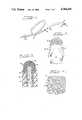
- FIG. 1is a perspective view, partially broken away, of a cardiac pacing lead having a tip electrode assembly that includes a porous member in accordance with the present invention
- FIG. 2is an enlarged elevational view of the distal end portion and electrode of the cardiac pacing lead shown in FIG. 1;
- FIG. 3is a longitudinal cross-sectional view of the distal end portion of the lead and electrode shown in FIG. 2;
- FIG. 4is a further enlarged cross-sectional view showing details of the porous coating shown in FIG. 3;
- FIG. 5is a longitudinal cross-sectional view similar to FIG. 3, but within which the porous coating is overcoated;
- FIG. 6is a further enlarged or magnified cross-sectional view of the porous coating and overcoating shown in FIG. 5;
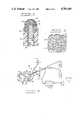
- FIG. 7is a generally schematic view of the preferred plasma deposition system suitable for laying down the porous coating of ceramic particles.
- FIG. 1An illustration of the type of device within which this invention is incorporated is provided by FIG. 1.
- the particular device illustratedis an implantable pervenous lead, generally designated as 21, which includes a distal tip electrode assembly, generally designated as 22, and a terminal assembly, generally indicated by 23, connected together by a elongated conductor member 24 having a protective and insulative outer sheath or cover 25.
- the terminal assembly 23is designed and shaped for use with an implantable cardiac pacemaker (not shown).
- Tip assembly 22provides an exterior electrically conductive surface and includes an electrode 26 having a porous surface for contacting the tissue that is to be stimulated by the cardiac pacer. If desired, fins or tines 27 can be included in order to enhance the stability of the implanted distal tip electrode assembly 22.
- the illustrated conductor member 24is a tightly wound helical metal coil, and the outer sheath is a polymer such as polyurethane or the like that generally encases and is typically bonded to the conductor member 24.
- the electrode 26includes a conductive shaft 28 having a porous coating 29 thereover. Porous coating 29 includes a plurality of ceramic particles 31 that had been formed and deposited as described herein, such ceramic particles 31 having areas of substantially free space or pores 32 therebetween.
- the porous coating 29is overlain with a conductive coating 33.
- this conductive coating 33is of one or more carbon layers which may be laid down by any suitable method, such as by the use of plasma deposition techniques, through the use of a conductive epoxy, or by means of similar procedures.
- porous coating 29such is laid down by a plasma spraying technique which can be carried out on an apparatus of the type generally illustrated in FIG. 7.
- the member to be rendered porous, such as the conductive shaft 28is supported within a jig or fixture 34, which may be a component of a rotatable or otherwise movable platform 45 by virtue of which several shafts 28 or the like are mounted.
- the mountingmay be in a manner whereby multiple shafts 28 or the like can be generally simultaneously subjected to plasma spraying in order to form the porous coating 29 thereonto.
- Robot controlled equipmentcan be used. If the surface of the device being coated such as the conductive shaft 28 is too smooth, its surface can be roughened in a previous operation such as by grit blasting, exemplary grit in this regard being alumina particles.
- a typical electrode shaft 28preferably will be made of titanium or a titanium alloy, or other materials such as those including tantalum or tungsten.
- the ceramic powder of the metal particles 31is a conductive ceramic material such as titanium carbide, titanium nitride, titanium bromide, tungsten carbide, tungsten nitride, tungsten bromide, tantalum carbide, tantalum nitride, tantalum bromide, mixtures thereof, and the like.
- the ceramic powderincludes a blend of a carbide and a bromide of the same metal, for example a blend of titanium bromide powder and titanium carbide powder, or a blend of a nitride and a bromide of the same metal, or the like.
- the powderis free-flowing and typically has a particle size distribution of between about -125 to 325 mesh size (U.S. Standard Mesh Size).
- the resulting porous coating 29will typically exhibit a porosity, which is the total volume of the pores 32, of between about 10 percent and about 15 percent by volume, based on the total volume of the porous coating 29.
- Plasma reactor assembly 36includes a reactor tube or chamber 37, a conductive coil 38 wrapped therearound, and a radio frequency (or RF) power source 39 which is the source of RF power that is transmitted into the internal volume of the reactor tube or chamber 37, which power transmission is preferably carried out in conjunction with a heating arc assembly 41 at or near the distal end of the reactor tube or chamber 37.
- the RF power source 39heats the plasma reactor assembly 36 and the heating arc assembly 41 provides heat energy to the extent that the temperature at the heating arc assembly 41 will be on the order of 6,000° C. (approximately 10,800° F.) and above in order to carry out flamed, plasma spraying of the ceramic material.
- gasesflow into and through the reactor tube or chamber 37 in order to provide the atmosphere that is plasma reacted within the reactor assembly 36.
- gasesflow into and through the reactor tube or chamber 37 in order to provide the atmosphere that is plasma reacted within the reactor assembly 36.
- gas supplies 42 and 43are included.
- the gas suppliesmix with the ceramic material powder within the reactor tube or chamber 37, which mixture is subjected to RF energy and is plasma sprayed from the reactor tube or chamber 37, such as through a nozzle 44, whereby the plasma discharge is directed to the surface onto which the porous coating of ceramic material is being deposited.
- a plurality of jigs 34mount a plurality of conductive shafts 28 or the like, which, for example, are rotated into the area of the nozzle 44 by the operation of the platform 45 or other suitable assembly that is rotatable and/or otherwise movable in association with the plasma reactor assembly 36, which may or may not be movable, such that the plasma discharge from the plasma reactor assembly 36 will coat all desired surfaces of the conductive shafts 28 and the like. Movement of the plasma reactor assembly 36 typically will include reciprocating or back-and-forth motion so that a suitable plasma deposit pattern is followed in order to lay down the desired porous coating 29.
- conductive shaft 28 or the likemay be provided in order to prevent plasma deposition of the ceramic material articles onto selected locations of the conductive shaft 28 or the like onto which the porous ceramic coating is not to be deposited.
- the sides of the conductive shafts 28 or the likeare coated.
- Several hundred conductive shafts 28 or the likecan be imparted with a porous coating according to this invention during a single operation without requiring extensive fixturing.
- the plasma reactor assembly 36causes the ceramic material particles to become molten, and these molten ceramic droplets are sprayed onto each conductive shaft 28 or the like. Because the conductive shaft 28 or the like is at approximately room temperature, the molten droplets solidify or "freeze", during which solidification procedure they are fused onto the surface of each conductive shaft 28 or the like. Such molten droplets likewise also fuse generally together to form the porous coating 29 having the pores 32. It will be observed that, because the ceramic particles are melted, the shape of the ceramic material powder within the reservoir 35 is not particularly critical since the particles are melted and are thereby modified from their original configuration.
- each conductive shaft 28 or the likewill be raised to a relatively low temperature of on the order of about 300° C. (approximately 570° F.), such heating being due to the absorption of heat from the molten ceramic droplets.
- This temperatureis significantly lower than temperatures to which substrates and coatings must be subjected in previously practiced sintering procedures.
- the thickness of the porous coating 29will typically range from between about 20 and 300 microns, but can be as thick as up to about 500 microns.
- the gases provided by the gas supplies 42, 43provide a reductive atmosphere.
- the reductive atmosphereincludes a generally inert gas in combination with a gas having superior reductive properties.
- the preferred gas having reductive propertiesis hydrogen gas, and inert gases include argon, helium and neon.
- the preferred reductive atmosphereis provided by a supply of argon and a supply of hydrogen.
- the resulting porous coated conductive shaft 28is spot welded at a non-administration surface thereof to the conductor member 24, after which the protective and insulative outer sheath or cover 25 is applied as needed in order to cover all or substantially all of the outer surface of the conductor member 24.
- the fins or tines 27 or the likeare bonded onto or otherwise formed on the protective and insulative outer sheath of cover 25.
- the illustrative embodiment of a porous device or element according to this inventiontakes the form of a conductive shaft for forming a tip electrode of a pervenous lead.
- the inventionis suitable for preparing various other implantable devices or components thereof having a conductive porous surface. Examples include blood engaging elements of heart valves, blood pumps, and the like.
- the ceramic coatingis biocompatible and is insoluble in biological fluids and substantially all solvents.
- the conductive ceramic porous coating 29can be overlaid by the conductive carbon coating 33 shown in FIG. 5 and in FIG. 6.
- Such a carbon coating 33is applied by an appropriate method, such as by plasma deposition, by conductive epoxy procedures, or by similar methods.
- plasma deposition techniquesare generally known, it is to be understood that when the term plasma is used herein, such refers to a state that a gas achieves when it is excited to the point of ionization, which is the region in which an active species of the gas is actually formed.
- the excitationis achieved in the present instance by the energy from the RF power source 39 which is conveyed to the gaseous environment within the illustrated plasma reactor assembly 36.
- more conventional deposition methodssuch as sintering under vacuum or under atmospheric pressure, isostatic methods, pressing, brazing or other general coating methods could be used to apply the ceramic powder, such conventional coating methods typically would not realize the economic advantages of high speed production that is achieved by the plasma procedure.
Landscapes
- Health & Medical Sciences (AREA)
- Heart & Thoracic Surgery (AREA)
- Vascular Medicine (AREA)
- Cardiology (AREA)
- Engineering & Computer Science (AREA)
- Biomedical Technology (AREA)
- Nuclear Medicine, Radiotherapy & Molecular Imaging (AREA)
- Radiology & Medical Imaging (AREA)
- Life Sciences & Earth Sciences (AREA)
- Animal Behavior & Ethology (AREA)
- General Health & Medical Sciences (AREA)
- Public Health (AREA)
- Veterinary Medicine (AREA)
- Materials For Medical Uses (AREA)
Abstract
Description
Claims (11)
Priority Applications (1)
| Application Number | Priority Date | Filing Date | Title |
|---|---|---|---|
| US06/898,006US4784160A (en) | 1986-08-19 | 1986-08-19 | Implantable device having plasma sprayed ceramic porous surface |
Applications Claiming Priority (1)
| Application Number | Priority Date | Filing Date | Title |
|---|---|---|---|
| US06/898,006US4784160A (en) | 1986-08-19 | 1986-08-19 | Implantable device having plasma sprayed ceramic porous surface |
Publications (1)
| Publication Number | Publication Date |
|---|---|
| US4784160Atrue US4784160A (en) | 1988-11-15 |
Family
ID=25408786
Family Applications (1)
| Application Number | Title | Priority Date | Filing Date |
|---|---|---|---|
| US06/898,006Expired - LifetimeUS4784160A (en) | 1986-08-19 | 1986-08-19 | Implantable device having plasma sprayed ceramic porous surface |
Country Status (1)
| Country | Link |
|---|---|
| US (1) | US4784160A (en) |
Cited By (42)
| Publication number | Priority date | Publication date | Assignee | Title |
|---|---|---|---|---|
| US4928689A (en)* | 1989-05-15 | 1990-05-29 | Cardiac Pacemakers, Inc. | Rate adaptive cardiac pacer system having living cell tissue for sensing physiologic demand |
| US4976703A (en)* | 1988-02-22 | 1990-12-11 | Siemens Aktiengesellschaft | Medical catheter for intravascular long-term infusion of medication with polysiloxane hydrogel coating |
| US5074313A (en)* | 1989-03-20 | 1991-12-24 | Cardiac Pacemakers, Inc. | Porous electrode with enhanced reactive surface |
| US5097843A (en)* | 1990-04-10 | 1992-03-24 | Siemens-Pacesetter, Inc. | Porous electrode for a pacemaker |
| DE4126363A1 (en)* | 1991-08-06 | 1993-02-11 | Biotronik Mess & Therapieg | Cardiac pacemaker with efficiency detection - has differentiating element producing output signal as measure of cardiac activity |
| DE4231600A1 (en)* | 1992-09-17 | 1994-03-24 | Biotronik Mess & Therapieg | Implantable defibrillation system |
| DE4231603A1 (en)* | 1992-09-17 | 1994-03-24 | Biotronik Mess & Therapieg | Pacemaker system |
| US5330525A (en)* | 1993-04-29 | 1994-07-19 | Medtronic, Inc. | Epicardial lead having dual rotatable anchors |
| US5385761A (en)* | 1990-05-08 | 1995-01-31 | I.T.M. Corporation | Discharge element, method of producing the same and apparatus comprising the same |
| US5397343A (en)* | 1993-12-09 | 1995-03-14 | Medtronic, Inc. | Medical electrical lead having counter fixation anchoring system |
| US5408744A (en)* | 1993-04-30 | 1995-04-25 | Medtronic, Inc. | Substrate for a sintered electrode |
| EP0668087A1 (en)* | 1994-02-01 | 1995-08-23 | Medtronic, Inc. | Drug eluting stitch-in chronic lead |
| US5498004A (en)* | 1991-09-30 | 1996-03-12 | Kulite Tungsten Corporation | Game dart |
| US5545207A (en)* | 1994-08-24 | 1996-08-13 | Medtronic, Inc. | Medical electrical lead having stable fixation system |
| US5571158A (en)* | 1991-08-06 | 1996-11-05 | Biotronik Mess- Und Therapiegeraete Gmbh & Co. Ingenieurbuero Berlin | Stimulation Electrode |
| US5614246A (en)* | 1994-11-10 | 1997-03-25 | Pacesetter Ab | Method for manufacturing a sensor electrode |
| US5766527A (en)* | 1993-10-29 | 1998-06-16 | Medtronic, Inc. | Method of manufacturing medical electrical lead |
| US5972027A (en)* | 1997-09-30 | 1999-10-26 | Scimed Life Systems, Inc | Porous stent drug delivery system |
| EP0796634A3 (en)* | 1996-03-21 | 1999-11-17 | BIOTRONIK Mess- und Therapiegeräte GmbH & Co Ingenieurbüro Berlin | Implantable stimulation electrode |
| US20030157151A1 (en)* | 1998-08-07 | 2003-08-21 | Juergen Pensel | Medical apparatus |
| US6615483B2 (en) | 2000-09-18 | 2003-09-09 | St. Jude Medical Ab | Method for coating a tip region of a multipolar electrode lead |
| US20030204233A1 (en)* | 2002-04-29 | 2003-10-30 | Laske Timothy G. | Pacing method and apparatus |
| US20040064158A1 (en)* | 2002-09-30 | 2004-04-01 | Klein George J. | Multipolar pacing method and apparatus |
| US20040133258A1 (en)* | 2002-11-20 | 2004-07-08 | W. C. Heraeus Gmbh & Co. Kg | Stimulation electrode and its use |
| US6799076B2 (en)* | 1999-12-07 | 2004-09-28 | Greatbatch-Hittman, Inc. | Coated electrode and method of making a coated electrode |
| US20050075708A1 (en)* | 2002-11-26 | 2005-04-07 | O'brien Robert C. | Nanotube coatings for implantable electrodes |
| US20050098563A1 (en)* | 2003-11-11 | 2005-05-12 | Leica Microsystems Nussloch Gmbh | Cryostat with an inner container for receiving a microtome |
| US20050145721A1 (en)* | 2000-11-17 | 2005-07-07 | Mclaws Brent D. | Microdot application method and system |
| US20060167536A1 (en)* | 2005-01-25 | 2006-07-27 | Nygren Lea A | Method for fabrication of low-polarization implantable stimulation electrode |
| US20060184251A1 (en)* | 2005-01-07 | 2006-08-17 | Zongtao Zhang | Coated medical devices and methods of making and using |
| US20070181221A1 (en)* | 2004-03-13 | 2007-08-09 | Pickford Martin E L | Metal implants |
| US20070233217A1 (en)* | 2006-03-31 | 2007-10-04 | Zhongping Yang | Implantable medical electrode |
| US20080069854A1 (en)* | 2006-08-02 | 2008-03-20 | Inframat Corporation | Medical devices and methods of making and using |
| US20080124373A1 (en)* | 2006-08-02 | 2008-05-29 | Inframat Corporation | Lumen - supporting devices and methods of making and using |
| US20080183260A1 (en)* | 2007-01-31 | 2008-07-31 | Nygren Lea A | Medical electrode including an iridium oxide surface and methods of fabrication |
| US20080269829A1 (en)* | 2007-04-26 | 2008-10-30 | Medtronic, Inc. | Metal injection molded titanium alloy housing for implantable medical devices |
| WO2008140376A1 (en)* | 2007-05-14 | 2008-11-20 | St. Jude Medical Ab | Tantalum electrode |
| US20090198344A1 (en)* | 2006-06-12 | 2009-08-06 | Accentus Plc | Metal Implants |
| US20100032309A1 (en)* | 2002-04-16 | 2010-02-11 | Accentus Plc | Metal Implants |
| US20100136083A1 (en)* | 2007-01-15 | 2010-06-03 | Accentus Plc | Metal Implants |
| US20110014399A1 (en)* | 2002-12-13 | 2011-01-20 | W.C. Heraeus Gmbh | Method for producing a stimulation electrode |
| US8858775B2 (en) | 2007-10-03 | 2014-10-14 | Accentus Medical Limited | Method of manufacturing metal with biocidal properties |
Citations (9)
| Publication number | Priority date | Publication date | Assignee | Title |
|---|---|---|---|---|
| US4011861A (en)* | 1974-04-03 | 1977-03-15 | Case Western Reserve University | Implantable electric terminal for organic tissue |
| US4101984A (en)* | 1975-05-09 | 1978-07-25 | Macgregor David C | Cardiovascular prosthetic devices and implants with porous systems |
| US4280514A (en)* | 1975-05-09 | 1981-07-28 | Macgregor David C | Endocardial pacemaker electrode |
| US4281669A (en)* | 1975-05-09 | 1981-08-04 | Macgregor David C | Pacemaker electrode with porous system |
| US4440178A (en)* | 1980-12-23 | 1984-04-03 | Kontron Ag | Implantable electrode |
| US4542752A (en)* | 1983-04-22 | 1985-09-24 | Cordis Corporation | Implantable device having porous surface with carbon coating |
| US4602637A (en)* | 1983-01-11 | 1986-07-29 | Siemens Aktiengesellschaft | Heart pacemaker system |
| US4603704A (en)* | 1983-01-11 | 1986-08-05 | Siemens Aktiengesellschaft | Electrode for medical applications |
| US4606929A (en)* | 1984-12-20 | 1986-08-19 | Petrakov Vladimir P | Method of ionized-plasma spraying and apparatus for performing same |
- 1986
- 1986-08-19USUS06/898,006patent/US4784160A/ennot_activeExpired - Lifetime
Patent Citations (10)
| Publication number | Priority date | Publication date | Assignee | Title |
|---|---|---|---|---|
| US4011861A (en)* | 1974-04-03 | 1977-03-15 | Case Western Reserve University | Implantable electric terminal for organic tissue |
| US4101984A (en)* | 1975-05-09 | 1978-07-25 | Macgregor David C | Cardiovascular prosthetic devices and implants with porous systems |
| US4280514A (en)* | 1975-05-09 | 1981-07-28 | Macgregor David C | Endocardial pacemaker electrode |
| US4281669A (en)* | 1975-05-09 | 1981-08-04 | Macgregor David C | Pacemaker electrode with porous system |
| US4355426A (en)* | 1975-05-09 | 1982-10-26 | Macgregor David C | Porous flexible vascular graft |
| US4440178A (en)* | 1980-12-23 | 1984-04-03 | Kontron Ag | Implantable electrode |
| US4602637A (en)* | 1983-01-11 | 1986-07-29 | Siemens Aktiengesellschaft | Heart pacemaker system |
| US4603704A (en)* | 1983-01-11 | 1986-08-05 | Siemens Aktiengesellschaft | Electrode for medical applications |
| US4542752A (en)* | 1983-04-22 | 1985-09-24 | Cordis Corporation | Implantable device having porous surface with carbon coating |
| US4606929A (en)* | 1984-12-20 | 1986-08-19 | Petrakov Vladimir P | Method of ionized-plasma spraying and apparatus for performing same |
Cited By (71)
| Publication number | Priority date | Publication date | Assignee | Title |
|---|---|---|---|---|
| US4976703A (en)* | 1988-02-22 | 1990-12-11 | Siemens Aktiengesellschaft | Medical catheter for intravascular long-term infusion of medication with polysiloxane hydrogel coating |
| US5074313A (en)* | 1989-03-20 | 1991-12-24 | Cardiac Pacemakers, Inc. | Porous electrode with enhanced reactive surface |
| US4928689A (en)* | 1989-05-15 | 1990-05-29 | Cardiac Pacemakers, Inc. | Rate adaptive cardiac pacer system having living cell tissue for sensing physiologic demand |
| US5097843A (en)* | 1990-04-10 | 1992-03-24 | Siemens-Pacesetter, Inc. | Porous electrode for a pacemaker |
| US5330700A (en)* | 1990-04-10 | 1994-07-19 | Siemens Pacesetter, Inc. | Porous electrode for a pacemaker and method of making same |
| US5385761A (en)* | 1990-05-08 | 1995-01-31 | I.T.M. Corporation | Discharge element, method of producing the same and apparatus comprising the same |
| DE4126363A1 (en)* | 1991-08-06 | 1993-02-11 | Biotronik Mess & Therapieg | Cardiac pacemaker with efficiency detection - has differentiating element producing output signal as measure of cardiac activity |
| DE4126363B4 (en)* | 1991-08-06 | 2004-11-04 | Biotronik Gmbh & Co. Kg | Cardiac pacemaker with means for effectiveness detection |
| US5571158A (en)* | 1991-08-06 | 1996-11-05 | Biotronik Mess- Und Therapiegeraete Gmbh & Co. Ingenieurbuero Berlin | Stimulation Electrode |
| US5498004A (en)* | 1991-09-30 | 1996-03-12 | Kulite Tungsten Corporation | Game dart |
| DE4231603A1 (en)* | 1992-09-17 | 1994-03-24 | Biotronik Mess & Therapieg | Pacemaker system |
| DE4231600A1 (en)* | 1992-09-17 | 1994-03-24 | Biotronik Mess & Therapieg | Implantable defibrillation system |
| US5632770A (en)* | 1992-09-17 | 1997-05-27 | Biotronik Mess-Und Therapiegeraete Gmbh & Co. | Implantable defibrillation system with lead having improved porous surface coating |
| US5609611A (en)* | 1992-09-17 | 1997-03-11 | Biotronik Mess-Und Therapiegeraete Gmbh & Co. Ingenieurbuero Berlin | Pacemaker system with porous electrode and residual charge or after-potential reduction |
| DE4231600B4 (en)* | 1992-09-17 | 2004-08-12 | Biotronik Meß- und Therapiegeräte GmbH & Co. Ingenieurbüro Berlin | Implantable defibrillation system |
| US5330525A (en)* | 1993-04-29 | 1994-07-19 | Medtronic, Inc. | Epicardial lead having dual rotatable anchors |
| US5408744A (en)* | 1993-04-30 | 1995-04-25 | Medtronic, Inc. | Substrate for a sintered electrode |
| US5766527A (en)* | 1993-10-29 | 1998-06-16 | Medtronic, Inc. | Method of manufacturing medical electrical lead |
| US5853652A (en)* | 1993-10-29 | 1998-12-29 | Medtronic, Inc. | Method of manufacturing a medical electrical lead |
| US5397343A (en)* | 1993-12-09 | 1995-03-14 | Medtronic, Inc. | Medical electrical lead having counter fixation anchoring system |
| US5489294A (en)* | 1994-02-01 | 1996-02-06 | Medtronic, Inc. | Steroid eluting stitch-in chronic cardiac lead |
| EP0668087A1 (en)* | 1994-02-01 | 1995-08-23 | Medtronic, Inc. | Drug eluting stitch-in chronic lead |
| US5545207A (en)* | 1994-08-24 | 1996-08-13 | Medtronic, Inc. | Medical electrical lead having stable fixation system |
| US5614246A (en)* | 1994-11-10 | 1997-03-25 | Pacesetter Ab | Method for manufacturing a sensor electrode |
| EP0796634A3 (en)* | 1996-03-21 | 1999-11-17 | BIOTRONIK Mess- und Therapiegeräte GmbH & Co Ingenieurbüro Berlin | Implantable stimulation electrode |
| US6253443B1 (en) | 1997-09-30 | 2001-07-03 | Scimed Life Systems, Inc. | Method of forming a stent |
| US7963990B2 (en) | 1997-09-30 | 2011-06-21 | Boston Scientific Scimed, Inc. | Stent drug delivery system |
| US20080288059A1 (en)* | 1997-09-30 | 2008-11-20 | Boston Scientific Scimed Inc. | Stent Drug Delivery System |
| US5972027A (en)* | 1997-09-30 | 1999-10-26 | Scimed Life Systems, Inc | Porous stent drug delivery system |
| US7510724B2 (en)* | 1998-08-07 | 2009-03-31 | Leica Microsystems (Schweiz) Ag | Medical apparatus |
| US20030157151A1 (en)* | 1998-08-07 | 2003-08-21 | Juergen Pensel | Medical apparatus |
| US6799076B2 (en)* | 1999-12-07 | 2004-09-28 | Greatbatch-Hittman, Inc. | Coated electrode and method of making a coated electrode |
| US7194315B1 (en) | 1999-12-07 | 2007-03-20 | Greatbatch-Hittman, Inc. | Coated electrode and method of making a coated electrode |
| US6615483B2 (en) | 2000-09-18 | 2003-09-09 | St. Jude Medical Ab | Method for coating a tip region of a multipolar electrode lead |
| US20050145721A1 (en)* | 2000-11-17 | 2005-07-07 | Mclaws Brent D. | Microdot application method and system |
| US20100036501A1 (en)* | 2002-04-16 | 2010-02-11 | Accentus Plc | Metal Implants |
| US20100032309A1 (en)* | 2002-04-16 | 2010-02-11 | Accentus Plc | Metal Implants |
| US8945363B2 (en) | 2002-04-16 | 2015-02-03 | Accentus Medical Limited | Method of making metal implants |
| US9393349B2 (en) | 2002-04-16 | 2016-07-19 | Accentus Medical Limited | Metal implants |
| US7177704B2 (en) | 2002-04-29 | 2007-02-13 | Medtronic, Inc. | Pacing method and apparatus |
| US20030204233A1 (en)* | 2002-04-29 | 2003-10-30 | Laske Timothy G. | Pacing method and apparatus |
| US8332035B2 (en) | 2002-09-30 | 2012-12-11 | Medtronic, Inc. | Pacing method |
| US20060142814A1 (en)* | 2002-09-30 | 2006-06-29 | Medtronic, Inc. | Pacing method |
| US20040064158A1 (en)* | 2002-09-30 | 2004-04-01 | Klein George J. | Multipolar pacing method and apparatus |
| US20090276000A1 (en)* | 2002-09-30 | 2009-11-05 | Medtronic, Inc. | Pacing method |
| US7529584B2 (en) | 2002-09-30 | 2009-05-05 | Medtronic, Inc. | Pacing method |
| US7082335B2 (en) | 2002-09-30 | 2006-07-25 | Medtronic, Inc. | Multipolar pacing method and apparatus |
| US6901297B2 (en)* | 2002-11-20 | 2005-05-31 | W.C. Heraeus Gmbh & Co. Kg | Stimulation electrode and its use |
| US20040133258A1 (en)* | 2002-11-20 | 2004-07-08 | W. C. Heraeus Gmbh & Co. Kg | Stimulation electrode and its use |
| US7162308B2 (en) | 2002-11-26 | 2007-01-09 | Wilson Greatbatch Technologies, Inc. | Nanotube coatings for implantable electrodes |
| US20050075708A1 (en)* | 2002-11-26 | 2005-04-07 | O'brien Robert C. | Nanotube coatings for implantable electrodes |
| US20110014399A1 (en)* | 2002-12-13 | 2011-01-20 | W.C. Heraeus Gmbh | Method for producing a stimulation electrode |
| US8298608B2 (en) | 2002-12-13 | 2012-10-30 | Heraeus Precious Metals Gmbh & Co. Kg | Method for producing a stimulation electrode |
| US20050098563A1 (en)* | 2003-11-11 | 2005-05-12 | Leica Microsystems Nussloch Gmbh | Cryostat with an inner container for receiving a microtome |
| US9011665B2 (en) | 2004-03-13 | 2015-04-21 | Accentus Medical Limited | Metal implants |
| US20070181221A1 (en)* | 2004-03-13 | 2007-08-09 | Pickford Martin E L | Metal implants |
| US20060184251A1 (en)* | 2005-01-07 | 2006-08-17 | Zongtao Zhang | Coated medical devices and methods of making and using |
| US20060167536A1 (en)* | 2005-01-25 | 2006-07-27 | Nygren Lea A | Method for fabrication of low-polarization implantable stimulation electrode |
| US20100137963A1 (en)* | 2005-01-25 | 2010-06-03 | Medtronic, Inc. | Method for fabrication of low-polarization implantable stimulation electrode |
| US8155754B2 (en)* | 2005-01-25 | 2012-04-10 | Medtronic, Inc. | Method for fabrication of low-polarization implantable stimulation electrode |
| US20070233217A1 (en)* | 2006-03-31 | 2007-10-04 | Zhongping Yang | Implantable medical electrode |
| US20090198344A1 (en)* | 2006-06-12 | 2009-08-06 | Accentus Plc | Metal Implants |
| US20080069854A1 (en)* | 2006-08-02 | 2008-03-20 | Inframat Corporation | Medical devices and methods of making and using |
| US20080124373A1 (en)* | 2006-08-02 | 2008-05-29 | Inframat Corporation | Lumen - supporting devices and methods of making and using |
| US20100136083A1 (en)* | 2007-01-15 | 2010-06-03 | Accentus Plc | Metal Implants |
| US20080183260A1 (en)* | 2007-01-31 | 2008-07-31 | Nygren Lea A | Medical electrode including an iridium oxide surface and methods of fabrication |
| US8996129B2 (en) | 2007-01-31 | 2015-03-31 | Medtronic, Inc. | Medical electrode including an iridium oxide surface and methods of fabrication |
| US7801613B2 (en)* | 2007-04-26 | 2010-09-21 | Medtronic, Inc. | Metal injection molded titanium alloy housing for implantable medical devices |
| US20080269829A1 (en)* | 2007-04-26 | 2008-10-30 | Medtronic, Inc. | Metal injection molded titanium alloy housing for implantable medical devices |
| WO2008140376A1 (en)* | 2007-05-14 | 2008-11-20 | St. Jude Medical Ab | Tantalum electrode |
| US8858775B2 (en) | 2007-10-03 | 2014-10-14 | Accentus Medical Limited | Method of manufacturing metal with biocidal properties |
Similar Documents
| Publication | Publication Date | Title |
|---|---|---|
| US4784160A (en) | Implantable device having plasma sprayed ceramic porous surface | |
| US4784159A (en) | Process for making an implantable device having plasma sprayed metallic porous surface | |
| US6159560A (en) | Process for depositing a metal coating on a metallic component of an electrical structure | |
| US8043454B1 (en) | Method of forming hermetic vias utilizing metal-metal oxides | |
| AU735872B2 (en) | Ultrasonically coated substrate for use in a capacitor and method of manufacture | |
| US6852925B2 (en) | Feed-through assemblies having terminal pins comprising platinum and methods for fabricating same | |
| US20100189879A1 (en) | Method For Providing An Implantable Electrical Lead Wire | |
| CA2500501A1 (en) | A system to deposit a drug on a surface and a method for coating a surface with a drug | |
| EP0147170A2 (en) | Film resistor heater | |
| JPH04227276A (en) | Graftable electrode | |
| JPS63162161A (en) | Ceramic grinding grain coated with metal | |
| EP1645663A3 (en) | Method of electrophorectic deposition of ceramic bodies for use in manufacturing dental appliances | |
| US5158726A (en) | Process for production of ceramic shaped product having granule layer on the surface and ceramic implant material | |
| US5254137A (en) | Method of producing chip-type solid-electrolyte capacitor | |
| US4322458A (en) | Molded ceramic member, particularly of silicon ceramic, and method for the manufacture thereof | |
| CN101506912B (en) | Manufacture of varistors comprising a passivation layer | |
| US5750202A (en) | Preparation of gold-coated molybdenum articles and articles prepared thereby | |
| JPS6360499B2 (en) | ||
| JP5285868B2 (en) | Magnetron stem manufacturing method | |
| JP2006278103A (en) | Manufacturing method of coating getter film for electron tube | |
| JPH03108237A (en) | Liquid metal ion source | |
| JP2000277239A (en) | Ceramic heater | |
| JPH072171B2 (en) | Method for manufacturing implant member | |
| JPS60255964A (en) | Thermal spraying material for thermal spraying machine | |
| JP2853221B2 (en) | Manufacturing method of composite implant material |
Legal Events
| Date | Code | Title | Description |
|---|---|---|---|
| AS | Assignment | Owner name:SOUTHEAST BANK, N.A., MIDLAD BANK PLC (SINGAPORE B Free format text:SECURITY INTEREST;ASSIGNOR:CORDIS LEADS, INC., A CORP. OF DE;REEL/FRAME:004747/0320 Effective date:19870612 Owner name:CORDIS CORPORATION, MIAMI, FL A CORP. OF FL Free format text:ASSIGNMENT OF ASSIGNORS INTEREST.;ASSIGNOR:SZILAGYI, PAUL J.;REEL/FRAME:004724/0169 Effective date:19860811 | |
| AS | Assignment | Owner name:SOUTHEAST BANK, N.A., MIDLAND BANK PLC (SINGAPORE Free format text:SECURITY INTEREST;ASSIGNOR:CORDIS HEADS, INC.;REEL/FRAME:004734/0550 Effective date:19870630 | |
| AS | Assignment | Owner name:CORDIS LEADS, INC., 10555 WEST FLAGLER STREET, MIA Free format text:ASSIGNMENT OF ASSIGNORS INTEREST.;ASSIGNOR:CORDIS CORPORATION, A CORP. OF FLORIDA;REEL/FRAME:004747/0313 Effective date:19870430 Owner name:CORDIS LEADS, INC., FLORIDA Free format text:ASSIGNMENT OF ASSIGNORS INTEREST;ASSIGNOR:CORDIS CORPORATION, A CORP. OF FLORIDA;REEL/FRAME:004747/0313 Effective date:19870430 | |
| AS | Assignment | Owner name:SOUTHEAST BANK, N.A. Free format text:SECURITY INTEREST;ASSIGNOR:CORDIS LEADS, INC., A DE CORP.;REEL/FRAME:004896/0205 Effective date:19880602 | |
| AS | Assignment | Owner name:SOUTHEAST BANK, N.A., AS SECURITY AGENT Free format text:SECURITY INTEREST;ASSIGNOR:CORDIS LEADS, INC., A CORP. OF DE;REEL/FRAME:004896/0372 Effective date:19880610 | |
| STCF | Information on status: patent grant | Free format text:PATENTED CASE | |
| AS | Assignment | Owner name:TELECTRONICS, INC., A DE CORP., CONNECTICUT Free format text:NUNC PRO TUNC ASSIGNMENT;ASSIGNOR:TPL-CORDIS, INC.;REEL/FRAME:005003/0166 Effective date:19881130 Owner name:TPL-CORDIS, INC., A DE CORP., FLORIDA Free format text:NUNC PRO TUNC ASSIGNMENT;ASSIGNOR:CORDIS LEADS, INC.;REEL/FRAME:005003/0158 Effective date:19881130 Owner name:CORDIS LEADS, INC., 10555 W. FLAGLER STR., MIAMI, Free format text:RELEASED BY SECURED PARTY;ASSIGNOR:SOUTHEAST BANK, N.A., MIDLAND BANK PLC AND CREDIT LYONNAIS;REEL/FRAME:004996/0829 Effective date:19880615 | |
| AS | Assignment | Owner name:TELECTRONICS, U.S.A., INC., CONNECTICUT Free format text:RELEASED BY SECURED PARTY;ASSIGNOR:SOUTHEAST BANK N.A.;REEL/FRAME:005181/0530 Effective date:19890831 | |
| FPAY | Fee payment | Year of fee payment:4 | |
| AS | Assignment | Owner name:TELECTRONICS PACING SYSTEMS, INC., COLORADO Free format text:ASSIGNORS HEREBY CONFIRMS THE ENTIRE INTEREST IN SAID INVENTIONS TO ASSIGNEE ELECUTED ON SEPT. 16, 1988;ASSIGNORS:TELECTRONICS PTY. LTD.;MEDICAL TELECTRONICS HOLDING & FINANCE CO.;TELECTRONIC NV;AND OTHERS;REEL/FRAME:006172/0028 Effective date:19920622 | |
| FEPP | Fee payment procedure | Free format text:PAYOR NUMBER ASSIGNED (ORIGINAL EVENT CODE: ASPN); ENTITY STATUS OF PATENT OWNER: LARGE ENTITY | |
| FPAY | Fee payment | Year of fee payment:8 | |
| AS | Assignment | Owner name:TELECTRONICS PACING SYSTEMS, INC., COLORADO Free format text:CORRECTIVE ASSIGNMENT TO CORRECT ASSIGNEE'S STATE OF INCORPORATION. AN ASSIGNMENT WAS PREVIOUSLY RECORDED AT REEL 6172, FRAME 0028;ASSIGNORS:TELECTRONICS PTY. LTD., AN AUSTRALIAN COMPANY;MEDICAL TELECTRONICS HOLDING & FINANCE CO. (BV), A DUTCH COMPANY;TELECTRONICS NV, A COMPANY OF THE NETHERLANDS ANTILLES;AND OTHERS;REEL/FRAME:008321/0072 Effective date:19961101 | |
| AS | Assignment | Owner name:PACESETTER, INC., CALIFORNIA Free format text:ASSIGNMENT OF ASSIGNORS INTEREST;ASSIGNOR:TELECTRONICS PACING SYSTEMS;REEL/FRAME:008454/0461 Effective date:19961129 | |
| FEPP | Fee payment procedure | Free format text:PAYOR NUMBER ASSIGNED (ORIGINAL EVENT CODE: ASPN); ENTITY STATUS OF PATENT OWNER: LARGE ENTITY Free format text:PAYER NUMBER DE-ASSIGNED (ORIGINAL EVENT CODE: RMPN); ENTITY STATUS OF PATENT OWNER: LARGE ENTITY | |
| FPAY | Fee payment | Year of fee payment:12 |