US4784118A - Optical viewing device - Google Patents
Optical viewing deviceDownload PDFInfo
- Publication number
- US4784118A US4784118AUS07/043,335US4333587AUS4784118AUS 4784118 AUS4784118 AUS 4784118AUS 4333587 AUS4333587 AUS 4333587AUS 4784118 AUS4784118 AUS 4784118A
- Authority
- US
- United States
- Prior art keywords
- relay
- lenses
- light pipe
- polymeric
- viewing
- Prior art date
- Legal status (The legal status is an assumption and is not a legal conclusion. Google has not performed a legal analysis and makes no representation as to the accuracy of the status listed.)
- Expired - Fee Related
Links
- 230000003287optical effectEffects0.000titledescription12
- 239000000463materialSubstances0.000claimsabstractdescription26
- NIXOWILDQLNWCW-UHFFFAOYSA-Nacrylic acid groupChemical groupC(C=C)(=O)ONIXOWILDQLNWCW-UHFFFAOYSA-N0.000claimsabstractdescription12
- 239000006185dispersionSubstances0.000claimsdescription12
- 230000004075alterationEffects0.000claimsdescription5
- 238000003384imaging methodMethods0.000claimsdescription5
- 238000012937correctionMethods0.000claimsdescription3
- PPBRXRYQALVLMV-UHFFFAOYSA-NStyreneChemical compoundC=CC1=CC=CC=C1PPBRXRYQALVLMV-UHFFFAOYSA-N0.000abstractdescription8
- 229920000515polycarbonatePolymers0.000abstractdescription6
- 239000004417polycarbonateSubstances0.000abstractdescription6
- 238000001746injection mouldingMethods0.000description6
- 238000004519manufacturing processMethods0.000description5
- 230000000712assemblyEffects0.000description4
- 238000000429assemblyMethods0.000description4
- 238000005286illuminationMethods0.000description4
- 239000004033plasticSubstances0.000description4
- 229920003023plasticPolymers0.000description4
- 238000000034methodMethods0.000description3
- 239000004793PolystyreneSubstances0.000description2
- 230000005540biological transmissionEffects0.000description2
- 238000010276constructionMethods0.000description2
- 230000008878couplingEffects0.000description2
- 238000010168coupling processMethods0.000description2
- 238000005859coupling reactionMethods0.000description2
- 238000000227grindingMethods0.000description2
- 239000005337ground glassSubstances0.000description2
- 229920002223polystyrenePolymers0.000description2
- SCUZVMOVTVSBLE-UHFFFAOYSA-Nprop-2-enenitrile;styreneChemical compoundC=CC#N.C=CC1=CC=CC=C1SCUZVMOVTVSBLE-UHFFFAOYSA-N0.000description2
- 238000000926separation methodMethods0.000description2
- 125000006850spacer groupChemical group0.000description2
- 229920000638styrene acrylonitrilePolymers0.000description2
- 230000001225therapeutic effectEffects0.000description2
- 230000000007visual effectEffects0.000description2
- 229920002799BoPETPolymers0.000description1
- 206010010071ComaDiseases0.000description1
- 239000005041Mylar™Substances0.000description1
- 229920006397acrylic thermoplasticPolymers0.000description1
- 239000000853adhesiveSubstances0.000description1
- 230000001070adhesive effectEffects0.000description1
- XAGFODPZIPBFFR-UHFFFAOYSA-NaluminiumChemical compound[Al]XAGFODPZIPBFFR-UHFFFAOYSA-N0.000description1
- 229910052782aluminiumInorganic materials0.000description1
- 230000015556catabolic processEffects0.000description1
- 230000008859changeEffects0.000description1
- 230000006835compressionEffects0.000description1
- 238000007906compressionMethods0.000description1
- 238000001816coolingMethods0.000description1
- 229920001577copolymerPolymers0.000description1
- 238000006731degradation reactionMethods0.000description1
- 238000013461designMethods0.000description1
- 238000007516diamond turningMethods0.000description1
- 230000008030eliminationEffects0.000description1
- 238000003379elimination reactionMethods0.000description1
- 239000000835fiberSubstances0.000description1
- 239000000945fillerSubstances0.000description1
- 239000011521glassSubstances0.000description1
- 238000002347injectionMethods0.000description1
- 239000007924injectionSubstances0.000description1
- 238000003780insertionMethods0.000description1
- 230000037431insertionEffects0.000description1
- 239000003562lightweight materialSubstances0.000description1
- 239000007788liquidSubstances0.000description1
- 210000000056organAnatomy0.000description1
- 238000005498polishingMethods0.000description1
- 229920003229poly(methyl methacrylate)Polymers0.000description1
- 238000002360preparation methodMethods0.000description1
- 230000008569processEffects0.000description1
- 230000009467reductionEffects0.000description1
- 239000010935stainless steelSubstances0.000description1
- 229910001220stainless steelInorganic materials0.000description1
- 239000011145styrene acrylonitrile resinSubstances0.000description1
- ISXSCDLOGDJUNJ-UHFFFAOYSA-Ntert-butyl prop-2-enoateChemical compoundCC(C)(C)OC(=O)C=CISXSCDLOGDJUNJ-UHFFFAOYSA-N0.000description1
- 230000000451tissue damageEffects0.000description1
- 231100000827tissue damageToxicity0.000description1
- 238000007514turningMethods0.000description1
- 210000001835visceraAnatomy0.000description1
- 238000012800visualizationMethods0.000description1
Images

Classifications
- A—HUMAN NECESSITIES
- A61—MEDICAL OR VETERINARY SCIENCE; HYGIENE
- A61B—DIAGNOSIS; SURGERY; IDENTIFICATION
- A61B1/00—Instruments for performing medical examinations of the interior of cavities or tubes of the body by visual or photographical inspection, e.g. endoscopes; Illuminating arrangements therefor
- A61B1/002—Instruments for performing medical examinations of the interior of cavities or tubes of the body by visual or photographical inspection, e.g. endoscopes; Illuminating arrangements therefor having rod-lens arrangements
- A—HUMAN NECESSITIES
- A61—MEDICAL OR VETERINARY SCIENCE; HYGIENE
- A61B—DIAGNOSIS; SURGERY; IDENTIFICATION
- A61B1/00—Instruments for performing medical examinations of the interior of cavities or tubes of the body by visual or photographical inspection, e.g. endoscopes; Illuminating arrangements therefor
- A61B1/00163—Optical arrangements
- A61B1/00165—Optical arrangements with light-conductive means, e.g. fibre optics
Definitions
- This inventionrelates generally to optical viewing devices and more particularly concerns a disposable endoscope for use in viewing a region within a body cavity or the like.
- endoscopeswhich permit visualization of typically inaccessible areas and organs within a patient's body are known. Such optical viewing instruments, or “endoscopes,” can often obviate the need for excising specimens from an internal organ of the living body for examination with a conventional microscope. Also, as disclosed in, for example, U.S. Pat. Nos. 3,677,262 to Zukowski and 4,392,485 to Hiltebrandt, endoscopes may further be provided with a means for supporting and guiding surgical instruments within a patient's body.
- endoscopestypically include a light pipe for illuminating the region to be viewed, at least one lens assembly for focusing and relaying the image of the illuminated object, and a housing for the entire assembly which is structured so as to minimize tissue damage upon examination.
- Examples of such endoscopesmay be found in U.S. Pat. Nos. 3,089,484 to Hett, 3,257,902 to Hopkins, 3,556,085 to Takahashi, 4,267,828 to Matsuo and 4,273,110 to Groux.
- an apparatus for viewing a region within a body cavity or the likewhich enables direct examination of that region.
- the apparatusincludes an elongated light pipe which is designed to direct light from a light source located at its proximal end along its length to its distal end so as to illuminate the region to be examined near its distal end.
- Carried at the distal end of the endoscopeis an objective lens system which includes a plurality of polymeric, preferably aspheric, lens elements. These lens elements are preferably constructed so as to form a focused real image of the illuminated region prior to relay through the device, although the lens elements could also be constructed so as to form a virtual image prior to relay as well.
- a series of polymeric relay lenses mounted on the light pipetransmits the image to a proximal region of the light pipe, where a viewing lens system enables viewing of the relayed image.
- the viewing lens systemcomprises a reversed telephoto lens assembly.
- a light pipehaving an elongate distal section extending from the pipe's distal end to a bend in the pipe adjacent the pipe's proximal end
- the elongate sectionincludes an elongate cradlelike cavity formed therein.
- the cavityserves as a support means for a series of polymeric relay lenses which are aligned end-to-end within it.
- a sealed, elongate, substantially rigid tubeencases the pipe's distal end section and the relay lenses, with the relay lenses being securely wedged between the cavity and the tube so as to maintain the lenses in axial alignment.
- the bend in the light pipeis preferably minimal, i.e. it should substantially eliminate any structural interference with the viewing lens assembly while minimizing loss of light at the bend.
- the field of view provided by these embodimentsis generally on the order of 60° to 70°, although the objective lens assembly may be constructed so as to provide a narrower or wider field of view.
- a Fresnel lens or other opticmay be incorporated within the device at the distal end of the light pipe. Such an assembly refracts the light from the light pipe into a larger cone and thus gives a larger illuminated region. This assembly may also be used to deviate the centroid of the illumination pattern.
- the light pipe and the objective, relay and viewing lens assembliesare preferably all fabricated of a polymeric material which lens itself to injection molding.
- Suitable materialsinclude acrylics, polystyrenes, polycarbonates and styrene-acrylonitrile (SAN) copolymers.
- a means for adapting the device to be coupled to a recording or display meansmay be included at the proximal end of the device.
- a recording meansfor example, a photographic or electronic record may be made of an endoscopic examination.
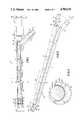
- FIG. 1is a cross-sectional side view of a preferred embodiment of an endoscope embodied by the invention
- FIG. 2is an exploded, perspective view of a preferred embodiment of the endoscope showing the series of rod lenses placed end-to-end within the molded light pipe;
- FIG. 3is a cross-sectional view taken along the 3--3 lines of FIG. 1, and specifically illustrates the placement of one of the rod lenses within the light pipe;
- FIG. 4is an optical layout of a preferred embodiment of the invention and illustrates ray paths and image orientation. The image is exaggerated vertically (approximately 4:1) in the y-direction for clarity.
- optical viewing apparatusis shown generally at 10 and is positioned in FIGS. 1 and 2 so as to enable a viewer 12 to examine a region 24 within a body cavity or the like.
- An elongate light pipe 14 disposed within the apparatus 10is provided with a distal end 18 positioned near the region 24 to be viewed and with a proximal end 16.
- the light pipedirects light from a suitable light source 20 located at proximal end 16 along its length to distal end 18.
- Carried at the distal end of the light pipeis an objective lens system collectively designated 22 which includes a plurality of polymeric lens elements. It is preferred that the polymeric lens elements include at least one aspheric surface to improve the clarity of the image over an extended field of view.
- objective lens system 22includes the following lenses, which preferably provide a focused, real image of the illuminated region at point P, i.e. prior to relay.
- Surface 26 of distal negative lens 28directly receives light reflected from the illuminated region, and is preferably planar in order to avoid change of optical power when the endoscope is immersed in a liquid.
- Lens 28is preferably plano-concave as shown and aspheric on concave surface 25.
- the imageis then processed by primary positive lens 30 which is preferably a double-convex objective lens with two aspheric surfaces.
- Lenses 28 and 30together comprise a reversed telephoto lens that has a relatively short focal length and which covers a field of view on the order of 60° to 70°.
- Field lens 32is located proximal to the image formed by the objective lens 30 and is preferably also a double-convex lens as shown. Like distal negative lens 28, the surfaces 34 and 36 of field lens 32 are preferably aspheric to ensure elimination of spherical and other aberration, i.e. to provide a better degree of correction and to reduce the number of lens elements needed.
- the primary purpose of field lens 32is to reduce or eliminate the vignetting at the edge of the field of view. The lens is placed in the vicinity of the plane of the image.
- Lenses 28, 30 and 32, which together comprise the objective lens assembly herein,are made of a polymeric material such as acrylic, polystyrene, polycarbonate or SAN, preferably of a low dispersion material such as acrylic. Fabrication into suitable structures such as those illustrated may be effected by means of injection molding, conventional grinding and polishing, or diamond turning, although injection molding is the preferred method.
- This placement of lenses 28, 30 and 32 at the distal end of the viewing deviceobviates the need for a focusing assembly, as the device is optimized to provide a focused image for areas viewed within the range of distances generally associated with therapeutic use. Outside of the typical therapeutic range, it is preferred that the device be provided with a focusing means.
- Relay lens assembly 38includes a plurality of rod lenses 40 arranged end-to-end so as to transmit the image provided by objective 22 through the elongate section of the apparatus to its proximal end.
- the relay lensesare fabricated from a polymeric material which lends itself to injection molding, e.g. styrene, polycarbonate, acrylic, SAN and the like. As above, low dispersion materials, acrylic in particular, are preferred.
- the number of relay lensesis selected so as to reduce the number of surface refractions which degrade the image while still allowing for transmission of sufficient light. For direct, visual observation of an area, the number of relay lenses is preferably an odd multiple of 2, i.e. 2(2n+1) where n is zero or an integer.
- a particularly preferred number for such an embodiment which optimizes the aforementioned considerationsis six. As illustrated in FIG. 4, proper image orientation thus typically requires an odd number of symmetrically placed pairs of rod relay lenses. Alternatively, the use of an inverting prism such as a dove prism will allow for the use of an even number of relay lens pairs.
- the image formed at Pis collimated and refocused several times during relay, e.g., where six rod lenses are incorporated within the device, the image will be collimated and refocused three times. Because the placement of rod lenses is symmetrical, correction for lateral chromatic aberration is automatic, that is, inherent in the structure of the relay assembly. The device does not incorporate significant means of correcting for axial color, as the eye is not particularly sensitive to axial chromatic aberration; this allows for a relatively simple and inexpensive construction. The symmetry of the relay system also eliminates distortion and coma.
- the individual rod lensesare difficult to make if not molded, since the radius of curvature is about half the length of the rod (thus, it would be difficult to fit several on a block for grinding).
- the rod lensesare fabricated by injection molding on standard equipment.
- the polymeric materialis emplaced in a suitable mold and heated to at least about 350° C.
- a suitable mold clamping forceis applied, followed by a cooling hold.
- a mold runner diameterabout equal to the diameter of the rod lens optimizes the results obtained.
- the rod lensesare preferably identical, double-convex lenses having entrant and exit refracting surfaces 33 and 35 of the same focal length.
- the length of the rod lensesis thus optimized to allow for transmission of sufficient light while at the same time providing for an endoscope of sufficient physical length.
- the length of each of the rod lensesis designed to be approximately equal to the focal length of the refracting surfaces.
- the lenswill focus a distance nf away from the surface; the overall f-number of the system is thus f/d where d is the diameter of the lens.
- the overall f-number of the relay systemis preferably optimized at between about 4 and 6.
- the diameter of the rod lensesis preferably between about 5 mm and about 7 mm, and the index of refraction for the materials used, e.g. acrylic or styrene, is on the order of about 1.48-1.49.
- a viewing lens system 42is housed adjacent the proximal end of the light pipe, and processes the transmitted image from the relay lens assembly 38.
- a reverse telephoto lens assemblyis used to increase the overall length of the device and the illumination of the image viewed.
- viewing lens system 42includes only two lenses, post-rod lens 44 and positive lens 48, with a window at 46.
- viewing lens assembly 42includes three lenses, negative post-rod lens 44, proximal negative lens 46 (which replaces the window in the reverse telephoto assembly) and a strong positive lens 48 disposed therebetween.
- the post-rod lens 44is preferably plano-concave, with the planar surface 50 facing the relay lens assembly and directly receiving the image transmitted therethrough.
- viewing lenses 44, 46 and 48are fabricated from a suitable low dispersion polymeric material which lends itself to injection molding.
- the light pipeitself is fabricated from a polymeric material such as styrene, acrylic or polycarbonate, preferably from a polymeric material with a relatively high refractive index such as polycarbonate (n ⁇ 1.58).
- the field of view provided by the imaging lens assembly 22is about 60° to about 70°.
- a Fresnel lenssuch as that shown at 52 may be provided so as to disperse light and thereby increase the uniformity of illumination within the field of view.
- the Fresnel lensis incorporated within the structure by placement at the distal end 18 of the light pipe, thereby refracting the light directed onto the region to be examined and providing a wider region of illumination.
- Light pipe 14is provided with an elongate cradlelike cavity 54 along its enlongate distal section 56.
- This cradlelike cavityprovides a support means for the objective lens assembly as well as the relay lens assembly.
- the relay lenses 40extend along the pipe's distal section and are arranged end-to-end as described above.
- a housingsuch as an elongate, substantially rigid tube 58 encases the light pipe 14 as well as the various lens assemblies.
- the tubeis preferably constructed of a relatively strong, lightweight material such as aluminum, stainless steel, plastic and the like.
- the relay lensesare securely wedged between cavity 54 and tube 58 so that the lenses are held in axial alignment along the length of the tube.
- the lenses of imaging lens system 22are wedged between light pipe 14 and tube 58 in the same manner.
- Tube 58is preferably sealed with adhesive, filler, or the like so as to provide an airtight, watertight seal.
- the light pipethus doubles as a mechanical support for the optic train and provides a means for easily aligning and centering the individual lens elements.
- the lens systemscan thus be assembled without the need for complicated aligning fixtures.
- the light pipeis preferably comprised of a polymeric material which can be injection molded, it can also be fabricated from either glass or plastic fibers.
- a shielding means 60such as dark paper, Mylar or other opaque material may be disposed between light pipe 14 and the relay lenses 40 so as to eliminate degradation of the transmitted image by light scattered from the light pipe.
- Shielding means 60also helps baffle nonimaged light, i.e. light from the light pipe is prevented from entering the rod lenses directly.
- Spacers 62 and 64may also be included to provide physical separation of the light pipe 14 from the relay lenses.
- the light pipeis angled at "A" within handle 63 and becomes completely annular proximal to angle "A" where it is coupled to light source 20 by suitable means, e.g. by means of adapters 66 and 68.
- angle Ais preferably minimized at about 30° or less so as to prevent loss of transmitted light.
- Assembly of the endoscopeis a relatively uncomplicated procedure. All lens elements except for distal negative lens 28 are initially placed in shielding paper as described and then inserted into the light pipe. Spacers 29 are provided between the objective system elements so as to ensure axial separation. Distal negative lens 28 caps the distal end of the endoscope as illustrated in FIG. 1, and the remainder of the optic train is slid toward the distal end to set axial spacing. Centering occurs upon sliding of the elements of the optic train into tube 58.
- Light pipe 14 and tube 58are both, as noted above, fabricated from a strong, rigid material so as to prevent buckling during insertion and to ensure sufficient support and centering for the optic train. The pipe is allowed, however, some compression flexibility.
- the inventionalso comprises an optic train of polymeric lens elements, preferably fabricated from a low dispersion, optical quality plastic such as acrylic.
- the optic trainincludes: (1) an objective lens assembly for forming a real image of an illuminated region that is substantially uncorrected for axial color; and (2) a relay lens assembly, similarly substantially uncorrected, which comprises an odd number of symmetrical pairs of polymeric rod lenses (or an even number used in conjunction with an inverted prism), which rod lenses are designed to relay the image along the length of the endoscope to form an image that can be observed and optionally magnified.
- the objective and relay lens assembliesare as described above and illustrated in FIG. 1.
- eyepiece section 70is provided with a means for coupling the viewing device to a display, camera, or other recording means so that a display or a photographic or other record may be made of an endoscopic examination.
- the optical viewing device of the present inventionis relatively inexpensive to fabricate; in contrast to known analogous devices, which are comprised of a number of ground glass lenses and mirrors, the present invention incorporates a large number of inexpensive polymeric components, including the light pipe as well as the relay, objective and viewing lenses.
- the light pipedoubles as the support means for the system of relay lenses, the diameter and overall complexity of the device are substantially reduced.
Landscapes
- Health & Medical Sciences (AREA)
- Life Sciences & Earth Sciences (AREA)
- Surgery (AREA)
- Optics & Photonics (AREA)
- Physics & Mathematics (AREA)
- Medical Informatics (AREA)
- Animal Behavior & Ethology (AREA)
- Radiology & Medical Imaging (AREA)
- Nuclear Medicine, Radiotherapy & Molecular Imaging (AREA)
- Engineering & Computer Science (AREA)
- Biomedical Technology (AREA)
- Heart & Thoracic Surgery (AREA)
- Biophysics (AREA)
- Molecular Biology (AREA)
- Pathology (AREA)
- General Health & Medical Sciences (AREA)
- Public Health (AREA)
- Veterinary Medicine (AREA)
- Endoscopes (AREA)
- Instruments For Viewing The Inside Of Hollow Bodies (AREA)
- Lenses (AREA)
- Glass Compositions (AREA)
- Eye Examination Apparatus (AREA)
- Window Of Vehicle (AREA)
- Measuring Pulse, Heart Rate, Blood Pressure Or Blood Flow (AREA)
Abstract
Description
Claims (34)
Priority Applications (8)
| Application Number | Priority Date | Filing Date | Title |
|---|---|---|---|
| US07/043,335US4784118A (en) | 1987-04-28 | 1987-04-28 | Optical viewing device |
| PCT/US1988/001332WO1988008271A1 (en) | 1987-04-28 | 1988-04-25 | Optical viewing device |
| DE3854156TDE3854156T2 (en) | 1987-04-28 | 1988-04-25 | OPTICAL OBSERVER. |
| EP88904159AEP0358678B1 (en) | 1987-04-28 | 1988-04-25 | Optical viewing device |
| JP63503984AJP2859621B2 (en) | 1987-04-28 | 1988-04-25 | Optical examination device |
| AU17114/88AAU614906B2 (en) | 1987-04-28 | 1988-04-25 | Optical viewing device |
| AT88904159TATE124852T1 (en) | 1987-04-28 | 1988-04-25 | OPTICAL OBSERVATION DEVICE. |
| CA000565287ACA1331594C (en) | 1987-04-28 | 1988-04-27 | Optical viewing device |
Applications Claiming Priority (1)
| Application Number | Priority Date | Filing Date | Title |
|---|---|---|---|
| US07/043,335US4784118A (en) | 1987-04-28 | 1987-04-28 | Optical viewing device |
Publications (1)
| Publication Number | Publication Date |
|---|---|
| US4784118Atrue US4784118A (en) | 1988-11-15 |
Family
ID=21926649
Family Applications (1)
| Application Number | Title | Priority Date | Filing Date |
|---|---|---|---|
| US07/043,335Expired - Fee RelatedUS4784118A (en) | 1987-04-28 | 1987-04-28 | Optical viewing device |
Country Status (8)
| Country | Link |
|---|---|
| US (1) | US4784118A (en) |
| EP (1) | EP0358678B1 (en) |
| JP (1) | JP2859621B2 (en) |
| AT (1) | ATE124852T1 (en) |
| AU (1) | AU614906B2 (en) |
| CA (1) | CA1331594C (en) |
| DE (1) | DE3854156T2 (en) |
| WO (1) | WO1988008271A1 (en) |
Cited By (48)
| Publication number | Priority date | Publication date | Assignee | Title |
|---|---|---|---|---|
| JPH02104315U (en)* | 1989-02-07 | 1990-08-20 | ||
| US4964710A (en)* | 1989-07-27 | 1990-10-23 | Leiner Dennis C | Disposable rigid endoscope |
| US5048508A (en)* | 1989-12-23 | 1991-09-17 | Karl Storz | Endoscope having sealed shaft |
| US5124838A (en)* | 1989-01-31 | 1992-06-23 | Precision Optics Corporation | Optical coupler |
| US5188092A (en)* | 1990-12-13 | 1993-02-23 | United States Surgical Corporation | Disposable rigid endoscope |
| WO1993017362A1 (en)* | 1992-02-19 | 1993-09-02 | United States Surgical Corporation | Optical viewing device |
| US5369525A (en)* | 1992-12-02 | 1994-11-29 | United States Surgical Corporation | Ring lens assembly for an optical viewing device |
| US5406418A (en)* | 1993-07-15 | 1995-04-11 | Precision Optics Corporation | Mechanical coupler for eyepieces |
| US5412504A (en)* | 1993-10-05 | 1995-05-02 | United States Surgical Corporation | Optical system for an endoscope |
| US5416634A (en)* | 1992-09-11 | 1995-05-16 | United States Surgical Corporation | Optical viewing device |
| US5423312A (en)* | 1992-12-18 | 1995-06-13 | Schott Fiber Optics, Inc. | Rigid endoscope having modified high refractive index tunnel rod for image transmission and method of manufacture thereof |
| US5444569A (en)* | 1993-03-12 | 1995-08-22 | Steven Spence Adkinson | Collapsible terrestrial telescope |
| US5485316A (en)* | 1991-10-25 | 1996-01-16 | Olympus Optical Co., Ltd. | Illumination optical system for endoscopes |
| WO1996018125A1 (en)* | 1994-12-06 | 1996-06-13 | Jan Hoogland | Integrated optical system for endoscopes and the like |
| US5539971A (en)* | 1993-09-13 | 1996-07-30 | United States Surgical Corporation | Method of manufacturing an endoscope |
| US5554100A (en)* | 1994-03-24 | 1996-09-10 | United States Surgical Corporation | Arthroscope with shim for angularly orienting illumination fibers |
| US5555131A (en)* | 1994-10-27 | 1996-09-10 | Symbiosis Corporation | Objective lens system for endoscope |
| US5568312A (en)* | 1994-10-27 | 1996-10-22 | Symbiosis Corporation | Relay lens system for endoscope |
| US5573493A (en)* | 1993-10-08 | 1996-11-12 | United States Surgical Corporation | Endoscope attachment for changing angle of view |
| US5576882A (en)* | 1992-04-08 | 1996-11-19 | Olympus Optical Co., Ltd. | Endoscope |
| EP0694800A3 (en)* | 1994-07-26 | 1997-02-05 | United States Surgical Corp | Replicated relay lens system |
| US5632718A (en)* | 1994-03-11 | 1997-05-27 | Olympus Optical Co., Ltd. | Non-flexible endoscope with objective lens system and relay lens system |
| US5684629A (en)* | 1993-10-05 | 1997-11-04 | Monadnock Optics, Inc. | Optical system for endoscope |
| US5701200A (en)* | 1994-10-27 | 1997-12-23 | Symbiosis Corporation | Monolithic relay lens system particularly suited for use in an endoscope |
| US5933275A (en)* | 1995-10-20 | 1999-08-03 | Olympus Optical Co., Ltd. | Optical system for non-flexible endoscopes |
| US5951463A (en)* | 1998-03-18 | 1999-09-14 | Clarus Medical Systems, Inc. | Hand-held endoscopic viewing system |
| US6110106A (en)* | 1998-06-24 | 2000-08-29 | Biomax Technologies, Inc. | Endoscopes and methods relating to direct viewing of a target tissue |
| US20020057501A1 (en)* | 1999-03-08 | 2002-05-16 | Fang Lei | Image transmission system for endoscopes and method of producing a rod lens |
| US6478730B1 (en) | 1998-09-09 | 2002-11-12 | Visionscope, Inc. | Zoom laparoscope |
| US6496465B1 (en)* | 1998-06-09 | 2002-12-17 | Barry G. Broome | Monolithic CD/DVD read/write head |
| US20040252386A1 (en)* | 2001-07-26 | 2004-12-16 | Fang Lei | Image transmission system from three rod lenses for rigid endoscopes |
| US6853485B2 (en) | 1994-12-06 | 2005-02-08 | Jan Hoogland | Integrated optical system for endoscopes and the like |
| US20050085698A1 (en)* | 2003-10-16 | 2005-04-21 | Snecma Moteurs | Endoscope with ultraviolet illumination |
| US20050182297A1 (en)* | 1996-10-04 | 2005-08-18 | Dietrich Gravenstein | Imaging scope |
| US20050200842A1 (en)* | 2003-07-04 | 2005-09-15 | Snecma Moteurs | Apparatus for searching for and detecting defects in parts by endoscopy |
| US7226451B2 (en) | 2003-08-26 | 2007-06-05 | Shluzas Alan E | Minimally invasive access device and method |
| US20070135874A1 (en)* | 2005-11-22 | 2007-06-14 | Bala John L | Endoscope for therapeutic light delivery |
| US20070297056A1 (en)* | 2004-04-02 | 2007-12-27 | Essilor International | Light Pipe For Making An Electronic Display Arrangement |
| US7691120B2 (en) | 2003-08-26 | 2010-04-06 | Zimmer Spine, Inc. | Access systems and methods for minimally invasive surgery |
| US20120038761A1 (en)* | 2010-08-12 | 2012-02-16 | Leica Microsystems (Schweiz) Ag | Microscope System |
| USRE44268E1 (en) | 1997-07-15 | 2013-06-04 | Zimmer Spine, Inc. | Method and instruments for percutaneous arthroscopic disc removal, bone biopsy and fixation of the vertebral |
| US20130272018A1 (en)* | 2011-11-29 | 2013-10-17 | Vladimir Khubiryants | Light Source Including a Ball Lens for Use With a Scope |
| CN103597340A (en)* | 2011-02-28 | 2014-02-19 | 斯奈克玛 | Device for searching for defects on parts by endoscopy |
| US20150011825A1 (en)* | 2012-02-24 | 2015-01-08 | L'HELGOUAL'CH, Guy | Endoscopic device intended, in particular, for a medical usage |
| US20150087912A1 (en)* | 2013-09-20 | 2015-03-26 | Walter Vogel | Endoscope |
| US20150216399A1 (en)* | 2012-09-05 | 2015-08-06 | Olympus Winter & Ibe Gmbh | Video camera housing for an endoscope |
| US10357149B2 (en) | 2005-04-05 | 2019-07-23 | Integrated Endoscopy, Inc. | Medical imaging device using thermally conducting lens cradle |
| US10448806B2 (en) | 2004-04-06 | 2019-10-22 | Integrated Endoscopy, Inc. | Endoscope designs and methods of manufacture |
Families Citing this family (8)
| Publication number | Priority date | Publication date | Assignee | Title |
|---|---|---|---|---|
| US5852511A (en)* | 1993-10-20 | 1998-12-22 | Olympus Optical Co. Ltd | Optical system for non-flexible endoscopes |
| CA2118260A1 (en)* | 1994-05-09 | 1995-11-10 | Robert J. Wood | Stereo imaging assembly for endoscopic probe |
| FR2745170B1 (en)* | 1996-02-22 | 1998-05-15 | Tokendo Sarl | ENDOSCOPE HAVING A SEMI-RIGID ENDOSCOPY DEVICE |
| EP0904725B1 (en) | 1997-02-13 | 2005-09-14 | Matsushita Electric Industrial Co., Ltd. | Endoscope and method of manufacturing the same |
| DE10136956C2 (en)* | 2001-07-28 | 2003-08-14 | Storz Karl Gmbh & Co Kg | Rod lens system for rigid endoscopes |
| US7160248B2 (en)* | 2002-06-06 | 2007-01-09 | Optiscope Technologies Ltd. | Optical device for viewing of cavernous and/or inaccessible spaces |
| EP1693488B1 (en) | 2003-11-21 | 2013-06-19 | National Institute for Materials Science | Lens and optical electronic device |
| DE102009045527A1 (en)* | 2009-10-09 | 2011-04-14 | Henke-Sass Wolf Gmbh | Endoscope has endoscope shaft provided with distal end and proximal end, where monitor opening is locked by transparent cover |
Citations (19)
| Publication number | Priority date | Publication date | Assignee | Title |
|---|---|---|---|---|
| US2482971A (en)* | 1947-07-11 | 1949-09-27 | Golson Kelly Kendall | Self-illuminated transparent proctoscope |
| US3089484A (en)* | 1961-01-26 | 1963-05-14 | American Cystoscope Makers Inc | Flexible optical instrument particularly for carrying out surgical procedures |
| US3257902A (en)* | 1959-07-16 | 1966-06-28 | Watson W & Sons Ltd | Optical system having cylindrical rod-like lenses |
| US3297022A (en)* | 1963-09-27 | 1967-01-10 | American Cystoscope Makers Inc | Endoscope |
| US3414344A (en)* | 1964-01-18 | 1968-12-03 | Mukojima Michi | Flexible optical system for transmitting light or optical images |
| US3556085A (en)* | 1968-02-26 | 1971-01-19 | Olympus Optical Co | Optical viewing instrument |
| US3677262A (en)* | 1970-07-23 | 1972-07-18 | Henry J Zukowski | Surgical instrument illuminating endotracheal tube inserter |
| US3941121A (en)* | 1974-12-20 | 1976-03-02 | The University Of Cincinnati | Focusing fiber-optic needle endoscope |
| SU544422A1 (en)* | 1975-06-12 | 1977-01-30 | Всесоюзный Научно-Исследовательский Институт Медицинского Проборостроения | Endoscope Optical System |
| US4036218A (en)* | 1974-12-19 | 1977-07-19 | Olympus Optical Co., Ltd. | Endoscope |
| US4076018A (en)* | 1974-12-06 | 1978-02-28 | Richard Wolf Gmbh | Endoscopes |
| US4157216A (en)* | 1978-06-26 | 1979-06-05 | Polaroid Corporation | Adapter for optically coupling a photographic camera with a viewing device |
| US4159546A (en)* | 1977-06-15 | 1979-07-03 | Shearing Steven P | Intraocular lens |
| SU683721A1 (en)* | 1977-01-10 | 1979-09-15 | Всесоюзный Научно-Исследовательский Институт Медицинского Приборостроения | Endoscope optical system |
| SU686725A1 (en)* | 1977-03-14 | 1979-09-28 | Всесоюзный Научно-Исследовательский Институт Медицинского Приборостроения | Endoscope optical system |
| US4267828A (en)* | 1979-06-22 | 1981-05-19 | Olympus Optical Co., Ltd. | Endoscope having an extension guide for observation |
| US4273110A (en)* | 1978-07-13 | 1981-06-16 | Jean Groux | Ultraviolet endoscope |
| US4319563A (en)* | 1977-12-02 | 1982-03-16 | Olympus Optical Co., Ltd. | Endoscope with a smoothly curved distal end face |
| US4392485A (en)* | 1981-02-17 | 1983-07-12 | Richard Wolf Gmbh | Endoscope |
Family Cites Families (6)
| Publication number | Priority date | Publication date | Assignee | Title |
|---|---|---|---|---|
| DE943430C (en)* | 1955-04-29 | 1956-05-17 | Richard Wolf | Optical observation system, especially gastroscope |
| US3970362A (en)* | 1972-01-21 | 1976-07-20 | American Optical Corporation | Process of producing polarizing optical devices and product thereof |
| US4148551A (en)* | 1977-05-09 | 1979-04-10 | American Hospital Supply Corporation | Modular rod lens assembly and method of making the same |
| DE3005479A1 (en)* | 1980-02-14 | 1981-08-20 | Richard Wolf Gmbh, 7134 Knittlingen | Endoscope with shaft and optical system - has number of focusing lens pairs reversing image received through ocular funnel and link pipe |
| DE3046663A1 (en)* | 1980-12-11 | 1982-07-15 | Fa. Carl Zeiss, 7920 Heidenheim | JOINT OPTICS |
| US4927222A (en)* | 1986-06-16 | 1990-05-22 | Shiley Incorporated | Dual optical fiber device |
- 1987
- 1987-04-28USUS07/043,335patent/US4784118A/ennot_activeExpired - Fee Related
- 1988
- 1988-04-25JPJP63503984Apatent/JP2859621B2/ennot_activeExpired - Lifetime
- 1988-04-25EPEP88904159Apatent/EP0358678B1/ennot_activeExpired - Lifetime
- 1988-04-25DEDE3854156Tpatent/DE3854156T2/ennot_activeExpired - Fee Related
- 1988-04-25ATAT88904159Tpatent/ATE124852T1/ennot_activeIP Right Cessation
- 1988-04-25AUAU17114/88Apatent/AU614906B2/ennot_activeCeased
- 1988-04-25WOPCT/US1988/001332patent/WO1988008271A1/enactiveIP Right Grant
- 1988-04-27CACA000565287Apatent/CA1331594C/ennot_activeExpired - Fee Related
Patent Citations (19)
| Publication number | Priority date | Publication date | Assignee | Title |
|---|---|---|---|---|
| US2482971A (en)* | 1947-07-11 | 1949-09-27 | Golson Kelly Kendall | Self-illuminated transparent proctoscope |
| US3257902A (en)* | 1959-07-16 | 1966-06-28 | Watson W & Sons Ltd | Optical system having cylindrical rod-like lenses |
| US3089484A (en)* | 1961-01-26 | 1963-05-14 | American Cystoscope Makers Inc | Flexible optical instrument particularly for carrying out surgical procedures |
| US3297022A (en)* | 1963-09-27 | 1967-01-10 | American Cystoscope Makers Inc | Endoscope |
| US3414344A (en)* | 1964-01-18 | 1968-12-03 | Mukojima Michi | Flexible optical system for transmitting light or optical images |
| US3556085A (en)* | 1968-02-26 | 1971-01-19 | Olympus Optical Co | Optical viewing instrument |
| US3677262A (en)* | 1970-07-23 | 1972-07-18 | Henry J Zukowski | Surgical instrument illuminating endotracheal tube inserter |
| US4076018A (en)* | 1974-12-06 | 1978-02-28 | Richard Wolf Gmbh | Endoscopes |
| US4036218A (en)* | 1974-12-19 | 1977-07-19 | Olympus Optical Co., Ltd. | Endoscope |
| US3941121A (en)* | 1974-12-20 | 1976-03-02 | The University Of Cincinnati | Focusing fiber-optic needle endoscope |
| SU544422A1 (en)* | 1975-06-12 | 1977-01-30 | Всесоюзный Научно-Исследовательский Институт Медицинского Проборостроения | Endoscope Optical System |
| SU683721A1 (en)* | 1977-01-10 | 1979-09-15 | Всесоюзный Научно-Исследовательский Институт Медицинского Приборостроения | Endoscope optical system |
| SU686725A1 (en)* | 1977-03-14 | 1979-09-28 | Всесоюзный Научно-Исследовательский Институт Медицинского Приборостроения | Endoscope optical system |
| US4159546A (en)* | 1977-06-15 | 1979-07-03 | Shearing Steven P | Intraocular lens |
| US4319563A (en)* | 1977-12-02 | 1982-03-16 | Olympus Optical Co., Ltd. | Endoscope with a smoothly curved distal end face |
| US4157216A (en)* | 1978-06-26 | 1979-06-05 | Polaroid Corporation | Adapter for optically coupling a photographic camera with a viewing device |
| US4273110A (en)* | 1978-07-13 | 1981-06-16 | Jean Groux | Ultraviolet endoscope |
| US4267828A (en)* | 1979-06-22 | 1981-05-19 | Olympus Optical Co., Ltd. | Endoscope having an extension guide for observation |
| US4392485A (en)* | 1981-02-17 | 1983-07-12 | Richard Wolf Gmbh | Endoscope |
Cited By (78)
| Publication number | Priority date | Publication date | Assignee | Title |
|---|---|---|---|---|
| US5124838A (en)* | 1989-01-31 | 1992-06-23 | Precision Optics Corporation | Optical coupler |
| JPH02104315U (en)* | 1989-02-07 | 1990-08-20 | ||
| EP0483276B1 (en)* | 1989-07-27 | 1996-01-03 | LEINER, Dennis Craig | Disposable rigid endoscope |
| US4964710A (en)* | 1989-07-27 | 1990-10-23 | Leiner Dennis C | Disposable rigid endoscope |
| US5048508A (en)* | 1989-12-23 | 1991-09-17 | Karl Storz | Endoscope having sealed shaft |
| US5188092A (en)* | 1990-12-13 | 1993-02-23 | United States Surgical Corporation | Disposable rigid endoscope |
| US5485316A (en)* | 1991-10-25 | 1996-01-16 | Olympus Optical Co., Ltd. | Illumination optical system for endoscopes |
| WO1993017362A1 (en)* | 1992-02-19 | 1993-09-02 | United States Surgical Corporation | Optical viewing device |
| US5900971A (en)* | 1992-02-19 | 1999-05-04 | United States Surgical Corporation | Optical viewing device |
| US5359453A (en)* | 1992-02-19 | 1994-10-25 | United States Surgical Corporation | Optical viewing device |
| US5576882A (en)* | 1992-04-08 | 1996-11-19 | Olympus Optical Co., Ltd. | Endoscope |
| US5416634A (en)* | 1992-09-11 | 1995-05-16 | United States Surgical Corporation | Optical viewing device |
| US5666222A (en)* | 1992-09-11 | 1997-09-09 | United States Surgical Corporation | Optical viewing device |
| US5369525A (en)* | 1992-12-02 | 1994-11-29 | United States Surgical Corporation | Ring lens assembly for an optical viewing device |
| US5423312A (en)* | 1992-12-18 | 1995-06-13 | Schott Fiber Optics, Inc. | Rigid endoscope having modified high refractive index tunnel rod for image transmission and method of manufacture thereof |
| US5630784A (en)* | 1992-12-18 | 1997-05-20 | Schott Fiber Optics Inc. | Method of making and using a rigid endoscope having a modified high refractive index tunnel rod |
| US5444569A (en)* | 1993-03-12 | 1995-08-22 | Steven Spence Adkinson | Collapsible terrestrial telescope |
| US5406418A (en)* | 1993-07-15 | 1995-04-11 | Precision Optics Corporation | Mechanical coupler for eyepieces |
| US5539971A (en)* | 1993-09-13 | 1996-07-30 | United States Surgical Corporation | Method of manufacturing an endoscope |
| US5412504A (en)* | 1993-10-05 | 1995-05-02 | United States Surgical Corporation | Optical system for an endoscope |
| US5684629A (en)* | 1993-10-05 | 1997-11-04 | Monadnock Optics, Inc. | Optical system for endoscope |
| US5584793A (en)* | 1993-10-08 | 1996-12-17 | United States Surgical Corporation | Endoscope attachment for changing angle of view |
| US5573493A (en)* | 1993-10-08 | 1996-11-12 | United States Surgical Corporation | Endoscope attachment for changing angle of view |
| US5700236A (en)* | 1993-10-08 | 1997-12-23 | United States Surgical Corporation | Endoscope attachment for changing angle of view |
| US5632718A (en)* | 1994-03-11 | 1997-05-27 | Olympus Optical Co., Ltd. | Non-flexible endoscope with objective lens system and relay lens system |
| US5902232A (en)* | 1994-03-11 | 1999-05-11 | Olympus Optical Co., Ltd. | Non-flexible endoscope having a slender insert section |
| US5718664A (en)* | 1994-03-24 | 1998-02-17 | United States Surgical Corporation | Light guide connection port for a disposable arthroscope |
| US6152872A (en)* | 1994-03-24 | 2000-11-28 | United States Surgical Coporation | Relay lens assembly for a disposable arthroscope |
| US5651759A (en)* | 1994-03-24 | 1997-07-29 | United States Surgical Corporation | Method of making arthroscope having a shim for angularly orienting illumination fibers |
| US5554100A (en)* | 1994-03-24 | 1996-09-10 | United States Surgical Corporation | Arthroscope with shim for angularly orienting illumination fibers |
| EP0694800A3 (en)* | 1994-07-26 | 1997-02-05 | United States Surgical Corp | Replicated relay lens system |
| US5956179A (en)* | 1994-07-26 | 1999-09-21 | United States Surgical Corporation | Replicated relay lens system |
| US5568312A (en)* | 1994-10-27 | 1996-10-22 | Symbiosis Corporation | Relay lens system for endoscope |
| US5701200A (en)* | 1994-10-27 | 1997-12-23 | Symbiosis Corporation | Monolithic relay lens system particularly suited for use in an endoscope |
| US5555131A (en)* | 1994-10-27 | 1996-09-10 | Symbiosis Corporation | Objective lens system for endoscope |
| US20060193041A1 (en)* | 1994-12-06 | 2006-08-31 | Jan Hoogland | Integrated optical system for endoscopes and the like |
| US6545802B2 (en)* | 1994-12-06 | 2003-04-08 | Jan Hoogland | Integrated optical system for endoscopes and the like |
| WO1996018125A1 (en)* | 1994-12-06 | 1996-06-13 | Jan Hoogland | Integrated optical system for endoscopes and the like |
| US20040012848A1 (en)* | 1994-12-06 | 2004-01-22 | Jan Hoogland | Integrated optical system for endoscopes and the like |
| US6853485B2 (en) | 1994-12-06 | 2005-02-08 | Jan Hoogland | Integrated optical system for endoscopes and the like |
| US7230756B2 (en)* | 1994-12-06 | 2007-06-12 | Integrated Endoscopy, Inc. | Integrated optical system for endoscopes and the like |
| US5633754A (en)* | 1994-12-06 | 1997-05-27 | Hoogland; Jan | Integrated optical system for endoscopes and the like |
| US5841578A (en)* | 1994-12-06 | 1998-11-24 | Hoogland; Jan | Integrated optical system for endoscopes and the like |
| US6163401A (en)* | 1995-10-20 | 2000-12-19 | Olympus Optical Co., Ltd. | Optical system for non-flexible endoscopes |
| US5933275A (en)* | 1995-10-20 | 1999-08-03 | Olympus Optical Co., Ltd. | Optical system for non-flexible endoscopes |
| US20050182297A1 (en)* | 1996-10-04 | 2005-08-18 | Dietrich Gravenstein | Imaging scope |
| USRE44268E1 (en) | 1997-07-15 | 2013-06-04 | Zimmer Spine, Inc. | Method and instruments for percutaneous arthroscopic disc removal, bone biopsy and fixation of the vertebral |
| US5951463A (en)* | 1998-03-18 | 1999-09-14 | Clarus Medical Systems, Inc. | Hand-held endoscopic viewing system |
| WO1999047882A1 (en)* | 1998-03-18 | 1999-09-23 | Clarus Medical Systems, Inc. | Hand held endoscopic viewing system |
| US6496465B1 (en)* | 1998-06-09 | 2002-12-17 | Barry G. Broome | Monolithic CD/DVD read/write head |
| US6110106A (en)* | 1998-06-24 | 2000-08-29 | Biomax Technologies, Inc. | Endoscopes and methods relating to direct viewing of a target tissue |
| US6478730B1 (en) | 1998-09-09 | 2002-11-12 | Visionscope, Inc. | Zoom laparoscope |
| US7002741B2 (en)* | 1999-03-08 | 2006-02-21 | Karlstorz Gmbh & Co. Kg | Image transmission system for endoscopes and method of producing a rod lens |
| US20020057501A1 (en)* | 1999-03-08 | 2002-05-16 | Fang Lei | Image transmission system for endoscopes and method of producing a rod lens |
| US20040252386A1 (en)* | 2001-07-26 | 2004-12-16 | Fang Lei | Image transmission system from three rod lenses for rigid endoscopes |
| US7586679B2 (en)* | 2001-07-26 | 2009-09-08 | Karl Storz Gmbh & Co. Kg | Image transmission system from three rod lenses for rigid endoscopes |
| US20080297785A1 (en)* | 2003-07-04 | 2008-12-04 | Snecma | Apparatus for searching for and detecting defects in parts by endoscopy |
| US20050200842A1 (en)* | 2003-07-04 | 2005-09-15 | Snecma Moteurs | Apparatus for searching for and detecting defects in parts by endoscopy |
| US7794395B2 (en)* | 2003-07-04 | 2010-09-14 | Snecma | Apparatus for searching for and detecting defects in parts by endoscopy |
| US7651464B2 (en)* | 2003-07-04 | 2010-01-26 | Snecma | Apparatus for searching for and detecting defects in parts by endoscopy |
| US7226451B2 (en) | 2003-08-26 | 2007-06-05 | Shluzas Alan E | Minimally invasive access device and method |
| US7691120B2 (en) | 2003-08-26 | 2010-04-06 | Zimmer Spine, Inc. | Access systems and methods for minimally invasive surgery |
| US20050085698A1 (en)* | 2003-10-16 | 2005-04-21 | Snecma Moteurs | Endoscope with ultraviolet illumination |
| US7427262B2 (en)* | 2003-10-16 | 2008-09-23 | Snecma | Endoscope with deflected distal viewing |
| US20070297056A1 (en)* | 2004-04-02 | 2007-12-27 | Essilor International | Light Pipe For Making An Electronic Display Arrangement |
| US7702199B2 (en)* | 2004-04-02 | 2010-04-20 | Essilor International | Light pipe for making an electronic display arrangement |
| US10448806B2 (en) | 2004-04-06 | 2019-10-22 | Integrated Endoscopy, Inc. | Endoscope designs and methods of manufacture |
| US10357149B2 (en) | 2005-04-05 | 2019-07-23 | Integrated Endoscopy, Inc. | Medical imaging device using thermally conducting lens cradle |
| US20070135874A1 (en)* | 2005-11-22 | 2007-06-14 | Bala John L | Endoscope for therapeutic light delivery |
| US20120038761A1 (en)* | 2010-08-12 | 2012-02-16 | Leica Microsystems (Schweiz) Ag | Microscope System |
| CN103597340A (en)* | 2011-02-28 | 2014-02-19 | 斯奈克玛 | Device for searching for defects on parts by endoscopy |
| US20130272018A1 (en)* | 2011-11-29 | 2013-10-17 | Vladimir Khubiryants | Light Source Including a Ball Lens for Use With a Scope |
| US20150011825A1 (en)* | 2012-02-24 | 2015-01-08 | L'HELGOUAL'CH, Guy | Endoscopic device intended, in particular, for a medical usage |
| US10646106B2 (en)* | 2012-02-24 | 2020-05-12 | Guy L'Helgoual'ch | Endoscopic device intended, in particular, for a medical usage |
| US20150216399A1 (en)* | 2012-09-05 | 2015-08-06 | Olympus Winter & Ibe Gmbh | Video camera housing for an endoscope |
| US10085625B2 (en)* | 2012-09-05 | 2018-10-02 | Olympus Winter & Ibe Gmbh | Video camera housing for an endoscope |
| US20150087912A1 (en)* | 2013-09-20 | 2015-03-26 | Walter Vogel | Endoscope |
| US11219352B2 (en) | 2013-09-20 | 2022-01-11 | Karl Storz Se & Co. Kg | Endoscope with optics for correcting aberrations caused by viewing window |
Also Published As
| Publication number | Publication date |
|---|---|
| CA1331594C (en) | 1994-08-23 |
| JPH02503361A (en) | 1990-10-11 |
| EP0358678B1 (en) | 1995-07-12 |
| EP0358678A4 (en) | 1990-03-28 |
| JP2859621B2 (en) | 1999-02-17 |
| DE3854156T2 (en) | 1995-11-09 |
| WO1988008271A1 (en) | 1988-11-03 |
| DE3854156D1 (en) | 1995-08-17 |
| EP0358678A1 (en) | 1990-03-21 |
| ATE124852T1 (en) | 1995-07-15 |
| AU614906B2 (en) | 1991-09-12 |
| AU1711488A (en) | 1988-12-02 |
Similar Documents
| Publication | Publication Date | Title |
|---|---|---|
| US4784118A (en) | Optical viewing device | |
| US5188092A (en) | Disposable rigid endoscope | |
| US4964710A (en) | Disposable rigid endoscope | |
| US3944341A (en) | Wide-angle ophthalmoscope and fundus camera | |
| US5377047A (en) | Disposable endoscope employing positive and negative gradient index of refraction optical materials | |
| JP2697822B2 (en) | Endoscope objective lens | |
| US7160248B2 (en) | Optical device for viewing of cavernous and/or inaccessible spaces | |
| CA2131407C (en) | Optical system for endoscope | |
| AU758286B2 (en) | Sapphire objective system | |
| US5412504A (en) | Optical system for an endoscope | |
| US5980453A (en) | Endoscope with low distortion | |
| US5888193A (en) | Endoscope with curved optical axis | |
| US5568312A (en) | Relay lens system for endoscope | |
| US7018330B2 (en) | Optical device for viewing of cavernous and/or inaccessible spaces | |
| JPH07294807A (en) | Endoscope with observation part and with endoscope tube withbuilt-in imageforming optical system | |
| US5701200A (en) | Monolithic relay lens system particularly suited for use in an endoscope | |
| CN111158137A (en) | Coaxial illumination fiber endoscope | |
| JP2934024B2 (en) | Coaxial illumination observation device | |
| JPH07248454A (en) | Hard endoscope | |
| SU1506417A1 (en) | Endoscope objective lens | |
| Leiner | Design of medical endoscopes using GRIN optics | |
| HK1081090B (en) | Optical device for endoscope |
Legal Events
| Date | Code | Title | Description |
|---|---|---|---|
| AS | Assignment | Owner name:ENDOTHERAPEUTICS, 191 JEFFERSON DR., MENLO PARK, C Free format text:ASSIGNMENT OF ASSIGNORS INTEREST.;ASSIGNOR:FANTONE, STEPHEN;REEL/FRAME:004709/0591 Effective date:19870330 Owner name:ENDOTHERAPEUTICS, 191 JEFFERSON DR., MENLO PARK, C Free format text:ASSIGNMENT OF ASSIGNORS INTEREST.;ASSIGNOR:MOLL, FREDERICK H.;REEL/FRAME:004709/0593 Effective date:19870330 Owner name:ENDOTHERAPEUTICS, 191 JEFFERSON DR., MENLO PARK, C Free format text:ASSIGNMENT OF ASSIGNORS INTEREST.;ASSIGNOR:COSTA, PETER F.;REEL/FRAME:004709/0595 Effective date:19870421 Owner name:ENDOTHERAPEUTICS, 191 FEFFERSON DR., MENLO PARK, C Free format text:ASSIGNMENT OF ASSIGNORS INTEREST.;ASSIGNOR:HOLMES, WILLIAM A.;REEL/FRAME:004709/0606 Effective date:19870421 | |
| FEPP | Fee payment procedure | Free format text:PAYOR NUMBER ASSIGNED (ORIGINAL EVENT CODE: ASPN); ENTITY STATUS OF PATENT OWNER: SMALL ENTITY | |
| FPAY | Fee payment | Year of fee payment:4 | |
| FPAY | Fee payment | Year of fee payment:8 | |
| REMI | Maintenance fee reminder mailed | ||
| LAPS | Lapse for failure to pay maintenance fees | ||
| FP | Lapsed due to failure to pay maintenance fee | Effective date:20001115 | |
| STCH | Information on status: patent discontinuation | Free format text:PATENT EXPIRED DUE TO NONPAYMENT OF MAINTENANCE FEES UNDER 37 CFR 1.362 |