US4783746A - Method and apparatus for optimizing the velocity of mechanisms and cycle time in glassware forming machines - Google Patents
Method and apparatus for optimizing the velocity of mechanisms and cycle time in glassware forming machinesDownload PDFInfo
- Publication number
- US4783746A US4783746AUS06/888,948US88894886AUS4783746AUS 4783746 AUS4783746 AUS 4783746AUS 88894886 AUS88894886 AUS 88894886AUS 4783746 AUS4783746 AUS 4783746A
- Authority
- US
- United States
- Prior art keywords
- velocity
- mechanisms
- machine
- individual
- forming
- Prior art date
- Legal status (The legal status is an assumption and is not a legal conclusion. Google has not performed a legal analysis and makes no representation as to the accuracy of the status listed.)
- Expired - Lifetime
Links
Images


Classifications
- G—PHYSICS
- G05—CONTROLLING; REGULATING
- G05B—CONTROL OR REGULATING SYSTEMS IN GENERAL; FUNCTIONAL ELEMENTS OF SUCH SYSTEMS; MONITORING OR TESTING ARRANGEMENTS FOR SUCH SYSTEMS OR ELEMENTS
- G05B19/00—Programme-control systems
- G05B19/02—Programme-control systems electric
- G05B19/04—Programme control other than numerical control, i.e. in sequence controllers or logic controllers
- G05B19/042—Programme control other than numerical control, i.e. in sequence controllers or logic controllers using digital processors
- C—CHEMISTRY; METALLURGY
- C03—GLASS; MINERAL OR SLAG WOOL
- C03B—MANUFACTURE, SHAPING, OR SUPPLEMENTARY PROCESSES
- C03B9/00—Blowing glass; Production of hollow glass articles
- C03B9/30—Details of blowing glass; Use of materials for the moulds
- C03B9/40—Gearing or controlling mechanisms specially adapted for glass-blowing machines
- C03B9/41—Electric or electronic systems
Definitions
- This inventionrelates to glassware article forming machines such as those known as I.S. machines, and more specifically relates to a method and to an apparatus for optimizing the velocity of operation of each individual mechanisms of the machine in a cycle of formation of a glassware article, in order to allow production at high velocities.
- Glassware articlessuch as botles are commonly produced in a well known I.S. glassware forming machine, wherein a number of consecutuve individual forming mechanisms perform a number of sequenced forming steps in the processing of a molten glass gob, and in a predetermined forming cycle, to product the desired glassware article.
- High production ratesrequire good performance of each of the individual mechanism constituting the machine, in order to achieve a forming cycle corresponding to said high production rates.
- the present inventionprovides the feasibility to correct the velocity of operation of each individual mechanism when it is out of the pre-programmed maximum velocity of operation. Furthermore, instead of detecting the dead time in the operation of successive mechanisms, it provides the feasibility to trigger the operation of the following mechanism of the forming sequence in advance, when the former mechanism is in its point of cushioning, thus optimizing time in a forming cycle, instead of compensating for dead times.
- FIG. 1is a block diagram representing a glassware article forming machine, known as I.S. machine, incorporating the apparatus of the present invention
- FIGS. 2 and 2Aare flow diagrams of the logic operation of the apparatus of the present invention.
- FIG. 3is a diagram of the hardware employed in the apparatus of the present invention.
- ISMcomprises a plurality of individual forming sections IS1 to IS6, each of which includes a plurality of individual feeding, forming and handling mechanisms, indicated at IM1, IM2, . . . IMn.
- the individual mechanismsinclude the tube and piston of the forehearth, the gob cutting knives the gob distributor, the funnel and blow head, the mold operation, take out and push out mechanisms, etc. These are generally driven by pneumatic cylinder and piston assemblies (not illustrated).
- the apparatus for optimizing the velocity of operation of said individual mechanisms IM1, IM2, . . . IMn of said I.S. machine ISMcomprises sensor means SM, such as velocity, pressure or position sensors, which are coupled to each of said individual mechanisms IM1, IM2 . . . IMn, to provide a signal representative of the actual velocity of operation of the associated mechanism through signal lines SL (FIG. 1).
- sensor means SMsuch as velocity, pressure or position sensors
- Control means CMsuch as a microprocessor MC, receives the signals representative of actual the velocity of operation of the respective mechanisms, and compares them with a table of predetermined maximum optimum velocity for the respective mechanisms.
- the output of the controller CMis fed to a master supervisory panel DP through an operator panel OP, in order to provide signals compensating for the differences between the actual velocity of the mechanisms and the maximum optimum velocity predetermined therefor.
- the signalsare fed via the lines SL to actuating means of the respective mechanisms, the signals providing velocity adjustment commands to a valve block VB (FIG. 3).
- a command signalis supplied to an actuating means of a succeeding mechanism when the preceeding mechanism reaches its point of cushioning and velocity is gradually diminishing, in order to trigger the operation of said succeeding mechanism of the forming cycle, allowing in this way to increase the production rate.
- control means CMmay be a microprocessor controlled by an operating card MDO, a sequencer card MDS and a sensor card MDSE to adapt the input and output signals thereto, and which include memories including tables of the maximum velocity of operation for several types of glassware articles to be fabricated.
- the operator panelmay be designed to receive and provide information to said microprocessor, comprising a glass reject switch GR, a start switch SRT, an emergency stop switch STP, mechanism switches MS and function switches FS.
- the microprocessor MCalso receives pressure or proximity signals of the point of cushioning of the respective forming mechanisms, i.e., the moment at which an associated mechanism is decelerating its momentum.
- Compensation for differences between the actual and the predetermined maximum optimum velocities of operation of the mechanismsmay be automatic or semi-automatic.
- the control means CMthrough its master supervisory panel which comprises a master communication card MCC, a supervisory display panel SDP, and a microcomputer MC with its corresponding disk drives DD and printer PR (FIG. 3), informs the operator of any difference between the actual and predetermined velocities of the mechanisms in order that the operator can manipulate the operation and bring it to predetermined maximum velocity.
- master supervisory panelwhich comprises a master communication card MCC, a supervisory display panel SDP, and a microcomputer MC with its corresponding disk drives DD and printer PR (FIG. 3)
- the operation of the succeeding mechanism of the sequenceis triggered in an advanced and linked way by the operation of the preceeding mechanism, taking into consideration deviations from the predetermined maximum velocity signal.
- Data fed to the control means CM in the fabrication of an specific article of glassware and which is representative of physical characteristics thereofincludes: neck ring forming time; parison forming time; reheating time; stretching time; parison blowing time; final blowing time; etc.
- the profile pressure of blowing in the parison formation and final formationare controlled by a pneumatic servo valve.
- the control means CMequates the blowing pressures and, in accordance with a four parameter visco-elastic model, calculated the velocities of the mechanisms and automatically modifies said velocities in order to optimize them, and as a consequence optimize the whole forming cycle of the glassware.
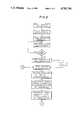
- FIG. 2The logic operation of both the method and the apparatus is shown in FIG. 2, and will be now described in combination with FIG. 3. This includes:
- the sensors Sread the data of the corresponding mechanism and send said information to the microprocessor panel SDP;
- the microprocessor CMcalculates the closing, opening, lifting and descending velocities of the corresponding mechanism and compares the actual velocity against the ideal velocity of said mechanism in the MDS card, and shows said comparison to the operator at the operator panel display OPD;
- NN+1 starting from the movement of the succeeding mechanism by following the same routine from the step wherein sensors read the data, as shown by B;
- controlshows cycle time and checks again if automatic starting is ON;
Landscapes
- Engineering & Computer Science (AREA)
- Chemical & Material Sciences (AREA)
- Physics & Mathematics (AREA)
- General Physics & Mathematics (AREA)
- Automation & Control Theory (AREA)
- Mechanical Engineering (AREA)
- Manufacturing & Machinery (AREA)
- Materials Engineering (AREA)
- Organic Chemistry (AREA)
- Re-Forming, After-Treatment, Cutting And Transporting Of Glass Products (AREA)
Abstract
Description
Claims (6)
Priority Applications (1)
| Application Number | Priority Date | Filing Date | Title |
|---|---|---|---|
| US06/888,948US4783746A (en) | 1986-07-23 | 1986-07-23 | Method and apparatus for optimizing the velocity of mechanisms and cycle time in glassware forming machines |
Applications Claiming Priority (1)
| Application Number | Priority Date | Filing Date | Title |
|---|---|---|---|
| US06/888,948US4783746A (en) | 1986-07-23 | 1986-07-23 | Method and apparatus for optimizing the velocity of mechanisms and cycle time in glassware forming machines |
Publications (1)
| Publication Number | Publication Date |
|---|---|
| US4783746Atrue US4783746A (en) | 1988-11-08 |
Family
ID=25394225
Family Applications (1)
| Application Number | Title | Priority Date | Filing Date |
|---|---|---|---|
| US06/888,948Expired - LifetimeUS4783746A (en) | 1986-07-23 | 1986-07-23 | Method and apparatus for optimizing the velocity of mechanisms and cycle time in glassware forming machines |
Country Status (1)
| Country | Link |
|---|---|
| US (1) | US4783746A (en) |
Cited By (17)
| Publication number | Priority date | Publication date | Assignee | Title |
|---|---|---|---|---|
| US5125499A (en)* | 1989-10-27 | 1992-06-30 | Vhc, Ltd. | Article transfer mechanism |
| EP0567592A4 (en)* | 1991-01-18 | 1994-04-06 | Cincinnati Milacron Inc. | |
| US5425794A (en)* | 1992-07-31 | 1995-06-20 | Emhart Glass Machinery Investments Inc. | Pneumatic position controller for I.S. machine mechanism |
| US5803945A (en)* | 1997-11-06 | 1998-09-08 | Emhart Glass Machinery Investments Inc. | Mold opening and closing mechanism for an I.S. machine |
| US5824131A (en)* | 1997-11-06 | 1998-10-20 | Emhart Glass Machinery Investments Inc. | Mold opening and closing mechanism for an I.S. machine |
| US20020184918A1 (en)* | 2001-04-10 | 2002-12-12 | Simon Jonathan S. | Control for an I.S. machine |
| US20020189293A1 (en)* | 2001-04-10 | 2002-12-19 | Simon Jonathan S. | Control for an I.S. machine |
| US20020189292A1 (en)* | 2001-04-10 | 2002-12-19 | Simon Jonathan S. | Control for an I.S. machine |
| US20020189287A1 (en)* | 2001-04-10 | 2002-12-19 | Simon Jonathan S. | Control for an I.S. machine |
| US20020189288A1 (en)* | 2001-04-10 | 2002-12-19 | Simon Jonathan S. | Control for an I. S. machine |
| US20020189294A1 (en)* | 2001-04-10 | 2002-12-19 | Simon Jonathan S. | Control for an I.S. machine |
| US20020194874A1 (en)* | 2001-04-10 | 2002-12-26 | Simon Jonathan S. | Control for an I.S. machine |
| US20020194875A1 (en)* | 2001-04-10 | 2002-12-26 | Simon Jonathan S. | Control for an I.S. machine |
| US20020194871A1 (en)* | 2001-04-10 | 2002-12-26 | Simon Jonathan S. | Control for an I.S. machine |
| EP1398677A1 (en)* | 2002-09-03 | 2004-03-17 | Futronic GmbH | Modular control system for a glass forming machine |
| EP2039661A2 (en) | 2007-09-20 | 2009-03-25 | Emhart Glass S.A. | Control for I.S. Machine |
| RU2384529C2 (en)* | 2004-11-03 | 2010-03-20 | Эмхарт Гласс С.А. | Sectional machine control system |
Citations (9)
| Publication number | Priority date | Publication date | Assignee | Title |
|---|---|---|---|---|
| US30998A (en)* | 1860-12-18 | Circular-saw gage | ||
| US4007028A (en)* | 1975-09-30 | 1977-02-08 | Reliance Electric Company | Electronically controlled glassware-forming machine |
| US4338116A (en)* | 1981-03-09 | 1982-07-06 | Owens-Illinois, Inc. | Apparatus and method for reducing mechanical dead times in the operation of a glassware forming machine |
| USRE30998E (en) | 1977-12-01 | 1982-07-20 | Owens-Illinois, Inc. | Hot gob detector for controlling a glassware forming machine |
| US4369052A (en)* | 1981-03-19 | 1983-01-18 | Owens-Illinois, Inc. | Forming supervisory control means for glassware forming machines |
| US4409013A (en)* | 1980-10-27 | 1983-10-11 | Vitro Tec Fideicomiso | 90 Degree push-out for glassware forming machines and electronic control for the same |
| US4427431A (en)* | 1981-03-30 | 1984-01-24 | Owens-Illinois, Inc. | Electronic control of a glass forming machine |
| US4615723A (en)* | 1983-05-19 | 1986-10-07 | Vitro Tec Fideicomiso | Intelligent controller for predicting and automatically compensating for variations in cycle time, in machines for forming articles of glass or other materials |
| US4623375A (en)* | 1983-11-21 | 1986-11-18 | Vitro Tec Fideicomiso | System of speed control for glass article forming machines |
- 1986
- 1986-07-23USUS06/888,948patent/US4783746A/ennot_activeExpired - Lifetime
Patent Citations (9)
| Publication number | Priority date | Publication date | Assignee | Title |
|---|---|---|---|---|
| US30998A (en)* | 1860-12-18 | Circular-saw gage | ||
| US4007028A (en)* | 1975-09-30 | 1977-02-08 | Reliance Electric Company | Electronically controlled glassware-forming machine |
| USRE30998E (en) | 1977-12-01 | 1982-07-20 | Owens-Illinois, Inc. | Hot gob detector for controlling a glassware forming machine |
| US4409013A (en)* | 1980-10-27 | 1983-10-11 | Vitro Tec Fideicomiso | 90 Degree push-out for glassware forming machines and electronic control for the same |
| US4338116A (en)* | 1981-03-09 | 1982-07-06 | Owens-Illinois, Inc. | Apparatus and method for reducing mechanical dead times in the operation of a glassware forming machine |
| US4369052A (en)* | 1981-03-19 | 1983-01-18 | Owens-Illinois, Inc. | Forming supervisory control means for glassware forming machines |
| US4427431A (en)* | 1981-03-30 | 1984-01-24 | Owens-Illinois, Inc. | Electronic control of a glass forming machine |
| US4615723A (en)* | 1983-05-19 | 1986-10-07 | Vitro Tec Fideicomiso | Intelligent controller for predicting and automatically compensating for variations in cycle time, in machines for forming articles of glass or other materials |
| US4623375A (en)* | 1983-11-21 | 1986-11-18 | Vitro Tec Fideicomiso | System of speed control for glass article forming machines |
Cited By (46)
| Publication number | Priority date | Publication date | Assignee | Title |
|---|---|---|---|---|
| US5125499A (en)* | 1989-10-27 | 1992-06-30 | Vhc, Ltd. | Article transfer mechanism |
| EP0567592A4 (en)* | 1991-01-18 | 1994-04-06 | Cincinnati Milacron Inc. | |
| US5425794A (en)* | 1992-07-31 | 1995-06-20 | Emhart Glass Machinery Investments Inc. | Pneumatic position controller for I.S. machine mechanism |
| US5803945A (en)* | 1997-11-06 | 1998-09-08 | Emhart Glass Machinery Investments Inc. | Mold opening and closing mechanism for an I.S. machine |
| US5824131A (en)* | 1997-11-06 | 1998-10-20 | Emhart Glass Machinery Investments Inc. | Mold opening and closing mechanism for an I.S. machine |
| US6009727A (en)* | 1997-11-06 | 2000-01-04 | Emhart Glass S.A. | Mold opening and closing mechanism for an I.S. machine |
| RU2286958C2 (en)* | 2001-04-10 | 2006-11-10 | Эмхарт Гласс С.А. | Control over the operations of the multi-sectional glass-forming machine |
| RU2286957C2 (en)* | 2001-04-10 | 2006-11-10 | Эмхарт Гласс С.А. | Control over the operations of the multi-sectional glass-forming machine |
| US20020189292A1 (en)* | 2001-04-10 | 2002-12-19 | Simon Jonathan S. | Control for an I.S. machine |
| US20020189287A1 (en)* | 2001-04-10 | 2002-12-19 | Simon Jonathan S. | Control for an I.S. machine |
| US20020189288A1 (en)* | 2001-04-10 | 2002-12-19 | Simon Jonathan S. | Control for an I. S. machine |
| US20020189294A1 (en)* | 2001-04-10 | 2002-12-19 | Simon Jonathan S. | Control for an I.S. machine |
| US20020194874A1 (en)* | 2001-04-10 | 2002-12-26 | Simon Jonathan S. | Control for an I.S. machine |
| US20020194875A1 (en)* | 2001-04-10 | 2002-12-26 | Simon Jonathan S. | Control for an I.S. machine |
| US20020194871A1 (en)* | 2001-04-10 | 2002-12-26 | Simon Jonathan S. | Control for an I.S. machine |
| US6604384B2 (en)* | 2001-04-10 | 2003-08-12 | Emhart Glass, S.A. | Control for an I.S. machine |
| US6604386B2 (en)* | 2001-04-10 | 2003-08-12 | Emhart Glass, S.A. | Control for an I.S. machine |
| US6604385B2 (en)* | 2001-04-10 | 2003-08-12 | Emhart Glass, S.A. | Control for an I.S. machine |
| US6604383B2 (en)* | 2001-04-10 | 2003-08-12 | Emhart Glass, S.A. | Control for an I.S. machine |
| US6606886B2 (en)* | 2001-04-10 | 2003-08-19 | Emhart Glass, S.A. | Control for an I.S. machine |
| US6705120B2 (en)* | 2001-04-10 | 2004-03-16 | Emhart Glass S.A. | Control for an I.S. machine |
| US6705119B2 (en)* | 2001-04-10 | 2004-03-16 | Emhart Glass S.A. | Control for an I. S. machine |
| DE10210276B4 (en)* | 2001-04-10 | 2017-04-27 | Emhart Glass S.A. | Control for an IS machine |
| US6711916B2 (en)* | 2001-04-10 | 2004-03-30 | Emhart Glass S.A. | Control for an I.S. machine |
| US6722158B2 (en)* | 2001-04-10 | 2004-04-20 | Emhart Glass S.A. | Control for an I.S. machine |
| CZ303506B6 (en)* | 2001-04-10 | 2012-10-24 | Emhart Glass S. A., A Swiss Corporation | Method of controlling I.S. glass forming machine with respect to optimization of glass forming process |
| RU2285672C2 (en)* | 2001-04-10 | 2006-10-20 | Эмхарт Гласс С.А. | Control of multi-section machine |
| RU2285673C2 (en)* | 2001-04-10 | 2006-10-20 | Эмхарт Гласс С.А. | Control of multi-section machine |
| RU2285671C2 (en)* | 2001-04-10 | 2006-10-20 | Эмхарт Гласс С.А. | Control of multi-section machine |
| RU2286956C2 (en)* | 2001-04-10 | 2006-11-10 | Эмхарт Гласс С.А. | Control over the operations of the multi-sectional glass-forming machine |
| RU2286955C2 (en)* | 2001-04-10 | 2006-11-10 | Эмхарт Гласс С.А. | Control over the operations of the multi-sectional glass-forming machine |
| RU2286959C2 (en)* | 2001-04-10 | 2006-11-10 | Эмхарт Гласс С.А. | Control over the operations of the multi-sectional glass-forming machine |
| RU2286960C2 (en)* | 2001-04-10 | 2006-11-10 | Эмхарт Гласс С.А. | Control over the operations of the multi-sectional glass-forming machine |
| US20020184918A1 (en)* | 2001-04-10 | 2002-12-12 | Simon Jonathan S. | Control for an I.S. machine |
| US20020189293A1 (en)* | 2001-04-10 | 2002-12-19 | Simon Jonathan S. | Control for an I.S. machine |
| CZ303158B6 (en)* | 2001-04-10 | 2012-05-09 | Emhart Glass S. A., A Swiss Corporation | Control for I.S. (individual section) glass forming machine |
| CZ302265B6 (en)* | 2001-04-10 | 2011-01-19 | Emhart Glass S. A., A Swiss Corporation | Control of glass forming I. S. machine with respect to feasible schedule in an unwrapped bottle forming process |
| CZ302264B6 (en)* | 2001-04-10 | 2011-01-19 | Emhart Glass S. A., A Swiss Corporation | Control of glass forming I. S. machine with respect to the duration of each of the thermal forming processes |
| CZ301891B6 (en)* | 2001-04-10 | 2010-07-21 | Emhart Glass S. A., A Swiss Corporation | Method of making a tool for facilitating the control of a glass-forming machine |
| CZ301890B6 (en)* | 2001-04-10 | 2010-07-21 | Emhart Glass S. A., A Swiss Corporation | Control of an I.S. (individual section) glass-forming machine |
| CZ302202B6 (en)* | 2001-04-10 | 2010-12-15 | Emhart Glass S. A., A Swiss Corporation | Control of an I.S. (individual section) glass-forming machine with respect to possible collisions of machine mechanisms |
| US7437209B2 (en) | 2002-09-03 | 2008-10-14 | Futronic Gmbh | Modular control system for a glass forming machine |
| US20040093902A1 (en)* | 2002-09-03 | 2004-05-20 | Wolfgang Lachmann | Modular control system for a glass forming machine |
| EP1398677A1 (en)* | 2002-09-03 | 2004-03-17 | Futronic GmbH | Modular control system for a glass forming machine |
| RU2384529C2 (en)* | 2004-11-03 | 2010-03-20 | Эмхарт Гласс С.А. | Sectional machine control system |
| EP2039661A2 (en) | 2007-09-20 | 2009-03-25 | Emhart Glass S.A. | Control for I.S. Machine |
Similar Documents
| Publication | Publication Date | Title |
|---|---|---|
| US4783746A (en) | Method and apparatus for optimizing the velocity of mechanisms and cycle time in glassware forming machines | |
| US4662923A (en) | Forming a gob of molten glass into a parison | |
| CA1178448A (en) | Apparatus and method for reducing mechanical dead times in the operation of a glassware forming machine | |
| US3969703A (en) | Programmable automatic controller | |
| CA1279763C (en) | Automated control of glass container manufacture | |
| US5445662A (en) | Glass container forming machine with a controller for controlling controllers | |
| JPS6125661B2 (en) | ||
| GB1603755A (en) | Control system for a cyclically operated machine | |
| EP0162458B1 (en) | Temperature control blow molding equipment in injection stretch blow molding machine | |
| EP0059576A1 (en) | A method of monitoring the closing action of a mould | |
| GB1560423A (en) | Apparatus for the manufacture of hollow bodies from a thermopolatic by the blow-moulding process | |
| JP2010511541A (en) | A method of forming a hollow container from a parison by adjusting the state with feedback when the pressure inside the parison rises due to blowing. | |
| US4453963A (en) | Method and apparatus for controlling the delivery of gobs to a section of a glassware forming machine | |
| CA2222818C (en) | Generation of lehr loader motion profile in an individual section glassware forming system | |
| US6212909B1 (en) | Synchronization of individual section machine operation to gob feed in a glassware forming system | |
| JPS5945608B2 (en) | Electronic control system for glass product forming machines | |
| US3943214A (en) | Method improvements for controlling parison length | |
| EP0059575B1 (en) | A cyclic process of forming glassware in an individual section glassware forming machine | |
| EP0802167B1 (en) | Plunger assembly | |
| US4608074A (en) | Gob distributor | |
| US3970418A (en) | Apparatus improvements for controlling parison length | |
| GB1564318A (en) | Apparatus for the manufacture of hollow bodies of a thermoplastic by blow-moulding | |
| GB1594532A (en) | Apparatus for forming glassware | |
| US4737181A (en) | Method and apparatus for controlling a pressing machine for the manufacture of glass articles | |
| EP0142320B1 (en) | Monitoring the closing action of a mould of a glassware forming machine |
Legal Events
| Date | Code | Title | Description |
|---|---|---|---|
| AS | Assignment | Owner name:VITRO TEC FIDELICOMISO, FRAMBO-YANES 2845-B, COL D Free format text:ASSIGNMENT OF ASSIGNORS INTEREST.;ASSIGNOR:CARDENAS-FRANCO, LUIS;REEL/FRAME:004608/0178 Effective date:19860721 Owner name:VITRO TEC FIDELICOMISO, FRAMBO-YANES 2845-B, COL D Free format text:ASSIGNMENT OF ASSIGNORS INTEREST;ASSIGNOR:CARDENAS-FRANCO, LUIS;REEL/FRAME:004608/0178 Effective date:19860721 | |
| STCF | Information on status: patent grant | Free format text:PATENTED CASE | |
| FPAY | Fee payment | Year of fee payment:4 | |
| FEPP | Fee payment procedure | Free format text:PAYOR NUMBER ASSIGNED (ORIGINAL EVENT CODE: ASPN); ENTITY STATUS OF PATENT OWNER: LARGE ENTITY | |
| FPAY | Fee payment | Year of fee payment:8 | |
| FPAY | Fee payment | Year of fee payment:12 | |
| AS | Assignment | Owner name:CENTRO DE TENOLOGIA VIDRIERA MONTERREY, S.A. DE C. Free format text:ASSIGNMENT OF ASSIGNORS INTEREST;ASSIGNOR:VITRO TEC FIDEICOMISO;REEL/FRAME:012973/0089 Effective date:20020228 | |
| AS | Assignment | Owner name:CENTRO DE TECNOLOGIA VIDRIERA, LTD., SWITZERLAND Free format text:CHANGE OF NAME;ASSIGNOR:CENTRO DE TECNOLOGIA VIDRIERA MONTERREY, S.A. DE C.V.;REEL/FRAME:013933/0070 Effective date:20030103 Owner name:IP TECNOLOGIA VIDRIERA, LTD., SWITZERLAND Free format text:ASSIGNMENT OF ASSIGNORS INTEREST;ASSIGNOR:CENTRO DE TECHNOLOGIA VIDRIERA, LTD.;REEL/FRAME:013922/0890 Effective date:20030103 Owner name:VITRO EUROPA, LTD., SWITZERLAND Free format text:CHANGE OF NAME;ASSIGNOR:IP TECHNOLOGIA VIDRIERA, LTD.;REEL/FRAME:013933/0657 Effective date:20030103 |