US4782833A - Bone boring instrument - Google Patents
Bone boring instrumentDownload PDFInfo
- Publication number
- US4782833A US4782833AUS07/016,587US1658787AUS4782833AUS 4782833 AUS4782833 AUS 4782833AUS 1658787 AUS1658787 AUS 1658787AUS 4782833 AUS4782833 AUS 4782833A
- Authority
- US
- United States
- Prior art keywords
- drive shaft
- trephine
- bone
- ball
- balls
- Prior art date
- Legal status (The legal status is an assumption and is not a legal conclusion. Google has not performed a legal analysis and makes no representation as to the accuracy of the status listed.)
- Expired - Fee Related
Links
- 210000000988bone and boneAnatomy0.000titleclaimsabstractdescription44
- 230000008878couplingEffects0.000claimsdescription13
- 238000010168coupling processMethods0.000claimsdescription13
- 238000005859coupling reactionMethods0.000claimsdescription13
- 238000005520cutting processMethods0.000claimsdescription3
- 238000005096rolling processMethods0.000claimsdescription2
- 230000007246mechanismEffects0.000abstractdescription4
- 238000001574biopsyMethods0.000description3
- 238000010276constructionMethods0.000description3
- 238000000034methodMethods0.000description3
- 208000020084Bone diseaseDiseases0.000description2
- 230000006835compressionEffects0.000description2
- 238000007906compressionMethods0.000description2
- 238000003780insertionMethods0.000description2
- 230000037431insertionEffects0.000description2
- 238000004519manufacturing processMethods0.000description2
- 208000029725Metabolic bone diseaseDiseases0.000description1
- 229910000831SteelInorganic materials0.000description1
- 241000347391Umbrina cirrosaSpecies0.000description1
- 238000007470bone biopsyMethods0.000description1
- 239000000428dustSubstances0.000description1
- 238000000605extractionMethods0.000description1
- 238000003306harvestingMethods0.000description1
- 230000002962histologic effectEffects0.000description1
- 238000007689inspectionMethods0.000description1
- 239000000463materialSubstances0.000description1
- 239000002184metalSubstances0.000description1
- 230000002784sclerotic effectEffects0.000description1
- 229910001220stainless steelInorganic materials0.000description1
- 239000010935stainless steelSubstances0.000description1
- 239000010959steelSubstances0.000description1
Images


Classifications
- A—HUMAN NECESSITIES
- A61—MEDICAL OR VETERINARY SCIENCE; HYGIENE
- A61B—DIAGNOSIS; SURGERY; IDENTIFICATION
- A61B10/00—Instruments for taking body samples for diagnostic purposes; Other methods or instruments for diagnosis, e.g. for vaccination diagnosis, sex determination or ovulation-period determination; Throat striking implements
- A61B10/02—Instruments for taking cell samples or for biopsy
- A61B10/0233—Pointed or sharp biopsy instruments
- A61B10/025—Pointed or sharp biopsy instruments for taking bone, bone marrow or cartilage samples
- A—HUMAN NECESSITIES
- A61—MEDICAL OR VETERINARY SCIENCE; HYGIENE
- A61B—DIAGNOSIS; SURGERY; IDENTIFICATION
- A61B17/00—Surgical instruments, devices or methods
- A61B17/16—Instruments for performing osteoclasis; Drills or chisels for bones; Trepans
- A61B17/1695—Trepans or craniotomes, i.e. specially adapted for drilling thin bones such as the skull
Definitions
- This inventionrelates to instruments for the boring of bones to remove a cylindrical section of bone for medical purposes.
- the purpose of the bone removalmay be for a biopsy, the extraction of pins, screws or other foreign bodies, or as a preparatory step for other procedures such as in the harvesting of small amounts of bone-graft material.
- the present-day instruments on the marketare available as either manual or power-operated devices.
- One of the main problems with the manual devices in use todayis that they require the surgeon to "bore” his way through bone in a procedure which requires him to re-grip the instrument after each turn. This affects the quality of the "cut” and makes the procedures cumbersome for the surgeon.
- a major problem with the power-operated devicesis that they often produce cores of bone which, on histologic inspection, are filled with bone dust and debris thereby obscurring detail.
- Another problem with prior art devicesis that they are incapable of use throughout a range of metabolic bone diseases that include brittle as well as sclerotic (hard) bone.
- the bone boring instrument of the inventionis designed to obviate the problems of the present-day prior art devices. Accordingly, the instrument of the invention is provided with a one-way drive means which allows the surgeon to comfortably oscilate his hand motion while the instrument cuts bone in one direction only. Further, by allowing the surgeon to perform the boring operation without the need of letting go or re-gripping the handle, cores of bone providing good detail can be provided. Also, the instrument in accordance with the invention is provided with a trephine engaging mechanism which allows the interchangeability of trephines so that trephines with different types of saw teeth and different sizes can be used whereby the instrument is readily adaptable for use with a range of bone diseases.
- a bone boring instrumentwhich comprises at least one trephine and a handle means for engaging and causing rotation of the trephine about its longitudinal axis for cutting a cyindrical core of bone for removal purposes.
- the handle meansincludes a body having a longitudinally extending central bore, and a drive shaft supported on the body for rotation within the central bore.
- the means for supporting the drive shaft on the bodyincludes means for providing one-way driving engagement between the body and the drive shaft so that when the body is caused to rotate in one direction relative to the drive shaft, there is caused conjoint movement of the drive shaft and body, and when the body is caused to rotate in the opposite direction relative to the drive shaft, the body can move freely relative to the drive shaft.
- a quick-release coupling meanson an extended portion of the drive shaft for releasably engaging the trephine at an enlarged head portion.
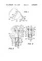
- FIG. 1is a perspective view showing the handle means of the bone boring instrument in accordance with the invention.
- FIG. 2is a longitudinal sectional view of the handle means shown in FIG. 1.
- FIG. 3is a sectional view of a detail showing the trephine engaging mechanism of the handle means in an alternate position.
- FIG. 4is a sectional view showing the handle means of FIGS. 1-3 in driving engagement with one type of trephine contained in a guide sleeve.
- FIG. 5is a sectional view taken on lines 5--5 of FIG. 4.
- FIG. 6is a view showing the handle means of FIGS. 1-3 in engagement with a second type of trephine contained in a guide sleeve.
- FIG. 7is a perspective view of another embodiment of the invention.
- FIG. 8is a sectional view of the FIG. 7 embodiment.
- FIG. 9is a sectional view taken on line 9--9 of FIG. 8.
- the bone boring instrument of the inventioncomprises a handle means 10 constructed and arranged to engage and cause rotation of a trephine about its longitudinal axis for removing a cylindrical section of bone for medical purposes.
- a trephineis a tool well known in the medical art and comprises a circular saw having an elongated strong hollow metal shaft to which is attached means for causing rotation thereof.
- a trephinefunctions to remove cylindrical sections of bone from a patient.
- One trephine 12 for use with the handle means 10is shown in FIG. 4 and comprises a hollow tubular portion 14 having circularly arranged saw teeth 16 at the distal end thereof and having an enlarged cylindrical head portion 18 at the proximal end thereof.
- the enlarged head portion 18is also hollow and is provided with a pair of aligned, diametrically opposed transverse bores 19 for use in providing engagement between the trephine 12 and the handle means 10 as will be described hereafter.
- Handle means 10comprises a body 20 having a longitudinally extending central bore 22.
- a generally circular cap 24is secured, by a threaded engagement shown in FIG. 2, at the upper end of body 20 and has formed on the exterior thereof recessed portions 26 forming an undulated rim.
- the recessed portions 26are designed to be readily gripped by the fingers of the surgeon in order to apply a rotating movement to the handle means 10 during the use of the bone boring instrument.
- Handle means 10also comprises a drive shaft 30 extending longitudinally within central bore 22.
- Meansare provided for supporting drive shaft 30 on body 20 for rotation within central bore 22.
- Such meansincludes a rolling bearing means in the form of a ball bearing 32 for rotatably supporting drive shaft 30 at the upper end thereof as viewed in FIG. 2.
- Ball bearing 32has its inner race positioned on the outer surface of drive shaft 30 and its outer race positioned on an enlarged bore portion 34 of the central bore 22.
- Ball bearing 32is held in bore portion 34 by cap 24.
- Shaft 30is provided with a pair of annular collars 31 and 33 on opposite sides of the ball bearing 32. By this arrangement, ball bearing 32 carries any axial load applied to shaft 30 during the use of the instrument.
- the instrumentcomprises means for providing one-way driving engagement between body 20 and drive shaft 30 so that when body 20 is caused to rotate in one direction relative to drive shaft 30 (clockwise as viewed from the top of FIG. 2), said last-named means causes conjoint movement of drive shaft 30 and body 20, and when body 20 is caused to rotate in the opposite direction relative to drive shaft 30 (counterclockwise as viewed from the top of FIG. 2), body 20 can move freely relative to drive shaft 30.
- the one-way drive means shown in the Drawingscomprises a roller clutch means 40 mounted in the central bore 22 with its outer surface in contact with the inner wall of the bore 22 and with the drive shaft 30 extending centrally therethrough.
- roller clutch means 40comprises a type RCB-FS clutch and bearing assembly manufactured by the Torrington Company.
- This clutch and bearing assemblycomprises an outer housing, or cage, which is engaged by a press fit with the inner wall of central bore 22, and stainless steel springs inserted within the cage to position rollers for instantaneous lockup or driving engagement with the drive shaft 30 (whereby body 20 and drive shaft 30 move conjointly).
- This type of deviceis well known in the art and is readily available.
- drive shaft 30extends from the lower end of body 20 and projects downwardly from a counterbore 36 in body 20.
- This extended end 38 of drive shaft 30has a hollow tubular configuration at the lower end thereof as is best shown in FIGS. 2 and 3.
- the quick-release coupling meanscomprises a pair of steel balls 50 contained in diametrically opposed transverse bores 52 in the hollow extended end 38 of the drive shaft 30.
- balls 50are freely movable in transverse bores 52 between a position, as shown in FIG. 2, wherein the balls 50 project into the internal bore 54 of the drive shaft 30 and a position, as shown in FIG. 3, wherein the balls 50 are clear of the internal bore 54.
- the quick-release coupling means of the inventionalso comprises a ball retainer 60 mounted on the exterior of the extended end 38 of drive shaft 30 for sliding movement between a ball retaining position shown in FIG. 2 and a ball releasing position shown in FIG. 3.
- a spring means for biasing the ball retainer 60 toward said ball retaining positioncomprising a compression coil spring 62 positioned in compression between an annular spring retainer 64 at the upper end of counterbore 36 in the lower end of body 20 and the end of a counterbore 66 in the upper end of the ball retainer 60.
- ball retainer 60is provided with a cylindrical external surface 61 adapted to be slidably received in counterbore 36 of body 20 for guiding ball retainer 60 for movement between the ball retaining and ball releasing positions shown in FIGS. 2 and 3.
- the coil spring 62is compressed.
- spring 62always maintains a bias on ball retainer 60 toward the ball retaining position of FIG. 2.
- Ball retainer 60has a reduced diameter portion 67 at its lower end. Portion 67 provides a diverging internal wall 68 in the area overlying and surrounding the balls 50 as is apparent from a consideration of FIGS. 2 and 3.
- the smaller diameter portion of wall 68is aligned with balls 50 and comes into contact with balls 50 to maintain them in their inward position whereby balls 50 project into internal bore 54 of drive shaft 30.
- the larger diameter portion of wall 68is aligned with balls 50 to allow the balls 50 to move radially out of internal bore 54, as is apparent from a consideration of FIG. 3.
- ball retainer 60is moved manually to the ball releasing position of FIG. 3 and a trephine, such as trephine 12, is inserted with its enlarged cyindrical head portion 18 extending within internal bore 54.
- a trephinesuch as trephine 12
- the insertion of the enlarged head portion 18is stopped at a small annular stop 53 formed at the upper end of internal bore 54 (see FIG. 4 which shows trephine 12 in the fully inserted position).
- the ball retainer 60When it is desired to remove the trephine 12, the ball retainer 60 is pulled manually upwardly from the position shown in FIGS. 2 and 4 to the position of FIG. 3 allowing the balls 50 to move outwardly in response to a separating movement applied to the trephine 12.
- the complete bone boring instrument as used by a surgeonis shown in FIG. 4.
- the instrumentcomprises the handle means 10 and a trephine 12 coupled on the extended end thereof by the quick-release coupling means as described above.
- the trephine 12is positioned within a guide sleeve means 70, which comprises a body 72 having an elongated tube 74 mounted therein.
- the body 72has a concave portion 76 adapted to be held by the fingers of one hand of the surgeon while the surgeon holds the handle means 10 in his other hand.
- the guide sleeve means 70has the tubular portion 14 of a trephine 12 slidably and rotatably held within tube 74 as shown in FIG. 4 and provides a guide for the trephine 12 as the surgeon performs the bone boring operation.
- FIG. 6there is shown another trephine 12' similar to the trephine 12 whereby corresponding parts have been given the same reference numerals with primes added.
- the trephine 12'is adapted for use with the handle means 10 and comprises a hollow tubular portion 14' having circularly arranged saw teeth 16' at the distal end thereof and having an enlarged cylindrical head portion 18' at the proximal end thereof.
- Head portion 18'is hollow and has a pair of aligned, diametrically opposed transverse bores 19' for use in providing with engagement between the trephine 12' and the balls 50 of the handle means 10 as described above.
- Trephine 12'is essentially identical with trephine 12 except that the tubular portion 14' and the circular teeth 16' are of a larger diameter.
- Trephine 12'is provided with an associated guide sleeve means 70' similar to guide means 70 for use with trephine 12.
- the guide sleeve means 70'is provided with a body 72' having a finger receivable concave portion 76' and an elongated tube 74' adapted to slidably receive the tubular portion 14' of trephine 12' for guiding the same.
- the head portion 18' and the bores 19' of trephine 12'are identical to the corresponding head portion 18 and bores 19 of trephine 12 so as to be interchangeably engageable with the quick-release coupling means of the handle means 10 as described above.
- the commercially available bone boring instrument in accordance with the inventionis provided with many trephines and associated guide sleeve means including different types of saw teeth and different sizes whereby the instrument is readily adaptable for use with a range of bone diseases.
- the surgeoncan hold the handle means 10 in his right hand while holding a trephine containing guide sleeve means in his left hand with the trephine's distal end saw teeth 16 exposed for contact with the patient.
- the surgeoncan comfortably oscillate his right hand and handle means 10 in a clockwise and counterclockwise motion whereby the instrument will cut bone during the clockwise rotation only.
- the trephinewill not be moved, but will remain stationary in engagement with the bone of the patient.
- FIGS. 7-9show an embodiment of the invention comprising a modified trephine, and a modified extended end of the handle means cooperating therewith, whereby there is provided easier alignment and better torque capability between the handle means and the trephine.
- a trephine 82similar in construction to trephine 12 and comprising a hollow tubular portion 84 similar to the tubular portion 14 of trephine 12.
- tubular portion 14has circularly arranged teeth 86 at the distal end thereof and has an enlarged head portion 88 at the proximal end thereof.
- Head portion 88is similar to head portion 18 of trephine 12 except that it is not provided with any transverse bores. Instead, there is provided an adapter 90 which is welded to the head of trephine 82.
- Adapter 90has a hollow tubular construction including an enlarged diameter lower portion 91 adapted to receive the head 88 of trephine 82.
- the adapter 90is welded to the head 38 at the overlapping cylindrical portions of head 88 and lower portion 91 to form a unitary structure.
- Adapter 90is provided with an upper hollow tubular portion 93 provided with a pair of aligned, diametrically opposed bores 89 for use in providing engagement between the trephine 82 and the handle means 10.
- the bores 89are located in the same manner as the bores 19 of trephine 12 and accordingly are adapted to cooperate with the balls 50 of the quick-release coupling means on the extended end 38 of the drive shaft 30 of handle means 10 in the manner described above with respect to the emodiment shown in FIGS. 1-6.
- Adapter 90is provided with a laterally extending key portion 92 providing a pair of spaced apart parallel walls 95.
- the extended end 38 of the drive shaft 30is provided with a generally rectangular bottom opening 38' adapted to receive key portion 92 with slidable contact with the parallel sidewalls 95 thereof.
- trephine 82is releasably engageable with the quick release coupling means on the extended end of drive shaft 30.
- the tubular portion 93is inserted upwardly through the bottom opening 38' into the bore 54 in extended end 38 up to stop 53 with key portion 92 being oriented to slide into the rectangular opening 38' with the sidewalls 95 in engagement with the cooperating sidewall portions of opening 38' to a position as shown in FIG. 8. In this position, bores 89 are aligned with balls 50 which move into engagement therewith.
- the insertion and removal of the trephine 82is the same as that described above with respect to trephine 12, the only difference being that the cooperation between the walls 95 and opening 38' orient the trephine 82 to a desired relative position with respect to extended end 38 such that the openings 89 are aligned with the balls 50 as the trephine is moved upwardly into the position as shown in FIG. 8. This achieves an easier alignment of the trephine 82 in the handle means 10.
- the cooperation of the walls of the opening 38' with the sidewalls 95provide an improved torque capability as compared with the embodiments shown in FIGS. 1-6.
Landscapes
- Health & Medical Sciences (AREA)
- Life Sciences & Earth Sciences (AREA)
- Surgery (AREA)
- Public Health (AREA)
- Veterinary Medicine (AREA)
- General Health & Medical Sciences (AREA)
- Orthopedic Medicine & Surgery (AREA)
- Engineering & Computer Science (AREA)
- Biomedical Technology (AREA)
- Heart & Thoracic Surgery (AREA)
- Medical Informatics (AREA)
- Molecular Biology (AREA)
- Animal Behavior & Ethology (AREA)
- Immunology (AREA)
- Pathology (AREA)
- Hematology (AREA)
- Rheumatology (AREA)
- Neurosurgery (AREA)
- Dentistry (AREA)
- Oral & Maxillofacial Surgery (AREA)
- Nuclear Medicine, Radiotherapy & Molecular Imaging (AREA)
- Surgical Instruments (AREA)
Abstract
Description
Claims (11)
Priority Applications (1)
| Application Number | Priority Date | Filing Date | Title |
|---|---|---|---|
| US07/016,587US4782833A (en) | 1987-02-19 | 1987-02-19 | Bone boring instrument |
Applications Claiming Priority (1)
| Application Number | Priority Date | Filing Date | Title |
|---|---|---|---|
| US07/016,587US4782833A (en) | 1987-02-19 | 1987-02-19 | Bone boring instrument |
Publications (1)
| Publication Number | Publication Date |
|---|---|
| US4782833Atrue US4782833A (en) | 1988-11-08 |
Family
ID=21777917
Family Applications (1)
| Application Number | Title | Priority Date | Filing Date |
|---|---|---|---|
| US07/016,587Expired - Fee RelatedUS4782833A (en) | 1987-02-19 | 1987-02-19 | Bone boring instrument |
Country Status (1)
| Country | Link |
|---|---|
| US (1) | US4782833A (en) |
Cited By (93)
| Publication number | Priority date | Publication date | Assignee | Title |
|---|---|---|---|---|
| US5015255A (en)* | 1989-05-10 | 1991-05-14 | Spine-Tech, Inc. | Spinal stabilization method |
| US5057112A (en)* | 1990-01-04 | 1991-10-15 | Intermedics Orthopedics, Inc. | Pneumatically powered orthopedic broach |
| US5152763A (en)* | 1991-04-02 | 1992-10-06 | Johnson Lanny L | Method for grafting bone |
| US5217497A (en)* | 1990-07-04 | 1993-06-08 | Mehdian Seyed M H | Apparatus for use in the treatment of spinal disorders |
| US5269795A (en)* | 1991-07-03 | 1993-12-14 | Arnott Eric J | Trephine device for removing anterior epithelial cells from corneal surfaces |
| US5312408A (en)* | 1992-10-21 | 1994-05-17 | Brown Byron L | Apparatus and method of cutting and suctioning the medullary canal of long bones prior to insertion of an endoprosthesis |
| US5346497A (en)* | 1992-07-15 | 1994-09-13 | The University Of Miami | Surgical cutting head with asymmetrical cutting notch |
| US5372583A (en)* | 1992-11-25 | 1994-12-13 | Cardiopulmonary Specialities, Inc. | Bone marrow infuser and method of use |
| US5423823A (en)* | 1993-02-18 | 1995-06-13 | Arthrex Inc. | Coring reamer |
| US5443471A (en)* | 1993-02-16 | 1995-08-22 | Howmedica, Inc. | Quick release handle assembly |
| US5462548A (en)* | 1992-07-06 | 1995-10-31 | Pappas; Michael J. | Acetabular reamer |
| EP0677275A3 (en)* | 1994-03-17 | 1995-11-22 | Terumo Corp | |
| US5489308A (en)* | 1989-07-06 | 1996-02-06 | Spine-Tech, Inc. | Spinal implant |
| US5603716A (en)* | 1995-02-16 | 1997-02-18 | Arthrex Inc. | Method of ligament reconstruction using double socket graft placement and fixation |
| US5613972A (en)* | 1992-07-15 | 1997-03-25 | The University Of Miami | Surgical cutting heads with curled cutting wings |
| US5632747A (en)* | 1995-03-15 | 1997-05-27 | Osteotech, Inc. | Bone dowel cutter |
| US5720749A (en)* | 1996-03-18 | 1998-02-24 | Snap-On Technologies, Inc. | Integral reamer apparatus with guide counterbores in female press-fitted parts |
| US5782835A (en)* | 1995-03-07 | 1998-07-21 | Innovasive Devices, Inc. | Apparatus and methods for articular cartilage defect repair |
| USD397437S (en) | 1993-08-23 | 1998-08-25 | Hall Surgical | Bone milling burr shaft |
| US5865834A (en)* | 1991-12-13 | 1999-02-02 | Mcguire; David A. | Coring reamer |
| US5885293A (en)* | 1997-03-03 | 1999-03-23 | Innovasive Devices, Inc. | Apparatus and method for cutting a surface at a repeatable angle |
| US5895427A (en)* | 1989-07-06 | 1999-04-20 | Sulzer Spine-Tech Inc. | Method for spinal fixation |
| US5919196A (en)* | 1995-02-16 | 1999-07-06 | Arthrex, Inc. | Method and apparatus for osteochondral autograft transplantation |
| US5954671A (en)* | 1998-04-20 | 1999-09-21 | O'neill; Michael J. | Bone harvesting method and apparatus |
| US5961522A (en)* | 1997-11-10 | 1999-10-05 | Mehdizadeh; Hamid M. | Laminectomy chisel and guide apparatus |
| US6283971B1 (en) | 2000-04-25 | 2001-09-04 | Randy S. Temeles | Expandable acetabular reaming system |
| US6592588B1 (en) | 1995-02-16 | 2003-07-15 | Arthrex, Inc. | Apparatus for osteochondral autograft transplantation |
| US20040059317A1 (en)* | 2000-12-23 | 2004-03-25 | Aesculap Ag & Co. Kg | Drilling tool for a surgical drill |
| US20060173476A1 (en)* | 2005-02-02 | 2006-08-03 | Gino Bradica | Coring device for preserving living tissue |
| US20070032742A1 (en)* | 2005-08-05 | 2007-02-08 | Monson Gavin M | Biopsy Device with Vacuum Assisted Bleeding Control |
| US20070032743A1 (en)* | 2005-08-05 | 2007-02-08 | Hibner John A | Vacuum Syringe Assisted Biopsy Device |
| US7201775B2 (en) | 2002-09-24 | 2007-04-10 | Bogomir Gorensek | Stabilizing device for intervertebral disc, and methods thereof |
| JP2007117720A (en)* | 2005-10-26 | 2007-05-17 | Joimax Gmbh | Facet joint reamer |
| US20070123892A1 (en)* | 2005-10-26 | 2007-05-31 | Joimax Gmbh | Facet joint reamer |
| US20070135917A1 (en)* | 2005-10-26 | 2007-06-14 | Malinin Theodore I | Instrumentation for the preparation and transplantation of osteochondral allografts |
| US20070135731A1 (en)* | 2005-12-09 | 2007-06-14 | Ward Richard D | Dermal incisor |
| US20070173877A1 (en)* | 2004-06-03 | 2007-07-26 | Matthias Steinwachs | Device For Punching Out Tissue Areas From Bone |
| US20070239067A1 (en)* | 2005-08-05 | 2007-10-11 | Hibner John A | Tissue Sample Revolver Drum Biopsy Device |
| US7285121B2 (en) | 2001-11-05 | 2007-10-23 | Warsaw Orthopedic, Inc. | Devices and methods for the correction and treatment of spinal deformities |
| US20070276506A1 (en)* | 2006-05-25 | 2007-11-29 | Biomet Manufacturing Corp. | Demineralized osteochondral plug |
| US20080004545A1 (en)* | 2005-08-05 | 2008-01-03 | Garrison William A | Trigger Fired Radial Plate Specimen Retrieval Biopsy Instrument |
| US20090093853A1 (en)* | 2007-10-05 | 2009-04-09 | Biomet Manufacturing Corp. | System For Forming A Tendon-Bone Graft |
| US20090112230A1 (en)* | 2007-10-31 | 2009-04-30 | Kabushiki Kaisha Toshiba | Manipulator |
| US20090112229A1 (en)* | 2007-10-31 | 2009-04-30 | Terumo Kabushiki Kaisha | Manipulator for medical use |
| US20090131817A1 (en)* | 2007-11-20 | 2009-05-21 | Speeg Trevor W V | Deployment device interface for biopsy device |
| US7563282B2 (en) | 1999-08-18 | 2009-07-21 | Intrinsic Therapeutics, Inc. | Method of supporting nucleus pulposus |
| US20090222052A1 (en)* | 2007-10-05 | 2009-09-03 | Biomet Manufacturing Corp. | System For Forming A Tendon-Bone Graft |
| US7662185B2 (en) | 1999-12-30 | 2010-02-16 | Osteotech, Inc. | Intervertebral implants |
| US20100113971A1 (en)* | 2005-08-05 | 2010-05-06 | Ethicon Endo-Surgery, Inc. | Biopsy Device with Translating Valve Mechanism |
| US7726002B2 (en) | 2001-12-05 | 2010-06-01 | Osteotech, Inc. | Processes for making spinal intervertebral implant, interconnections for such implant |
| US7780708B2 (en) | 2000-10-20 | 2010-08-24 | Osteotech, Inc. | Implant retaining device |
| US20100228146A1 (en)* | 2004-09-29 | 2010-09-09 | Hibner John A | Biopsy Device With Integral vacuum Assist And Tissue Sample And Fluid Capturing Canister |
| US7806835B2 (en) | 2007-11-20 | 2010-10-05 | Devicor Medical Products, Inc. | Biopsy device with sharps reduction feature |
| US7858038B2 (en) | 2007-11-20 | 2010-12-28 | Devicor Medical Products, Inc. | Biopsy device with illuminated tissue holder |
| US7896817B2 (en) | 2005-08-05 | 2011-03-01 | Devicor Medical Products, Inc. | Biopsy device with manually rotated sample barrel |
| US7931689B2 (en) | 2000-02-28 | 2011-04-26 | Spineology Inc. | Method and apparatus for treating a vertebral body |
| US7938786B2 (en) | 2006-12-13 | 2011-05-10 | Devicor Medical Products, Inc. | Vacuum timing algorithm for biopsy device |
| US7981049B2 (en) | 2006-12-13 | 2011-07-19 | Devicor Medical Products, Inc. | Engagement interface for biopsy system vacuum module |
| US8052616B2 (en) | 2007-11-20 | 2011-11-08 | Devicor Medical Products, Inc. | Biopsy device with fine pitch drive train |
| US8145319B1 (en) | 2005-10-11 | 2012-03-27 | Ebi, Llc | Methods and devices for treatment of osteonecrosis of the femoral head with core decompression |
| US8162967B1 (en) | 2003-10-16 | 2012-04-24 | Biomet Sports Medicine Llc | Method and apparatus for coring and reaming of bone |
| US8251916B2 (en) | 2006-12-13 | 2012-08-28 | Devicor Medical Products, Inc. | Revolving tissue sample holder for biopsy device |
| US8287538B2 (en) | 2008-01-14 | 2012-10-16 | Conventus Orthopaedics, Inc. | Apparatus and methods for fracture repair |
| US8333985B2 (en) | 2004-01-27 | 2012-12-18 | Warsaw Orthopedic, Inc. | Non-glycerol stabilized bone graft |
| US8372157B2 (en) | 2007-02-12 | 2013-02-12 | Warsaw Orthopedic, Inc. | Joint revision implant |
| US8454531B2 (en) | 2007-11-20 | 2013-06-04 | Devicor Medical Products, Inc. | Icon-based user interface on biopsy system control module |
| US8480595B2 (en) | 2006-12-13 | 2013-07-09 | Devicor Medical Products, Inc. | Biopsy device with motorized needle cocking |
| US8641718B2 (en) | 2010-10-19 | 2014-02-04 | Biomet Manufacturing, Llc | Method and apparatus for harvesting cartilage for treatment of a cartilage defect |
| US8702623B2 (en) | 2008-12-18 | 2014-04-22 | Devicor Medical Products, Inc. | Biopsy device with discrete tissue chambers |
| US8906022B2 (en) | 2010-03-08 | 2014-12-09 | Conventus Orthopaedics, Inc. | Apparatus and methods for securing a bone implant |
| US8961518B2 (en) | 2010-01-20 | 2015-02-24 | Conventus Orthopaedics, Inc. | Apparatus and methods for bone access and cavity preparation |
| US9039634B2 (en) | 2007-11-20 | 2015-05-26 | Devicor Medical Products, Inc. | Biopsy device tissue sample holder rotation control |
| US9095326B2 (en) | 2006-12-13 | 2015-08-04 | Devicor Medical Products, Inc. | Biopsy system with vacuum control module |
| USRE46135E1 (en) | 2005-08-05 | 2016-09-06 | Devicor Medical Products, Inc. | Vacuum syringe assisted biopsy device |
| CN106963522A (en)* | 2017-04-21 | 2017-07-21 | 中国人民解放军第二军医大学第二附属医院 | A kind of micro-wound pressure-reduced emerging system of posterolateral lumbar spinal |
| US9730739B2 (en) | 2010-01-15 | 2017-08-15 | Conventus Orthopaedics, Inc. | Rotary-rigid orthopaedic rod |
| US10022132B2 (en) | 2013-12-12 | 2018-07-17 | Conventus Orthopaedics, Inc. | Tissue displacement tools and methods |
| US20180256201A1 (en)* | 2014-02-21 | 2018-09-13 | Surgentec, Llc | Handles for needle assemblies |
| CN108601631A (en)* | 2016-01-20 | 2018-09-28 | 金煐载 | surgical hand drill |
| US10485558B1 (en)* | 2015-07-31 | 2019-11-26 | Joshua Cook | Apparatus and method for harvesting bone |
| US10595831B2 (en) | 2012-05-30 | 2020-03-24 | Devicor Medical Products, Inc. | Control for biopsy device |
| US10918426B2 (en) | 2017-07-04 | 2021-02-16 | Conventus Orthopaedics, Inc. | Apparatus and methods for treatment of a bone |
| US20210045755A1 (en)* | 2013-03-15 | 2021-02-18 | Teleflex Life Sciences Limited | Intraosseous device handles, systems, and methods |
| CN112384157A (en)* | 2018-02-20 | 2021-02-19 | 派柏阿克塞斯有限责任公司 | Drilling apparatus and associated method |
| US11179141B2 (en) | 2006-12-13 | 2021-11-23 | Devicor Medical Products, Inc. | Biopsy system |
| US11317934B2 (en)* | 2016-09-07 | 2022-05-03 | Vertos Medical, Inc. | Percutaneous lateral recess resection methods and instruments |
| US11523834B1 (en) | 2022-06-20 | 2022-12-13 | University Of Utah Research Foundation | Cartilage and bone harvest and delivery system and methods |
| US11596419B2 (en) | 2017-03-09 | 2023-03-07 | Flower Orthopedics Corporation | Plating depth gauge and countersink instrument |
| US11660194B1 (en) | 2022-06-20 | 2023-05-30 | University Of Utah Research Foundation | Cartilage and bone harvest and delivery system and methods |
| US12023047B1 (en) | 2023-07-14 | 2024-07-02 | University Of Utah Research Foundation | Cannulated trephine |
| US12089972B2 (en) | 2006-09-12 | 2024-09-17 | Teleflex Life Sciences Limited | Apparatus and methods for biopsy and aspiration of bone marrow |
| US12324572B2 (en) | 2022-06-16 | 2025-06-10 | Vertos Medical, Inc. | Integrated instrument assembly |
| US12376881B2 (en) | 2017-03-07 | 2025-08-05 | Piper Access, Llc | Safety shields for elongated instruments and related systems and methods |
Citations (4)
| Publication number | Priority date | Publication date | Assignee | Title |
|---|---|---|---|---|
| US3835858A (en)* | 1972-09-05 | 1974-09-17 | Weck & Co Inc Edward | Surgical air drill |
| US4235595A (en)* | 1977-05-31 | 1980-11-25 | Arnegger Richard E | Handpiece with continuous shaft and bell rotor |
| US4314577A (en)* | 1979-07-09 | 1982-02-09 | Brister Beryle D | Installation, hydrostatic testing, repair and modification of large diameter fluid transmission lines |
| US4600006A (en)* | 1984-01-31 | 1986-07-15 | Baker John W | Cranial perforator |
- 1987
- 1987-02-19USUS07/016,587patent/US4782833A/ennot_activeExpired - Fee Related
Patent Citations (4)
| Publication number | Priority date | Publication date | Assignee | Title |
|---|---|---|---|---|
| US3835858A (en)* | 1972-09-05 | 1974-09-17 | Weck & Co Inc Edward | Surgical air drill |
| US4235595A (en)* | 1977-05-31 | 1980-11-25 | Arnegger Richard E | Handpiece with continuous shaft and bell rotor |
| US4314577A (en)* | 1979-07-09 | 1982-02-09 | Brister Beryle D | Installation, hydrostatic testing, repair and modification of large diameter fluid transmission lines |
| US4600006A (en)* | 1984-01-31 | 1986-07-15 | Baker John W | Cranial perforator |
Cited By (175)
| Publication number | Priority date | Publication date | Assignee | Title |
|---|---|---|---|---|
| US5062845A (en)* | 1989-05-10 | 1991-11-05 | Spine-Tech, Inc. | Method of making an intervertebral reamer |
| US5015255A (en)* | 1989-05-10 | 1991-05-14 | Spine-Tech, Inc. | Spinal stabilization method |
| US6391058B1 (en) | 1989-07-06 | 2002-05-21 | Sulzer Spine-Tech Inc. | Threaded spinal implant with convex trailing surface |
| US5895427A (en)* | 1989-07-06 | 1999-04-20 | Sulzer Spine-Tech Inc. | Method for spinal fixation |
| US6287343B1 (en) | 1989-07-06 | 2001-09-11 | Sulzer Spine-Tech, Inc. | Threaded spinal implant with bone ingrowth openings |
| US6149686A (en)* | 1989-07-06 | 2000-11-21 | Sulzer Spine-Tech Inc. | Threaded spinal implant with bone ingrowth openings |
| US5489308A (en)* | 1989-07-06 | 1996-02-06 | Spine-Tech, Inc. | Spinal implant |
| US5057112A (en)* | 1990-01-04 | 1991-10-15 | Intermedics Orthopedics, Inc. | Pneumatically powered orthopedic broach |
| US5217497A (en)* | 1990-07-04 | 1993-06-08 | Mehdian Seyed M H | Apparatus for use in the treatment of spinal disorders |
| US5152763A (en)* | 1991-04-02 | 1992-10-06 | Johnson Lanny L | Method for grafting bone |
| US5269795A (en)* | 1991-07-03 | 1993-12-14 | Arnott Eric J | Trephine device for removing anterior epithelial cells from corneal surfaces |
| US5632757A (en)* | 1991-07-03 | 1997-05-27 | Arnott; Eric J. | Trephine device for removing anterior epithelial cells from corneal surface |
| US5865834A (en)* | 1991-12-13 | 1999-02-02 | Mcguire; David A. | Coring reamer |
| US5462548A (en)* | 1992-07-06 | 1995-10-31 | Pappas; Michael J. | Acetabular reamer |
| US5613972A (en)* | 1992-07-15 | 1997-03-25 | The University Of Miami | Surgical cutting heads with curled cutting wings |
| US5346497A (en)* | 1992-07-15 | 1994-09-13 | The University Of Miami | Surgical cutting head with asymmetrical cutting notch |
| US5312408A (en)* | 1992-10-21 | 1994-05-17 | Brown Byron L | Apparatus and method of cutting and suctioning the medullary canal of long bones prior to insertion of an endoprosthesis |
| US5372583A (en)* | 1992-11-25 | 1994-12-13 | Cardiopulmonary Specialities, Inc. | Bone marrow infuser and method of use |
| US5443471A (en)* | 1993-02-16 | 1995-08-22 | Howmedica, Inc. | Quick release handle assembly |
| US5423823A (en)* | 1993-02-18 | 1995-06-13 | Arthrex Inc. | Coring reamer |
| USD397437S (en) | 1993-08-23 | 1998-08-25 | Hall Surgical | Bone milling burr shaft |
| EP0677275A3 (en)* | 1994-03-17 | 1995-11-22 | Terumo Corp | |
| US5649955A (en)* | 1994-03-17 | 1997-07-22 | Terumo Kabushiki Kaisha | Surgical instrument |
| US5785714A (en)* | 1995-02-16 | 1998-07-28 | Arthrex, Inc. | Method of ACL reconstruction using double socket graft placement and fixation |
| US6592588B1 (en) | 1995-02-16 | 2003-07-15 | Arthrex, Inc. | Apparatus for osteochondral autograft transplantation |
| US5603716A (en)* | 1995-02-16 | 1997-02-18 | Arthrex Inc. | Method of ligament reconstruction using double socket graft placement and fixation |
| US5919196A (en)* | 1995-02-16 | 1999-07-06 | Arthrex, Inc. | Method and apparatus for osteochondral autograft transplantation |
| US6017348A (en)* | 1995-03-07 | 2000-01-25 | Innovasive Devices, Inc. | Apparatus and methods for articular cartilage defect repair |
| US5782835A (en)* | 1995-03-07 | 1998-07-21 | Innovasive Devices, Inc. | Apparatus and methods for articular cartilage defect repair |
| US5928238A (en)* | 1995-03-15 | 1999-07-27 | Osteotech, Inc. | Bone dowel cutter |
| US5632747A (en)* | 1995-03-15 | 1997-05-27 | Osteotech, Inc. | Bone dowel cutter |
| US5720749A (en)* | 1996-03-18 | 1998-02-24 | Snap-On Technologies, Inc. | Integral reamer apparatus with guide counterbores in female press-fitted parts |
| US5885293A (en)* | 1997-03-03 | 1999-03-23 | Innovasive Devices, Inc. | Apparatus and method for cutting a surface at a repeatable angle |
| US5961522A (en)* | 1997-11-10 | 1999-10-05 | Mehdizadeh; Hamid M. | Laminectomy chisel and guide apparatus |
| USRE40796E1 (en) | 1998-04-20 | 2009-06-23 | Paradigm Biodevices, Inc. | Bone harvesting method and apparatus |
| US5954671A (en)* | 1998-04-20 | 1999-09-21 | O'neill; Michael J. | Bone harvesting method and apparatus |
| US7563282B2 (en) | 1999-08-18 | 2009-07-21 | Intrinsic Therapeutics, Inc. | Method of supporting nucleus pulposus |
| US7662185B2 (en) | 1999-12-30 | 2010-02-16 | Osteotech, Inc. | Intervertebral implants |
| US7931689B2 (en) | 2000-02-28 | 2011-04-26 | Spineology Inc. | Method and apparatus for treating a vertebral body |
| US6283971B1 (en) | 2000-04-25 | 2001-09-04 | Randy S. Temeles | Expandable acetabular reaming system |
| US7780708B2 (en) | 2000-10-20 | 2010-08-24 | Osteotech, Inc. | Implant retaining device |
| US8672980B2 (en) | 2000-10-20 | 2014-03-18 | Warsaw Orthopedic, Inc. | Implant retaining device |
| US20040059317A1 (en)* | 2000-12-23 | 2004-03-25 | Aesculap Ag & Co. Kg | Drilling tool for a surgical drill |
| US7285121B2 (en) | 2001-11-05 | 2007-10-23 | Warsaw Orthopedic, Inc. | Devices and methods for the correction and treatment of spinal deformities |
| US7726002B2 (en) | 2001-12-05 | 2010-06-01 | Osteotech, Inc. | Processes for making spinal intervertebral implant, interconnections for such implant |
| US7201775B2 (en) | 2002-09-24 | 2007-04-10 | Bogomir Gorensek | Stabilizing device for intervertebral disc, and methods thereof |
| US8162967B1 (en) | 2003-10-16 | 2012-04-24 | Biomet Sports Medicine Llc | Method and apparatus for coring and reaming of bone |
| US8333985B2 (en) | 2004-01-27 | 2012-12-18 | Warsaw Orthopedic, Inc. | Non-glycerol stabilized bone graft |
| US8617162B2 (en)* | 2004-06-03 | 2013-12-31 | Karl Storz Gmbh & Co. Kg | Device for punching out tissue areas from bone |
| US20070173877A1 (en)* | 2004-06-03 | 2007-07-26 | Matthias Steinwachs | Device For Punching Out Tissue Areas From Bone |
| US9757100B2 (en) | 2004-09-29 | 2017-09-12 | Devicor Medical Products, Inc. | Biopsy device with integral vacuum assist and tissue sample and fluid capturing canister |
| US9468425B2 (en) | 2004-09-29 | 2016-10-18 | Devicor Medical Products, Inc. | Biopsy device with integral vacuum assist and tissue sample and fluid capturing canister |
| US20100228146A1 (en)* | 2004-09-29 | 2010-09-09 | Hibner John A | Biopsy Device With Integral vacuum Assist And Tissue Sample And Fluid Capturing Canister |
| US8956306B2 (en) | 2004-09-29 | 2015-02-17 | Devicor Medical Products, Inc. | Biopsy device with integral vacuum assist and tissue sample and fluid capturing canister |
| US9265485B2 (en) | 2004-09-29 | 2016-02-23 | Devicor Medical Products, Inc. | Biopsy device with integral vacuum assist and tissue sample and fluid capturing canister |
| US9782196B2 (en) | 2005-02-02 | 2017-10-10 | Dsm Ip Assets B.V. | Coring device for preserving living tissue |
| US8672941B2 (en) | 2005-02-02 | 2014-03-18 | Kensey Nash Bvf Technology Llc | Coring device for preserving living tissue |
| US20060217753A1 (en)* | 2005-02-02 | 2006-09-28 | Gino Bradica | Coring device for preserving living tissue |
| WO2006083471A2 (en) | 2005-02-02 | 2006-08-10 | Kensey Nash Corporation | Coring device for preserving living tissue |
| US20060173476A1 (en)* | 2005-02-02 | 2006-08-03 | Gino Bradica | Coring device for preserving living tissue |
| US11224412B2 (en) | 2005-08-05 | 2022-01-18 | Devicor Medical Products, Inc. | Biopsy device with translating valve member |
| US9005136B2 (en) | 2005-08-05 | 2015-04-14 | Devicor Medical Products, Inc. | Biopsy device with vacuum assisted bleeding control |
| US8979769B2 (en) | 2005-08-05 | 2015-03-17 | Devicor Medical Products, Inc. | Biopsy device with vacuum assisted bleeding control |
| US20150141867A1 (en)* | 2005-08-05 | 2015-05-21 | Devicor Medical Products, Inc. | Biopsy device with translating valve member |
| US9414814B2 (en) | 2005-08-05 | 2016-08-16 | Devicor Medical Products, Inc. | Biopsy device with rotatable tissue sample holder |
| US8911381B2 (en) | 2005-08-05 | 2014-12-16 | Devicor Medical Products, Inc. | Biopsy device with translating valve member |
| US20080004545A1 (en)* | 2005-08-05 | 2008-01-03 | Garrison William A | Trigger Fired Radial Plate Specimen Retrieval Biopsy Instrument |
| US20100113973A1 (en)* | 2005-08-05 | 2010-05-06 | Ethicon Endo-Surgery, Inc. | Biopsy Device with Rotatable Tissue Sample Holder |
| US20100113971A1 (en)* | 2005-08-05 | 2010-05-06 | Ethicon Endo-Surgery, Inc. | Biopsy Device with Translating Valve Mechanism |
| WO2007019152A3 (en)* | 2005-08-05 | 2008-01-03 | Ethicon Endo Surgery Inc | Biopsy device with replaceable probe and incorporating vibration insertion assist and static vacuum source sample stacking retrieval |
| US8905943B2 (en) | 2005-08-05 | 2014-12-09 | Devicor Medical Products, Inc. | Biopsy device with rotatable tissue sample holder |
| USRE46135E1 (en) | 2005-08-05 | 2016-09-06 | Devicor Medical Products, Inc. | Vacuum syringe assisted biopsy device |
| US20070239067A1 (en)* | 2005-08-05 | 2007-10-11 | Hibner John A | Tissue Sample Revolver Drum Biopsy Device |
| US9901327B2 (en)* | 2005-08-05 | 2018-02-27 | Devicor Medical Products, Inc. | Biopsy device with translating valve member |
| US7828748B2 (en) | 2005-08-05 | 2010-11-09 | Devicor Medical Products, Inc. | Vacuum syringe assisted biopsy device |
| US7854707B2 (en) | 2005-08-05 | 2010-12-21 | Devicor Medical Products, Inc. | Tissue sample revolver drum biopsy device |
| US9907542B2 (en) | 2005-08-05 | 2018-03-06 | Devicor Medical Products, Inc. | Biopsy device with translating valve member |
| US7867173B2 (en) | 2005-08-05 | 2011-01-11 | Devicor Medical Products, Inc. | Biopsy device with replaceable probe and incorporating vibration insertion assist and static vacuum source sample stacking retrieval |
| US7896817B2 (en) | 2005-08-05 | 2011-03-01 | Devicor Medical Products, Inc. | Biopsy device with manually rotated sample barrel |
| US20110071433A1 (en)* | 2005-08-05 | 2011-03-24 | Devicor Medical Products, Inc. | Biopsy device with translating valve member |
| US7918804B2 (en) | 2005-08-05 | 2011-04-05 | Devicor Medical Products, Inc. | Biopsy device with vacuum assisted bleeding control |
| US9968339B2 (en) | 2005-08-05 | 2018-05-15 | Devicor Medical Products, Inc. | Biopsy device with rotatable tissue sample holder |
| US8241226B2 (en) | 2005-08-05 | 2012-08-14 | Devicor Medical Products, Inc. | Biopsy device with rotatable tissue sample holder |
| US8568335B2 (en) | 2005-08-05 | 2013-10-29 | Devicor Medical Products, Inc. | Biopsy device with vacuum assisted bleeding control |
| US8038627B2 (en) | 2005-08-05 | 2011-10-18 | Devicor Medical Products, Inc. | Biopsy device with translating valve mechanism |
| US20070032741A1 (en)* | 2005-08-05 | 2007-02-08 | Hibner John A | Biopsy device with replaceable probe and incorporating vibration insertion assist and static vacuum source sample stacking retrieval |
| US20070032743A1 (en)* | 2005-08-05 | 2007-02-08 | Hibner John A | Vacuum Syringe Assisted Biopsy Device |
| US20070032742A1 (en)* | 2005-08-05 | 2007-02-08 | Monson Gavin M | Biopsy Device with Vacuum Assisted Bleeding Control |
| AU2006278678B2 (en)* | 2005-08-05 | 2012-06-07 | Devicor Medical Products, Inc. | Biopsy device with replaceable probe and incorporating vibration insertion assist and static vacuum source sample stacking retrieval |
| US8235913B2 (en) | 2005-08-05 | 2012-08-07 | Devicor Medical Products, Inc. | Biopsy device with translating valve member |
| US8145319B1 (en) | 2005-10-11 | 2012-03-27 | Ebi, Llc | Methods and devices for treatment of osteonecrosis of the femoral head with core decompression |
| US20070123891A1 (en)* | 2005-10-26 | 2007-05-31 | Joimax Gmbh | Facet joint reamer |
| US8623021B2 (en)* | 2005-10-26 | 2014-01-07 | Joimax Gmbh | Facet joint reamer |
| JP2007117720A (en)* | 2005-10-26 | 2007-05-17 | Joimax Gmbh | Facet joint reamer |
| US20070135917A1 (en)* | 2005-10-26 | 2007-06-14 | Malinin Theodore I | Instrumentation for the preparation and transplantation of osteochondral allografts |
| US20070123892A1 (en)* | 2005-10-26 | 2007-05-31 | Joimax Gmbh | Facet joint reamer |
| US20070135918A1 (en)* | 2005-10-26 | 2007-06-14 | Malinin Theodore I | Instrumentation for the preparation and transplantation of osteochondral allografts |
| US7550007B2 (en) | 2005-10-26 | 2009-06-23 | Biomet Sports Medicine, Llc | Osteochondral allografts |
| US8882774B2 (en) | 2005-10-26 | 2014-11-11 | Biomet Sports Medicine, Llc | Instrumentation for the preparation and transplantation of osteochondral allografts |
| US20070135928A1 (en)* | 2005-10-26 | 2007-06-14 | Malinin Theodore I | Osteochondral allografts |
| US8523864B2 (en) | 2005-10-26 | 2013-09-03 | Biomet Sports Medicine, Llc | Instrumentation for the preparation and transplantation of osteochondral allografts |
| US20070135731A1 (en)* | 2005-12-09 | 2007-06-14 | Ward Richard D | Dermal incisor |
| US7744544B2 (en)* | 2005-12-09 | 2010-06-29 | Huot Instruments, Llc | Dermal incisor |
| US20070276506A1 (en)* | 2006-05-25 | 2007-11-29 | Biomet Manufacturing Corp. | Demineralized osteochondral plug |
| US12089972B2 (en) | 2006-09-12 | 2024-09-17 | Teleflex Life Sciences Limited | Apparatus and methods for biopsy and aspiration of bone marrow |
| US9345457B2 (en) | 2006-12-13 | 2016-05-24 | Devicor Medical Products, Inc. | Presentation of biopsy sample by biopsy device |
| US8968212B2 (en) | 2006-12-13 | 2015-03-03 | Devicor Medical Products, Inc. | Biopsy device with motorized needle cocking |
| US11179141B2 (en) | 2006-12-13 | 2021-11-23 | Devicor Medical Products, Inc. | Biopsy system |
| US8480595B2 (en) | 2006-12-13 | 2013-07-09 | Devicor Medical Products, Inc. | Biopsy device with motorized needle cocking |
| US7938786B2 (en) | 2006-12-13 | 2011-05-10 | Devicor Medical Products, Inc. | Vacuum timing algorithm for biopsy device |
| US10905403B2 (en) | 2006-12-13 | 2021-02-02 | Devicor Medical Products, Inc. | Presentation of biopsy sample by biopsy device |
| US9095326B2 (en) | 2006-12-13 | 2015-08-04 | Devicor Medical Products, Inc. | Biopsy system with vacuum control module |
| US8251916B2 (en) | 2006-12-13 | 2012-08-28 | Devicor Medical Products, Inc. | Revolving tissue sample holder for biopsy device |
| US10517577B2 (en) | 2006-12-13 | 2019-12-31 | Devicor Medical Products, Inc. | Presentation of biopsy sample by biopsy device |
| US7981049B2 (en) | 2006-12-13 | 2011-07-19 | Devicor Medical Products, Inc. | Engagement interface for biopsy system vacuum module |
| US8372157B2 (en) | 2007-02-12 | 2013-02-12 | Warsaw Orthopedic, Inc. | Joint revision implant |
| US8303592B2 (en) | 2007-10-05 | 2012-11-06 | Biomet Manufacturing Corp. | System for forming a tendon-bone graft |
| US20090222052A1 (en)* | 2007-10-05 | 2009-09-03 | Biomet Manufacturing Corp. | System For Forming A Tendon-Bone Graft |
| US20090093853A1 (en)* | 2007-10-05 | 2009-04-09 | Biomet Manufacturing Corp. | System For Forming A Tendon-Bone Graft |
| US8322256B2 (en) | 2007-10-05 | 2012-12-04 | Biomet Manufacturing Corp. | System for forming a tendon-bone graft |
| US20090112229A1 (en)* | 2007-10-31 | 2009-04-30 | Terumo Kabushiki Kaisha | Manipulator for medical use |
| US9662131B2 (en)* | 2007-10-31 | 2017-05-30 | Karl Storz Gmbh & Co. Kg | Manipulator for medical use |
| US20090112230A1 (en)* | 2007-10-31 | 2009-04-30 | Kabushiki Kaisha Toshiba | Manipulator |
| US8277443B2 (en) | 2007-10-31 | 2012-10-02 | Kabushiki Kaisha Toshiba | Manipulator |
| US9039634B2 (en) | 2007-11-20 | 2015-05-26 | Devicor Medical Products, Inc. | Biopsy device tissue sample holder rotation control |
| US9433403B2 (en) | 2007-11-20 | 2016-09-06 | Devicor Medical Products, Inc. | Icon-based user interface on biopsy system control module |
| US8052616B2 (en) | 2007-11-20 | 2011-11-08 | Devicor Medical Products, Inc. | Biopsy device with fine pitch drive train |
| US8454531B2 (en) | 2007-11-20 | 2013-06-04 | Devicor Medical Products, Inc. | Icon-based user interface on biopsy system control module |
| US7806835B2 (en) | 2007-11-20 | 2010-10-05 | Devicor Medical Products, Inc. | Biopsy device with sharps reduction feature |
| US20090131817A1 (en)* | 2007-11-20 | 2009-05-21 | Speeg Trevor W V | Deployment device interface for biopsy device |
| US7575556B2 (en) | 2007-11-20 | 2009-08-18 | Ethicon Endo-Surgery, Inc. | Deployment device interface for biopsy device |
| US7858038B2 (en) | 2007-11-20 | 2010-12-28 | Devicor Medical Products, Inc. | Biopsy device with illuminated tissue holder |
| US9788870B2 (en) | 2008-01-14 | 2017-10-17 | Conventus Orthopaedics, Inc. | Apparatus and methods for fracture repair |
| US11399878B2 (en) | 2008-01-14 | 2022-08-02 | Conventus Orthopaedics, Inc. | Apparatus and methods for fracture repair |
| US10603087B2 (en) | 2008-01-14 | 2020-03-31 | Conventus Orthopaedics, Inc. | Apparatus and methods for fracture repair |
| US8287538B2 (en) | 2008-01-14 | 2012-10-16 | Conventus Orthopaedics, Inc. | Apparatus and methods for fracture repair |
| US9517093B2 (en) | 2008-01-14 | 2016-12-13 | Conventus Orthopaedics, Inc. | Apparatus and methods for fracture repair |
| US8702623B2 (en) | 2008-12-18 | 2014-04-22 | Devicor Medical Products, Inc. | Biopsy device with discrete tissue chambers |
| US9730739B2 (en) | 2010-01-15 | 2017-08-15 | Conventus Orthopaedics, Inc. | Rotary-rigid orthopaedic rod |
| US8961518B2 (en) | 2010-01-20 | 2015-02-24 | Conventus Orthopaedics, Inc. | Apparatus and methods for bone access and cavity preparation |
| US9848889B2 (en) | 2010-01-20 | 2017-12-26 | Conventus Orthopaedics, Inc. | Apparatus and methods for bone access and cavity preparation |
| US9993277B2 (en) | 2010-03-08 | 2018-06-12 | Conventus Orthopaedics, Inc. | Apparatus and methods for securing a bone implant |
| US8906022B2 (en) | 2010-03-08 | 2014-12-09 | Conventus Orthopaedics, Inc. | Apparatus and methods for securing a bone implant |
| US9456900B2 (en) | 2010-10-19 | 2016-10-04 | Biomet Manufacturing, Llc | Method and apparatus for harvesting cartilage for treatment of a cartilage defect |
| US8641718B2 (en) | 2010-10-19 | 2014-02-04 | Biomet Manufacturing, Llc | Method and apparatus for harvesting cartilage for treatment of a cartilage defect |
| US10595831B2 (en) | 2012-05-30 | 2020-03-24 | Devicor Medical Products, Inc. | Control for biopsy device |
| US20210045755A1 (en)* | 2013-03-15 | 2021-02-18 | Teleflex Life Sciences Limited | Intraosseous device handles, systems, and methods |
| US10076342B2 (en) | 2013-12-12 | 2018-09-18 | Conventus Orthopaedics, Inc. | Tissue displacement tools and methods |
| US10022132B2 (en) | 2013-12-12 | 2018-07-17 | Conventus Orthopaedics, Inc. | Tissue displacement tools and methods |
| US20200352593A1 (en)* | 2014-02-21 | 2020-11-12 | Surgentec, Llc | Handles for needle assemblies |
| US10660668B2 (en)* | 2014-02-21 | 2020-05-26 | Surgentec, Llc | Handles for needle assemblies |
| US20240216011A1 (en)* | 2014-02-21 | 2024-07-04 | Surgentec, Llc | Handles for needle assemblies |
| US20180256202A1 (en)* | 2014-02-21 | 2018-09-13 | Surgentec, Llc | Handles for needle assemblies |
| US11771459B2 (en)* | 2014-02-21 | 2023-10-03 | Surgentec, Llc | Handles for needle assemblies |
| US10335194B2 (en)* | 2014-02-21 | 2019-07-02 | Surgentec, Llc | Handles for needle assemblies |
| US20180256201A1 (en)* | 2014-02-21 | 2018-09-13 | Surgentec, Llc | Handles for needle assemblies |
| US10485558B1 (en)* | 2015-07-31 | 2019-11-26 | Joshua Cook | Apparatus and method for harvesting bone |
| US20190223989A1 (en)* | 2016-01-20 | 2019-07-25 | Young Jae Kim | Surgical hand drill |
| CN108601631A (en)* | 2016-01-20 | 2018-09-28 | 金煐载 | surgical hand drill |
| US11317934B2 (en)* | 2016-09-07 | 2022-05-03 | Vertos Medical, Inc. | Percutaneous lateral recess resection methods and instruments |
| US20240423660A1 (en)* | 2016-09-07 | 2024-12-26 | Vertos Medical, Inc. | Percutaneous lateral recess resection methods and instruments |
| US12102348B2 (en) | 2016-09-07 | 2024-10-01 | Vertos Medical, Inc. | Percutaneous lateral recess resection methods and instruments |
| EP4368128A3 (en)* | 2016-09-07 | 2024-07-17 | Vertos Medical, Inc. | Percutaneous lateral recess resection methods and instruments |
| US12376881B2 (en) | 2017-03-07 | 2025-08-05 | Piper Access, Llc | Safety shields for elongated instruments and related systems and methods |
| US11596419B2 (en) | 2017-03-09 | 2023-03-07 | Flower Orthopedics Corporation | Plating depth gauge and countersink instrument |
| CN106963522B (en)* | 2017-04-21 | 2018-09-11 | 中国人民解放军第二军医大学第二附属医院 | A kind of micro-wound pressure-reduced emerging system of posterolateral lumbar spinal |
| CN106963522A (en)* | 2017-04-21 | 2017-07-21 | 中国人民解放军第二军医大学第二附属医院 | A kind of micro-wound pressure-reduced emerging system of posterolateral lumbar spinal |
| US10918426B2 (en) | 2017-07-04 | 2021-02-16 | Conventus Orthopaedics, Inc. | Apparatus and methods for treatment of a bone |
| CN112384157B (en)* | 2018-02-20 | 2024-05-28 | 派柏阿克塞斯有限责任公司 | Drilling device and associated method |
| CN112384157A (en)* | 2018-02-20 | 2021-02-19 | 派柏阿克塞斯有限责任公司 | Drilling apparatus and associated method |
| US12324572B2 (en) | 2022-06-16 | 2025-06-10 | Vertos Medical, Inc. | Integrated instrument assembly |
| US12342999B2 (en) | 2022-06-16 | 2025-07-01 | Vertos Medical, Inc. | Integrated instrument assembly |
| US11660194B1 (en) | 2022-06-20 | 2023-05-30 | University Of Utah Research Foundation | Cartilage and bone harvest and delivery system and methods |
| US11523834B1 (en) | 2022-06-20 | 2022-12-13 | University Of Utah Research Foundation | Cartilage and bone harvest and delivery system and methods |
| US12023047B1 (en) | 2023-07-14 | 2024-07-02 | University Of Utah Research Foundation | Cannulated trephine |
Similar Documents
| Publication | Publication Date | Title |
|---|---|---|
| US4782833A (en) | Bone boring instrument | |
| US4140111A (en) | Hand tool for inserting bone fracture pins | |
| US4790312A (en) | Surgical knife | |
| US6409732B1 (en) | Tool driver | |
| US5148813A (en) | Biopsy instrument with tissue specimen retaining and retrieval device | |
| US6857520B2 (en) | Storage package for coring reamer assembly | |
| US5601560A (en) | Tool bit for a motor driven surgical instrument | |
| US5183054A (en) | Actuated biopsy cutting needle with removable stylet | |
| US5810879A (en) | Laparoscopic instrument | |
| US5741263A (en) | Mutiple flat quick release coupling | |
| US8985593B1 (en) | Self-locking internal adapter for D-shaped orthopedic adjustment tools | |
| US5267572A (en) | Biopsy instrument with tissue specimen retaining and retrieval device | |
| US4702261A (en) | Biopsy device and method | |
| US20040122433A1 (en) | Endoscopic rongeur-type surgical instrument | |
| US9192394B2 (en) | Surgical handpiece with a compact clutch | |
| US5636639A (en) | Endoscopic multiple sample bioptome with enhanced biting action | |
| AU2013379741B2 (en) | Acetabular cup remover with indexing assembly for rotating the removal blade around the cup | |
| US5857981A (en) | Biopsy instrument with tissue specimen retaining and retrieval device | |
| DE20021619U1 (en) | Surgical hand tool, in particular ultrasound scalpel | |
| US10179007B2 (en) | Reinforcing slider for surgical hand tool | |
| JP2020058865A (en) | Motorized surgical handpiece having a chuck that facilitates alignment of a cutting accessory attached to a tool | |
| JP2009142673A (en) | Surgical handpiece | |
| CA2391941A1 (en) | Fork assembly for a surgical biopsy device | |
| US4788976A (en) | Universally adjustable blade | |
| EP3111864A1 (en) | Reamer handle coupling |
Legal Events
| Date | Code | Title | Description |
|---|---|---|---|
| AS | Assignment | Owner name:VALENTI, ANDREW Free format text:ASSIGNMENT OF ASSIGNORS INTEREST.;ASSIGNOR:ALVES, MATTHEW;REEL/FRAME:004719/0715 Effective date:19870227 Owner name:EINHORN, THOMAS A. Free format text:ASSIGNMENT OF ASSIGNORS INTEREST.;ASSIGNOR:ALVES, MATTHEW;REEL/FRAME:004719/0715 Effective date:19870227 | |
| FEPP | Fee payment procedure | Free format text:PAT HLDR NO LONGER CLAIMS SMALL ENT STAT AS INDIV INVENTOR (ORIGINAL EVENT CODE: LSM1); ENTITY STATUS OF PATENT OWNER: SMALL ENTITY | |
| FEPP | Fee payment procedure | Free format text:PAYOR NUMBER ASSIGNED (ORIGINAL EVENT CODE: ASPN); ENTITY STATUS OF PATENT OWNER: SMALL ENTITY | |
| REMI | Maintenance fee reminder mailed | ||
| FPAY | Fee payment | Year of fee payment:4 | |
| SULP | Surcharge for late payment | ||
| FEPP | Fee payment procedure | Free format text:PAT HOLDER CLAIMS SMALL ENTITY STATUS - SMALL BUSINESS (ORIGINAL EVENT CODE: SM02); ENTITY STATUS OF PATENT OWNER: SMALL ENTITY | |
| REMI | Maintenance fee reminder mailed | ||
| AS | Assignment | Owner name:BANK OF AMERICA NATIONAL TRUST AND SAVINGS ASSOCIA Free format text:SECURITY AGREEMENT;ASSIGNORS:STRYKER CORPORATION;STRYKER FAR EAST, INC.;REEL/FRAME:014137/0212 Effective date:19981204 Owner name:BANK OF AMERICA NATIONAL TRUST AND SAVINGS ASSOCIA Free format text:SECURITY INTEREST;ASSIGNORS:STRYKER CORPORATION;STRYKER FAR EAST, INC.;STRYKER INTERNATIONAL INC.;AND OTHERS;REEL/FRAME:009817/0001 Effective date:19981204 | |
| REMI | Maintenance fee reminder mailed | ||
| LAPS | Lapse for failure to pay maintenance fees | ||
| FP | Lapsed due to failure to pay maintenance fee | Effective date:20001108 | |
| AS | Assignment | Owner name:STRYKER CORPORATION, MICHIGAN Free format text:RELEASE OF SECURITY INTEREST;ASSIGNOR:BANK OF AMERICA, N.A. (F/K/A BANK OF AMERICA NATIONAL TRUST AND SAVINGS ASSOCIATION);REEL/FRAME:012539/0557 Effective date:20020124 Owner name:STRYKER FAR EAST, INC., MICHIGAN Free format text:RELEASE OF SECURITY INTEREST;ASSIGNOR:BANK OF AMERICA, N.A. (F/K/A BANK OF AMERICA NATIONAL TRUST AND SAVINGS ASSOCIATION);REEL/FRAME:012539/0557 Effective date:20020124 Owner name:STRYKER INTERNATIONAL, INC., MICHIGAN Free format text:RELEASE OF SECURITY INTEREST;ASSIGNOR:BANK OF AMERICA, N.A. (F/K/A BANK OF AMERICA NATIONAL TRUST AND SAVINGS ASSOCIATION);REEL/FRAME:012539/0557 Effective date:20020124 Owner name:HOWMEDICA OSTEONICS CORPORATION, MICHIGAN Free format text:RELEASE OF SECURITY INTEREST;ASSIGNOR:BANK OF AMERICA, N.A. (F/K/A BANK OF AMERICA NATIONAL TRUST AND SAVINGS ASSOCIATION);REEL/FRAME:012539/0557 Effective date:20020124 Owner name:PHYSIOTHERAPY ASSOCIATES, INC., MICHIGAN Free format text:RELEASE OF SECURITY INTEREST;ASSIGNOR:BANK OF AMERICA, N.A. (F/K/A BANK OF AMERICA NATIONAL TRUST AND SAVINGS ASSOCIATION);REEL/FRAME:012539/0557 Effective date:20020124 Owner name:STRYKER PUERTO RICO INC., MICHIGAN Free format text:RELEASE OF SECURITY INTEREST;ASSIGNOR:BANK OF AMERICA, N.A. (F/K/A BANK OF AMERICA NATIONAL TRUST AND SAVINGS ASSOCIATION);REEL/FRAME:012539/0557 Effective date:20020124 Owner name:STRYKER SALES CORPORATION, MICHIGAN Free format text:RELEASE OF SECURITY INTEREST;ASSIGNOR:BANK OF AMERICA, N.A. (F/K/A BANK OF AMERICA NATIONAL TRUST AND SAVINGS ASSOCIATION);REEL/FRAME:012539/0557 Effective date:20020124 Owner name:STRYKER TECHNOLOGIES CORPORATION, MICHIGAN Free format text:RELEASE OF SECURITY INTEREST;ASSIGNOR:BANK OF AMERICA, N.A. (F/K/A BANK OF AMERICA NATIONAL TRUST AND SAVINGS ASSOCIATION);REEL/FRAME:012539/0557 Effective date:20020124 Owner name:STRYKER FOREIGN HOLDCO, INC., MICHIGAN Free format text:RELEASE OF SECURITY INTEREST;ASSIGNOR:BANK OF AMERICA, N.A. (F/K/A BANK OF AMERICA NATIONAL TRUST AND SAVINGS ASSOCIATION);REEL/FRAME:012539/0557 Effective date:20020124 Owner name:SMD CORPORATION, MICHIGAN Free format text:RELEASE OF SECURITY INTEREST;ASSIGNOR:BANK OF AMERICA, N.A. (F/K/A BANK OF AMERICA NATIONAL TRUST AND SAVINGS ASSOCIATION);REEL/FRAME:012539/0557 Effective date:20020124 Owner name:HOWMEDICAL LEIBINGER, INC., MICHIGAN Free format text:RELEASE OF SECURITY INTEREST;ASSIGNOR:BANK OF AMERICA, N.A. (F/K/A BANK OF AMERICA NATIONAL TRUST AND SAVINGS ASSOCIATION);REEL/FRAME:012539/0557 Effective date:20020124 | |
| STCH | Information on status: patent discontinuation | Free format text:PATENT EXPIRED DUE TO NONPAYMENT OF MAINTENANCE FEES UNDER 37 CFR 1.362 |