US4782817A - Ventricular support system - Google Patents
Ventricular support systemDownload PDFInfo
- Publication number
- US4782817A US4782817AUS07/055,648US5564887AUS4782817AUS 4782817 AUS4782817 AUS 4782817AUS 5564887 AUS5564887 AUS 5564887AUS 4782817 AUS4782817 AUS 4782817A
- Authority
- US
- United States
- Prior art keywords
- bladder
- flow
- volume
- valve
- period
- Prior art date
- Legal status (The legal status is an assumption and is not a legal conclusion. Google has not performed a legal analysis and makes no representation as to the accuracy of the status listed.)
- Expired - Lifetime
Links
Images


Classifications
- A—HUMAN NECESSITIES
- A61—MEDICAL OR VETERINARY SCIENCE; HYGIENE
- A61M—DEVICES FOR INTRODUCING MEDIA INTO, OR ONTO, THE BODY; DEVICES FOR TRANSDUCING BODY MEDIA OR FOR TAKING MEDIA FROM THE BODY; DEVICES FOR PRODUCING OR ENDING SLEEP OR STUPOR
- A61M60/00—Blood pumps; Devices for mechanical circulatory actuation; Balloon pumps for circulatory assistance
- A61M60/80—Constructional details other than related to driving
- A61M60/845—Constructional details other than related to driving of extracorporeal blood pumps
- A61M60/851—Valves
- A—HUMAN NECESSITIES
- A61—MEDICAL OR VETERINARY SCIENCE; HYGIENE
- A61M—DEVICES FOR INTRODUCING MEDIA INTO, OR ONTO, THE BODY; DEVICES FOR TRANSDUCING BODY MEDIA OR FOR TAKING MEDIA FROM THE BODY; DEVICES FOR PRODUCING OR ENDING SLEEP OR STUPOR
- A61M60/00—Blood pumps; Devices for mechanical circulatory actuation; Balloon pumps for circulatory assistance
- A61M60/10—Location thereof with respect to the patient's body
- A61M60/104—Extracorporeal pumps, i.e. the blood being pumped outside the patient's body
- A61M60/117—Extracorporeal pumps, i.e. the blood being pumped outside the patient's body for assisting the heart, e.g. transcutaneous or external ventricular assist devices
- A—HUMAN NECESSITIES
- A61—MEDICAL OR VETERINARY SCIENCE; HYGIENE
- A61M—DEVICES FOR INTRODUCING MEDIA INTO, OR ONTO, THE BODY; DEVICES FOR TRANSDUCING BODY MEDIA OR FOR TAKING MEDIA FROM THE BODY; DEVICES FOR PRODUCING OR ENDING SLEEP OR STUPOR
- A61M60/00—Blood pumps; Devices for mechanical circulatory actuation; Balloon pumps for circulatory assistance
- A61M60/40—Details relating to driving
- A61M60/424—Details relating to driving for positive displacement blood pumps
- A61M60/427—Details relating to driving for positive displacement blood pumps the force acting on the blood contacting member being hydraulic or pneumatic
- A—HUMAN NECESSITIES
- A61—MEDICAL OR VETERINARY SCIENCE; HYGIENE
- A61M—DEVICES FOR INTRODUCING MEDIA INTO, OR ONTO, THE BODY; DEVICES FOR TRANSDUCING BODY MEDIA OR FOR TAKING MEDIA FROM THE BODY; DEVICES FOR PRODUCING OR ENDING SLEEP OR STUPOR
- A61M60/00—Blood pumps; Devices for mechanical circulatory actuation; Balloon pumps for circulatory assistance
- A61M60/80—Constructional details other than related to driving
- A61M60/845—Constructional details other than related to driving of extracorporeal blood pumps
- A61M60/849—Disposable parts
- A—HUMAN NECESSITIES
- A61—MEDICAL OR VETERINARY SCIENCE; HYGIENE
- A61M—DEVICES FOR INTRODUCING MEDIA INTO, OR ONTO, THE BODY; DEVICES FOR TRANSDUCING BODY MEDIA OR FOR TAKING MEDIA FROM THE BODY; DEVICES FOR PRODUCING OR ENDING SLEEP OR STUPOR
- A61M2205/00—General characteristics of the apparatus
- A61M2205/33—Controlling, regulating or measuring
- A61M2205/3331—Pressure; Flow
- A61M2205/3334—Measuring or controlling the flow rate
Definitions
- This inventionrelates in general to cardiac assist systems and more particularly to an extracorporeal system employing a gravity filled disposable blood pump automatically controlled to continuously optimize blood flow asynchronously.
- Cardiac assist systemsare employed in a number of clinical situations including post cardiotomy ventricular dysfunction, post myocardial infarct, cardiogenic shock, as well as a bridge to heart transplant. Many of these systems are, at best, semi-automatic in that they require adjustment of pump controlled variables such as beat rate, systolic duration, drive pressure, vacuum pressure, flow rate, and timing in order to assure proper blood flow in response to changing conditions in the patient.
- the primary object of the present inventionis to provide a fully automatic control system for utilizing a gravity filled extracorporeal diaphgram pump to perform the function of the ventricles asynchronously with respect to the natural rhythm of the patient's heart, and operating at an optimum blood flow.
- a pulsatile ventricular assist systemwhich can serve as a cardiac assist for either a single ventricle or both ventricles.
- the pumpitself is located outside of the patient's body and is a disposable diaphragm type pump including a pair of chambers.
- the first chamberis an artificial atrium in which the bladder is passive, that is, it is not pneumatically driven, and is allowed to fill on a continuous basis from the patient under the influence of gravity alone.
- the second chamberwhich is connected by a trileaflet valve to the first, also includes a collapsible bladder, but in this instance the bladder is pneumatically driven and performs a pumping action to create artificial systole.
- a gas flowis provided through an electromagnetic valve to collapse the bladder ejecting blood through a second trileaflet valve to the patient, while in artificial diastole the valve provides for venting of the air space surrounding this bladder to atmosphere, thereby allowing the gravity flow of blood from the upper chamber into it.
- the key to the inventionis the pumping control system which provides completely automatic control of the pump, based upon the measurement of air flow in the pneumatic line from the gas supply through an electromagnetic valve to the second chamber of the diaphragm pump.
- the volumetric flow rate signal generated in the pneumatic lineis used to terminate the diastolic operation by detecting when the flow rate drops below a specific value indicative of substantial emptying of the first bladder's contents into the second active chamber. The end of this diastolic period, in normal circumstances, not only terminates the diastole but also initiates the systole through the action of the electromagnetic valve.
- the systolic periodis run for an adjustable time duration, which is recalculated for every beat and provides for a maximum stroke volume of approximately eighty percent of the volume of the bladder, thereby assuring that there is no complete collapse of the bladder walls upon one another with a resultant hemolysis of the blood.
- FIG. 1is an illustration in generally diagrammatic form of a pulsatile ventricular assist system constructed in accordance for the principles of this invention shown in the configuration for pump diastole;
- FIG. 2is an illustration in diagrammatic form of the ventricular assist system of FIG. 1 as shown in the configuration for pump systole;
- FIG. 3is a diagrammatic illustration of software structure suitable for use in the operation of the system of FIGS. 1 and 2;
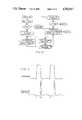
- FIG. 4is a graphical illustration of pressure and flow waveforms in the system of FIGS. 1 and 2;
- FIG. 5is an illustration generally in block diagrammatic form of an electromechanical subsystem for the ventricular assist system in accordance with FIGS. 1 and 2.
- FIG. 1there is illustrated a preferred embodiment of the ventricular system of this invention configured for pump diastole, that is that portion of the cycle when the blood inflow is filling the bladder of the active portion of the pump prior to the systolic ejection of blood from the pump.
- the deviceconsists of two major subsystems: a drive console 38 and a single-use disposable blood pump.
- the blood pumplike the natural heart, is comprised of two chambers 14 and 24 each including a flexible bladder, 16 and 26 respectively, and two valves 22 and 30. All are made from polyurethane.
- the upper chamber 14acts as a filling chamber or atrium, while the lower chamber 24 acts as a pumping chamber or ventricle.
- the pumping bladder 26is isolated from the bladder 16 of the inflow chamber 14 and systemic pressures by one polyurethane trileaflet valve 22 at its entrance and a second trileaflet valve 30 at its exit.
- the inflow chamber 14is connected via tubing and cannula to the natural atrium of the patient's heart. Filling of the pump is continuous and passive as a reuslt of atrial pressure and gravity. This is accomplished by lowering the device below the patient's atrial level, typically by less than 20 cm.
- the outflow chamber 24is emptied by air pulses delivered from the drive console 38, and is filled from the inflow chamber blood volume as the air is vented through the console. As shown in FIG.
- the input port 12conveys blood from the patient into the inflow bladder 16 situated within a generally rigid walled first chamber 14.
- This chamberis vented through opening 18 to the atmosphere allowing, in this portion of the cycle, air to flow into the chamber while the bladder 16 is in a generally collapsed condition.
- the bladder 16is not completely collapsed but remains open to allow blood from the blood inflow port 12 to pass through it and through the open trileaflet valve 22 contained in trileaflet valve housing 20.
- the blood inflowis chiefly provided by gravity.
- the outlet valve 30remains closed since its bias is such that the force of the gravity and the atrial pressure is insufficient to open it.
- the outlet valve 30is fluidically coupled to an output port 32 which in turn is connected to the arterial system of the patient.
- the drive console 38includes an air pump 50 which generates pressurized air coupled through a pressure regulator 52 to an electromagnetically controlled drive valve 46.
- the air pumpwill typically produce about 20-60 psi pressure, and the pressure regulator 52 is arranged to produce a pressure of approximately 250 mm Hg when operated as a left ventricle and about 200 mm Hg when operated as a right ventricle.
- the output of the controlled valve 46is connected through flow sensor 40 to the pneumatic tube 36. In the position shown for diastole, however, the valve 46 does not couple the air pressure to the pneumatic tube 36, but rather blocks off the pressure from the air pump 50 and opens the pneumatic tube 36 to the atmosphere, thereby venting through tube 36 the exterior portion of chamber 24.
- Flow sensor 40may be any suitable volumetric flow sensor, for example, a constricted orifice with a differential pressure measuring device.
- the output from the flow sensor 40is connected to a computer 44 which contains software for controlling the operation of the entire support system.
- This computerprovides a control signal back to electromagnetic valve 46 controlling when that valve is in the open position (as shown) or in the closed position as illustrated in FIG. 2.
- the airis driven from the exterior portion of the chamber 24 as blood fills the bladder 26 and this flow of air provides a signal from the sensor 40 to the computer 44 indicative of the flow of blood through the blood inflow into the bladder 26.
- FIG. 2the same elements are shown in the configuration for pump systole.
- the valve 46is closed, coupling pressurized air from the pump 50 through the regulator 52 and the tubing 36 to the outer portion of the chamber 24 compressing the outflow bladder 26 thereby forcing the blood which accumulated during the diastolic portion of the cycle out through the valve 30 to the arterial system of the patient.
- the valve 22closes so that blood can be ejected only through the outflow to the patient and not return into the first chamber bladder 16.
- blood inflowmay still be passing into the inflow bladder 16 and accumulating there in preparation for the next cycle.
- All of the blood contacting surfaces of the mechanical pump, that is the input and output ports, as well as the interior surfaces of the valves and bladdersare formed of a polyurethane marketed under the name Angioflex by ABIOMED, Inc. of Danvers, Mass. While this is a preferred material, any material which provides a sufficiently anti-thrombolytic surface is suitable.
- the volumes of bladders 16 and 26are each 100 cubic centimeters producing an output stroke volume of approximately 80 cubic centimeters. Typical values for the patient connections are 1/2 inch I.D. tubing.
- the system softwareoperates as basically two loops, one a "background” loop the other a "foreground” loop.
- the basic structure of this softwareis illustrated in FIG. 3.
- the background loophandles calculation of flow, calculation of systolic duration, alarm detection and display updating. Each cycle through the loop performs calculations, then checks alarm and keyboard monitor status. Flow is optimized by systolic interval adjustments made as a result of background calculations comparing actual to target stroke volume.
- the main foreground loopis initiated by a free-running 4 ms interrupt, but is only performed on alternate interrupts for an 8 ms cycle interval. During each interrupt routine, analog values are sampled and the front panel keyboard is checked for key presses. The program then switches to the control and pumping routines, testing the flow and pressure values and operating the pneumatic valves as required.
- Automatic zeroingis performed by each pumping routine every 131 seconds, slightly extending diastole and performing software recalibration of the flow transducers.
- Opening and closing of the pneumatic valves by the main foreground loopis performed as follows.
- a counteris set to the desired systolic duration, and the pneumatic valve is opened. Each 8 ms thereafter, a counter is decremented by 8 ms and tested until it becomes zero or negative, and the pneumatic valve is closed.
- Diastolebegins by monitoring the flow value for the major drop off to occur, then waiting a blanking period, then sampling the flow value. When repeated testing shows this flow has dropped to a small specified value, diastole is considered finished, the valve is opened, and the cycle repeats.
- the softwarecontrols the duration of the diastolic mode by terminating this mode when the flow rate which is measured at sensor 40 decreases below a specific level indicative of substantial filling of the bladder 26.
- the computerprovides a signal to the electromagnetic valve 46 changing its position from the open position in which it is venting the air from tube 36 to atmosphere to a closed position in which it receives pressurized air from the pump 50 through the pressure regulator 52. This closing of the valve initiates the systolic portion of the cycle.
- the softwarecontrols the duration of systole by establishing the duration as an initial predetermined time period, for example, 800 milliseconds, which is intended to be sufficient to empty eighty percent of the bladder 26, but to stop well short of complete collapse of the bladder walls which could damage the blood cells.
- the nominal initial predetermined value selectedis set to be larger than the target stroke volume so that each total beat or stroke of the pump systole time may be decremented down by a suitable value, for example, 25 milliseconds until the duration of the systolic pulse is sufficient to expel a volume of blood substantially equal to the target stroke volume.
- the determination of the amount of blood being ejectedis made by integrating the signal from the flow sensor 40 for the previous diastolic portion of the cycle and taking the average value for the previous four beats for each beat. This average value is compared in computer 44 to the target value for stroke volume. The result of this comparison is used to determine whether the systole time should continue to be decremented. When the comparison in the computer 44 shows that the decremented period has reached a value where the actual output blood flow volume per beat equals the target value, the time duration for the systolic interval is no longer decremented.
- the time durationis incremented by a specific amount and the stroke volume compared to the target value. If the comparison shows the previous duration was correct, the duration is immediately reduced back to that value. If the new value is below target value, then the duration is again incremented two minutes later.
- the time duration of the systolic pulseis not incremented on every beat, but rather, by periodically being interrupted and incremented, a system is established which does not oscillate about a particular value.
- Transients in pressure and floware created and reflected in the sensed flow signals at the time of change of the electromagnetic valve position from opened to closed and closed to open.
- the computeris therefore programmed to ignore these transients and operate only on the values which take place thereafter.
- Controlled valve 46commences the pumping action and, as discussed above, systole ends after an adjustable time duration which is optimized in the background loop of the software to produce about the eighty to ninety percent collapse of the pumping bladder 26. This portion of the cycle also includes specific software to detect and prevent total collapse of the pumping bladder.
- the electromagnetic valve 46changes to the opposite position which allows air in the exterior volume of the chamber 24 to escape through the flow sensor to the atmosphere and, as discussed above, the diastole ends when this air flow has decreased to a very small value or, alternatively when a maximum time has elapsed.
- FIG. 4typical time waveforms are shown for the pressure and expanded negative flow signals. Negative flow is defined as flow in the direction away from the chamber 24, while positive flow is defined as flow in the direction toward the chamber 24.
- point Ais the time at which the electromagnetic valve 46 opens, allowing the gas to pass through the tubing 36 to the chamber 24. Thus the gas pressure increases at this point and remains elevated until termination of the systolic period when the valve 46 closes at time B.
- the negative flowthen commences approximately at point B giving rise to a transient in the sensed negative flow which appears between times B and C.
- the diastolic periodthen follows until the decrease of the negative flow below a preset value which occurs at A', terminating the diastolic period.
- the programincludes a background loop which provides for computation and display of flow and also for the control over the adjustment of the systolic duration.
- a background loopwhich provides for computation and display of flow and also for the control over the adjustment of the systolic duration.
- the differential pressure transducer 40In order to determine flow, data is obtained during the diastolic portion of the beat.
- the differential pressure transducer 40generates a signal whose polarity and amplitude represent the flow through the sensor.
- the values of the sensorare sampled every eight milliseconds. Since the differential pressure signal from the sensor 40 is assumed to be proportional to the square of the air flow velocity, the integral of this value (which determines the volumetric flow velocity per beat) is computed as a value which is proportional to the square root of each data point.
- the actual flow integral measured in foregroundis adjusted to remove the exponential artifact due to the transient at depressurization which is done by computing the area under an exponential curve fitted to the initial portion of the artifact.
- the adjusted value of the integralis accumulated for four beats. After the fourth beat, the accumulated sum of the integrals is converted to a flow reading which is used to compute the running average flow value. This average is calculated by adding each new four beat sum to the previously calculated value then dividing the total by two. It is this average of flow value which is used as the basis for systolic period duration as well as for alarms to indicate that the flow has fallen below a predetermined lower minimum level.
- the pumping program described aboveis for normal operation.
- the systemcan also be manually converted to a weaning mode in which the total flow volume produced over a period of time by the pump is set to any selected one of a group of values less than would result by allowing the pump to operate in the normal mode.
- This weaning modeis used to gradually shift the pumping load of the blood onto the patient's own heart. This is achieved by varying the beat rate by arbitrarily extending the length of diastole until the total length of the beat is a value sufficient to have the average flow output volume from the support system equal to the selected amount for the weaning procedure. If, during the weaning mode, the blood volume is below this value, the system automatically increases the beat rate until the duration of each beat is sufficient to produce the target value of the stroke volume, exactly as it occurs in the non-weaning mode.
- FIG. 5is an illustration of the electromechanical elements of the cardiac system of this invention.
- the air compressor 50which has a filter 60 at its intake to filter the input air, provides output pressure to regulator 52.
- a relief valve 61is a safety relief in the event that the pressure from the compressor exceeds 65 psi.
- Plenum 62provides a reservoir for ensuring that a relatively high flow rate of the output gas from the pressure regulator 52 is supplied to the input of the two position solenoid valve 46 which is controlled from computer 44.
- the solenoid valveis open in closed position and therefore does not pass the pressurized air from regulator 52 to the pump connector 36.
- the systemis in the second position of the solenoid valve in which air from the pump connector 36 passes through the orifice block 64 to transfer valve 70 and thence through filter 74 to the outside atmosphere.
- the flow of air in this negative directionis measured by virtue of the differential pressure transducer 40 measuring the pressure drop across the orifice block, which is indicative of the flow velocity.
- the gauge pressure transducer 66provides an output indicating to the computer 44 changes in pressure in chamber 24.
- the transfer valve 70is included to provide for emergency operation of the entire cardiac system by means of a foot pump 72.
- the transfer valve 70is actuated to connect the gas line 36 directly to foot pump 72, which can be manually operated in an emergency to continue supplying the pressure necessary to operate the cardiac assist system.
Landscapes
- Health & Medical Sciences (AREA)
- Engineering & Computer Science (AREA)
- Heart & Thoracic Surgery (AREA)
- Cardiology (AREA)
- Biomedical Technology (AREA)
- Anesthesiology (AREA)
- Mechanical Engineering (AREA)
- Hematology (AREA)
- Life Sciences & Earth Sciences (AREA)
- Animal Behavior & Ethology (AREA)
- General Health & Medical Sciences (AREA)
- Public Health (AREA)
- Veterinary Medicine (AREA)
- External Artificial Organs (AREA)
Abstract
Description
Claims (8)
Priority Applications (2)
| Application Number | Priority Date | Filing Date | Title |
|---|---|---|---|
| US07/055,648US4782817A (en) | 1987-05-29 | 1987-05-29 | Ventricular support system |
| JP63128556AJPS6452472A (en) | 1987-05-29 | 1988-05-27 | Cardiac ventricle support system |
Applications Claiming Priority (1)
| Application Number | Priority Date | Filing Date | Title |
|---|---|---|---|
| US07/055,648US4782817A (en) | 1987-05-29 | 1987-05-29 | Ventricular support system |
Publications (1)
| Publication Number | Publication Date |
|---|---|
| US4782817Atrue US4782817A (en) | 1988-11-08 |
Family
ID=21999257
Family Applications (1)
| Application Number | Title | Priority Date | Filing Date |
|---|---|---|---|
| US07/055,648Expired - LifetimeUS4782817A (en) | 1987-05-29 | 1987-05-29 | Ventricular support system |
Country Status (2)
| Country | Link |
|---|---|
| US (1) | US4782817A (en) |
| JP (1) | JPS6452472A (en) |
Cited By (40)
| Publication number | Priority date | Publication date | Assignee | Title |
|---|---|---|---|---|
| US5006111A (en)* | 1985-04-05 | 1991-04-09 | Kureha Kagaku Kogyo Kabushiki Kaisha | Medical pump device and a method for compensating a deviation of a measured blood flow rate |
| US5344385A (en)* | 1991-09-30 | 1994-09-06 | Thoratec Laboratories Corporation | Step-down skeletal muscle energy conversion system |
| WO1994027657A1 (en)* | 1993-05-28 | 1994-12-08 | Mohrman David E | Artificial heart pump |
| US5380267A (en)* | 1993-06-18 | 1995-01-10 | Datascope Investment Corp. | Noise-attenuating pneumatic compressor and medical apparatus incorporating same |
| US5445613A (en)* | 1993-07-16 | 1995-08-29 | Rocky Mountain Research, Inc. | Condition detection system and clamp |
| US5487649A (en)* | 1993-09-29 | 1996-01-30 | American Hydro-Surgical Instruments, Inc. | Infinitely variable pneumatic pulsatile pump |
| US5833619A (en)* | 1997-05-15 | 1998-11-10 | L. Vad Technology, Inc. | External blood pressure sensor apparatus and method |
| US6042532A (en)* | 1998-03-09 | 2000-03-28 | L. Vad Technology, Inc. | Pressure control system for cardiac assist device |
| US6132363A (en)* | 1997-09-30 | 2000-10-17 | L.Vad Technology, Inc. | Cardiovascular support control system |
| EP1070511A4 (en)* | 1998-04-06 | 2001-01-24 | Fujio Miyawaki | Auxiliary mechanical heart promoting the restoration of heart function |
| US6293901B1 (en)* | 1997-11-26 | 2001-09-25 | Vascor, Inc. | Magnetically suspended fluid pump and control system |
| US6375607B1 (en)* | 1997-11-26 | 2002-04-23 | Vascor, Inc. | Magnetically suspended fluid pump and control system |
| US6397689B1 (en) | 1999-03-10 | 2002-06-04 | Ysi Incorporated | Sample probe |
| US6511412B1 (en) | 1998-09-30 | 2003-01-28 | L. Vad Technology, Inc. | Cardivascular support control system |
| WO2002088547A3 (en)* | 2001-04-30 | 2003-03-13 | Berlin Heart Ag | Method for controlling an assist pump for fluid delivery systems with pulsatile pressure |
| US6735532B2 (en) | 1998-09-30 | 2004-05-11 | L. Vad Technology, Inc. | Cardiovascular support control system |
| US20050131271A1 (en)* | 2002-01-07 | 2005-06-16 | Micromed Technology Inc. | Method and system for physiologic control of an implantable blood pump |
| EP1674119A1 (en)* | 2004-12-22 | 2006-06-28 | Tecnobiomedica S.p.A. | A pulsator device, method of operating the same, corresponding system and computer program |
| US20070021646A1 (en)* | 2005-07-22 | 2007-01-25 | Giancarlo Nardi | Device for cardiocirculatory assistance |
| US7468050B1 (en) | 2002-12-27 | 2008-12-23 | L. Vad Technology, Inc. | Long term ambulatory intra-aortic balloon pump |
| US20090270981A1 (en)* | 2008-04-23 | 2009-10-29 | Syncardia Systems, Inc. | Apparatus and method for pneumatically driving an implantable medical device |
| WO2013087960A1 (en)* | 2011-12-16 | 2013-06-20 | Salvador Merce Vives | Device for generating a synchronizable physiological pulsatile flow for cardiac surgery and extracorporeal cardiac assist |
| EP2712636A1 (en)* | 2012-09-26 | 2014-04-02 | Fundacja Rozwoju Kardiochirurgii Im. Prof. Zbigniewa Religi | A pediatric heart assist pump |
| GB2553801A (en)* | 2016-09-14 | 2018-03-21 | Haemaflow Ltd | Blood pump |
| US10722631B2 (en) | 2018-02-01 | 2020-07-28 | Shifamed Holdings, Llc | Intravascular blood pumps and methods of use and manufacture |
| US20210275794A1 (en)* | 2018-07-31 | 2021-09-09 | Abiomed, Inc. | Systems and methods for controlling a heart pump to minimize myocardial oxygen consumption |
| US11185677B2 (en) | 2017-06-07 | 2021-11-30 | Shifamed Holdings, Llc | Intravascular fluid movement devices, systems, and methods of use |
| US11511103B2 (en) | 2017-11-13 | 2022-11-29 | Shifamed Holdings, Llc | Intravascular fluid movement devices, systems, and methods of use |
| CN115779258A (en)* | 2022-12-14 | 2023-03-14 | 安徽通灵仿生科技有限公司 | A balloon adjustment method and device for IABP |
| US11654275B2 (en) | 2019-07-22 | 2023-05-23 | Shifamed Holdings, Llc | Intravascular blood pumps with struts and methods of use and manufacture |
| US11724089B2 (en) | 2019-09-25 | 2023-08-15 | Shifamed Holdings, Llc | Intravascular blood pump systems and methods of use and control thereof |
| US11793417B2 (en)* | 2015-05-20 | 2023-10-24 | Thd S.P.A. | Apparatus and a method of measurement thereof |
| US11964145B2 (en) | 2019-07-12 | 2024-04-23 | Shifamed Holdings, Llc | Intravascular blood pumps and methods of manufacture and use |
| US12102815B2 (en) | 2019-09-25 | 2024-10-01 | Shifamed Holdings, Llc | Catheter blood pumps and collapsible pump housings |
| US12121713B2 (en) | 2019-09-25 | 2024-10-22 | Shifamed Holdings, Llc | Catheter blood pumps and collapsible blood conduits |
| US12161857B2 (en) | 2018-07-31 | 2024-12-10 | Shifamed Holdings, Llc | Intravascular blood pumps and methods of use |
| EP4464325A3 (en)* | 2011-05-24 | 2025-01-29 | DEKA Products Limited Partnership | Blood treatment systems and methods |
| US12220570B2 (en) | 2018-10-05 | 2025-02-11 | Shifamed Holdings, Llc | Intravascular blood pumps and methods of use |
| US12409310B2 (en) | 2019-12-11 | 2025-09-09 | Shifamed Holdings, Llc | Descending aorta and vena cava blood pumps |
| US12421952B2 (en) | 2013-03-15 | 2025-09-23 | Deka Products Limited Partnership | Reciprocating diaphragm pumps for blood treatment systems and methods |
Families Citing this family (2)
| Publication number | Priority date | Publication date | Assignee | Title |
|---|---|---|---|---|
| JPH089775B2 (en)* | 1990-11-27 | 1996-01-31 | 日本鋼管株式会社 | Ion plating method and apparatus |
| ES2284396B1 (en)* | 2006-04-20 | 2008-10-16 | Salvador Merce Vives | PUMP FOR BLOOD PERFUSION. |
Citations (15)
| Publication number | Priority date | Publication date | Assignee | Title |
|---|---|---|---|---|
| US3376660A (en)* | 1965-07-12 | 1968-04-09 | Westinghouse Electric Corp | Circulatory system simulator |
| US3639084A (en)* | 1970-04-06 | 1972-02-01 | Baxter Laboratories Inc | Mechanism for control pulsatile fluid flow |
| US3718044A (en)* | 1971-12-07 | 1973-02-27 | Us Army | Flow meter for indirectly measuring the flow of blood from a blood pump |
| DE2501552A1 (en)* | 1974-01-21 | 1975-07-24 | Baxter Laboratories Inc | DEVICE FOR Bypassing the blood circulation in the heart and lungs |
| US3955557A (en)* | 1973-10-01 | 1976-05-11 | Hiroyuki Takagi | Blood pump for use in an artificial heart or such purpose |
| DE2658104A1 (en)* | 1976-05-19 | 1977-12-01 | Herwig Dipl Ing Dr Thoma | Automatic operation of blood circulating pump - with hydraulic or pneumatic diaphragm pump and diaphragm position detector |
| US4080958A (en)* | 1976-02-27 | 1978-03-28 | Datascope Corporation | Apparatus for aiding and improving the blood flow in patients |
| GB2004942A (en)* | 1977-09-21 | 1979-04-11 | Bosio R | Pump for producing an artificial blood circulation |
| SU733688A1 (en)* | 1977-11-23 | 1980-05-15 | Институт Трансплантации Органов И Тканей | Apparatus for indirect monitoring of efficiency of heart prosthesis with external pneumatic drive |
| SU844815A1 (en)* | 1978-12-11 | 1981-07-07 | за вители | Diaphragm pump |
| US4353220A (en)* | 1980-06-17 | 1982-10-12 | Mechanical Technology Incorporated | Resonant piston compressor having improved stroke control for load-following electric heat pumps and the like |
| US4465063A (en)* | 1982-05-25 | 1984-08-14 | University Of Utah | Cardiac flow measurement system and method |
| US4583525A (en)* | 1982-03-30 | 1986-04-22 | Aisin Seiki K.K. | Artificial heart driving apparatus |
| US4611578A (en)* | 1983-05-03 | 1986-09-16 | Forschungsgesellschaft fur Biomedizinischs Technik E.V. Goethestrasse | Redundant piston pump for the operation of single or multiple chambered pneumatic blood pumps |
| US4662355A (en)* | 1983-08-08 | 1987-05-05 | Alain Pieronne | Pump regulation device |
- 1987
- 1987-05-29USUS07/055,648patent/US4782817A/ennot_activeExpired - Lifetime
- 1988
- 1988-05-27JPJP63128556Apatent/JPS6452472A/enactiveGranted
Patent Citations (16)
| Publication number | Priority date | Publication date | Assignee | Title |
|---|---|---|---|---|
| US3376660A (en)* | 1965-07-12 | 1968-04-09 | Westinghouse Electric Corp | Circulatory system simulator |
| US3639084A (en)* | 1970-04-06 | 1972-02-01 | Baxter Laboratories Inc | Mechanism for control pulsatile fluid flow |
| US3718044A (en)* | 1971-12-07 | 1973-02-27 | Us Army | Flow meter for indirectly measuring the flow of blood from a blood pump |
| US3955557A (en)* | 1973-10-01 | 1976-05-11 | Hiroyuki Takagi | Blood pump for use in an artificial heart or such purpose |
| DE2501552A1 (en)* | 1974-01-21 | 1975-07-24 | Baxter Laboratories Inc | DEVICE FOR Bypassing the blood circulation in the heart and lungs |
| US4080958A (en)* | 1976-02-27 | 1978-03-28 | Datascope Corporation | Apparatus for aiding and improving the blood flow in patients |
| DE2658104A1 (en)* | 1976-05-19 | 1977-12-01 | Herwig Dipl Ing Dr Thoma | Automatic operation of blood circulating pump - with hydraulic or pneumatic diaphragm pump and diaphragm position detector |
| US4212589A (en)* | 1977-09-21 | 1980-07-15 | Roberto Bosio | Device for producing an artificial blood circulation |
| GB2004942A (en)* | 1977-09-21 | 1979-04-11 | Bosio R | Pump for producing an artificial blood circulation |
| SU733688A1 (en)* | 1977-11-23 | 1980-05-15 | Институт Трансплантации Органов И Тканей | Apparatus for indirect monitoring of efficiency of heart prosthesis with external pneumatic drive |
| SU844815A1 (en)* | 1978-12-11 | 1981-07-07 | за вители | Diaphragm pump |
| US4353220A (en)* | 1980-06-17 | 1982-10-12 | Mechanical Technology Incorporated | Resonant piston compressor having improved stroke control for load-following electric heat pumps and the like |
| US4583525A (en)* | 1982-03-30 | 1986-04-22 | Aisin Seiki K.K. | Artificial heart driving apparatus |
| US4465063A (en)* | 1982-05-25 | 1984-08-14 | University Of Utah | Cardiac flow measurement system and method |
| US4611578A (en)* | 1983-05-03 | 1986-09-16 | Forschungsgesellschaft fur Biomedizinischs Technik E.V. Goethestrasse | Redundant piston pump for the operation of single or multiple chambered pneumatic blood pumps |
| US4662355A (en)* | 1983-08-08 | 1987-05-05 | Alain Pieronne | Pump regulation device |
Cited By (56)
| Publication number | Priority date | Publication date | Assignee | Title |
|---|---|---|---|---|
| US5006111A (en)* | 1985-04-05 | 1991-04-09 | Kureha Kagaku Kogyo Kabushiki Kaisha | Medical pump device and a method for compensating a deviation of a measured blood flow rate |
| US5344385A (en)* | 1991-09-30 | 1994-09-06 | Thoratec Laboratories Corporation | Step-down skeletal muscle energy conversion system |
| US5653676A (en)* | 1991-09-30 | 1997-08-05 | Thoratec Laboratories Corporation | Step-down skeletal muscle energy conversion method |
| US5701919A (en)* | 1991-09-30 | 1997-12-30 | Thoratec Laboratories Corporation | Step-down skeletal muscle energy conversion system |
| US5984857A (en)* | 1991-09-30 | 1999-11-16 | Thoratec Laboratories Corporation | Step-down skeletal muscle energy conversion system |
| WO1994027657A1 (en)* | 1993-05-28 | 1994-12-08 | Mohrman David E | Artificial heart pump |
| US5380267A (en)* | 1993-06-18 | 1995-01-10 | Datascope Investment Corp. | Noise-attenuating pneumatic compressor and medical apparatus incorporating same |
| US5445613A (en)* | 1993-07-16 | 1995-08-29 | Rocky Mountain Research, Inc. | Condition detection system and clamp |
| US5487649A (en)* | 1993-09-29 | 1996-01-30 | American Hydro-Surgical Instruments, Inc. | Infinitely variable pneumatic pulsatile pump |
| US5833619A (en)* | 1997-05-15 | 1998-11-10 | L. Vad Technology, Inc. | External blood pressure sensor apparatus and method |
| US6132363A (en)* | 1997-09-30 | 2000-10-17 | L.Vad Technology, Inc. | Cardiovascular support control system |
| US6375607B1 (en)* | 1997-11-26 | 2002-04-23 | Vascor, Inc. | Magnetically suspended fluid pump and control system |
| US6293901B1 (en)* | 1997-11-26 | 2001-09-25 | Vascor, Inc. | Magnetically suspended fluid pump and control system |
| US6042532A (en)* | 1998-03-09 | 2000-03-28 | L. Vad Technology, Inc. | Pressure control system for cardiac assist device |
| US6443884B1 (en) | 1998-04-06 | 2002-09-03 | Fujio Miyawaki | Ventricular assist device capable of promoting recovery of cardiac function |
| EP1070511A4 (en)* | 1998-04-06 | 2001-01-24 | Fujio Miyawaki | Auxiliary mechanical heart promoting the restoration of heart function |
| US6735532B2 (en) | 1998-09-30 | 2004-05-11 | L. Vad Technology, Inc. | Cardiovascular support control system |
| US6511412B1 (en) | 1998-09-30 | 2003-01-28 | L. Vad Technology, Inc. | Cardivascular support control system |
| US6397689B1 (en) | 1999-03-10 | 2002-06-04 | Ysi Incorporated | Sample probe |
| US20050019167A1 (en)* | 2001-04-30 | 2005-01-27 | Peter Nusser | Method and controlling an assist pump for fluid delivery systems with pulsatile pressure |
| WO2002088547A3 (en)* | 2001-04-30 | 2003-03-13 | Berlin Heart Ag | Method for controlling an assist pump for fluid delivery systems with pulsatile pressure |
| RU2277937C2 (en)* | 2001-04-30 | 2006-06-20 | Берлин Харт Аг | Method for controlling auxiliary pump operation for liquid transfer systems under pulsing pressure conditions |
| US7150711B2 (en) | 2001-04-30 | 2006-12-19 | Berlin Heart Ag | Method for controlling an assist pump for fluid delivery systems with pulsatile pressure |
| US20050131271A1 (en)* | 2002-01-07 | 2005-06-16 | Micromed Technology Inc. | Method and system for physiologic control of an implantable blood pump |
| US8323173B2 (en)* | 2002-01-07 | 2012-12-04 | Micromed Technology, Inc. | Method and system for physiologic control of an implantable blood pump |
| US7468050B1 (en) | 2002-12-27 | 2008-12-23 | L. Vad Technology, Inc. | Long term ambulatory intra-aortic balloon pump |
| EP1674119A1 (en)* | 2004-12-22 | 2006-06-28 | Tecnobiomedica S.p.A. | A pulsator device, method of operating the same, corresponding system and computer program |
| US20060236756A1 (en)* | 2004-12-22 | 2006-10-26 | Tecnobiomedica S.P.A. | Pulsator device, method of operating same, corresponding system and computer program product |
| US7367959B2 (en)* | 2005-07-22 | 2008-05-06 | A.N.B. Technology S.R.L. | Device for cardiocirculatory assistance |
| US20070021646A1 (en)* | 2005-07-22 | 2007-01-25 | Giancarlo Nardi | Device for cardiocirculatory assistance |
| US7811318B2 (en) | 2008-04-23 | 2010-10-12 | Syncardia Systems, Inc. | Apparatus and method for pneumatically driving an implantable medical device |
| US20090270981A1 (en)* | 2008-04-23 | 2009-10-29 | Syncardia Systems, Inc. | Apparatus and method for pneumatically driving an implantable medical device |
| EP4464325A3 (en)* | 2011-05-24 | 2025-01-29 | DEKA Products Limited Partnership | Blood treatment systems and methods |
| WO2013087960A1 (en)* | 2011-12-16 | 2013-06-20 | Salvador Merce Vives | Device for generating a synchronizable physiological pulsatile flow for cardiac surgery and extracorporeal cardiac assist |
| EP2712636A1 (en)* | 2012-09-26 | 2014-04-02 | Fundacja Rozwoju Kardiochirurgii Im. Prof. Zbigniewa Religi | A pediatric heart assist pump |
| US12421952B2 (en) | 2013-03-15 | 2025-09-23 | Deka Products Limited Partnership | Reciprocating diaphragm pumps for blood treatment systems and methods |
| US11793417B2 (en)* | 2015-05-20 | 2023-10-24 | Thd S.P.A. | Apparatus and a method of measurement thereof |
| GB2553801A (en)* | 2016-09-14 | 2018-03-21 | Haemaflow Ltd | Blood pump |
| US11957820B2 (en) | 2016-09-14 | 2024-04-16 | Haemaflow Limited | Blood pump |
| US11185677B2 (en) | 2017-06-07 | 2021-11-30 | Shifamed Holdings, Llc | Intravascular fluid movement devices, systems, and methods of use |
| US11717670B2 (en) | 2017-06-07 | 2023-08-08 | Shifamed Holdings, LLP | Intravascular fluid movement devices, systems, and methods of use |
| US11511103B2 (en) | 2017-11-13 | 2022-11-29 | Shifamed Holdings, Llc | Intravascular fluid movement devices, systems, and methods of use |
| US12076545B2 (en) | 2018-02-01 | 2024-09-03 | Shifamed Holdings, Llc | Intravascular blood pumps and methods of use and manufacture |
| US10722631B2 (en) | 2018-02-01 | 2020-07-28 | Shifamed Holdings, Llc | Intravascular blood pumps and methods of use and manufacture |
| US11229784B2 (en) | 2018-02-01 | 2022-01-25 | Shifamed Holdings, Llc | Intravascular blood pumps and methods of use and manufacture |
| US12161857B2 (en) | 2018-07-31 | 2024-12-10 | Shifamed Holdings, Llc | Intravascular blood pumps and methods of use |
| US12329956B2 (en)* | 2018-07-31 | 2025-06-17 | Abiomed, Inc. | Systems and methods for controlling a heart pump to minimize myocardial oxygen consumption |
| US20210275794A1 (en)* | 2018-07-31 | 2021-09-09 | Abiomed, Inc. | Systems and methods for controlling a heart pump to minimize myocardial oxygen consumption |
| US12220570B2 (en) | 2018-10-05 | 2025-02-11 | Shifamed Holdings, Llc | Intravascular blood pumps and methods of use |
| US11964145B2 (en) | 2019-07-12 | 2024-04-23 | Shifamed Holdings, Llc | Intravascular blood pumps and methods of manufacture and use |
| US11654275B2 (en) | 2019-07-22 | 2023-05-23 | Shifamed Holdings, Llc | Intravascular blood pumps with struts and methods of use and manufacture |
| US12121713B2 (en) | 2019-09-25 | 2024-10-22 | Shifamed Holdings, Llc | Catheter blood pumps and collapsible blood conduits |
| US12102815B2 (en) | 2019-09-25 | 2024-10-01 | Shifamed Holdings, Llc | Catheter blood pumps and collapsible pump housings |
| US11724089B2 (en) | 2019-09-25 | 2023-08-15 | Shifamed Holdings, Llc | Intravascular blood pump systems and methods of use and control thereof |
| US12409310B2 (en) | 2019-12-11 | 2025-09-09 | Shifamed Holdings, Llc | Descending aorta and vena cava blood pumps |
| CN115779258A (en)* | 2022-12-14 | 2023-03-14 | 安徽通灵仿生科技有限公司 | A balloon adjustment method and device for IABP |
Also Published As
| Publication number | Publication date |
|---|---|
| JPS6452472A (en) | 1989-02-28 |
| JPH0450831B2 (en) | 1992-08-17 |
Similar Documents
| Publication | Publication Date | Title |
|---|---|---|
| US4782817A (en) | Ventricular support system | |
| US5098370A (en) | Heart assist device | |
| AU740206B2 (en) | Pressure control system for cardiac assist device | |
| EP1058512B1 (en) | External blood pressure sensor apparatus | |
| EP2988795B1 (en) | Biomedical apparatus for pumping blood of a human or an animal patient through a secondary intra- or extracorporeal blood circuit | |
| US4796606A (en) | Drive unit for medical pump | |
| EP0603186B1 (en) | A cup for ventricular cardiac massage, and apparatus incorporating the same | |
| EP0075606B1 (en) | System for extracorporeal circulation of blood | |
| US5413110A (en) | Computer gated positive expiratory pressure method | |
| EP0096495B1 (en) | Cardiac flow measurement system and method | |
| US3911897A (en) | Heart assist device | |
| US5743845A (en) | Biventricular pulsatile cardiac support system having a mechanically balanced stroke volume | |
| EP1889634A1 (en) | A ventricular assist device and related computer program product | |
| WO1987006040A1 (en) | Computer gated positive expiratory pressure system | |
| US12409314B2 (en) | Pump system, control unit and method for operating a pump system | |
| JPH064092B2 (en) | Blood pump | |
| Min et al. | Automatic control algorithm for cardiac output regulation of the total artificial heart (TAH) | |
| CN119215323A (en) | An adaptive driving method for a total artificial heart | |
| Choi et al. | Development of a stroke output control algorithm using a fuzzy logic for a left ventricular assist device | |
| Arai et al. | Optimal control algorithm for pneumatic ventricular assist devices: Its application to automatic control and monitoring of ventricular assist devices | |
| SU952263A1 (en) | Blood pump | |
| JPH05164054A (en) | Fluid feed pumping device | |
| EP0852940A2 (en) | Heart massage apparatus | |
| Leitz et al. | Testing Of Artificial Hearts In A Circulation Model | |
| Woodward | Captain Daniel E. Nunn (MC.)(2) |
Legal Events
| Date | Code | Title | Description |
|---|---|---|---|
| AS | Assignment | Owner name:ABIOMED CARDIOVASCULAR, INC., 33 CHERRY HILL DR., Free format text:ASSIGNMENT OF ASSIGNORS INTEREST.;ASSIGNORS:SINGH, PARAM I.;BOLT, WILLIAM J.;SAWYER, DANA C.;REEL/FRAME:004716/0954 Effective date:19870528 | |
| STCF | Information on status: patent grant | Free format text:PATENTED CASE | |
| AS | Assignment | Owner name:ABIOMED LIMITED PARTNERSHIP, 33 CHERRY HILL DRIVE, Free format text:ASSIGNMENT OF ASSIGNORS INTEREST.;ASSIGNOR:ABIOMED CARDIOVASCULAR, INC.;REEL/FRAME:005146/0195 Effective date:19890518 | |
| AS | Assignment | Owner name:ABIOMED, INC., 33 CHERRY HILL DRIVE, DANVERS, MA A Free format text:ASSIGNMENT OF ASSIGNORS INTEREST.;ASSIGNOR:ABIOMED RESEARCH & DEVELOPMENT, INC.;REEL/FRAME:005557/0816 Effective date:19901212 | |
| FEPP | Fee payment procedure | Free format text:PAYOR NUMBER ASSIGNED (ORIGINAL EVENT CODE: ASPN); ENTITY STATUS OF PATENT OWNER: SMALL ENTITY | |
| FPAY | Fee payment | Year of fee payment:4 | |
| AS | Assignment | Owner name:ABIOMED, INC. A DE CORP. Free format text:TO CORRECT THE STATE OF INCORPORATION OF ASSIGNEE IN ASSIGNMENT PREVIOUSLY RECORDED AT REEL 5589 FRAME 770 ASSIGNOR HEREBY CONFIRMS THE ENTIRE INTEREST IN SAID PATENTS TO ASSIGNEE.;ASSIGNOR:ABIOMED LIMITED PARTNERSHIP BY ABIOMED RESEARCH & DEVELOPMENT, INC., GENERAL PARTNER;REEL/FRAME:006306/0285 Effective date:19911018 | |
| AS | Assignment | Owner name:ABIOMED, INC., MASSACHUSETTS Free format text:CORRECTED ASSIGNMENT TO CORRECT STATE OF INCORPORATION ON ASSIGNMENT RECORDED AT REEL 5557 FRAME 816-819;ASSIGNOR:ABIOMED LIMITED PARTNERSHIP, A MA CORPORATION;REEL/FRAME:006359/0291 Effective date:19910529 | |
| FPAY | Fee payment | Year of fee payment:8 | |
| FPAY | Fee payment | Year of fee payment:12 | |
| FEPP | Fee payment procedure | Free format text:PAYOR NUMBER ASSIGNED (ORIGINAL EVENT CODE: ASPN); ENTITY STATUS OF PATENT OWNER: SMALL ENTITY Free format text:PAYER NUMBER DE-ASSIGNED (ORIGINAL EVENT CODE: RMPN); ENTITY STATUS OF PATENT OWNER: SMALL ENTITY |