US4782550A - Automatic surface-treating apparatus - Google Patents
Automatic surface-treating apparatusDownload PDFInfo
- Publication number
- US4782550A US4782550AUS07/155,312US15531288AUS4782550AUS 4782550 AUS4782550 AUS 4782550AUS 15531288 AUS15531288 AUS 15531288AUS 4782550 AUS4782550 AUS 4782550A
- Authority
- US
- United States
- Prior art keywords
- members
- treating apparatus
- carpet
- automatic surface
- automatic
- Prior art date
- Legal status (The legal status is an assumption and is not a legal conclusion. Google has not performed a legal analysis and makes no representation as to the accuracy of the status listed.)
- Expired - Fee Related
Links
Images


Classifications
- A—HUMAN NECESSITIES
- A47—FURNITURE; DOMESTIC ARTICLES OR APPLIANCES; COFFEE MILLS; SPICE MILLS; SUCTION CLEANERS IN GENERAL
- A47L—DOMESTIC WASHING OR CLEANING; SUCTION CLEANERS IN GENERAL
- A47L11/00—Machines for cleaning floors, carpets, furniture, walls, or wall coverings
- A47L11/40—Parts or details of machines not provided for in groups A47L11/02 - A47L11/38, or not restricted to one of these groups, e.g. handles, arrangements of switches, skirts, buffers, levers
- A47L11/4061—Steering means; Means for avoiding obstacles; Details related to the place where the driver is accommodated
- A—HUMAN NECESSITIES
- A47—FURNITURE; DOMESTIC ARTICLES OR APPLIANCES; COFFEE MILLS; SPICE MILLS; SUCTION CLEANERS IN GENERAL
- A47L—DOMESTIC WASHING OR CLEANING; SUCTION CLEANERS IN GENERAL
- A47L2201/00—Robotic cleaning machines, i.e. with automatic control of the travelling movement or the cleaning operation
- A47L2201/04—Automatic control of the travelling movement; Automatic obstacle detection
Definitions
- This inventionis related generally to automatic apparatus for the treatment of horizontal surfaces and, more particularly, to surface-treating apparatus of the type supported by, traversing, and treating horizontal surfaces, primarily carpeted floors, unattended by an operator.
- a carpeted surfaceis fibrous, thick and a bit irregular when compared to a flat hard floor; the path of a wheeled device traversing carpet can be affected by these qualities.
- carpet cleaning other than simple vacuumingcan involve a number of steps complicating automation.
- Automatic surface-treating equipment of the prior arthas a number of problems and shortcomings. More specifically, improved automatic carpet-cleaning equipment is needed.
- Automatic carpet-cleaning or floor-cleaning devicestypically perform a number of functions as they pass over the carpet or other floor surface to be cleaned. Such functions may include applying a cleaning composition, scrubbing in some manner, and removing the dirt and used cleaning composition.
- Such multiple stepsmay be carried out in a single pass or more then one pass along a first path. After the first path has been treated, it is necessary to repeat the same step or steps along a second path which is parallel to the first path. It is very important that the second path be contiguous with the first path so that there are no neglected strips between the paths.
- Another object of this inventionis to provide an improved fully automatic surface-treating device which can cut labor costs in tasks such as carpet cleaning.
- Another object of this inventionis to provide an improved automatic surface-treating apparatus having accurate surface-traversing movements even though unattended by an operator.
- Another object of this inventionis to provide an improved surface-treating apparatus which can accurately side-step from one surface-treatment path to the next.
- Another object of this inventionis to provide an improved automatic surface-treating apparatus which is programmable by an operator such that it properly carries out carpet-cleaning operations or other surface-treating operations.
- This inventionis an automatic surface-treating apparatus of the type supported by and traversing a horizontal surface unattended.
- the inventionis an improvement which overcomes shortcomings of the prior art.
- the inventionis a simple device which has an inherently accurate side-stepping ability; this provides improved accuracy in its surface-traversing movements.
- the deviceis also simple in construction such that it provides ample space for surface-treating elements and assemblies, such as those necessary for carpet cleaning.
- the inventionis particularly useful as an automatic unattended carpet-cleaning apparatus.
- the automatic surface-cleaning apparatus of this inventionincludes: a frame; mobility members such as wheels or tracks on the frame which are rotatable about axes extending in a first horizontal direction; means on the frame for treating the surface as the apparatus automatically traverses the surface; and side-step members on the frame which are rotatable about horizontal axes oriented transverse to the first direction and located a given distance about the surface.
- Each side-step memberhas a first sector and a second sector, both of which are important to the manner in which the invention operates.
- This first sectorhas what is referred to herein as a far periphery which is spaced from its axis by more than the given distance, that is, by more than the distance by which the side-step axes are above the surface on which the apparatus is supported.
- the second sectorin contrast, has what is referred to herein as a near periphery, the near periphery being spaced from its axis by less than the aforementioned given distance.
- This configuration of the side-step members and the spacing of their axes a given distance above the surfacecause the rotation of the side-step members to lift and move the apparatus laterally by a predetermined distance each time they rotate a full turn.
- the entire apparatusis gently and accurately lifted so that the main wheels (or other mobility members) leave the surface and the side-step members replace them as support for the apparatus.
- side-step membersmoves the apparatus sideways by an amount equal to the circumferential lengths of the far peripheries, after which the apparatus is lowered gently until its main wheels (or other mobility members) again bear the weight of the apparatus.
- the lateral movement provided by such side-step membersis very accurate. The extent of such lateral movement may be coordinated with the width of the surface-treating elements of the apparatus, so that no gaps in coverage occur during a surface treatment involving many parallel paths of movement of the surface-treating apparatus.
- the side-step membersare oriented such that their axes of rotation are perpendicular to the rotation axes of the mobility members.
- the side-step memberspreferably have congruent profiles and center points, such that the directional orientation of the apparatus is maintained during lateral movement caused by rotation of such members.
- a single driveis preferably linked to all of the side-step members. This helps to maintain the desired directional orientation of the apparatus during its lateral movement.
- the side-step membersare preferably cut-off circular wheels. More specifically, their first sector far peripheries extend along a substantially circular path and their second sector near peripheries depart from such circular path. In a highly preferred embodiment, in profile, the near periphery of each such cut-off wheel follows a chord to close the circular path of the far periphery. Thus, the near periphery is substantially flat. When the side-step members are not in use, such flat near peripheries are parallel to the surface.
- the cut-off wheelspreferably have far peripheries which extend along an arc of at least 180 degrees.
- the side-step membershave far peripheries of length less than the width of the surface-contact members of the apparatus. This allows surface-treatment over multiple parallel paths without gaps, as described above. That is, one turn of the side-step members causes lateral movement of the apparatus to a parallel position not beyond the path last treated.
- the mobility membersare preferably wheels, as earlier noted, and include at least one drive wheel.
- a reversible first drive motoris linked to at least one of the drive wheels (or other mobility members), and a preferably reversible second drive motor is linked to the cut-off wheels (or other side-step members).
- the drive motorsare preferably geared motors.
- a control meanscontrols the operation of the dirve motors.
- the control meansis programmable such that movements along surface-treatment paths and then to subsequent parallel paths may be set. That is, the path length and apparatus speed may be set before the operation starts and are dictated by the setting of an on-board system.
- a control panelis included on the apparatus, such panel positioned for easy setting by an operator prior to the start of surface-treating operations.
- the control panelpreferably includes means for digital programming of the apparatus.
- a particularly preferred carpet-cleaning apparatusincludes: means on the frame for applying foam to carpet on the surface; a brush movably mounted with respect to the frame in position to stroke the foam through the carpet to loosen carpet soil; means secured to the frame in position adjacent to the brush to vacuum the foam and loosened carpet soil from the carpet; and at least one cleaning drive means, preferably another motor, to drive one or more of the foam applying means, brush and vacuum means.
- Foam cleaning using such a devicehas been found to be a particularly effective method for automatic unattended carpet cleaning.
- the programmable control meansis used not only to control the movements of the apparatus across the carpet being cleaned but to control operation of the carpet-cleaning devices as well.
- the control meanscontrols several motors used for at least three different purposes.
- Such control meansalso can be used to control the flow of cleaning composition by means of solenoid valves or the like.
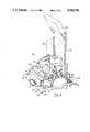
- FIG. 1is a perspective view of a preferred automatic carpet-treating apparatus in accordance with this invention.
- FIG. 2is a fragmentary side elevation of the device in FIG. 1 with the shroud removed and other functional elements removed for improved clarity.
- FIG. 3is a top plan view of FIG. 2.
- FIG. 4is a perspective view with the shroud removed, taken from a position behind the apparatus as shown in FIG. 1.
- FIG. 5is a fragmentary perspective view of FIG. 4, illustrating the surface-traversing elements.
- FIG. 6is a right-side elevation of FIG. 2.
- FIG. 7is another right-side elevation as in FIG. 6, but illustrating the apparatus during a side-stepping motion.
- the figuresillustrate an automatic surface-treating apparatus 10, which is an automaic carpet cleaner in accordance with a preferred embodiment of this invention.
- automatic carpet-cleaning apparatus 10includes a frame 12 which is a box-like rectangular metal band with open top and bottom. Each of the functional elements and assemblies of surface-treating apparatus 10 are secured directly or indirectly to frame 12. Such functional elements and assemblies are then covered by a shroud 14, as shown in FIG. 1, which is secured to frame 12 by means not shown.
- Automatic carpet-cleaning apparatus 10includes a set of mobility members by which apparatus 10 rolls during carpet-cleaning operations.
- the mobility membersinclude a pair of large drive wheels 16 rotatably secured to frame 12 for rotation about a principal drive axis.
- Other mobility membersinclude front and rear balance rollers 18 and 20, each of which rotates about an axis parallel to the principal drive axis. All of such axes extend in a first horizontal direction and during carpet-cleaning operations the main movement of automatic carpet cleaner 10 is either forward or reverse in a direction 90 degrees to such axes.
- Such movementis imparted to carpet-cleaning apparatus 10 by a pair of reversible geared drive motors 22, each of which is linked by gears (not shown) to one of the drive wheels 16.
- Drive motors 22are actuated together for straight-line movement of automatic carpet cleaner 10, either in a forward direction or a reverse direction as dictated by a control means.
- Drive motors 22can be operated at slightly different rates from one another in response to sensors (not shown), in order to keep carpet-cleaning apparatus 10 moving in a straight line. While a pair of drive motors is preferred for drive wheel 16, a single drive motor driving both wheels 16 is an alternative.
- a set of four side-step members 24are rotatably secured with respect to frame 12 at positions near the four corners of frame 12.
- Side-step members 24are all exactly congruent, that is, identical to each other in every dimension and in the location of their center points.
- Side-step members 12are what will be referred herein for convenience as "cut-off wheels.”
- Cut-off wheels 24are oriented 90 degrees offset from the orientation of drive wheels 16, and are rotatable about horizontal axes which are set at 90 degrees to the principal drive axes previously mentioned.
- the horizontal axes of cut-off wheels 24are each positioned a first reference distance above surface 60, the surface on which automatic carpet-cleaning 10 rests.
- Cut-off wheels 24each have a first sector 26 with a far periphery 28 which is spaced from the axis of such cut-off wheel by more than the first reference distance. Each cut-off wheel 24 also has a second sector 30 with a near periphery 32 which is spaced from such axis by less than the first reference distance. This shape for each cut-off wheels 24 and the fact that cut-off wheels 24 act in unison allow cut-off wheels 24 to either be in contact or not in contact with surface 60.
- carpet-cleaning apparatus 10is lifted such that drive wheels 16 and front and rear balance rollers 18 and 20 are above surface 60 and apparatus 10 is moved laterally by a predetermined distance equal to the equal lengths of far peripheries 28.
- Such side-stepping motionwill be described hereafter in greater detail.
- Each cut-off wheel 24is substantially circular except for its near periphery 32 in its second sector 30.
- first sector far periphery 28extends along a substantially circular path and second sector near periphery departs from such circular path.
- each near periphery 32follows a chord of the circle to close the substantially circular path of far periphery 28.
- near periphery 32is a substantially flat surface.
- Far peripheries 28 of cut-off wheels 24extend through arcs of about 220 degrees. Far peripheries with arcs in excess of 180 degrees are highly preferred. It is essential, of course, that flat surfaces 32 be spaced enough above the carpet surface to avoid any interference with such surface or, more specifically, with the carpet pile. It is also essential that, when cut-off wheels 24 have been rotated such that they are supporting apparatus 10, drive wheels 16 and front and rear balance rollers 18 and 20 be enough above the carpet to avoid interference during side-stepping lateral movements of apparatus 10.
- pairs of cut-off wheels 24are affixed to opposite ends of two rods 34.
- Each of the rods 34is rotationally supported in a pair of bearings, including a bearing 36 secured to the side of frame 12 and a bearing 37 secured to a bar 33 which is affixed to frame 12. Rotation of rods 34 within such bearings causes rotation of cut-off wheels 24.
- Cut-off wheel drive motor 38is a geared motor which is secured to frame 17. Geared motor 38 turns one of the rods 34 through a sprocket-chain linkage 40. Another sprocket-chain linkage 42 links the two rods 34 such that they turn in unison in response to the operation of cut-off wheel drive motor 38.
- Cut-off wheel drive motor 38is reversible, such that cut-off wheels 24 may be rotated in one direction for lateral movement to the right and in the other direction for lateral movement to the left.
- the combination of elements and assemblies of the carpet-cleaning meansinclude: a cleaning drive motor 44 which is secured to a cross member (not shown) of frame 12; a blower 46 which is secured to the drive shaft of motor 44; a rotary brush 48 which is rotatably supported between the side walls of frame 12; a gear box 50 which includes a reduction gear arrangement which links motor 44 with a sprocket-chain linkage 52 for rotating brush 48; a foam-producing gear arrangement which links motor 44 with a sprocket-chain linkage 52 for rotating brush 48; a foam-producing unit 54 secured to frame 12 immediately above rotary brush 48; a removable liquid-supply tank 56 (shown in phantom lines) which supplies a foamable liquid to foam-producing unit 54 by means of a hose (not shown); a solenoid valve (not shown) in the liquid supply line to start and stop the flow of carpet-cleaning liquid; a vacuum shoe 58 secured with respect to frame 12 near surface 60 at a position immediately behind
- the operation of the carpet-cleaning meansis as follows:
- cleaning drive motoris actuated to start rotation of brush 48.
- liquid from supply tank 56reaches foam-producing unit 54, the details of which need not be described, upon opening of the solenoid valve, and a foam reaches the carpet beneath apparatus 10 in the area of brush 48.
- Foam productionis aided by exhaust air from drive motor 44 which is transmitted from motor 44 to foam-producing unit 54 by means of hose 68.
- Waste collection unit 64includes a defoaming agent, which allows the waste to collect as a dirty liquid in waste collection unit 64.
- Controller 70includes electronic timers, switches, memory devices and sequencers, all as widely available and well-known. An operator can program the movements and operations of apparatus 10 and can create, revise, store and use several different operational sequences.
- cleaning drive motor 44when apparatus 10 is turned on, cleaning drive motor 44 operates continuously, turning rotary brush 48 and providing the necessary vacuum.
- a signalwill be sent to the aforementioned solenoid to begin the flow of liquid to foam-producing unit 54.
- controller 70After some foam has reached the carpet, a program signal from controller 70 will operate drive motors 16 so that automatic carpet-cleaning apparatus 10 moves in a forward direction. As this occurs, vacuum shoe 58 will remove foam and dirt from the carpet and foam will continue to be applied by means of foam-producing unit 54 and rotary brush 48.
- controller 70Forward movement will continue for a programmer distance which has been set in controller 70.
- the production of foamcan be cut off by closing of the solenoid valve shortly before forward movement ends such that all or substantially all of the foam and dirt will be removed before forward motion stops.
- controller 70will send another signal to drive motors 22, causing it to operate in the reverse direction such that apparatus 10 retraces its path. During such retracing movement, the vacuum unit continues to operate removing any remaining foam from the carpet.
- control unit 70will stop the reverse operation of drive motors 22 and actuate cut-off wheel drive motor 38. Opertion of drive motor 38 wil cause cut-off wheels 24 to make one full revolution in one direction. During such revolution, far peripheries 28 of cut-off wheels 24 will engage surface 60, thus lifting drive wheels 16 and front and rear balance rollers 18 and 20 from surface 60 such that apparatus 10 is supported entirely by cut-off wheels 24. This movement is illustrated in FIG. 7. Continued rotation moves apparatus 10 laterally by a distance equal to the circumferential lengths of far peripheries 28.
- apparatus 10will be lowered until drive wheels 16 and front and rear balance rollers 18 re-engage surface 60, as illustrated in FIG. 6.
- the length of far peripheries 28 and the width of the cleaning path, that is, the width of rotary brush 48,are chosen such that lateral movement of apparatus 10 will not move brush 48 beyond the edge of the path which has been cleaned during a first cleaning stroke.
- the sequences already describedcan be repeated, thus causing apparatus 10 to clean carpet in a slightly-overlapping parallel path adjoining the first path of cleaning.
- Programmable controller 70includes a control panel 72 with control buttons allowing digital programming.
- Control panel 72as illustrated in FIG. 4, is supported by upright structural members 76.
- Also attached to upright structural members 76are a pair of handles 78 which may be used for manual adjustment of the position of automatic carpet-cleaning apparatus 10, as necessary.
- shroud 14includes a door 74 which may be opened to provide access to internal elements.
- removel of door 74allows easy removal and replacement of liquid supply tank 56 and waste collection unit 64. The entire shroud can be removed easily, when servicing is necessary.
- the apparatus of this inventioncan be made using materials and devices which are well-known and available to those skilled in the art.
Landscapes
- Cleaning In General (AREA)
Abstract
Description
This invention is related generally to automatic apparatus for the treatment of horizontal surfaces and, more particularly, to surface-treating apparatus of the type supported by, traversing, and treating horizontal surfaces, primarily carpeted floors, unattended by an operator.
Various devices and methods have been developed in the past for the treatment of horizontal surfaces such as floors. Improving and accelerating floor cleaning operations, particularly by various kinds of automation, have been concerns as long as floors have been cleaned. Because floor-cleaning and similar surface-treating operations are rather labor intensive, substantial cost savings may be available from automation.
With the explosive growth in the use of tack-down carpets in recent years, improving the quality and efficiency of carpet-cleaning operations has become a particular concern. While caring for carpets is generally no more costly than caring for hard floor, carpet care presents a number of unique problems due to the nature of the carpet surface.
For example, a carpeted surface is fibrous, thick and a bit irregular when compared to a flat hard floor; the path of a wheeled device traversing carpet can be affected by these qualities. And, carpet cleaning other than simple vacuuming can involve a number of steps complicating automation.
In the past, a number of devices referred to as "automatic" have been developed for treatment of horizontal surfaces, including in some cases carpets. Many of these devices are "automatic" in the sense that they interact with the surface beneath them without the direct manipulation of brushes, scrubbers, or nozzles by operators, even though operators constantly attend such devices by pushing or guiding them.
Some prior automatic floor-treating devices are "automatic" in the additional sense that they may operate unattended, that is, without an operator beside them to push or otherwise guide them. Among such prior devices are those disclosed in U.S. Pat. Nos. 4,503,581 (Early) and 1,935,158 (Lumley). Such devices traverse the floor under their own power and control. This invention is an improvement in surface-treating equipment of this more fully automatic type, and most specifically an improvement in carpet-cleaning equipment.
Automatic surface-treating equipment of the prior art has a number of problems and shortcomings. More specifically, improved automatic carpet-cleaning equipment is needed.
Automatic carpet-cleaning or floor-cleaning devices typically perform a number of functions as they pass over the carpet or other floor surface to be cleaned. Such functions may include applying a cleaning composition, scrubbing in some manner, and removing the dirt and used cleaning composition.
Such multiple steps may be carried out in a single pass or more then one pass along a first path. After the first path has been treated, it is necessary to repeat the same step or steps along a second path which is parallel to the first path. It is very important that the second path be contiguous with the first path so that there are no neglected strips between the paths.
In particular, there is a tendency for such apparatus to move over a floor in a somewhat erratic or insufficiently controlled manner, particularly when moving from one straight path to the adjacent, or next straight path. Some prior devices have means for lateral movement to a new parallel path. However, such devices are complex in construction and by their nature may be prone to inaccurate movement. Successful treatment of large surface areas without leaving gaps is most difficult. In carpet cleaning operations, it is particularly important that gaps between cleaning paths be avoided.
Some prior automatic unattended devices for treating horizontal surfaces are by their nature suited primarily to use on hard surfaces. The irregularity of carpet surfaces complicates lateral movement. Improved equipment is used for accurate traversing of carpeted surfaces during automatic cleaning operations.
Automatic carpet-cleaning devices, because of the many steps typically necessary as mentioned above, require considerable space for the carpet-cleaning elements and assemblies which must be included. Certain automatic devices of the prior art, because of the apparatus they require for floor-traversing and side-stepping movements, do not provide much space on the for carpet-cleaning elements and assemblies. Improved equipment is needed which provides not only accuracy in movements, including side-stepping movements, but ample room for the elements and assemblies needed for thorough carpet cleaning.
There has been a long-standing need for practical, easily usable and programmable surface-treating apparatus which can dramatically cut labor costs in operations such as carpet cleaning. There is a need for equipment with improved accuracy in its surface-traversing movements even on surfaces such as carpets.
It is an object of this invention to provide an improved automatic surface-treating apparatus overcoming some of the problems and shortcomings of the prior art, including those mentioned above.
Another object of this invention is to provide an improved fully automatic surface-treating device which can cut labor costs in tasks such as carpet cleaning.
Another object of this invention is to provide an improved automatic surface-treating apparatus having accurate surface-traversing movements even though unattended by an operator.
Another object of this invention is to provide an improved surface-treating apparatus which can accurately side-step from one surface-treatment path to the next.
Another object of this invention is to provide an improved automatic surface-treating apparatus which is programmable by an operator such that it properly carries out carpet-cleaning operations or other surface-treating operations.
These and other important objects will be apparent from the descriptions of this invention which follow.
This invention is an automatic surface-treating apparatus of the type supported by and traversing a horizontal surface unattended. The invention is an improvement which overcomes shortcomings of the prior art.
More specifically, the invention is a simple device which has an inherently accurate side-stepping ability; this provides improved accuracy in its surface-traversing movements. The device is also simple in construction such that it provides ample space for surface-treating elements and assemblies, such as those necessary for carpet cleaning. The invention is particularly useful as an automatic unattended carpet-cleaning apparatus.
The automatic surface-cleaning apparatus of this invention includes: a frame; mobility members such as wheels or tracks on the frame which are rotatable about axes extending in a first horizontal direction; means on the frame for treating the surface as the apparatus automatically traverses the surface; and side-step members on the frame which are rotatable about horizontal axes oriented transverse to the first direction and located a given distance about the surface.
Each side-step member has a first sector and a second sector, both of which are important to the manner in which the invention operates. This first sector has what is referred to herein as a far periphery which is spaced from its axis by more than the given distance, that is, by more than the distance by which the side-step axes are above the surface on which the apparatus is supported. The second sector, in contrast, has what is referred to herein as a near periphery, the near periphery being spaced from its axis by less than the aforementioned given distance.
This configuration of the side-step members and the spacing of their axes a given distance above the surface cause the rotation of the side-step members to lift and move the apparatus laterally by a predetermined distance each time they rotate a full turn. As soon as the so-called far peripheries of the side-step members engage the surface, the entire apparatus is gently and accurately lifted so that the main wheels (or other mobility members) leave the surface and the side-step members replace them as support for the apparatus.
The continued turning of such side-step members moves the apparatus sideways by an amount equal to the circumferential lengths of the far peripheries, after which the apparatus is lowered gently until its main wheels (or other mobility members) again bear the weight of the apparatus. The lateral movement provided by such side-step members is very accurate. The extent of such lateral movement may be coordinated with the width of the surface-treating elements of the apparatus, so that no gaps in coverage occur during a surface treatment involving many parallel paths of movement of the surface-treating apparatus.
In preferred embodiments of this invention, the side-step members are oriented such that their axes of rotation are perpendicular to the rotation axes of the mobility members. There are preferably four side-step members in a substantially rectangular arrangement.
The side-step members preferably have congruent profiles and center points, such that the directional orientation of the apparatus is maintained during lateral movement caused by rotation of such members. A single drive is preferably linked to all of the side-step members. This helps to maintain the desired directional orientation of the apparatus during its lateral movement.
The side-step members are preferably cut-off circular wheels. More specifically, their first sector far peripheries extend along a substantially circular path and their second sector near peripheries depart from such circular path. In a highly preferred embodiment, in profile, the near periphery of each such cut-off wheel follows a chord to close the circular path of the far periphery. Thus, the near periphery is substantially flat. When the side-step members are not in use, such flat near peripheries are parallel to the surface. The cut-off wheels preferably have far peripheries which extend along an arc of at least 180 degrees.
In preferred embodiments, the side-step members have far peripheries of length less than the width of the surface-contact members of the apparatus. This allows surface-treatment over multiple parallel paths without gaps, as described above. That is, one turn of the side-step members causes lateral movement of the apparatus to a parallel position not beyond the path last treated.
The mobility members are preferably wheels, as earlier noted, and include at least one drive wheel. A reversible first drive motor is linked to at least one of the drive wheels (or other mobility members), and a preferably reversible second drive motor is linked to the cut-off wheels (or other side-step members). The drive motors are preferably geared motors.
A control means controls the operation of the dirve motors. The control means is programmable such that movements along surface-treatment paths and then to subsequent parallel paths may be set. That is, the path length and apparatus speed may be set before the operation starts and are dictated by the setting of an on-board system. A control panel is included on the apparatus, such panel positioned for easy setting by an operator prior to the start of surface-treating operations. The control panel preferably includes means for digital programming of the apparatus.
This invention is particularly useful for the cleaning of carpets. The device illustrated herein is an automatic carpet-cleaning apparatus. A particularly preferred carpet-cleaning apparatus includes: means on the frame for applying foam to carpet on the surface; a brush movably mounted with respect to the frame in position to stroke the foam through the carpet to loosen carpet soil; means secured to the frame in position adjacent to the brush to vacuum the foam and loosened carpet soil from the carpet; and at least one cleaning drive means, preferably another motor, to drive one or more of the foam applying means, brush and vacuum means. Foam cleaning using such a device has been found to be a particularly effective method for automatic unattended carpet cleaning.
In such an apparatus, the programmable control means is used not only to control the movements of the apparatus across the carpet being cleaned but to control operation of the carpet-cleaning devices as well. Thus, the control means controls several motors used for at least three different purposes. Such control means also can be used to control the flow of cleaning composition by means of solenoid valves or the like.
This sort of control allows improvement not only in efficiency of carpet-cleaning operations, but in their thoroughness. Adequate amounts of cleaning composition and adequate time for cleaning steps can be imposed.
FIG. 1 is a perspective view of a preferred automatic carpet-treating apparatus in accordance with this invention.
FIG. 2 is a fragmentary side elevation of the device in FIG. 1 with the shroud removed and other functional elements removed for improved clarity.
FIG. 3 is a top plan view of FIG. 2.
FIG. 4 is a perspective view with the shroud removed, taken from a position behind the apparatus as shown in FIG. 1.
FIG. 5 is a fragmentary perspective view of FIG. 4, illustrating the surface-traversing elements.
FIG. 6 is a right-side elevation of FIG. 2.
FIG. 7 is another right-side elevation as in FIG. 6, but illustrating the apparatus during a side-stepping motion.
The figures illustrate an automatic surface-treatingapparatus 10, which is an automaic carpet cleaner in accordance with a preferred embodiment of this invention.
As illustrated in FIGS. 2-4, 6 and 7, automatic carpet-cleaningapparatus 10 includes aframe 12 which is a box-like rectangular metal band with open top and bottom. Each of the functional elements and assemblies of surface-treatingapparatus 10 are secured directly or indirectly to frame 12. Such functional elements and assemblies are then covered by ashroud 14, as shown in FIG. 1, which is secured to frame 12 by means not shown.
Automatic carpet-cleaningapparatus 10 includes a set of mobility members by whichapparatus 10 rolls during carpet-cleaning operations. The mobility members include a pair oflarge drive wheels 16 rotatably secured to frame 12 for rotation about a principal drive axis. Other mobility members include front andrear balance rollers automatic carpet cleaner 10 is either forward or reverse in a direction 90 degrees to such axes.
Such movement is imparted to carpet-cleaningapparatus 10 by a pair of reversible geareddrive motors 22, each of which is linked by gears (not shown) to one of thedrive wheels 16. Drivemotors 22 are actuated together for straight-line movement ofautomatic carpet cleaner 10, either in a forward direction or a reverse direction as dictated by a control means. Drivemotors 22 can be operated at slightly different rates from one another in response to sensors (not shown), in order to keep carpet-cleaningapparatus 10 moving in a straight line. While a pair of drive motors is preferred fordrive wheel 16, a single drive motor driving bothwheels 16 is an alternative.
A set of four side-step members 24 are rotatably secured with respect to frame 12 at positions near the four corners offrame 12. Side-step members 24 are all exactly congruent, that is, identical to each other in every dimension and in the location of their center points. Side-step members 12 are what will be referred herein for convenience as "cut-off wheels."
Cut-offwheels 24 are oriented 90 degrees offset from the orientation ofdrive wheels 16, and are rotatable about horizontal axes which are set at 90 degrees to the principal drive axes previously mentioned. The horizontal axes of cut-offwheels 24 are each positioned a first reference distance abovesurface 60, the surface on which automatic carpet-cleaning 10 rests.
Cut-offwheels 24 each have afirst sector 26 with afar periphery 28 which is spaced from the axis of such cut-off wheel by more than the first reference distance. Each cut-off wheel 24 also has asecond sector 30 with anear periphery 32 which is spaced from such axis by less than the first reference distance. This shape for each cut-offwheels 24 and the fact that cut-offwheels 24 act in unison allow cut-offwheels 24 to either be in contact or not in contact withsurface 60.
By a single 360-degree rotation of cut-offwheels 24, carpet-cleaningapparatus 10 is lifted such thatdrive wheels 16 and front andrear balance rollers surface 60 andapparatus 10 is moved laterally by a predetermined distance equal to the equal lengths of far peripheries 28. Such side-stepping motion will be described hereafter in greater detail.
Each cut-off wheel 24 is substantially circular except for itsnear periphery 32 in itssecond sector 30. Thus, first sectorfar periphery 28 extends along a substantially circular path and second sector near periphery departs from such circular path. Indeed, in profile, eachnear periphery 32 follows a chord of the circle to close the substantially circular path offar periphery 28. Thus, nearperiphery 32 is a substantially flat surface. When cut-offwheels 24 are not performing their side-stepping function, they are held in an orientation such thatflat surfaces 32 are substantially parallel to and spaced fromsurface 60. This is shown best in FIGS. 2 and 4-6.
As shown best in FIG. 5, pairs of cut-offwheels 24 are affixed to opposite ends of tworods 34. Each of therods 34 is rotationally supported in a pair of bearings, including abearing 36 secured to the side offrame 12 and abearing 37 secured to abar 33 which is affixed to frame 12. Rotation ofrods 34 within such bearings causes rotation of cut-offwheels 24.
Such rotation is imparted to all four cut-offwheels 24 by asingle drive motor 38. Cut-offwheel drive motor 38 is a geared motor which is secured to frame 17.Geared motor 38 turns one of therods 34 through a sprocket-chain linkage 40. Another sprocket-chain linkage 42 links the tworods 34 such that they turn in unison in response to the operation of cut-offwheel drive motor 38.
Such unison operation of all four cut-offwheels 24 allows the directional orientation of carpet-cleaningapparatus 10 to be maintained during the lateral motion which is imparted toapparatus 10 by rotation of such cut-off wheels. Cut-offwheel drive motor 38 is reversible, such that cut-offwheels 24 may be rotated in one direction for lateral movement to the right and in the other direction for lateral movement to the left.
Control of the operation of cut-offwheels 24, including coordination with the operation ofdrive wheels 16, will be described hereafter in greater detail. First however, the surface-treating devices shown in the drawings will be described. In this case, such devices are for carpet-cleaning, and, more specifically, carpet cleaning using a foam-cleaning method.
As shown best in FIG. 4, the combination of elements and assemblies of the carpet-cleaning means include: a cleaning drive motor 44 which is secured to a cross member (not shown) of frame 12; a blower 46 which is secured to the drive shaft of motor 44; a rotary brush 48 which is rotatably supported between the side walls of frame 12; a gear box 50 which includes a reduction gear arrangement which links motor 44 with a sprocket-chain linkage 52 for rotating brush 48; a foam-producing gear arrangement which links motor 44 with a sprocket-chain linkage 52 for rotating brush 48; a foam-producing unit 54 secured to frame 12 immediately above rotary brush 48; a removable liquid-supply tank 56 (shown in phantom lines) which supplies a foamable liquid to foam-producing unit 54 by means of a hose (not shown); a solenoid valve (not shown) in the liquid supply line to start and stop the flow of carpet-cleaning liquid; a vacuum shoe 58 secured with respect to frame 12 near surface 60 at a position immediately behind rotary brush 48; a vacuum hose 62 leading from vacuum shoe 58 to blower 46; a removable waste collection unit 64 supported toward the back of apparatus 10; and a waste transmission hose 66 extending from blower 46 to collection unit 64.
The operation of the carpet-cleaning means is as follows:
First, cleaning drive motor is actuated to start rotation ofbrush 48. Then, liquid from supply tank 56 reaches foam-producingunit 54, the details of which need not be described, upon opening of the solenoid valve, and a foam reaches the carpet beneathapparatus 10 in the area ofbrush 48. Foam production is aided by exhaust air from drive motor 44 which is transmitted from motor 44 to foam-producingunit 54 by means of hose 68.
The rotation ofbrush 48 in a counter-clockwise direction (as viewed in FIG. 4), strokes the foam into and through the carpet pile to quickly remove dirt from carpet fibers. After foam application has begun, forward movement ofapparatus 10 may begin. As this occurs, the vacuum produced invacuum shoe 58 byblower 46 pulls the foam and dirt from the carpet, between the carpet fibers, and transmits such foam and dirt throughvacuum hose 62,blower 46, andwaste transmission hose 66 to wastecollection unit 64.Waste collection unit 64 includes a defoaming agent, which allows the waste to collect as a dirty liquid inwaste collection unit 64.
A variety of other carpet-cleaning devices could be used instead of the device which is illustrated. Or, the automatic unattended surface-treating apparatus of this invention can be used for other purposes.
The operations ofdrive motors 22, drivemotor 38, drive motor 44, and the aforementioned solenoid valve are all controlled and coordinated by aprogrammable controller 70, shown in FIGS. 1 and 4.Controller 70 includes electronic timers, switches, memory devices and sequencers, all as widely available and well-known. An operator can program the movements and operations ofapparatus 10 and can create, revise, store and use several different operational sequences.
In the illustrated embodiment, whenapparatus 10 is turned on, cleaning drive motor 44 operates continuously, turningrotary brush 48 and providing the necessary vacuum. In one sequence of events, a signal will be sent to the aforementioned solenoid to begin the flow of liquid to foam-producingunit 54. After some foam has reached the carpet, a program signal fromcontroller 70 will operate drivemotors 16 so that automatic carpet-cleaningapparatus 10 moves in a forward direction. As this occurs,vacuum shoe 58 will remove foam and dirt from the carpet and foam will continue to be applied by means of foam-producingunit 54 androtary brush 48.
Forward movement will continue for a programmer distance which has been set incontroller 70. The production of foam can be cut off by closing of the solenoid valve shortly before forward movement ends such that all or substantially all of the foam and dirt will be removed before forward motion stops. Then,controller 70 will send another signal to drivemotors 22, causing it to operate in the reverse direction such thatapparatus 10 retraces its path. During such retracing movement, the vacuum unit continues to operate removing any remaining foam from the carpet.
After such reverse movement for a programmed distance equal to the forward movement,control unit 70 will stop the reverse operation ofdrive motors 22 and actuate cut-offwheel drive motor 38. Opertion ofdrive motor 38 wil cause cut-offwheels 24 to make one full revolution in one direction. During such revolution, far peripheries 28 of cut-offwheels 24 will engagesurface 60, thus liftingdrive wheels 16 and front andrear balance rollers surface 60 such thatapparatus 10 is supported entirely by cut-offwheels 24. This movement is illustrated in FIG. 7. Continued rotation movesapparatus 10 laterally by a distance equal to the circumferential lengths of far peripheries 28.
As the one full rotation of cut-offwheels 24 ends,apparatus 10 will be lowered untildrive wheels 16 and front andrear balance rollers 18re-engage surface 60, as illustrated in FIG. 6. The length offar peripheries 28 and the width of the cleaning path, that is, the width ofrotary brush 48, are chosen such that lateral movement ofapparatus 10 will not movebrush 48 beyond the edge of the path which has been cleaned during a first cleaning stroke. Afterapparatus 10 has been moved, as described, the sequences already described can be repeated, thus causingapparatus 10 to clean carpet in a slightly-overlapping parallel path adjoining the first path of cleaning.
Referring again to FIG. 1, it can be seen thatshroud 14 includes adoor 74 which may be opened to provide access to internal elements. In particular, removel ofdoor 74 allows easy removal and replacement of liquid supply tank 56 andwaste collection unit 64. The entire shroud can be removed easily, when servicing is necessary.
The apparatus of this invention can be made using materials and devices which are well-known and available to those skilled in the art.
While the principles of this invention have been described in connection with specific embodiments, it should be understood clearly that these decriptions are made only by way of example and are not intended to limit the scope of the invention.
Claims (19)
1. Automatic surface-treating apparatus of the type supported by and traversing a horizontal surface unattended, comprising:
a frame;
mobility members on the frame rotatable about axes extending in a first horizontal direction;
means on the frame fo treating the surface as the apparatus traverses the surface;
side-step members on the frame rotatable about horizontal axes transverse to the first direction and a given distance above the surface, each side-step member having:
a first sector with a far periphery spaced from its axis by more than the given distance, and
a second sector with a near periphery spaced from its axis by less than the given distance;
whereby rotation of the side-step members will lift and move the apparatus laterally a predetermined distance.
2. The automatic surface-treating apparatus of claim 1 wherein the axes of side-step member rotation are perpendicular to the rotation axes of the mobility members.
3. The automatic surface-treating apparatus of claim 1 wherein there are four side-step members in a substantially rectangular arrangement.
4. The automatic surface-treating apparatus of claim 1 wherein the side-step members have congruent profiles and center points, whereby the directional orientation of the apparatus is maintained during lateral movement caused by rotation of such members.
5. The automatic surface-treating apparatus of claim 4 further including a single side-step drive unit and means connecting such drive unit to all side-step members, whereby the directional orientation of the apparatus is maintained during laterl movement caused by rotation of such members.
6. The automatic surface-treating apparatus of claim 4 wherein, in the side-step member profile, the first sector far periphery extends along a substantially circular path and the second sector near periphery departs from such circular path.
7. The automatic surface-treating apparatus of claim 6 wherein, in profile, the near periphery follows a chord to close the substantially circular path such that the near periphery is substantially flat and, when the side-step members are not in use, substantially parallel to the surface.
8. The automatic surface-treating apparatus of claim 6 wherein the far periphery extends along an arc of at least 180 degrees.
9. The automatic surface-treating apparatus of claim 1 wherein:
the surface-treating means includes surface-contact members of a first width such that a path of first width is treated as the apparatus traverses the surface on its mobility members; and
the side-step members have far peripheries of length less than said first width,
whereby one rotation of the side-step members moves the apparatus laterally to a parallel position not beyond the path already treated.
10. The automatic surface-treating apparatus of claim 1 wherein mobility members are wheels, including at least one drive wheel.
11. The automatic surface-treating apparatus of claim 1 further including:
a reversible first drive means linked to at least one of the mobility members;
a second drive means linked to the side-step members; and
means to control operation of the drive means thereby to control straight and lateral movements of the apparatus.
12. The automatic surface-treating apparatus of claim 11 wherein the control means comprises programmable control means.
13. The automatic surface-treating apparatus of claim 12 further comprising a control panel including means for digital programming of the apparatus prior to operation.
14. The automatic surface-treating apparatus of claim 12 wherein the first and second drive means include geared motors.
15. The automatic surface-treating apparatus of claim 1 wherein the surface-treating means comprises means for cleaning carpets.
16. The automatic surface-treating apparatus of claim 15 wherein the carpet-cleaning means comprises:
means on the frame for applying foam to carpet on the surface;
a brush movably mounted with respect to the frame in position to stroke the foam through the carpet to loosen carpet soil;
means secured to the frame in position adjacent to the brush to vacuum the foam and loosened carpet soil from the carpet; and
at least one cleaning drive means to drive one or more of the foam applying means, brush and vacuum means.
17. The automatic surface-treating apparatus of claim 16 further including:
a reversible first drive means linked to at least one of the mobility members;
a second drive means linked to the side-step members; and
means to control operation of the plural drive means thereby to control straight and lateral movements of the apparatus and its cleaning operations.
18. The automatic surface-treating apparatus of claim 17 wherein the control means comprises programmable control means.
19. The automatic surface-treating apparatus of claim 18 further comprising a control panel including means for digital programming of the apparatus prior to operation.
Priority Applications (3)
| Application Number | Priority Date | Filing Date | Title |
|---|---|---|---|
| US07/155,312US4782550A (en) | 1988-02-12 | 1988-02-12 | Automatic surface-treating apparatus |
| PCT/US1988/003829WO1990004349A1 (en) | 1988-02-12 | 1988-10-27 | Improved automatic surface-treating apparatus |
| CA000581906ACA1303305C (en) | 1988-02-12 | 1988-11-01 | Automatic surface-treating apparatus |
Applications Claiming Priority (1)
| Application Number | Priority Date | Filing Date | Title |
|---|---|---|---|
| US07/155,312US4782550A (en) | 1988-02-12 | 1988-02-12 | Automatic surface-treating apparatus |
Publications (1)
| Publication Number | Publication Date |
|---|---|
| US4782550Atrue US4782550A (en) | 1988-11-08 |
Family
ID=22554923
Family Applications (1)
| Application Number | Title | Priority Date | Filing Date |
|---|---|---|---|
| US07/155,312Expired - Fee RelatedUS4782550A (en) | 1988-02-12 | 1988-02-12 | Automatic surface-treating apparatus |
Country Status (3)
| Country | Link |
|---|---|
| US (1) | US4782550A (en) |
| CA (1) | CA1303305C (en) |
| WO (1) | WO1990004349A1 (en) |
Cited By (65)
| Publication number | Priority date | Publication date | Assignee | Title |
|---|---|---|---|---|
| WO1990014788A1 (en)* | 1989-06-07 | 1990-12-13 | Onet | Process and autonomous apparatus for the automatic cleaning of ground areas through the performance of programmed tasks |
| US5038484A (en)* | 1989-07-14 | 1991-08-13 | Von Schrader Company | Apparatus for determining an area coverage rate |
| WO1992000500A1 (en)* | 1989-07-14 | 1992-01-09 | Von Schrader Company | Apparatus for determining an area coverage rate |
| US5095577A (en)* | 1986-12-11 | 1992-03-17 | Azurtec | Automatic vacuum cleaner |
| FR2695342A1 (en)* | 1989-06-07 | 1994-03-11 | Onet | Robotic floor-sweeping with stored-program microprocessor control |
| EP0584888A3 (en)* | 1989-06-07 | 1994-09-14 | Onet Sa | Autonomous apparatus and process for the automatic cleaning of ground areas through performance of programmed tasks |
| EP0666052A1 (en)* | 1994-02-03 | 1995-08-09 | AEG Hausgeräte GmbH | Floor cleaning machine |
| US5542147A (en)* | 1995-05-02 | 1996-08-06 | Bissell Inc. | Spray suction and agitator control and deep cleaning machine |
| US5709007A (en)* | 1996-06-10 | 1998-01-20 | Chiang; Wayne | Remote control vacuum cleaner |
| US5815880A (en)* | 1995-08-08 | 1998-10-06 | Minolta Co., Ltd. | Cleaning robot |
| US6105192A (en)* | 1998-03-30 | 2000-08-22 | Alto U. S., Inc. | Solenoid valve and timing module for a floor treating apparatus |
| US6459955B1 (en) | 1999-11-18 | 2002-10-01 | The Procter & Gamble Company | Home cleaning robot |
| US6481515B1 (en)* | 2000-05-30 | 2002-11-19 | The Procter & Gamble Company | Autonomous mobile surface treating apparatus |
| US6580246B2 (en)* | 2001-08-13 | 2003-06-17 | Steven Jacobs | Robot touch shield |
| US20040200505A1 (en)* | 2003-03-14 | 2004-10-14 | Taylor Charles E. | Robot vac with retractable power cord |
| US20040211444A1 (en)* | 2003-03-14 | 2004-10-28 | Taylor Charles E. | Robot vacuum with particulate detector |
| US20040220698A1 (en)* | 2003-03-14 | 2004-11-04 | Taylor Charles E | Robotic vacuum cleaner with edge and object detection system |
| US20050000543A1 (en)* | 2003-03-14 | 2005-01-06 | Taylor Charles E. | Robot vacuum with internal mapping system |
| US20050010331A1 (en)* | 2003-03-14 | 2005-01-13 | Taylor Charles E. | Robot vacuum with floor type modes |
| US6941199B1 (en) | 1998-07-20 | 2005-09-06 | The Procter & Gamble Company | Robotic system |
| US20050231068A1 (en)* | 2004-03-31 | 2005-10-20 | Sanyo Electric Co., Ltd. | Transmitting apparatus, sound sensor and autonomous traveling vehicle |
| WO2006089307A3 (en)* | 2005-02-18 | 2006-11-23 | Irobot Corp | Autonomous surface cleaning robot for wet and dry cleaning |
| US20060293809A1 (en)* | 2005-06-28 | 2006-12-28 | Harwig Jeffrey L | Methods to prevent wheel slip in an autonomous floor cleaner |
| US20080134457A1 (en)* | 2005-02-18 | 2008-06-12 | Irobot Corporation | Autonomous surface cleaning robot for dry cleaning |
| US7389156B2 (en) | 2005-02-18 | 2008-06-17 | Irobot Corporation | Autonomous surface cleaning robot for wet and dry cleaning |
| US7388343B2 (en) | 2001-06-12 | 2008-06-17 | Irobot Corporation | Method and system for multi-mode coverage for an autonomous robot |
| US7430455B2 (en) | 2000-01-24 | 2008-09-30 | Irobot Corporation | Obstacle following sensor scheme for a mobile robot |
| US7441298B2 (en) | 2005-12-02 | 2008-10-28 | Irobot Corporation | Coverage robot mobility |
| US7448113B2 (en) | 2002-01-03 | 2008-11-11 | Irobert | Autonomous floor cleaning robot |
| US7459871B2 (en) | 2004-01-28 | 2008-12-02 | Irobot Corporation | Debris sensor for cleaning apparatus |
| US7567052B2 (en) | 2001-01-24 | 2009-07-28 | Irobot Corporation | Robot navigation |
| EP2248454A1 (en)* | 2009-05-08 | 2010-11-10 | Infrasport AG | Fully automatic method for cleaning sports halls and device for carrying out the method |
| US8087117B2 (en) | 2006-05-19 | 2012-01-03 | Irobot Corporation | Cleaning robot roller processing |
| US8239992B2 (en) | 2007-05-09 | 2012-08-14 | Irobot Corporation | Compact autonomous coverage robot |
| US8374721B2 (en) | 2005-12-02 | 2013-02-12 | Irobot Corporation | Robot system |
| US8380350B2 (en) | 2005-12-02 | 2013-02-19 | Irobot Corporation | Autonomous coverage robot navigation system |
| US8386081B2 (en) | 2002-09-13 | 2013-02-26 | Irobot Corporation | Navigational control system for a robotic device |
| US8382906B2 (en) | 2005-02-18 | 2013-02-26 | Irobot Corporation | Autonomous surface cleaning robot for wet cleaning |
| US8390251B2 (en) | 2004-01-21 | 2013-03-05 | Irobot Corporation | Autonomous robot auto-docking and energy management systems and methods |
| US8396592B2 (en) | 2001-06-12 | 2013-03-12 | Irobot Corporation | Method and system for multi-mode coverage for an autonomous robot |
| US20130061417A1 (en)* | 2011-09-09 | 2013-03-14 | Dyson Technology Limited | Autonomous cleaning appliance |
| US20130061416A1 (en)* | 2011-09-09 | 2013-03-14 | Dyson Technology Limited | Autonomous surface treating appliance |
| US8417383B2 (en) | 2006-05-31 | 2013-04-09 | Irobot Corporation | Detecting robot stasis |
| US8515578B2 (en) | 2002-09-13 | 2013-08-20 | Irobot Corporation | Navigational control system for a robotic device |
| US8584305B2 (en) | 2005-12-02 | 2013-11-19 | Irobot Corporation | Modular robot |
| US8594840B1 (en) | 2004-07-07 | 2013-11-26 | Irobot Corporation | Celestial navigation system for an autonomous robot |
| US8634960B2 (en) | 2006-03-17 | 2014-01-21 | Irobot Corporation | Lawn care robot |
| US8780342B2 (en) | 2004-03-29 | 2014-07-15 | Irobot Corporation | Methods and apparatus for position estimation using reflected light sources |
| US8788092B2 (en) | 2000-01-24 | 2014-07-22 | Irobot Corporation | Obstacle following sensor scheme for a mobile robot |
| US8800107B2 (en) | 2010-02-16 | 2014-08-12 | Irobot Corporation | Vacuum brush |
| US8930023B2 (en) | 2009-11-06 | 2015-01-06 | Irobot Corporation | Localization by learning of wave-signal distributions |
| US8972052B2 (en) | 2004-07-07 | 2015-03-03 | Irobot Corporation | Celestial navigation system for an autonomous vehicle |
| US9008835B2 (en) | 2004-06-24 | 2015-04-14 | Irobot Corporation | Remote control scheduler and method for autonomous robotic device |
| US9320398B2 (en) | 2005-12-02 | 2016-04-26 | Irobot Corporation | Autonomous coverage robots |
| US9420741B2 (en) | 2014-12-15 | 2016-08-23 | Irobot Corporation | Robot lawnmower mapping |
| US9510505B2 (en) | 2014-10-10 | 2016-12-06 | Irobot Corporation | Autonomous robot localization |
| US9516806B2 (en) | 2014-10-10 | 2016-12-13 | Irobot Corporation | Robotic lawn mowing boundary determination |
| US9538702B2 (en) | 2014-12-22 | 2017-01-10 | Irobot Corporation | Robotic mowing of separated lawn areas |
| US9554508B2 (en) | 2014-03-31 | 2017-01-31 | Irobot Corporation | Autonomous mobile robot |
| US9949608B2 (en) | 2002-09-13 | 2018-04-24 | Irobot Corporation | Navigational control system for a robotic device |
| JP2018086423A (en)* | 2005-02-18 | 2018-06-07 | アイロボット コーポレイション | Cleaning robot |
| US10021830B2 (en) | 2016-02-02 | 2018-07-17 | Irobot Corporation | Blade assembly for a grass cutting mobile robot |
| US10459063B2 (en) | 2016-02-16 | 2019-10-29 | Irobot Corporation | Ranging and angle of arrival antenna system for a mobile robot |
| US11115798B2 (en) | 2015-07-23 | 2021-09-07 | Irobot Corporation | Pairing a beacon with a mobile robot |
| US11470774B2 (en) | 2017-07-14 | 2022-10-18 | Irobot Corporation | Blade assembly for a grass cutting mobile robot |
Citations (6)
| Publication number | Priority date | Publication date | Assignee | Title |
|---|---|---|---|---|
| GB336725A (en)* | 1929-08-27 | 1930-10-23 | Mejer Goralski | Improvements in means for turning automobile vehicles in confined spaces |
| US1935158A (en)* | 1929-01-11 | 1933-11-14 | Frank E Lumley | Vacuum cleaner |
| US3142350A (en)* | 1959-09-15 | 1964-07-28 | Ellis G Flint | Motor vehicle parking device mounted on rear axle differential casing |
| US3713505A (en)* | 1970-04-25 | 1973-01-30 | Bosch Gmbh Robert | Automatically steered self propelled vehicle |
| US4114711A (en)* | 1975-01-10 | 1978-09-19 | R. G. Dixon & Company Limited | Floor treating machines |
| US4503581A (en)* | 1983-03-09 | 1985-03-12 | Early Susan E | Automatic floor treating apparatus |
- 1988
- 1988-02-12USUS07/155,312patent/US4782550A/ennot_activeExpired - Fee Related
- 1988-10-27WOPCT/US1988/003829patent/WO1990004349A1/enunknown
- 1988-11-01CACA000581906Apatent/CA1303305C/ennot_activeExpired - Fee Related
Patent Citations (6)
| Publication number | Priority date | Publication date | Assignee | Title |
|---|---|---|---|---|
| US1935158A (en)* | 1929-01-11 | 1933-11-14 | Frank E Lumley | Vacuum cleaner |
| GB336725A (en)* | 1929-08-27 | 1930-10-23 | Mejer Goralski | Improvements in means for turning automobile vehicles in confined spaces |
| US3142350A (en)* | 1959-09-15 | 1964-07-28 | Ellis G Flint | Motor vehicle parking device mounted on rear axle differential casing |
| US3713505A (en)* | 1970-04-25 | 1973-01-30 | Bosch Gmbh Robert | Automatically steered self propelled vehicle |
| US4114711A (en)* | 1975-01-10 | 1978-09-19 | R. G. Dixon & Company Limited | Floor treating machines |
| US4503581A (en)* | 1983-03-09 | 1985-03-12 | Early Susan E | Automatic floor treating apparatus |
Cited By (190)
| Publication number | Priority date | Publication date | Assignee | Title |
|---|---|---|---|---|
| US5095577A (en)* | 1986-12-11 | 1992-03-17 | Azurtec | Automatic vacuum cleaner |
| WO1990014788A1 (en)* | 1989-06-07 | 1990-12-13 | Onet | Process and autonomous apparatus for the automatic cleaning of ground areas through the performance of programmed tasks |
| FR2648071A1 (en)* | 1989-06-07 | 1990-12-14 | Onet | SELF-CONTAINED METHOD AND APPARATUS FOR AUTOMATIC FLOOR CLEANING BY EXECUTING PROGRAMMED MISSIONS |
| FR2695342A1 (en)* | 1989-06-07 | 1994-03-11 | Onet | Robotic floor-sweeping with stored-program microprocessor control |
| US5341540A (en)* | 1989-06-07 | 1994-08-30 | Onet, S.A. | Process and autonomous apparatus for the automatic cleaning of ground areas through the performance of programmed tasks |
| EP0584888A3 (en)* | 1989-06-07 | 1994-09-14 | Onet Sa | Autonomous apparatus and process for the automatic cleaning of ground areas through performance of programmed tasks |
| US5038484A (en)* | 1989-07-14 | 1991-08-13 | Von Schrader Company | Apparatus for determining an area coverage rate |
| WO1992000500A1 (en)* | 1989-07-14 | 1992-01-09 | Von Schrader Company | Apparatus for determining an area coverage rate |
| EP0666052A1 (en)* | 1994-02-03 | 1995-08-09 | AEG Hausgeräte GmbH | Floor cleaning machine |
| US5542147A (en)* | 1995-05-02 | 1996-08-06 | Bissell Inc. | Spray suction and agitator control and deep cleaning machine |
| US5815880A (en)* | 1995-08-08 | 1998-10-06 | Minolta Co., Ltd. | Cleaning robot |
| US5709007A (en)* | 1996-06-10 | 1998-01-20 | Chiang; Wayne | Remote control vacuum cleaner |
| US6105192A (en)* | 1998-03-30 | 2000-08-22 | Alto U. S., Inc. | Solenoid valve and timing module for a floor treating apparatus |
| EP0947900A3 (en)* | 1998-03-30 | 2001-01-03 | Alto U.S. Inc. | Solenoid valve and timing module for a floor treating apparatus |
| US6301738B1 (en) | 1998-03-30 | 2001-10-16 | Alto U.S., Inc. | Solenoid valve and timing module kit for a floor treating apparatus |
| US6941199B1 (en) | 1998-07-20 | 2005-09-06 | The Procter & Gamble Company | Robotic system |
| US20050234612A1 (en)* | 1998-07-20 | 2005-10-20 | The Procter & Gamble Company | Robotic system |
| US6459955B1 (en) | 1999-11-18 | 2002-10-01 | The Procter & Gamble Company | Home cleaning robot |
| US8478442B2 (en) | 2000-01-24 | 2013-07-02 | Irobot Corporation | Obstacle following sensor scheme for a mobile robot |
| US8788092B2 (en) | 2000-01-24 | 2014-07-22 | Irobot Corporation | Obstacle following sensor scheme for a mobile robot |
| US9446521B2 (en) | 2000-01-24 | 2016-09-20 | Irobot Corporation | Obstacle following sensor scheme for a mobile robot |
| US7430455B2 (en) | 2000-01-24 | 2008-09-30 | Irobot Corporation | Obstacle following sensor scheme for a mobile robot |
| US8412377B2 (en) | 2000-01-24 | 2013-04-02 | Irobot Corporation | Obstacle following sensor scheme for a mobile robot |
| US8565920B2 (en) | 2000-01-24 | 2013-10-22 | Irobot Corporation | Obstacle following sensor scheme for a mobile robot |
| US8761935B2 (en) | 2000-01-24 | 2014-06-24 | Irobot Corporation | Obstacle following sensor scheme for a mobile robot |
| US9144361B2 (en) | 2000-04-04 | 2015-09-29 | Irobot Corporation | Debris sensor for cleaning apparatus |
| US6481515B1 (en)* | 2000-05-30 | 2002-11-19 | The Procter & Gamble Company | Autonomous mobile surface treating apparatus |
| US9622635B2 (en) | 2001-01-24 | 2017-04-18 | Irobot Corporation | Autonomous floor-cleaning robot |
| US9038233B2 (en) | 2001-01-24 | 2015-05-26 | Irobot Corporation | Autonomous floor-cleaning robot |
| US9167946B2 (en) | 2001-01-24 | 2015-10-27 | Irobot Corporation | Autonomous floor cleaning robot |
| US8659256B2 (en) | 2001-01-24 | 2014-02-25 | Irobot Corporation | Robot confinement |
| US8659255B2 (en) | 2001-01-24 | 2014-02-25 | Irobot Corporation | Robot confinement |
| US9582005B2 (en) | 2001-01-24 | 2017-02-28 | Irobot Corporation | Robot confinement |
| US7579803B2 (en) | 2001-01-24 | 2009-08-25 | Irobot Corporation | Robot confinement |
| US7567052B2 (en) | 2001-01-24 | 2009-07-28 | Irobot Corporation | Robot navigation |
| US8368339B2 (en) | 2001-01-24 | 2013-02-05 | Irobot Corporation | Robot confinement |
| US8838274B2 (en) | 2001-06-12 | 2014-09-16 | Irobot Corporation | Method and system for multi-mode coverage for an autonomous robot |
| US9104204B2 (en) | 2001-06-12 | 2015-08-11 | Irobot Corporation | Method and system for multi-mode coverage for an autonomous robot |
| US7429843B2 (en) | 2001-06-12 | 2008-09-30 | Irobot Corporation | Method and system for multi-mode coverage for an autonomous robot |
| US8396592B2 (en) | 2001-06-12 | 2013-03-12 | Irobot Corporation | Method and system for multi-mode coverage for an autonomous robot |
| US7388343B2 (en) | 2001-06-12 | 2008-06-17 | Irobot Corporation | Method and system for multi-mode coverage for an autonomous robot |
| US7663333B2 (en) | 2001-06-12 | 2010-02-16 | Irobot Corporation | Method and system for multi-mode coverage for an autonomous robot |
| US8463438B2 (en) | 2001-06-12 | 2013-06-11 | Irobot Corporation | Method and system for multi-mode coverage for an autonomous robot |
| US6580246B2 (en)* | 2001-08-13 | 2003-06-17 | Steven Jacobs | Robot touch shield |
| US7636982B2 (en) | 2002-01-03 | 2009-12-29 | Irobot Corporation | Autonomous floor cleaning robot |
| US7448113B2 (en) | 2002-01-03 | 2008-11-11 | Irobert | Autonomous floor cleaning robot |
| US7571511B2 (en) | 2002-01-03 | 2009-08-11 | Irobot Corporation | Autonomous floor-cleaning robot |
| US8671507B2 (en) | 2002-01-03 | 2014-03-18 | Irobot Corporation | Autonomous floor-cleaning robot |
| US8763199B2 (en) | 2002-01-03 | 2014-07-01 | Irobot Corporation | Autonomous floor-cleaning robot |
| US8656550B2 (en) | 2002-01-03 | 2014-02-25 | Irobot Corporation | Autonomous floor-cleaning robot |
| US8516651B2 (en) | 2002-01-03 | 2013-08-27 | Irobot Corporation | Autonomous floor-cleaning robot |
| US8474090B2 (en) | 2002-01-03 | 2013-07-02 | Irobot Corporation | Autonomous floor-cleaning robot |
| US9128486B2 (en) | 2002-01-24 | 2015-09-08 | Irobot Corporation | Navigational control system for a robotic device |
| US8515578B2 (en) | 2002-09-13 | 2013-08-20 | Irobot Corporation | Navigational control system for a robotic device |
| US9949608B2 (en) | 2002-09-13 | 2018-04-24 | Irobot Corporation | Navigational control system for a robotic device |
| US8793020B2 (en) | 2002-09-13 | 2014-07-29 | Irobot Corporation | Navigational control system for a robotic device |
| US8386081B2 (en) | 2002-09-13 | 2013-02-26 | Irobot Corporation | Navigational control system for a robotic device |
| US20040200505A1 (en)* | 2003-03-14 | 2004-10-14 | Taylor Charles E. | Robot vac with retractable power cord |
| US7805220B2 (en) | 2003-03-14 | 2010-09-28 | Sharper Image Acquisition Llc | Robot vacuum with internal mapping system |
| US7801645B2 (en) | 2003-03-14 | 2010-09-21 | Sharper Image Acquisition Llc | Robotic vacuum cleaner with edge and object detection system |
| US20040236468A1 (en)* | 2003-03-14 | 2004-11-25 | Taylor Charles E. | Robot vacuum with remote control mode |
| US20040244138A1 (en)* | 2003-03-14 | 2004-12-09 | Taylor Charles E. | Robot vacuum |
| US20050000543A1 (en)* | 2003-03-14 | 2005-01-06 | Taylor Charles E. | Robot vacuum with internal mapping system |
| US20040220698A1 (en)* | 2003-03-14 | 2004-11-04 | Taylor Charles E | Robotic vacuum cleaner with edge and object detection system |
| US20040211444A1 (en)* | 2003-03-14 | 2004-10-28 | Taylor Charles E. | Robot vacuum with particulate detector |
| US20050010331A1 (en)* | 2003-03-14 | 2005-01-13 | Taylor Charles E. | Robot vacuum with floor type modes |
| US8390251B2 (en) | 2004-01-21 | 2013-03-05 | Irobot Corporation | Autonomous robot auto-docking and energy management systems and methods |
| US9215957B2 (en) | 2004-01-21 | 2015-12-22 | Irobot Corporation | Autonomous robot auto-docking and energy management systems and methods |
| US8854001B2 (en) | 2004-01-21 | 2014-10-07 | Irobot Corporation | Autonomous robot auto-docking and energy management systems and methods |
| US8749196B2 (en) | 2004-01-21 | 2014-06-10 | Irobot Corporation | Autonomous robot auto-docking and energy management systems and methods |
| US8461803B2 (en) | 2004-01-21 | 2013-06-11 | Irobot Corporation | Autonomous robot auto-docking and energy management systems and methods |
| US8378613B2 (en) | 2004-01-28 | 2013-02-19 | Irobot Corporation | Debris sensor for cleaning apparatus |
| US8456125B2 (en) | 2004-01-28 | 2013-06-04 | Irobot Corporation | Debris sensor for cleaning apparatus |
| US8253368B2 (en) | 2004-01-28 | 2012-08-28 | Irobot Corporation | Debris sensor for cleaning apparatus |
| US7459871B2 (en) | 2004-01-28 | 2008-12-02 | Irobot Corporation | Debris sensor for cleaning apparatus |
| US8780342B2 (en) | 2004-03-29 | 2014-07-15 | Irobot Corporation | Methods and apparatus for position estimation using reflected light sources |
| US9360300B2 (en) | 2004-03-29 | 2016-06-07 | Irobot Corporation | Methods and apparatus for position estimation using reflected light sources |
| US7098579B2 (en)* | 2004-03-31 | 2006-08-29 | Sanyo Electric Co., Ltd. | Transmitting apparatus, sound sensor and autonomous traveling vehicle |
| US20050231068A1 (en)* | 2004-03-31 | 2005-10-20 | Sanyo Electric Co., Ltd. | Transmitting apparatus, sound sensor and autonomous traveling vehicle |
| US20070046145A1 (en)* | 2004-03-31 | 2007-03-01 | Sanyo Electric Co., Ltd. | Transmitting apparatus, sound sensor and autonomous traveling vehicle |
| US9008835B2 (en) | 2004-06-24 | 2015-04-14 | Irobot Corporation | Remote control scheduler and method for autonomous robotic device |
| US9486924B2 (en) | 2004-06-24 | 2016-11-08 | Irobot Corporation | Remote control scheduler and method for autonomous robotic device |
| US8874264B1 (en) | 2004-07-07 | 2014-10-28 | Irobot Corporation | Celestial navigation system for an autonomous robot |
| US8594840B1 (en) | 2004-07-07 | 2013-11-26 | Irobot Corporation | Celestial navigation system for an autonomous robot |
| US8972052B2 (en) | 2004-07-07 | 2015-03-03 | Irobot Corporation | Celestial navigation system for an autonomous vehicle |
| US9223749B2 (en) | 2004-07-07 | 2015-12-29 | Irobot Corporation | Celestial navigation system for an autonomous vehicle |
| US9229454B1 (en) | 2004-07-07 | 2016-01-05 | Irobot Corporation | Autonomous mobile robot system |
| US8634956B1 (en) | 2004-07-07 | 2014-01-21 | Irobot Corporation | Celestial navigation system for an autonomous robot |
| US8670866B2 (en) | 2005-02-18 | 2014-03-11 | Irobot Corporation | Autonomous surface cleaning robot for wet and dry cleaning |
| US8387193B2 (en) | 2005-02-18 | 2013-03-05 | Irobot Corporation | Autonomous surface cleaning robot for wet and dry cleaning |
| EP2298149A3 (en)* | 2005-02-18 | 2011-05-11 | iRobot Corporation | Autonomous surface cleaning robot for wet and dry cleaning |
| US7761954B2 (en) | 2005-02-18 | 2010-07-27 | Irobot Corporation | Autonomous surface cleaning robot for wet and dry cleaning |
| US9445702B2 (en) | 2005-02-18 | 2016-09-20 | Irobot Corporation | Autonomous surface cleaning robot for wet and dry cleaning |
| US8392021B2 (en) | 2005-02-18 | 2013-03-05 | Irobot Corporation | Autonomous surface cleaning robot for wet cleaning |
| US7389156B2 (en) | 2005-02-18 | 2008-06-17 | Irobot Corporation | Autonomous surface cleaning robot for wet and dry cleaning |
| US7620476B2 (en) | 2005-02-18 | 2009-11-17 | Irobot Corporation | Autonomous surface cleaning robot for dry cleaning |
| EP2289384A3 (en)* | 2005-02-18 | 2011-05-11 | iRobot Corporation | Autonomous surface cleaning robot for wet and dry cleaning |
| US8855813B2 (en) | 2005-02-18 | 2014-10-07 | Irobot Corporation | Autonomous surface cleaning robot for wet and dry cleaning |
| EP2279686A3 (en)* | 2005-02-18 | 2011-05-11 | iRobot Corporation | Autonomous surface cleaning robot for wet and dry cleaning |
| JP2018086423A (en)* | 2005-02-18 | 2018-06-07 | アイロボット コーポレイション | Cleaning robot |
| US8739355B2 (en) | 2005-02-18 | 2014-06-03 | Irobot Corporation | Autonomous surface cleaning robot for dry cleaning |
| US10470629B2 (en) | 2005-02-18 | 2019-11-12 | Irobot Corporation | Autonomous surface cleaning robot for dry cleaning |
| AU2006214016B2 (en)* | 2005-02-18 | 2011-11-10 | Irobot Corporation | Autonomous surface cleaning robot for wet and dry cleaning |
| WO2006089307A3 (en)* | 2005-02-18 | 2006-11-23 | Irobot Corp | Autonomous surface cleaning robot for wet and dry cleaning |
| US8382906B2 (en) | 2005-02-18 | 2013-02-26 | Irobot Corporation | Autonomous surface cleaning robot for wet cleaning |
| US8774966B2 (en) | 2005-02-18 | 2014-07-08 | Irobot Corporation | Autonomous surface cleaning robot for wet and dry cleaning |
| US20080134457A1 (en)* | 2005-02-18 | 2008-06-12 | Irobot Corporation | Autonomous surface cleaning robot for dry cleaning |
| US8966707B2 (en) | 2005-02-18 | 2015-03-03 | Irobot Corporation | Autonomous surface cleaning robot for dry cleaning |
| US8985127B2 (en) | 2005-02-18 | 2015-03-24 | Irobot Corporation | Autonomous surface cleaning robot for wet cleaning |
| US8782848B2 (en) | 2005-02-18 | 2014-07-22 | Irobot Corporation | Autonomous surface cleaning robot for dry cleaning |
| US7832048B2 (en) | 2005-06-28 | 2010-11-16 | S.C. Johnson & Son, Inc. | Methods to prevent wheel slip in an autonomous floor cleaner |
| US20080188984A1 (en)* | 2005-06-28 | 2008-08-07 | Harwig Jeffrey L | Methods to prevent wheel slip in an autonomous floor cleaner |
| US20060293809A1 (en)* | 2005-06-28 | 2006-12-28 | Harwig Jeffrey L | Methods to prevent wheel slip in an autonomous floor cleaner |
| US7389166B2 (en) | 2005-06-28 | 2008-06-17 | S.C. Johnson & Son, Inc. | Methods to prevent wheel slip in an autonomous floor cleaner |
| US9149170B2 (en) | 2005-12-02 | 2015-10-06 | Irobot Corporation | Navigating autonomous coverage robots |
| US8374721B2 (en) | 2005-12-02 | 2013-02-12 | Irobot Corporation | Robot system |
| US7441298B2 (en) | 2005-12-02 | 2008-10-28 | Irobot Corporation | Coverage robot mobility |
| US10524629B2 (en) | 2005-12-02 | 2020-01-07 | Irobot Corporation | Modular Robot |
| US8584305B2 (en) | 2005-12-02 | 2013-11-19 | Irobot Corporation | Modular robot |
| US8584307B2 (en) | 2005-12-02 | 2013-11-19 | Irobot Corporation | Modular robot |
| US8950038B2 (en) | 2005-12-02 | 2015-02-10 | Irobot Corporation | Modular robot |
| US9599990B2 (en) | 2005-12-02 | 2017-03-21 | Irobot Corporation | Robot system |
| US8954192B2 (en) | 2005-12-02 | 2015-02-10 | Irobot Corporation | Navigating autonomous coverage robots |
| US8600553B2 (en) | 2005-12-02 | 2013-12-03 | Irobot Corporation | Coverage robot mobility |
| US8606401B2 (en) | 2005-12-02 | 2013-12-10 | Irobot Corporation | Autonomous coverage robot navigation system |
| US8978196B2 (en) | 2005-12-02 | 2015-03-17 | Irobot Corporation | Coverage robot mobility |
| US8661605B2 (en) | 2005-12-02 | 2014-03-04 | Irobot Corporation | Coverage robot mobility |
| US9392920B2 (en) | 2005-12-02 | 2016-07-19 | Irobot Corporation | Robot system |
| US9320398B2 (en) | 2005-12-02 | 2016-04-26 | Irobot Corporation | Autonomous coverage robots |
| US8761931B2 (en) | 2005-12-02 | 2014-06-24 | Irobot Corporation | Robot system |
| US9144360B2 (en) | 2005-12-02 | 2015-09-29 | Irobot Corporation | Autonomous coverage robot navigation system |
| US8380350B2 (en) | 2005-12-02 | 2013-02-19 | Irobot Corporation | Autonomous coverage robot navigation system |
| US9043952B2 (en) | 2006-03-17 | 2015-06-02 | Irobot Corporation | Lawn care robot |
| US10037038B2 (en) | 2006-03-17 | 2018-07-31 | Irobot Corporation | Lawn care robot |
| US9043953B2 (en) | 2006-03-17 | 2015-06-02 | Irobot Corporation | Lawn care robot |
| US8954193B2 (en) | 2006-03-17 | 2015-02-10 | Irobot Corporation | Lawn care robot |
| US9713302B2 (en) | 2006-03-17 | 2017-07-25 | Irobot Corporation | Robot confinement |
| US8634960B2 (en) | 2006-03-17 | 2014-01-21 | Irobot Corporation | Lawn care robot |
| US11194342B2 (en) | 2006-03-17 | 2021-12-07 | Irobot Corporation | Lawn care robot |
| US8868237B2 (en) | 2006-03-17 | 2014-10-21 | Irobot Corporation | Robot confinement |
| US8781627B2 (en) | 2006-03-17 | 2014-07-15 | Irobot Corporation | Robot confinement |
| US9955841B2 (en) | 2006-05-19 | 2018-05-01 | Irobot Corporation | Removing debris from cleaning robots |
| US8572799B2 (en) | 2006-05-19 | 2013-11-05 | Irobot Corporation | Removing debris from cleaning robots |
| US8418303B2 (en) | 2006-05-19 | 2013-04-16 | Irobot Corporation | Cleaning robot roller processing |
| US10244915B2 (en) | 2006-05-19 | 2019-04-02 | Irobot Corporation | Coverage robots and associated cleaning bins |
| US8087117B2 (en) | 2006-05-19 | 2012-01-03 | Irobot Corporation | Cleaning robot roller processing |
| US8528157B2 (en) | 2006-05-19 | 2013-09-10 | Irobot Corporation | Coverage robots and associated cleaning bins |
| US9492048B2 (en) | 2006-05-19 | 2016-11-15 | Irobot Corporation | Removing debris from cleaning robots |
| US8417383B2 (en) | 2006-05-31 | 2013-04-09 | Irobot Corporation | Detecting robot stasis |
| US9317038B2 (en) | 2006-05-31 | 2016-04-19 | Irobot Corporation | Detecting robot stasis |
| US8839477B2 (en) | 2007-05-09 | 2014-09-23 | Irobot Corporation | Compact autonomous coverage robot |
| US11498438B2 (en) | 2007-05-09 | 2022-11-15 | Irobot Corporation | Autonomous coverage robot |
| US11072250B2 (en) | 2007-05-09 | 2021-07-27 | Irobot Corporation | Autonomous coverage robot sensing |
| US10299652B2 (en) | 2007-05-09 | 2019-05-28 | Irobot Corporation | Autonomous coverage robot |
| US8438695B2 (en) | 2007-05-09 | 2013-05-14 | Irobot Corporation | Autonomous coverage robot sensing |
| US8726454B2 (en) | 2007-05-09 | 2014-05-20 | Irobot Corporation | Autonomous coverage robot |
| US9480381B2 (en) | 2007-05-09 | 2016-11-01 | Irobot Corporation | Compact autonomous coverage robot |
| US10070764B2 (en) | 2007-05-09 | 2018-09-11 | Irobot Corporation | Compact autonomous coverage robot |
| US8239992B2 (en) | 2007-05-09 | 2012-08-14 | Irobot Corporation | Compact autonomous coverage robot |
| EP2248454A1 (en)* | 2009-05-08 | 2010-11-10 | Infrasport AG | Fully automatic method for cleaning sports halls and device for carrying out the method |
| US8930023B2 (en) | 2009-11-06 | 2015-01-06 | Irobot Corporation | Localization by learning of wave-signal distributions |
| US11058271B2 (en) | 2010-02-16 | 2021-07-13 | Irobot Corporation | Vacuum brush |
| US10314449B2 (en) | 2010-02-16 | 2019-06-11 | Irobot Corporation | Vacuum brush |
| US8800107B2 (en) | 2010-02-16 | 2014-08-12 | Irobot Corporation | Vacuum brush |
| US10647366B2 (en)* | 2011-09-09 | 2020-05-12 | Dyson Technology Limited | Autonomous surface treating appliance |
| US9999328B2 (en)* | 2011-09-09 | 2018-06-19 | Dyson Technology Limited | Autonomous cleaning appliance |
| US20140238756A1 (en)* | 2011-09-09 | 2014-08-28 | Dyson Technology Limited | Autonomous surface treating appliance |
| US20130061416A1 (en)* | 2011-09-09 | 2013-03-14 | Dyson Technology Limited | Autonomous surface treating appliance |
| US20130061417A1 (en)* | 2011-09-09 | 2013-03-14 | Dyson Technology Limited | Autonomous cleaning appliance |
| US9554508B2 (en) | 2014-03-31 | 2017-01-31 | Irobot Corporation | Autonomous mobile robot |
| US9516806B2 (en) | 2014-10-10 | 2016-12-13 | Irobot Corporation | Robotic lawn mowing boundary determination |
| US10750667B2 (en) | 2014-10-10 | 2020-08-25 | Irobot Corporation | Robotic lawn mowing boundary determination |
| US9510505B2 (en) | 2014-10-10 | 2016-12-06 | Irobot Corporation | Autonomous robot localization |
| US10067232B2 (en) | 2014-10-10 | 2018-09-04 | Irobot Corporation | Autonomous robot localization |
| US11452257B2 (en) | 2014-10-10 | 2022-09-27 | Irobot Corporation | Robotic lawn mowing boundary determination |
| US9854737B2 (en) | 2014-10-10 | 2018-01-02 | Irobot Corporation | Robotic lawn mowing boundary determination |
| US10274954B2 (en) | 2014-12-15 | 2019-04-30 | Irobot Corporation | Robot lawnmower mapping |
| US11231707B2 (en) | 2014-12-15 | 2022-01-25 | Irobot Corporation | Robot lawnmower mapping |
| US9420741B2 (en) | 2014-12-15 | 2016-08-23 | Irobot Corporation | Robot lawnmower mapping |
| US11589503B2 (en) | 2014-12-22 | 2023-02-28 | Irobot Corporation | Robotic mowing of separated lawn areas |
| US10874045B2 (en) | 2014-12-22 | 2020-12-29 | Irobot Corporation | Robotic mowing of separated lawn areas |
| US9826678B2 (en) | 2014-12-22 | 2017-11-28 | Irobot Corporation | Robotic mowing of separated lawn areas |
| US9538702B2 (en) | 2014-12-22 | 2017-01-10 | Irobot Corporation | Robotic mowing of separated lawn areas |
| US20190141888A1 (en) | 2014-12-22 | 2019-05-16 | Irobot Corporation | Robotic Mowing of Separated Lawn Areas |
| US10159180B2 (en) | 2014-12-22 | 2018-12-25 | Irobot Corporation | Robotic mowing of separated lawn areas |
| US11115798B2 (en) | 2015-07-23 | 2021-09-07 | Irobot Corporation | Pairing a beacon with a mobile robot |
| US10021830B2 (en) | 2016-02-02 | 2018-07-17 | Irobot Corporation | Blade assembly for a grass cutting mobile robot |
| US10426083B2 (en) | 2016-02-02 | 2019-10-01 | Irobot Corporation | Blade assembly for a grass cutting mobile robot |
| US10459063B2 (en) | 2016-02-16 | 2019-10-29 | Irobot Corporation | Ranging and angle of arrival antenna system for a mobile robot |
| US11470774B2 (en) | 2017-07-14 | 2022-10-18 | Irobot Corporation | Blade assembly for a grass cutting mobile robot |
Also Published As
| Publication number | Publication date |
|---|---|
| WO1990004349A1 (en) | 1990-05-03 |
| CA1303305C (en) | 1992-06-16 |
Similar Documents
| Publication | Publication Date | Title |
|---|---|---|
| US4782550A (en) | Automatic surface-treating apparatus | |
| US4139922A (en) | Carpet cleaning device | |
| DE69701375T2 (en) | AUTONOMOUS DEVICE | |
| DE19849978A1 (en) | Automatic cleaning unit for hard floors has cleaning cloth wetted with cleaning fluid and passed around spaced rollers for providing planar cleaning surface on one side of cleaning unit | |
| DE60036431T2 (en) | Method for controlling the direction of a pool cleaner | |
| JP3146563B2 (en) | Floor cleaning robot | |
| US5742966A (en) | Floor-cleaning machine provided with movable brushes and dragging disc | |
| EP0136639B1 (en) | Quilting machine with relatively moving cloth holder carriage and sewing head in mutually orthogonal directions | |
| JPS5924037A (en) | Method and apparatus for cleaning water tank | |
| JPS62292126A (en) | Self-propelling cleaner | |
| US5771528A (en) | Self-cleaning entry carpet assembly with improved access and shipping features | |
| DE3110203A1 (en) | Process and apparatus for cleaning a swimming pool | |
| CN119632464A (en) | Carpet cleaning method, sweeping robot and readable storage medium | |
| JPH08268679A (en) | Escalator handrail belt cleaner | |
| US4774737A (en) | Tray scrubber | |
| KR100284060B1 (en) | Floor cleaner | |
| EP0154044B1 (en) | Machine for washing or greasing cylindrical shapes of cheese | |
| JPH07268824A (en) | Wall cleaning robot | |
| JP3138798B2 (en) | Cleaning device for surface treated body in surface treatment device for vehicle | |
| GB2228186A (en) | Floor cleaning apparatus | |
| JPH01235900A (en) | Cleaning device for nuclear reactor equipment | |
| JP3972866B2 (en) | Car wash machine | |
| JPH0529003Y2 (en) | ||
| JPS5843258A (en) | Automatic melt spraying device | |
| CN209953324U (en) | Reciprocating cleaner of paper processing equipment |
Legal Events
| Date | Code | Title | Description |
|---|---|---|---|
| AS | Assignment | Owner name:VON SCHRADER COMPANY, 1600 JUNCTION AVENUE, RACINE Free format text:ASSIGNMENT OF ASSIGNORS INTEREST.;ASSIGNOR:JACOBS, STEPHEN;REEL/FRAME:004849/0138 Effective date:19880301 Owner name:VON SCHRADER COMPANY,WISCONSIN Free format text:ASSIGNMENT OF ASSIGNORS INTEREST;ASSIGNOR:JACOBS, STEPHEN;REEL/FRAME:004849/0138 Effective date:19880301 | |
| CC | Certificate of correction | ||
| CC | Certificate of correction | ||
| FPAY | Fee payment | Year of fee payment:4 | |
| FPAY | Fee payment | Year of fee payment:8 | |
| AS | Assignment | Owner name:VON SCHRADER MANUFACTURING COMPANY, LLP, WISCONSIN Free format text:CHANGE OF NAME;ASSIGNOR:VON SCHRADER MANUFACTURING COMPANY;REEL/FRAME:009737/0482 Effective date:19960529 | |
| REMI | Maintenance fee reminder mailed | ||
| LAPS | Lapse for failure to pay maintenance fees | ||
| FP | Lapsed due to failure to pay maintenance fee | Effective date:20001108 | |
| STCH | Information on status: patent discontinuation | Free format text:PATENT EXPIRED DUE TO NONPAYMENT OF MAINTENANCE FEES UNDER 37 CFR 1.362 |