US4782245A - Connecting and switching apparatus with selectable connections - Google Patents
Connecting and switching apparatus with selectable connectionsDownload PDFInfo
- Publication number
- US4782245A US4782245AUS07/095,915US9591587AUS4782245AUS 4782245 AUS4782245 AUS 4782245AUS 9591587 AUS9591587 AUS 9591587AUS 4782245 AUS4782245 AUS 4782245A
- Authority
- US
- United States
- Prior art keywords
- connector
- connectors
- plug
- adapter
- plugs
- Prior art date
- Legal status (The legal status is an assumption and is not a legal conclusion. Google has not performed a legal analysis and makes no representation as to the accuracy of the status listed.)
- Expired - Lifetime
Links
Images


Classifications
- H—ELECTRICITY
- H01—ELECTRIC ELEMENTS
- H01R—ELECTRICALLY-CONDUCTIVE CONNECTIONS; STRUCTURAL ASSOCIATIONS OF A PLURALITY OF MUTUALLY-INSULATED ELECTRICAL CONNECTING ELEMENTS; COUPLING DEVICES; CURRENT COLLECTORS
- H01R29/00—Coupling parts for selective co-operation with a counterpart in different ways to establish different circuits, e.g. for voltage selection, for series-parallel selection, programmable connectors
- G—PHYSICS
- G06—COMPUTING OR CALCULATING; COUNTING
- G06F—ELECTRIC DIGITAL DATA PROCESSING
- G06F13/00—Interconnection of, or transfer of information or other signals between, memories, input/output devices or central processing units
- G06F13/38—Information transfer, e.g. on bus
- G06F13/40—Bus structure
- G06F13/4063—Device-to-bus coupling
- G06F13/409—Mechanical coupling
- Y—GENERAL TAGGING OF NEW TECHNOLOGICAL DEVELOPMENTS; GENERAL TAGGING OF CROSS-SECTIONAL TECHNOLOGIES SPANNING OVER SEVERAL SECTIONS OF THE IPC; TECHNICAL SUBJECTS COVERED BY FORMER USPC CROSS-REFERENCE ART COLLECTIONS [XRACs] AND DIGESTS
- Y10—TECHNICAL SUBJECTS COVERED BY FORMER USPC
- Y10S—TECHNICAL SUBJECTS COVERED BY FORMER USPC CROSS-REFERENCE ART COLLECTIONS [XRACs] AND DIGESTS
- Y10S439/00—Electrical connectors
- Y10S439/954—Special orientation of electrical connector
Definitions
- the present inventionrelates to apparatus for patching multiple electrical lines to permit changing connections to equipment.
- U.S. Pat. No. 4,037,186together with the references cited therein, disclose connecting and switching modules for switching multiple lines between electrical equipment.
- multiple-line connection between a local equipment and a modemmay be broken and alternative connections may be established by inserting plugs at the ends of patch cords into sockets in the front of each connecting and switching module.
- Switching to accomplish the breaking and connectingis performed by a plurality of magnetic reed switches actuated by a magnet moved into its actuating position by the act of inserting the plugs.
- a plurality of connecting and switching modulesare conventionally mounted side by side in, for example, a standard rack. This permits patch-cord interconnection between equipment connected to any pair of connecting modules. In this manner, operation of a modem or other equipment may be monitored, faults may be isolated and substitute modems or test equipment may be connected as desired to maintain operation of a system.
- the present inventionprovides a connecting and switching module permitting employment of a common type of connector with a plurality of types of interconnected systems.
- An adapterhaving a plug mateable with the common type of connector at one end, includes a connector adapted to the system at the other end.
- mechanical interference between adjacent connectorsis avoided by providing alternating long and short adapters. Wiring on the circuit board of the module may be the same, with adaptation for different systems taking place in the adapter. This permits a single board design for all systems, with possible minor modification of a monitoring electronic circuit.
- a connecting and switching modulecomprising: a circuit board, at least first and second connectors at a first end of the circuit board, switching means on the circuit board for switching lines between the first and second connectors, a plurality of patching receptacles on the circuit board for patching signals from at least one of the first and second connectors to external equipment, the circuit board being usable with at least first and second different systems, the at least first and second different systems including first and second plugs, respectively, at least one of the first and second plugs being incompatible with the first and second connectors, first and second adapters fittable onto the first and second connectors, respectively, the first and second adapters including means for permitting the at least one of the first and second plugs to connect to the adapter, wiring inside the adapter, and the wiring including means for connecting terminals of the first and second connectors to terminals of one of the first and second plugs in a pattern satisfying requirements of the at least one of the first and second plugs without requiring changes in the circuit board.
- each connecting and switching moduleincluding a circuit board, at least first and second connectors at a first end of the circuit board, the first connector on each circuit board being adjacent a first connector on its neighboring circuit board, switching means on the circuit board for switching lines between the first and second connectors, a plurality of patching receptacles on the circuit board for patching signals from at least one of the first and second connectors to external equipment, the circuit board being usable with at least first and second different systems, the at least first and second different systems including first and second plugs, respectively, at least one of the first and second plugs being incompatible with the first and second connectors, first and second adapters fittable onto the first and second connectors, respectively, on each of the plurality of circuit boards, the first and second adapters including means for permitting the at least one of the first and second plugs to connect thereto, wiring inside the first and second adapters, the
- FIG. 1is a simplified view of a connecting and switching module according to an embodiment of the invention.
- FIG. 3is a rear view of a rack containing sixteen connecting and switching modules employing DB-25 connectors.
- FIG. 4is a rear view of a rack containing sixteen connecting and switching modules employing 34-pin connectors.
- FIG. 5is a view of the rack of FIG. 4 taken along V--V in FIG. 4.
- a plurality of magnetic reed switches(not shown) on circuit board 12 are influenced by a permanent magnet 30 affixed to move with switching slide 24.
- a multiple-conductor trace 32is connected from connector 14 to the magnetic reed switches hidden by switching slide 24.
- a multiple-conductor trace 34is connected from connector 16 to the magnetic reed switches.
- Multiple-conductor traces 32 and 34may include any convenient number of conductors such as, for example, 24.
- Insertion of a connector of a patch cord into receptacle 18 or 20makes contact with suitable ones of conductors in multiple-conductor traces 32 or 34, respectively, and automatically urges switching slide 24 into a position wherein permanent magnet 30 is effective for reversing contacts of the magnetic reed switches.
- a monitor multi-conductor trace 35, connected line for line to multiple-conductor trace 34is connected to receptacle 22.
- connecting and switching module 10Since the structure and function of the above elements of connecting and switching module 10 are fully disclosed in the referenced patent, further discussion thereof is omitted from the present application.
- FIG. 3there is shown a rear view of a rack 54 containing sixteen connecting and switching modules 10 and a power and monitoring module 55.
- Each connecting and switching module 10includes its connectors 14 and 16 disposed in an array.
- the illustrated connectorsare, for example, type DB-25 connectors commonly used in RS 232C systems.
- a DB-25 connectorincludes provision for as many as 25 conductors. In practice, considerably fewer than 25 conductors are actually used. It will be noted that a substantial space exists around each of connectors 14 and 16 to permit attachment of a connector to it.
- Power and monitoring module 55conventionally includes a power cord 57 as well as a further connector 59 such as, for example, a DB-25 connector.
- the front of power and monitoring module 55includes patch receptacles (not shown) corresponding to those previously described. Inserting a patch cord into cavities of power monitoring module 55 and one of connecting and switching modules 10' permits monitoring signal activity by viewing the conditions of light-emitting diodes (not shown) on the front of power and monitoring module 55.
- Each connecting and switching module 10'includes first and second connectors 58 and 60 of a type commonly employed in a V.35 system,.
- a connectorincludes provision for as many as 34 conductors. In practice, less than 25 conductors are actually used. It will be noted that very little space exists horizontally between each connector 58 or connector 60 and its neighbor, nor vertically between each connector 58 and its neighboring connector 60. As will be detailed below, the close spacing conventionally precludes mounting sixteen connecting and switching modules 10' in a single rack. This constraint leads to the conventional provision of a 12-module rack especially for V.35 modules, rather than the 16-module rack used with most other systems.
- FIG. 5wherein horizontally adjacent connectors 58 and 58' are illustrated.
- a plug 62is mated to connector 58 for connection to multi-conductor cable 40.
- plug 62extends more than half way into the space between connectors 58 and 58'.
- the volume required for attachment of plug 62', shown in dashed line, to connector 58'is not available due to encroachment by plug 62.
- the same interferenceis experienced in the vertical direction between, for example, plug 62 on connector 58 and a corresponding plug for mating with connector 60 (FIG. 4) directly below connector 58.
- a rack 64is shown having short adapters 66 at every other location along a top row.
- a long adapter 68is disposed between each pair of short adapters 66.
- the difference in length between short adapters 66 and long adapters 68permits installation of adjacent plugs 62 and 62' without mutual interference therebetween.
- each short adapter 66 in the top rowshould be adjacent a long adapter 68 in the bottom row and vice versa.
- the present inventionpermits each connecting and switching module 10 to be manufactured with identical wiring and connectors 14 and 16. Adaptation to a particular system requires only minor modification of electronic circuit 36 and appropriate selection of long adapters. If standard DB-25 connectors are selected for connectors 14 and 16, whenever the system employs DB-25 connectors, connection can be made without an adapter. For other systems, an appropriate connector is required.
Landscapes
- Engineering & Computer Science (AREA)
- General Engineering & Computer Science (AREA)
- Theoretical Computer Science (AREA)
- Computer Hardware Design (AREA)
- Physics & Mathematics (AREA)
- General Physics & Mathematics (AREA)
- Details Of Connecting Devices For Male And Female Coupling (AREA)
Abstract
Description
The present invention relates to apparatus for patching multiple electrical lines to permit changing connections to equipment.
U.S. Pat. No. 4,037,186, together with the references cited therein, disclose connecting and switching modules for switching multiple lines between electrical equipment. In one specific application discussed therein, multiple-line connection between a local equipment and a modem may be broken and alternative connections may be established by inserting plugs at the ends of patch cords into sockets in the front of each connecting and switching module. Switching to accomplish the breaking and connecting is performed by a plurality of magnetic reed switches actuated by a magnet moved into its actuating position by the act of inserting the plugs.
As noted in the references, a plurality of connecting and switching modules are conventionally mounted side by side in, for example, a standard rack. This permits patch-cord interconnection between equipment connected to any pair of connecting modules. In this manner, operation of a modem or other equipment may be monitored, faults may be isolated and substitute modems or test equipment may be connected as desired to maintain operation of a system.
I have discovered that the prior art frequently employs a different type of connecting and switching modules for each application. Each different type conventionally represents a completely different design from all others. That is, the circuit board required to satisfy each communications protocol is unique. Thus, a manufacturer supplying a broad line of connecting and switching devices must bear the cost of designing, manufacturing and stocking an extensive line of connecting and switching devices. The number of unique designs may exceed ten or twenty.
In analyzing the differences between the conventional designs, I have discovered that they include different monitoring electronic circuits and different connectors for making the connections to modems and local equipment. The remaining functions of the conventional designs are common.
it is desirable to have as much flexibility at the rack level as possible. In the prior art, most rack-mounted patching systems employ 16 connecting and switching modules side by side in a standard 19-inch rack. One popular type of connector used in a V.35 communications system is so larg that installing 16 modules in a standard rack is prevented by interference between the hoods of connector plugs inserted into the connectors on the modules. It has become conventional to employ a smaller number of connecting and switching modules in a V.35 system. Instead of the 16 modules standard in most other systems, a V.35 system usually can accommodate only 12 modules to avoid connector crowding.
The differences between module mounting in a V.35 system from that in, for example, an RS 232C or an X.21 system present operational drawbacks, besides the cost of the unique design. For example, it is not possible to mix and match V.35 modules in a rack containing other types of modules. The extra space required for V.35 modules precludes this. Thus, even if only one or two V.35 modules are required, a user must provide a full rack of 12 modules to satisfy the need.
It is an object of the invention to provide a connecting and switching apparatus which overcomes the drawbacks of the prior art.
It is a further object of the invention to provide a connecting and switching apparatus permitting design of a single circuit board with modified electronic circuits for customization to different applications.
It is a further object of the invention to provide a connecting and switching apparatus having a single type of connector for all applications with a plug-in adapter to accommodate realigning signals from the single type of connector to connectors required by other applications.
Briefly stated, the present invention provides a connecting and switching module permitting employment of a common type of connector with a plurality of types of interconnected systems. An adapter, having a plug mateable with the common type of connector at one end, includes a connector adapted to the system at the other end. In one embodiment of the invention, mechanical interference between adjacent connectors is avoided by providing alternating long and short adapters. Wiring on the circuit board of the module may be the same, with adaptation for different systems taking place in the adapter. This permits a single board design for all systems, with possible minor modification of a monitoring electronic circuit.
According to an embodiment of the invention, there is provided a connecting and switching module comprising: a circuit board, at least first and second connectors at a first end of the circuit board, switching means on the circuit board for switching lines between the first and second connectors, a plurality of patching receptacles on the circuit board for patching signals from at least one of the first and second connectors to external equipment, the circuit board being usable with at least first and second different systems, the at least first and second different systems including first and second plugs, respectively, at least one of the first and second plugs being incompatible with the first and second connectors, first and second adapters fittable onto the first and second connectors, respectively, the first and second adapters including means for permitting the at least one of the first and second plugs to connect to the adapter, wiring inside the adapter, and the wiring including means for connecting terminals of the first and second connectors to terminals of one of the first and second plugs in a pattern satisfying requirements of the at least one of the first and second plugs without requiring changes in the circuit board.
According to a feature of the invention, there is provided a plurality of connecting and switching modules installable side by side in a rack to form an array, comprising: each connecting and switching module including a circuit board, at least first and second connectors at a first end of the circuit board, the first connector on each circuit board being adjacent a first connector on its neighboring circuit board, switching means on the circuit board for switching lines between the first and second connectors, a plurality of patching receptacles on the circuit board for patching signals from at least one of the first and second connectors to external equipment, the circuit board being usable with at least first and second different systems, the at least first and second different systems including first and second plugs, respectively, at least one of the first and second plugs being incompatible with the first and second connectors, first and second adapters fittable onto the first and second connectors, respectively, on each of the plurality of circuit boards, the first and second adapters including means for permitting the at least one of the first and second plugs to connect thereto, wiring inside the first and second adapters, the wiring including means for connecting terminals of the first and second connectors to terminals of one of the first and second plugs in a pattern satisfying requirements of the at least one of the first and second plugs without requiring changes in the circuit board, and the first adapter on a circuit board having a length greater than a length of the second adapter on the same circuit board, whereby mechanical interference between the first and second plugs installed on the first and second adapters on the same circuit board is avoided.
The above, and other objects, features and advantages of the present invention will become apparent from the following description read in conjunction with the accompanying drawings, in which like reference numerals designate the same elements.
FIG. 1 is a simplified view of a connecting and switching module according to an embodiment of the invention.
FIG. 2 is a simplified schematic diagram of the connecting and switching module of FIG. 1 connected to external equipment.
FIG. 3 is a rear view of a rack containing sixteen connecting and switching modules employing DB-25 connectors.
FIG. 4 is a rear view of a rack containing sixteen connecting and switching modules employing 34-pin connectors.
FIG. 5 is a view of the rack of FIG. 4 taken along V--V in FIG. 4.
FIG. 6 is a view corresponding to that in FIG. 5 including long-short adapters for accommodating wide 34-pin plugs.
FIG. 7 is an exploded view of an adapter of FIG. 6.
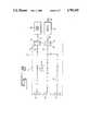
Referring to FIG. 1, there is shown, generally at 10, a connecting and switching module of a type fully disclosed in the above-referenced patent. Acircuit board 12 includes first andsecond connectors third receptacles switching slide 24 is disposed for longitudinal motion in a pair ofparallel guides circuit board 12.
As disclosed in the referenced patent, a plurality of magnetic reed switches (not shown) oncircuit board 12 are influenced by apermanent magnet 30 affixed to move with switchingslide 24. A multiple-conductor trace 32 is connected fromconnector 14 to the magnetic reed switches hidden by switchingslide 24. Similarly, a multiple-conductor trace 34 is connected fromconnector 16 to the magnetic reed switches. Multiple-conductor traces receptacle conductor traces slide 24 into a position whereinpermanent magnet 30 is effective for reversing contacts of the magnetic reed switches. A monitormulti-conductor trace 35, connected line for line to multiple-conductor trace 34 is connected toreceptacle 22.
Since the structure and function of the above elements of connecting and switchingmodule 10 are fully disclosed in the referenced patent, further discussion thereof is omitted from the present application.
Anelectronic circuit 36 is disposed oncircuit board 12 conventionally for driving indicator lamps (not shown) in response to signals on multiple-conductor trace 34. The elements contained inelectronic circuit 36 may differ in relatively minor ways between different communications protocols. For example, signal lines in RS 232C systems are generally single-ended, whereas V.35 and X.21 systems are double-ended. Thus, input resistor connections, and possibly signal voltage levels, may differ between different systems, but a major portion ofelectronic circuit 36 is common to all. Thus, a single basic design ofcircuit board 12, with minor modifications for input resistors and signal levels inelectronic circuit 36 is capable of satisfying substantially all requirements. In this way, longer, more efficient runs of a basic design forcircuit board 12 may be made. Then, minor customization creates the different designs.
Referring now to FIG. 2, a schematic diagram of a typical connecting andswitching module 10 includes multiple-conductor trace 32 connected directly betweenconnector 14 andreceptacle 18 and multiple-conductor trace 34 connected directly betweenconnector 16 andreceptacle 20. Monitor multi-conductor trace 35 branches off multiple-conductor trace 34 for connection of signals thereon to receptacle 22. Alocal equipment 38 which may be, for example, a computer or computer peripheral, is connected by amulti-conductor cable 40 to aconnector 42 mated withconnector 14. Similarly, amodem 44, or other equipment, is connected by amulti-conductor cable 46 to aconnector 48 mated withconnector 16.Modem 44 is connected to other equipment (not shown) by acable 50. An array of magnetic reed switches 52 is connected conductor for conductor between multiple-conductor trace 32 and multiple-conductor trace 34.
In operation, in the absence of a connector of a patch cord (not shown) inserted into either or both ofreceptacles conductor trace 32 and multiple-conductor trace 34, whereby signals atconnector 14 mirror those atconnector 16. Thus,local equipment 38 is connected tomodem 44. Insertion of a connector of a patch cord into eitherreceptacle 18 orreceptacle 20 moves permanent magnet 30 (FIG. 1) into a position opening contacts of array of magnetic reed switches 52, whereby multiple-conductor traces 32 and 34 are disconnected. At the same time, suitable electrical connections are made with the patch cable, whereby a substitute local equipment or modem may be connected for troubleshooting or reassignment of resources.
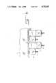
Referring now to FIG. 3, there is shown a rear view of arack 54 containing sixteen connecting and switchingmodules 10 and a power andmonitoring module 55. Each connecting and switchingmodule 10 includes itsconnectors connectors
Power andmonitoring module 55 conventionally includes apower cord 57 as well as afurther connector 59 such as, for example, a DB-25 connector. In addition, the front of power andmonitoring module 55 includes patch receptacles (not shown) corresponding to those previously described. Inserting a patch cord into cavities ofpower monitoring module 55 and one of connecting and switching modules 10' permits monitoring signal activity by viewing the conditions of light-emitting diodes (not shown) on the front of power andmonitoring module 55.
Referring now to FIG. 4, a rear view of arack 56 is shown including sixteen connecting and switching modules 10' and a power andmonitoring module 55'. Power and switchingmodule 55' is identical to a corresponding element previously described.
Each connecting and switching module 10' includes first andsecond connectors connector 58 orconnector 60 and its neighbor, nor vertically between eachconnector 58 and its neighboringconnector 60. As will be detailed below, the close spacing conventionally precludes mounting sixteen connecting and switching modules 10' in a single rack. This constraint leads to the conventional provision of a 12-module rack especially for V.35 modules, rather than the 16-module rack used with most other systems.
The problem is clearly illustrated in FIG. 5 wherein horizontallyadjacent connectors 58 and 58' are illustrated. Aplug 62 is mated toconnector 58 for connection tomulti-conductor cable 40. Using conventional devices, plug 62 extends more than half way into the space betweenconnectors 58 and 58'. The volume required for attachment of plug 62', shown in dashed line, to connector 58' is not available due to encroachment byplug 62. Although not illustrated, the same interference is experienced in the vertical direction between, for example, plug 62 onconnector 58 and a corresponding plug for mating with connector 60 (FIG. 4) directly belowconnector 58.
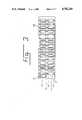
Referring now to FIG. 6, arack 64 is shown having short adapters 66 at every other location along a top row. Along adapter 68 is disposed between each pair of short adapters 66. The difference in length between short adapters 66 andlong adapters 68 permits installation ofadjacent plugs 62 and 62' without mutual interference therebetween. Besides alternating between long and short in the horizontal direction shown, each short adapter 66 in the top row should be adjacent along adapter 68 in the bottom row and vice versa.
Referring now to FIG. 7,long adapter 68 includes ashell 70. A 25-pin connector 72 is connected by acable 74 passing through the interior ofshell 70 to a 34-pin connector 76. When fully assembled, 25-pin connector 72 and 34-pin connector 76 are affixed to ends ofshell 70, using any convenient means, to form a unitary assembly. It will be noted thatindividual conductors 78 are routed as desired to produce the correct interconnections between pins in 25-pin connector 72 and those in 34-pin connector 76. The only difference betweenlong adapter 68 and short adapter 66 is found in the length ofshell 70. The length ofshell 70 required to produce short adapter 66 is illustrated by a dashedline 80.
Besides the RS 232C and large 34-pin connectors, other types of connectors are in common use. For example, fifteen-pin DB-15 connectors are frequently found as a standard in some systems. The present invention is perfectly adaptable to this type of connector using an adapter corresponding to that shown in FIG. 7, wherein 34-pin connector 76 is replaced by the DB-15 connector and the connection pattern ofconductors 78 are made to accommodate the wiring convention for the connector used. The same 25-pin connector 72 is used in such a device, thus avoiding the requirement fordifferent connectors cable 74, identical signal connections can be made oncircuit board 12, regardless the ultimate system with which the module is used. A DB-15 connector, being small, does not require long-short positioning of mating connectors. Thus, a single adapter may be employed, if desired.
Accordingly, the present invention permits each connecting and switchingmodule 10 to be manufactured with identical wiring andconnectors electronic circuit 36 and appropriate selection of long adapters. If standard DB-25 connectors are selected forconnectors
Having described preferred embodiments of the invention with reference to the accompanying drawings, it is to be understood that the invention is not limited to those precise embodiments, and that various changes and modifications may be effected therein by one skilled in the art without departing from the scope or spirit of the invention as defined in the appended claims.
Claims (5)
1. An array of connecting and switching modules, comprising:
at least one connecting and switching module;
at least first and second connectors on said at least one connecting and switching module;
said at least first and second connectors defining a plane;
said at least first and second connectors including a spacing therebetween;
said at least first and second connectors being mateable with first and second plugs, respectively;
said first and second plugs including a lateral dimension such that, when said first plug is mated with said first connector, it intrudes into a space required for mating said second plug with said second connector, whereby simultaneous mating of said first and second plugs with said first and second connectors is prevented;
at least one adapter;
said at least one adapter including first means at a first end thereof for mating with said first connector;
said at least one adapter including second means at a second end thereof for mating with said first plug;
said at least one adapter including a length; and
said length being effective for displacing said first plug with respect to said second plug a sufficient distance to avoid interference between said first and second plugs, whereby simultaneous connection of said first and second plugs with said first and second connectors is enabled.
2. An array according to claim 1 wherein:
said at least one adapter includes at least first and second adapters;
said first means and said second means being disposed on first and second ends of said first adapter;
said second adapter including third means on a first end thereof for mating with said second connector;
said second adapter including fourth means on a second end thereof for mating with said second plug; and
said second adapter having a second length;
said length and said second length having a difference; and
said difference being effective for displacing said first plug with respect to said second plug a sufficient distance to avoid interference between said first and second plugs, whereby simultaneous connection of said first and second plugs is enabled.
3. An array according to claim 1, wherein:
said at least one connecting and switching module includes at least first and second connecting and switching modules;
said first connector being disposed on said first connecting and switching module;
said second connector being disposed on said second connecting and switching module; and
said first and second connectors being adjacent each other.
4. An array according to claim 3, wherein:
said at least first and second connectors includes third and fourth connectors;
said third connector being disposed on said first connecting and switching module;
said fourth connector being disposed on said second connecting and switching module;
said third and fourth connectors being adjacent each other;
said first and third connectors being spaced apart a second distance;
said second and fourth connectors being spaced apart said second distance;
said distance being such that, when said first connector is mated with said first connector, it intrudes into a space required for mating of a third plug on said third connector, whereby simultaneous mating of said first and third plugs with said first and second connectors is prevented;
said first adapter being mated with said first connector; and
said length being effective for displacing said first plug with respect to said second and third plugs a sufficient distance to avoid interference between said first plug and said second plug and between said first plug and said third plug, whereby simultaneous connection of said first, second and third plugs is enabled.
5. An array according to claim 1, wherein said at first and second means include different numbers of pins, and said at least one adapter includes wires therein connecting between pins said first and second means.
Priority Applications (1)
| Application Number | Priority Date | Filing Date | Title |
|---|---|---|---|
| US07/095,915US4782245A (en) | 1987-09-14 | 1987-09-14 | Connecting and switching apparatus with selectable connections |
Applications Claiming Priority (1)
| Application Number | Priority Date | Filing Date | Title |
|---|---|---|---|
| US07/095,915US4782245A (en) | 1987-09-14 | 1987-09-14 | Connecting and switching apparatus with selectable connections |
Publications (1)
| Publication Number | Publication Date |
|---|---|
| US4782245Atrue US4782245A (en) | 1988-11-01 |
Family
ID=22254182
Family Applications (1)
| Application Number | Title | Priority Date | Filing Date |
|---|---|---|---|
| US07/095,915Expired - LifetimeUS4782245A (en) | 1987-09-14 | 1987-09-14 | Connecting and switching apparatus with selectable connections |
Country Status (1)
| Country | Link |
|---|---|
| US (1) | US4782245A (en) |
Cited By (28)
| Publication number | Priority date | Publication date | Assignee | Title |
|---|---|---|---|---|
| US4831634A (en)* | 1988-07-15 | 1989-05-16 | Bull Hn Information Systems Inc. | Modem backplane interconnections |
| US4870863A (en)* | 1987-09-17 | 1989-10-03 | Square D Company | Modular switch device |
| WO1991007833A1 (en)* | 1989-11-16 | 1991-05-30 | Cragun David R | Identifying telephone controller system |
| US5070732A (en)* | 1987-09-17 | 1991-12-10 | Square D Company | Modular sensor device |
| US5199026A (en)* | 1991-02-27 | 1993-03-30 | Memorex Telex N.V. | Token ring wiring concentrator |
| US5553136A (en)* | 1994-05-19 | 1996-09-03 | Tii Industries, Inc. | Modular device for telephone network interface apparatus |
| EP0651920A4 (en)* | 1992-07-24 | 1997-05-14 | Berg Tech Inc | Apparatus for connecting computer devices. |
| US5704797A (en)* | 1994-05-19 | 1998-01-06 | Tii Industries, Inc. | Switchable electrical socket |
| US5724421A (en)* | 1995-11-16 | 1998-03-03 | Antec Corp. | Telephone network interface apparatus |
| US5897399A (en)* | 1997-01-16 | 1999-04-27 | Hewlett-Packard Company | Versatile input/output control and power distribution block for use with automated tooling |
| US6302742B1 (en)* | 2000-06-02 | 2001-10-16 | John Ray Berst | Electrical interface panel |
| US6323873B1 (en) | 1998-01-28 | 2001-11-27 | Gateway, Inc | Computer keyboard display device control |
| US6537109B1 (en) | 1997-01-16 | 2003-03-25 | Hewlett-Packard Company | Chainable I/O termination block system |
| US6570146B1 (en) | 1998-12-23 | 2003-05-27 | Hewlett-Packard Company | Submersible sensor output inverter |
| US6746279B1 (en)* | 2000-11-07 | 2004-06-08 | Ixos Limited | Power distribution system |
| US20060164819A1 (en)* | 2002-12-09 | 2006-07-27 | Siemens Aktiengesellschaft | Circuit board with plug connector |
| US8882536B2 (en) | 2012-01-27 | 2014-11-11 | Chatsworth Products, Inc. | Power distribution unit with interchangeable outlet adapter types |
| US9054449B2 (en) | 2012-01-27 | 2015-06-09 | Chatsworth Products, Inc. | Cable retention system for power distribution unit |
| US9313927B2 (en) | 2010-11-08 | 2016-04-12 | Chatsworth Products, Inc. | Header panel assembly for preventing air circulation above electronic equipment enclosure |
| US9351427B2 (en) | 2013-12-17 | 2016-05-24 | Chatsworth Products, Inc. | Electronic equipment enclosure |
| US9531126B2 (en) | 2014-06-05 | 2016-12-27 | Chatsworth Products, Inc. | Electrical receptacle with locking feature |
| US9585266B2 (en) | 2010-11-08 | 2017-02-28 | Chatsworth Products, Inc. | Header panel assembly for preventing air circulation above electronic equipment enclosure |
| US9655259B2 (en) | 2011-12-09 | 2017-05-16 | Chatsworth Products, Inc. | Data processing equipment structure |
| US20170332842A1 (en)* | 2016-05-20 | 2017-11-23 | Prince Castle LLC | Modular Food Holding System |
| US9844143B2 (en) | 2012-01-27 | 2017-12-12 | Chatsworth Products, Inc. | Board-mounted circuit breakers for electronic equipment enclosures |
| US9955616B2 (en) | 2010-11-08 | 2018-04-24 | Chatsworth Products, Inc. | Header panel assembly for preventing air circulation above electronic equipment enclosure |
| US10547145B2 (en) | 2018-02-05 | 2020-01-28 | Chatworth Products, Inc. | Electric receptacle with locking feature |
| US10595442B2 (en) | 2013-01-11 | 2020-03-17 | Chatsworth Products, Inc. | Data processing equipment structure |
Citations (9)
| Publication number | Priority date | Publication date | Assignee | Title |
|---|---|---|---|---|
| US3842219A (en)* | 1971-02-26 | 1974-10-15 | Thompson J | Method of using gang connector and patching cable assembly |
| US3963301A (en)* | 1974-12-20 | 1976-06-15 | Sperry Rand Corporation | Mother-board interconnection system |
| US4037186A (en)* | 1976-02-09 | 1977-07-19 | Spectron Corporation | Connecting and switching system, and switching apparatus suitable for use therein |
| US4112401A (en)* | 1977-03-14 | 1978-09-05 | Spectron Corporation | Electrical switching apparatus and control system for use therewith |
| US4140918A (en)* | 1973-11-30 | 1979-02-20 | Dynatech Laboratories, Inc. | Electrical jack and patch cord assemblies |
| US4326107A (en)* | 1979-09-24 | 1982-04-20 | Bunker Ramo Corporation | Communication system and means for interconnection of same |
| US4675900A (en)* | 1986-01-09 | 1987-06-23 | Homaco, Inc. | Wire terminal panel for building cable system |
| US4701630A (en)* | 1985-06-27 | 1987-10-20 | International Business Machines Corp. | Local area network station connector |
| US4704599A (en)* | 1984-06-20 | 1987-11-03 | Kimmel Arthur T | Auxiliary power connector and communication channel control circuit |
- 1987
- 1987-09-14USUS07/095,915patent/US4782245A/ennot_activeExpired - Lifetime
Patent Citations (9)
| Publication number | Priority date | Publication date | Assignee | Title |
|---|---|---|---|---|
| US3842219A (en)* | 1971-02-26 | 1974-10-15 | Thompson J | Method of using gang connector and patching cable assembly |
| US4140918A (en)* | 1973-11-30 | 1979-02-20 | Dynatech Laboratories, Inc. | Electrical jack and patch cord assemblies |
| US3963301A (en)* | 1974-12-20 | 1976-06-15 | Sperry Rand Corporation | Mother-board interconnection system |
| US4037186A (en)* | 1976-02-09 | 1977-07-19 | Spectron Corporation | Connecting and switching system, and switching apparatus suitable for use therein |
| US4112401A (en)* | 1977-03-14 | 1978-09-05 | Spectron Corporation | Electrical switching apparatus and control system for use therewith |
| US4326107A (en)* | 1979-09-24 | 1982-04-20 | Bunker Ramo Corporation | Communication system and means for interconnection of same |
| US4704599A (en)* | 1984-06-20 | 1987-11-03 | Kimmel Arthur T | Auxiliary power connector and communication channel control circuit |
| US4701630A (en)* | 1985-06-27 | 1987-10-20 | International Business Machines Corp. | Local area network station connector |
| US4675900A (en)* | 1986-01-09 | 1987-06-23 | Homaco, Inc. | Wire terminal panel for building cable system |
Non-Patent Citations (2)
| Title |
|---|
| Radio Shack, 1985 catalog, pp. 120 121.* |
| Radio Shack, 1985 catalog, pp. 120-121. |
Cited By (58)
| Publication number | Priority date | Publication date | Assignee | Title |
|---|---|---|---|---|
| US4870863A (en)* | 1987-09-17 | 1989-10-03 | Square D Company | Modular switch device |
| US5070732A (en)* | 1987-09-17 | 1991-12-10 | Square D Company | Modular sensor device |
| US4831634A (en)* | 1988-07-15 | 1989-05-16 | Bull Hn Information Systems Inc. | Modem backplane interconnections |
| AU610418B2 (en)* | 1988-07-15 | 1991-05-16 | Bull HN Information Systems Australia Pty. Limited | Modem backplane interconnections |
| WO1991007833A1 (en)* | 1989-11-16 | 1991-05-30 | Cragun David R | Identifying telephone controller system |
| US5127045A (en)* | 1989-11-16 | 1992-06-30 | Cragun David R | Identifying telephone controller system |
| US5199026A (en)* | 1991-02-27 | 1993-03-30 | Memorex Telex N.V. | Token ring wiring concentrator |
| EP0651920A4 (en)* | 1992-07-24 | 1997-05-14 | Berg Tech Inc | Apparatus for connecting computer devices. |
| US5704797A (en)* | 1994-05-19 | 1998-01-06 | Tii Industries, Inc. | Switchable electrical socket |
| US5888085A (en)* | 1994-05-19 | 1999-03-30 | Tii Industries, Inc. | Network interface device with switchable contacts |
| US5553136A (en)* | 1994-05-19 | 1996-09-03 | Tii Industries, Inc. | Modular device for telephone network interface apparatus |
| US5724421A (en)* | 1995-11-16 | 1998-03-03 | Antec Corp. | Telephone network interface apparatus |
| US5897399A (en)* | 1997-01-16 | 1999-04-27 | Hewlett-Packard Company | Versatile input/output control and power distribution block for use with automated tooling |
| US6077125A (en)* | 1997-01-16 | 2000-06-20 | Hewlett-Packard Company | Versatile input/output control and power distribution block for use with automated tooling |
| US6537109B1 (en) | 1997-01-16 | 2003-03-25 | Hewlett-Packard Company | Chainable I/O termination block system |
| US6853367B1 (en) | 1998-01-28 | 2005-02-08 | Gateway, Inc. | Computer keyboard display device control |
| US6323873B1 (en) | 1998-01-28 | 2001-11-27 | Gateway, Inc | Computer keyboard display device control |
| US6570146B1 (en) | 1998-12-23 | 2003-05-27 | Hewlett-Packard Company | Submersible sensor output inverter |
| US6302742B1 (en)* | 2000-06-02 | 2001-10-16 | John Ray Berst | Electrical interface panel |
| US6746279B1 (en)* | 2000-11-07 | 2004-06-08 | Ixos Limited | Power distribution system |
| US20060164819A1 (en)* | 2002-12-09 | 2006-07-27 | Siemens Aktiengesellschaft | Circuit board with plug connector |
| CN100539805C (en)* | 2002-12-09 | 2009-09-09 | 辛特里昂无线电模块有限责任公司 | Printed circuit board with plug connector |
| US12349320B2 (en) | 2010-11-08 | 2025-07-01 | Chatsworth Products, Inc. | Header panel assembly for preventing air circulation above electronic equipment enclosure |
| US11889633B2 (en) | 2010-11-08 | 2024-01-30 | Chatsworth Products, Inc. | Header panel assembly for preventing air circulation above electronic equipment enclosure |
| US9313927B2 (en) | 2010-11-08 | 2016-04-12 | Chatsworth Products, Inc. | Header panel assembly for preventing air circulation above electronic equipment enclosure |
| US11166395B2 (en) | 2010-11-08 | 2021-11-02 | Chatsworth Products, Inc. | Header panel assembly for preventing air circulation above electronic equipment enclosure |
| US10932400B2 (en) | 2010-11-08 | 2021-02-23 | Chatsworth Products, Inc. | Header panel assembly for preventing air circulation above electronic equipment enclosure |
| US10568246B2 (en) | 2010-11-08 | 2020-02-18 | Chatsworth Products, Inc. | Header panel assembly for preventing air circulation above electronic equipment enclosure |
| US9585266B2 (en) | 2010-11-08 | 2017-02-28 | Chatsworth Products, Inc. | Header panel assembly for preventing air circulation above electronic equipment enclosure |
| US9955616B2 (en) | 2010-11-08 | 2018-04-24 | Chatsworth Products, Inc. | Header panel assembly for preventing air circulation above electronic equipment enclosure |
| US10306812B2 (en) | 2010-11-08 | 2019-05-28 | Chatsworth Products, Inc. | Header panel assembly for preventing air circulation above electronic equipment enclosure |
| US9655259B2 (en) | 2011-12-09 | 2017-05-16 | Chatsworth Products, Inc. | Data processing equipment structure |
| US10709039B2 (en) | 2011-12-09 | 2020-07-07 | Chatsworth Products, Inc. | Data processing equipment structure |
| US10374360B2 (en) | 2012-01-27 | 2019-08-06 | Chatsworth Products, Inc. | Cable retention system for power distribution unit |
| US10187995B2 (en) | 2012-01-27 | 2019-01-22 | Chatsworth Products, Inc. | Board-mounted circuit breakers for electronic equipment enclosures |
| US8882536B2 (en) | 2012-01-27 | 2014-11-11 | Chatsworth Products, Inc. | Power distribution unit with interchangeable outlet adapter types |
| US10349524B2 (en) | 2012-01-27 | 2019-07-09 | Chatsworth Products, Inc. | Board-mounted circuit breakers for electronic equipment enclosures |
| US9054449B2 (en) | 2012-01-27 | 2015-06-09 | Chatsworth Products, Inc. | Cable retention system for power distribution unit |
| US9509086B2 (en) | 2012-01-27 | 2016-11-29 | Chatsworth Products, Inc. | Cable retention system for power distribution unit |
| US10594082B2 (en) | 2012-01-27 | 2020-03-17 | Chatsworth Products, Inc. | Cable retention system for power distribution unit |
| US10797441B2 (en) | 2012-01-27 | 2020-10-06 | Chatsworth Products, Inc. | Cable retention system for power distribution unit |
| US9844143B2 (en) | 2012-01-27 | 2017-12-12 | Chatsworth Products, Inc. | Board-mounted circuit breakers for electronic equipment enclosures |
| US11647610B2 (en) | 2013-01-11 | 2023-05-09 | Chatsworth Products, Inc. | Modular thermal isolation barrier for data processing equipment structure |
| US12063758B2 (en) | 2013-01-11 | 2024-08-13 | Chatsworth Products, Inc. | Modular thermal isolation barrier for data processing equipment structure |
| US10595442B2 (en) | 2013-01-11 | 2020-03-17 | Chatsworth Products, Inc. | Data processing equipment structure |
| US9949406B2 (en) | 2013-12-17 | 2018-04-17 | Chatsworth Products, Inc. | Electronic equipment enclosure |
| US11985799B2 (en) | 2013-12-17 | 2024-05-14 | Chatsworth Products, Inc. | Electronic equipment enclosure |
| US10674634B2 (en) | 2013-12-17 | 2020-06-02 | Chatsworth Products, Inc. | Electronic equipment enclosure |
| US11083108B2 (en) | 2013-12-17 | 2021-08-03 | Chatsworth Products, Inc. | Electronic equipment enclosure |
| US9351427B2 (en) | 2013-12-17 | 2016-05-24 | Chatsworth Products, Inc. | Electronic equipment enclosure |
| US10356951B2 (en) | 2013-12-17 | 2019-07-16 | Chatsworth Products, Inc. | Electronic equipment enclosure |
| US9531126B2 (en) | 2014-06-05 | 2016-12-27 | Chatsworth Products, Inc. | Electrical receptacle with locking feature |
| US11185191B2 (en)* | 2016-05-20 | 2021-11-30 | Marmon Foodservice Technologies, Inc. | Modular food holding system |
| US20170332842A1 (en)* | 2016-05-20 | 2017-11-23 | Prince Castle LLC | Modular Food Holding System |
| US11322891B2 (en) | 2018-02-05 | 2022-05-03 | Chatsworth Products, Inc. | Electrical receptacle with locking feature |
| US10855030B2 (en) | 2018-02-05 | 2020-12-01 | Chatsworth Products, Inc. | Electrical receptacle with locking feature |
| US11909143B2 (en) | 2018-02-05 | 2024-02-20 | Chatsworth Products, Inc. | Electrical receptacle with locking feature |
| US10547145B2 (en) | 2018-02-05 | 2020-01-28 | Chatworth Products, Inc. | Electric receptacle with locking feature |
Similar Documents
| Publication | Publication Date | Title |
|---|---|---|
| US4782245A (en) | Connecting and switching apparatus with selectable connections | |
| US5108294A (en) | Terminator connector | |
| US6347963B1 (en) | Interchangeable backplane interface connection panel | |
| US5030123A (en) | Connector and patch panel for digital video and data | |
| US6244908B1 (en) | Switch within a data connector jack | |
| EP1559277B1 (en) | Network connection sensing module | |
| US6394853B1 (en) | Data connector for selective switching between at least two distinct mating connector plugs | |
| US4242721A (en) | Electrical connector assembly for interconnecting remote signal stations to central signal processing systems | |
| AU584522B2 (en) | Connector assembly | |
| US4179172A (en) | Modular hardware packaging apparatus | |
| US4548453A (en) | Right angle coaxial plug connector | |
| US5076801A (en) | Electronic component including insulation displacement interconnect means | |
| US6431906B1 (en) | Modular connectors with detachable line status indicators | |
| WO2003010858A1 (en) | Jack ; jack assembly ; and methods | |
| WO2004039091A2 (en) | High density patching system | |
| US4717344A (en) | Connector for circuit boards | |
| US4878847A (en) | Patchfield system | |
| EP1037314B1 (en) | Receptacle and printed circuit assembly for receiving a plug | |
| US5790660A (en) | Shunted modular jack | |
| US7044803B2 (en) | High density patching system with longframe jacks | |
| EP0643449B1 (en) | Cable connector for a ribbon cable | |
| KR20000022614A (en) | Selective termination connector assembly | |
| US4542372A (en) | Data distribution apparatus | |
| US6722899B2 (en) | Connective apparatus in which a number of contacts are grouped into a plurality of contact groups according to intended use | |
| JP2007505593A (en) | Network connection detection assembly |
Legal Events
| Date | Code | Title | Description |
|---|---|---|---|
| STCF | Information on status: patent grant | Free format text:PATENTED CASE | |
| AS | Assignment | Owner name:NORTHERN TELECOM LIMITED, CANADA Free format text:ASSIGNMENT OF ASSIGNORS INTEREST.;ASSIGNOR:HENRY, MARK B.;REEL/FRAME:005450/0927 Effective date:19900703 | |
| FPAY | Fee payment | Year of fee payment:4 | |
| FPAY | Fee payment | Year of fee payment:8 | |
| FPAY | Fee payment | Year of fee payment:12 | |
| AS | Assignment | Owner name:NORTEL NETWORKS CORPORATION, CANADA Free format text:CHANGE OF NAME;ASSIGNOR:NORTHERN TELECOM LIMITED;REEL/FRAME:010567/0001 Effective date:19990429 | |
| AS | Assignment | Owner name:NORTEL NETWORKS LIMITED, CANADA Free format text:CHANGE OF NAME;ASSIGNOR:NORTEL NETWORKS CORPORATION;REEL/FRAME:011195/0706 Effective date:20000830 Owner name:NORTEL NETWORKS LIMITED,CANADA Free format text:CHANGE OF NAME;ASSIGNOR:NORTEL NETWORKS CORPORATION;REEL/FRAME:011195/0706 Effective date:20000830 |