US4782239A - Optical position measuring apparatus - Google Patents
Optical position measuring apparatusDownload PDFInfo
- Publication number
- US4782239A US4782239AUS06/846,950US84695086AUS4782239AUS 4782239 AUS4782239 AUS 4782239AUS 84695086 AUS84695086 AUS 84695086AUS 4782239 AUS4782239 AUS 4782239A
- Authority
- US
- United States
- Prior art keywords
- radiation
- optical system
- receiving surface
- optical axis
- detecting
- Prior art date
- Legal status (The legal status is an assumption and is not a legal conclusion. Google has not performed a legal analysis and makes no representation as to the accuracy of the status listed.)
- Expired - Fee Related
Links
Images


Classifications
- G—PHYSICS
- G01—MEASURING; TESTING
- G01S—RADIO DIRECTION-FINDING; RADIO NAVIGATION; DETERMINING DISTANCE OR VELOCITY BY USE OF RADIO WAVES; LOCATING OR PRESENCE-DETECTING BY USE OF THE REFLECTION OR RERADIATION OF RADIO WAVES; ANALOGOUS ARRANGEMENTS USING OTHER WAVES
- G01S7/00—Details of systems according to groups G01S13/00, G01S15/00, G01S17/00
- G01S7/48—Details of systems according to groups G01S13/00, G01S15/00, G01S17/00 of systems according to group G01S17/00
- G01S7/481—Constructional features, e.g. arrangements of optical elements
- G01S7/4811—Constructional features, e.g. arrangements of optical elements common to transmitter and receiver
- G—PHYSICS
- G01—MEASURING; TESTING
- G01S—RADIO DIRECTION-FINDING; RADIO NAVIGATION; DETERMINING DISTANCE OR VELOCITY BY USE OF RADIO WAVES; LOCATING OR PRESENCE-DETECTING BY USE OF THE REFLECTION OR RERADIATION OF RADIO WAVES; ANALOGOUS ARRANGEMENTS USING OTHER WAVES
- G01S17/00—Systems using the reflection or reradiation of electromagnetic waves other than radio waves, e.g. lidar systems
- G01S17/02—Systems using the reflection of electromagnetic waves other than radio waves
- G01S17/06—Systems determining position data of a target
- G01S17/46—Indirect determination of position data
Definitions
- the present inventionrelates to an optical position measuring apparatus of the type in which the position or displacement of an object is measured by projecting a radiation beam on the object and detecting the position of the reflected beam spot from the object surface.
- the apparatusgenerally comprises a light projection optical system for projecting a radiation beam onto an object, a light-receiving optical system for receiving the reflected beam from the object, and a one-dimensional optical sensor.
- the light-receiving optical systemis disposed obliquely to the projection optical axis and functions to form a spot image of the reflected beam on the sensor. The position of the formed image is detected to obtain the necessary information with respect to the measured object.
- the change of the position of the spot image on the one-dimensional sensoris detected to measure the displacement of the object in the direction along the projection optical axis.
- the above-shown position measuring apparatus using radiation beam such as laser beamis a kind of non-contact measuring apparatus which has many advantages over the conventional contact type position measuring apparatus. First of all, even for such an object made of very soft plastics, measurement can be made without any danger of the object being damaged Secondly, it is very easy to use and especially useful as a distance detector for automation equipments and devices such as a factory work robot.
- the prior art apparatusmeasures the distance to an object on the principle of triangulation.
- a laser light source 1emits a laser beam toward the object the position of which varies in the range of from +a to -a in the direction of the projection optical axis A.
- the laser beamis projected on the object through a projection optical system 2.
- the reflected light of the beam spot from the objectenters a light-receiving optical system 3.
- the incident angle of the reflected light to the optical system 3varies depending on the position of the object.
- the change of the incident angleis detected as the change of the position of the beam spot on a linear (one-dimensional) optical sensor 4 disposed perpendicularly to the optical axis B of the light-receiving optical system 3.
- the projection optical axisA of the projection optical system 2is oblique to the optical axis B of the light-receiving optical system 3 and the light-receiving surface of the sensor 4 is normal to the optical axis B.
- This means that the beam on the object and the image of the beam (+a' ⁇ -a') on the light-receiving surfaceare not in conjugated relation to each other.
- the image of the beam spot formedis blurred.
- This prior art measuring apparatusmeasures the distance by electrically detecting the center of the beam. Consequently, the range of measurement allowable for the apparatus is limited to the range within which the blurred image can be processed electrically.
- PSDposition sensitive device
- the depth of focus on the object sidewill be rendered so small that only a very small measurable range may be obtained even when electrical processing is carried out well.
- the light-receiving optical system 3it is necessary to use the light-receiving optical system 3 as a minifying optical system. In this case, however, it is impossible to improve the accuracy of measurement.
- the position sensitive devicegenerally has a structure comprising an n-type substrate and a p-type substrate uniformly laid on the n-type substrate.
- a pair of electrodes for reading out signalsare provided at both ends of the p-type substrate and a reference electrode is provided at the n-type substrate.
- the electric current flowing through the pair of electrodesvaries depending upon the position of the spot light on the surface of the p-type substrate.
- a further problemis caused by the fact that the optical axis B of the light-receiving optical system 3 is oblique to the projection optical axis A. Due to this fact, the magnification rate of the distance between two points on the sensor 4 (for example, the distance from the center 0' to +a' or to -a') corresponding to the distance between arbitrary two points on the optical axis A (for example, the distance from the center 0 to +a or -a) is not constant but variable. To compensate for this a correction is needed. Furthermore, the sensitivity for detection varies according to the position of the measured point (the magnification rate gradually decreases and the sensitivity gradually lowers in the direction in which the measured point is more distant from the light-receiving optical system 3).
- the second prior art apparatus shown in FIG.is an optical position measuring apparatus which has been proposed to overcome one of the above-mentioned problems, that is, the problem of the blurred image formed on the light-receiving surface of the sensor 4.
- the principal plane PP of the light-receiving optical system 3, the light-receiving surface of the sensor 4 and the optical axis A of the projection optical system 2are so disposed as to intersect each other at a point P.
- the point (+a ⁇ -a) on the projection optical axis A and the image (+a' ⁇ -a') on the light-receiving surfaceare in conjugated relation to each other. Consequently, there is no problem of the blurred image.
- this prior art apparatusinvolves again the problem that the magnification rate is variable according to the position of the measured point. Also, the accuracy of measurement attainable by the apparatus is still unsatisfactory.
- an object of the present inventionis to provide an optical position measuring apparatus which has a broader measurement range and a higher accuracy of measurement than the prior art.
- one embodiment of apparatus of the invention for measuring the distance to an objectcomprises projection means for projecting a radiation beam onto the object, the projection means including radiation generating means and a first optical system for projecting the radiation beam on the surface of the object; and detection means for detecting the radiation beam reflected from the object, the detection means including radiation detecting means having a radiation-receiving surface for detecting the intensity distribution of the radiation on the radiation-receiving surface, and a second optical system for guiding at least a portion of the reflected radiation beam from the object to the radiation-receiving surface, and for bringing the radiation-receiving surface into a substantially optically conjugated relation with a portion of the optical axis of the first optical system and also into a predetermined relationship wherein the position of the radiation beam on the radiation-receiving surface changes in proportion to an amount of displacement of the object on the optical axis of the first optical system.
- FIGS. 1 and 2show the optical position measuring apparatus according to the prior art
- FIG. 3shows a first embodiment of the invention
- FIG. 4shows a second embodiment of the invention
- FIG. 5shows a part of a modification of the second embodiment
- FIG. 6shows a third embodiment of the invention
- FIG. 7is a view illustrating the principle of the third embodiment
- FIG. 8shows a part of a modification of the third embodiment
- FIG. 9shows another modification of the third embodiment
- FIG. 10is a sectional view taken along the line V--V in FIG. 9;
- FIG. 11shows a further modification of the third embodiment
- FIG. 12is a sectional view taken along the line VIII--VIII in FIG. 11;
- FIG. 13shows still a further modification of the third embodiment
- FIG. 14shows a part of a fourth embodiment of the invention.
- a light source 11which may be, for example, a semiconductor laser, emits a beam of light.
- a projection lens 12Through a projection lens 12, the circular or slit-like beam is projected onto the surface of an object to be measured.
- the object surface (+a ⁇ -a)lies in the measurable range of the apparatus along a line segment the projection axis A which is coincident with the optical axis of the projection lens 12.
- a light-receiving lens 13is so disposed that its optical axis B intersects the projection optical axis B at right angles. Through the light-receiving lens 13, an image of the beam projected on the object surface (+a ⁇ -a) is formed on an image plane 14' so long as the object lies within the range of measurement.
- the image plane 14'is disposed parallel to the projection optical axis.
- the exit beam from the light-receiving lens 13is deflected toward a one-dimensional optical sensor 14 by a reflecting mirror 15.
- the light-receiving surface of the sensor 14is conjugated with the object surface (+a ⁇ -a), like the image plane 14'. Therefore, the light-receiving surface of the sensor 14 and the object surface (+a ⁇ -a) on the optical axis A are in conjugated relation each other relative to the light-receiving lens 13.
- the linear optical sensor 14is also parallel to the projection optical axis A.
- the output signal from the sensor 14is processed in an operation circuit 16 to measure the position or displacement of the object in the direction along the projection optical axis A.
- a beam of light emitted from the light source 11is projected on the object surface (+a ⁇ -a) lying within the measurable range through the lens 12 and reflected by the object surface, and a portion of the reflected light is obliquely incident upon the lens 13. Then, the light beam is deflected toward the light-receiving surface (+a" ⁇ -a") of the one-dimensional sensor 14 and forms a beam spot image thereon.
- the position of the beam spot imagechanges by a value corresponding to the amount of displacement of the object surface (+a ⁇ -a) multiplied by the magnification of the lens 13, i.e., the position of the beam spot image changes linearly in accordance with the amount of displacement of the object surface along a line segment of the optical axis.
- the position of the beam spot imagecan be detected. More specifically, the amount of displacement of the object surface is measured from the existing difference between the first and second position signals through the operation circuit 16.
- the reflecting mirror 15is not indispensable for the apparatus according to the invention.
- the reflecting mirror 15can be omitted.
- the linear sensor 14is arranged on the image plane 14' conjugate with the object surface (+a ⁇ -a) lying within the range of measurement.
- the use of the reflecting mirror 15enables the linear sensor 14 to be located on the side of the projection lens 12 thereby realizing a compact construction of the apparatus as a whole.
- the light source 11is not limited to a laser only, but it may be any source of radiation which generates a spot beam of radiation such as visible light rays, ultraviolet rays or infra-red rays.
- FIG. 4shows a second embodiment of the invention in which a single lens is used as a light-receiving lens and also as a projection lens.
- the light-receiving lens 13receives a beam of light projected on and reflected by an object surface (+a ⁇ -a) lying off of the optical axis B. In this case, only the large field angle area of the lens 13 is used. The near-axis area thereof is not used.
- the second embodiment shown in FIG. 4is based on the concept that the unused near-axis area of the light-receiving lens can be used for projecting a beam of light onto the object surface (+a ⁇ -a).
- the reference numeral 13'denotes the light-projection and receiving lens and 11 denotes again a light source.
- the light source 11is located on the optical axis of the light-projection and receiving lens 13'.
- the beam emitted from the light source 11goes straight along the optical axis C of the lens 13' and then the beam is deflected at right angles.
- the projection light beamis reflected by the object surface (+a ⁇ -a).
- a portion of the reflected lightobliquely passes through the dual-purpose lens 13' as an off axis beam and then it is directed to a one-dimensional optical sensor 14 by a reflection mirror 15. On the light-receiving surface of the sensor 14, the beam forms a beam spot image.
- the linear sensor 14must be disposed conjugately with the object surface (+a ⁇ -a) lying on the projection optical axis A within the measurement range.
- the arrangement of this second embodimenthas advantages over the first embodiment. First of all, since the lens 13' serves as a projection lens and also as a light-receiving lens, a substantial cost reduction can be achieved.
- the space occupied by the projection lens 12 in the first embodimentcan be used for another purpose. In case of the shown second embodiment, this space is used for receiving the sensor 14 with the reflection mirror 15 being inclined relative to the projection axis A. This enables a realization of a more compact construction of the apparatus as a whole.
- magnification system lenswhen a magnification system lens is used while passing a light beam through the same in the opposite direction, the lens must be used as a magnification system lens. By doing so, it is possible to hold the same conjugate relation under the given condition of aberrations.
- the beam from the light source 11passes through the dual-purpose lens 13' from right to left on the plane of the drawing whereas the reflected light from the object passes through the lens in the opposite direction, that is, from left to right.
- the dual-purpose lensis so designed that for both of the light beams coming from opposite directions the image magnification rate (ratio of distance on object side to distance on image side) can be enlarged.
- the conjugate relation(relationship of distance from lens) between the object (+a ⁇ -a on the projection axis A) and the image (+a" ⁇ -a" on the sensor 14) and the conjugate relation between the light source 11 on the object side and the light beam on the image side (+a ⁇ -a on the projection axis A) are entirely different from each other regarding the dual-purpose lens 13'.
- FIG. 5shows a modification of the second embodiment made to overcome the above-mentioned difficulty in designing the dual-purpose lens 13'.
- a subsidiary lens 18is interposed between the dual-purpose lens 13' and the light source 11.
- Other parts (not shown) of the modified embodimentcorrespond to those of the above second embodiment and, therefore, need not be further described.
- the subsidiary lens 18must be so positioned between the lens 13' and the light source 11 as not to cut off the beam of light coming from the object surface.
- a composite projection systemis provided which is composed of the subsidiary lens 18 and the dual-purpose lens 13' and has a composite focal length different from the focal length of the light-receiving system which is composed of the dual-purpose lens 13' only.
- the lens designercan select the brightness of the projection system independently of the light-receiving system as desired by suitably selecting the focal length of the subsidiary lens 18. It is also possible to broaden the measurable range by increasing the effective length of the linear sensor 14 because the measurable range on the projection optical axis A corresponds to the effective length of the linear sensor.
- the constructions of the above first and second embodimentshave been determined on the premise that the object to be measured has a flat surface extending substantially perpendicularly to the projection optical axis A so that the projected light beam from the projection lens 2 can be scattered by the object surface uniformly in every direction to some extent.
- the object to be measuredhas a flat surface extending substantially perpendicularly to the projection optical axis A so that the projected light beam from the projection lens 2 can be scattered by the object surface uniformly in every direction to some extent.
- the direction in which the beam is mainly scatteredis variable depending on the inclination of the object surface. Therefore, in the most unfavourable case, the light-receiving lens 13 receives no scattered light from the object surface and the sensor 14 can not detect the position of the beam.
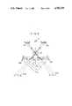
- the light beam emitted from the light source 11goes along the projection optical axis which is coincident with the optical axis of the lens 13'. Then, the beam impinges upon the object surface and forms a beam of light at the intersection of the object surface and the optical axis X. A portion of the reflected light (scattered light) from the light beam is deflected toward the projection axis X by a first reflecting member 16. The reflected light is further deflected toward the dual-purpose lens 13' by a second reflecting member 17 provided in the vicinity of projection axis X. After passing through the lens 13', the light forms a light spot image on a linear sensor 14 the light-receiving surface of which is normal to the optical axis (projection axis X) of the lens 13'.
- the first projection (projection image) P 1 of the linear sensor 14which is conjugate with the effective light-receiving range (+b ⁇ -b) of the sensor 14 relative to the dual-purpose lens 13, is normal to the projection optical axis X. Therefore, by suitably selecting the positions, angles and distances of the first and second reflecting members 16 and 17, one can rotate the first projection P 1 by 90° up to a position corresponding to the projection optical axis X. Accordingly, it is possible to establish a conjugated relation between the object point on the projection axis X (+a ⁇ -a) corresponding to the object point of the first projection P 1 (+a 1 ⁇ -a 1 ) and the image point on the linear sensor 14 (+b ⁇ -b).
- the first projection P 1is deflected at first in the opposite direction to the projection optical axis X by the second reflecting member 17. Thereby the first projection P 1 turns to a second projection P 2 which is line-symmetric to P 1 . Then, the second projection P 2 is deflected toward the projection optical axis X by the first reflecting member 16.
- the first reflecting memberis provided at a position on the bisector BS of the angle ⁇ which the optical axis X and the second projection P 2 form. Therefore, the second projection P 2 is turned to a position corresponding to the object point on the optical axis X (+a ⁇ -a).
- the dual-purpose lens 13' in FIG. 7is formed axis-symmetrically about the projection optical axis X. Therefore, two or more sets of the reflecting optical system comprising the first and second reflecting members 16 and 17 can be arranged in two or more directions so as to receive the scattered light in any direction through the reflecting optical systems.
- the third embodiment shown in FIG. 6has been made on the basis of the image formation principle described above.
- One of the reflecting optical systemscomprises a first reflecting member 16A and a second reflecting member 17A.
- the other onecomprises a first reflecting member 16B and a second reflecting member 17B.
- the first reflecting members 16A and 16Bare symmetrically arranged on the right side and on the left side of the projection optical axis X corresponding to the optical axis of the dual-purpose lens 13'.
- the second reflecting members 17A and 17Bare symmetrically arranged relative to the optical axis X but at positions nearer to the optical axis X than the first reflecting members.
- the reflected light (scattered light) from the object surfaceis reflected at first toward the optical axis X by the first reflecting members 16A and 16B and then deflected toward the dual-purpose lens 13' by the second reflecting members 17A and 17B.
- the light beams deflected by the second reflecting members 17A and 17Bpass through the wide field angle area (marginal area) of the dual-purpose lens 13' and form their spot images on two linear sensors 14A and 14B arranged symmetrically on a plane normal to the optical axis of the lens 13'.
- the output signals from the linear sensors 14A and 14Bare processed in an operation circuit as previously described.
- the positions, angles and distances of the two sets of the reflecting optical systems (16A, 17A and 16B, 17B)are suitably selected so as to establish a conjugate relation between the photo detection range (+b ⁇ -b) of the sensors 14A, 14B and the measurement range (+a ⁇ -a) on the optical axis X with respect to the dual-purpose lens 13'.
- the reliability of the optical measuring apparatusis improved.
- the third embodimentis able to receive a sufficient quantity of the reflected light to detect the position of the beam spot by the other sensor.
- the scattering characteristic of the beam spot on the object surfaceis flat and the beam is reflected uniformly in all directions, the output signal will be obtained from both of the two linear sensors 14A and 14B symmetrically arranged. In this case, therefore, the accuracy of measurement can be improved further by adding a processing circuit such as that for equalization.
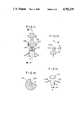
- FIG. 8shows an modification of the third embodiment shown in FIG. 6. This modification is constructed by adding two more reflecting optical systems and two more linear sensors to the third embodiment.
- four sets of reflecting optical systems 16A, 17A; 16C, 17C; 16B, 17B and 16D, 17Dare symmetrically arranged at 90° angular intervals about the optical axis of the dual-purpose lens 13'.
- four linear sensors 14B, 14D, 14A and 14Care arranged about the optical axis of the dual-purpose lens 13' (projection optical axis).
- the scattered light from the object surfacecan be received in four directions by four reflecting optical systems 16A ⁇ 16D, 17A ⁇ 17D and four linear sensors 14A ⁇ 14D. Even for such a case where the object to be measured has a slant surface and the scattered light from the object surface exhibits a characteristic of high directivity, the apparatus according to the modification does not fail to receive the reflected light from the object surface.
- FIGS. 9 and 10show another modification of the third embodiment.
- the first reflecting memberis constituted of a ring-like cone mirror 16' which has a mirror surface inside.
- the second reflecting memberis constituted of a ring-like cone mirror 17' which has a mirror surface outside and a central opening 17a'.
- linear sensors 14A ⁇ 14Dare arranged about the optical axis of the dual-purpose lens 13'.
- a beam of the projected lightpasses through the central opening 17a' of hhe second reflecting member 17'.
- the apparatus of this modificationis able to measure the position of the object surface without fail.
- the reliability of this apparatuscan be improved further by increasing the number of linear sensors 14A ⁇ 14D arranged about the optical axis of the dual-purpose lens 13'.
- This modificationhas an additional advantage that the cone mirrors 16' and 17' used as the first and second reflecting members can be prepared in a very simple and inexpensive manner by press forming of a metal plate.
- the cone mirrors made of metal plateare easy to process and can be supported by simple holders. Therefore, a substantial reduction of the total manufacturing cost may be achieved by this modification.
- a subsidiary lens 18 as shown in FIG. 5may be used also in the third embodiment.
- the interposition of such a subsidiary lens between the light source 11 and the dual-purpose lens 13' in the third embodimentwill bring about the same valuable effect as previously described by reference to FIG. 5.
- FIGS. 11 and 12A further modification of the third embodiment is shown in FIGS. 11 and 12.
- a rectangular prism 20is provided directly above the dual-purpose lens 13' on the optical axis of the latter.
- a beam of light emitted from the light source 11is deflected downwardly as viewed on the plane of the drawing by the rectangular prism 20.
- the deflected beamtravels along the optical axis of the lens 13' and passes through the central area of the lens. After passing through the lens 13', the beam impinges upon an object surface lying on the projection optical axis X.
- a pair of third reflecting members 19A and 19Bare provided on the left side and right side of the rectangular prism 20 as seen best in FIG. 11. The reflecting surfaces of the third reflecting members are disposed parallel with the optical axis of the lens 13'.
- the oblique beams reflected by the second reflecting members 17A and 17B and then transmitted through the lens 13'are inwardly reflected by the third reflecting members 19A and 19B and form beam images on a one-dimensional sensor 14E disposed above the rectangular prism 20.
- the positions of two beam imagescan be detected from a single sensor, one image from the left-hand side area and the other image from the right-hand side area of the sensor at the same time.
- the pair of third reflecting members 19A and 19Bmust be spaced from each other so sufficiently that the left side beam image (-b ⁇ +b) and the right side beam image (+b ⁇ -b) never overlap each other.
- the one-dimensional sensor 14Ea one-dimensional CCD image sensor or the like should be used as the one-dimensional sensor 14E.
- the third reflecting members 19A and 19Bmay be replaced by a cylindrical mirror with its mirror surface inside.
- the one-dimensional image sensoris required to have a suitably large size (at least two times larger than the detectable range +b ⁇ -b). Since two beam images are formed on the sensor at the same time in this modification, the type of sensor useful as the sensor 14E is limited to some extent.
- a PSD type sensorwhich produces a position signal corresponding to the position of the weight center of the light intensity is unsuitable for this modification.
- the optical system of the modification shown in FIGS. 11 and 12corresponds to that of the third embodiment shown in FIG. 6.
- FIG. 13shows still a further modification of the third embodiment in which the sensor 14E which is preferably a CCD image sensor is replaced by a PSD type of sensor.
- a rotary shutter 22 driven by a motor 21is provided between the above-described prism 20 and a PSD.
- the PSDis on the optical axis of the dual purpose lens 13'.
- the third reflecting members 19A and 19B as described abovereflect beams toward the PSD. The two beams running toward the PSD are alternately shut off by the rotary shutter 22.
- the rotary shutter 22has an opening 22A formed by cutting out a portion of the shutter plate.
- the rotary shuttertherefore, serves as a chopper which shuts out the beam toward the PSD until the opening 22A comes in the area of the passage of the beam.
- the distance between the third reflecting members 19A and 19Bcan be selected in such manner that two beam images overlap each other on an area of the PSD near the center 0 of its light-receiving surface (+b ⁇ -b).
- the one-dimensional sensorby a PSD capable of two-dimensional measurement and to arrange four sets of reflecting optical systems (each comprising first, second and third reflecting members as shown above) in four directions regularly about the dual-purpose lens 13' (cf. FIG. 8).
- four beam imageswill be formed on the PSD at the same time.
- the measuring apparatusalmost never fails to measure the position of the object surface however strong the directivity of the scattered light may be, irrespective of which direction is the direction of the directivity of the scattered light from the object surface.
- FIG. 14A fourth embodiment of the invention is schematically shown in FIG. 14.
- the above-shown dual-purpose lens 13'is used as a light-receiving lens only.
- a lens 23 and a light-source 11are arranged between the lens 13' and an object.
Landscapes
- Engineering & Computer Science (AREA)
- Physics & Mathematics (AREA)
- Computer Networks & Wireless Communication (AREA)
- General Physics & Mathematics (AREA)
- Radar, Positioning & Navigation (AREA)
- Remote Sensing (AREA)
- Electromagnetism (AREA)
- Measurement Of Optical Distance (AREA)
- Length Measuring Devices By Optical Means (AREA)
Abstract
Description
Claims (8)
Applications Claiming Priority (4)
| Application Number | Priority Date | Filing Date | Title |
|---|---|---|---|
| JP7231285AJPS61231409A (en) | 1985-04-05 | 1985-04-05 | Optical position measuring apparatus |
| JP60-72312 | 1985-04-05 | ||
| JP7231185AJPS61231408A (en) | 1985-04-05 | 1985-04-05 | Optical non-contact position measuring device |
| JP60-72311 | 1985-04-05 |
Publications (1)
| Publication Number | Publication Date |
|---|---|
| US4782239Atrue US4782239A (en) | 1988-11-01 |
Family
ID=26413452
Family Applications (1)
| Application Number | Title | Priority Date | Filing Date |
|---|---|---|---|
| US06/846,950Expired - Fee RelatedUS4782239A (en) | 1985-04-05 | 1986-04-01 | Optical position measuring apparatus |
Country Status (1)
| Country | Link |
|---|---|
| US (1) | US4782239A (en) |
Cited By (103)
| Publication number | Priority date | Publication date | Assignee | Title |
|---|---|---|---|---|
| US4851657A (en)* | 1985-12-23 | 1989-07-25 | Minolta Camera Kabushiki Kaisha | Focus condition detecting device using weighted center or contrast evaluation |
| US5113082A (en)* | 1990-09-11 | 1992-05-12 | Moshe Golberstein | Electro-optical instrument with self-contained photometer |
| US5144833A (en)* | 1990-09-27 | 1992-09-08 | International Business Machines Corporation | Atomic force microscopy |
| DE4130119A1 (en)* | 1991-09-11 | 1993-03-25 | Leuze Electronic Gmbh & Co | Optical triangulation distance measurement device - light source, transmission lens, wide angle receiver lens and position sensitive light receiver |
| US5198877A (en)* | 1990-10-15 | 1993-03-30 | Pixsys, Inc. | Method and apparatus for three-dimensional non-contact shape sensing |
| US5202867A (en)* | 1987-01-29 | 1993-04-13 | Canon Kabushiki Kaisha | Condensing optical system with corrected chromatic aberration, and information recording/reproducing apparatus using this optical system |
| EP0464849A3 (en)* | 1990-07-06 | 1993-06-16 | Omron Corporation | Displacement sensor and positioner |
| US5229619A (en)* | 1990-12-27 | 1993-07-20 | U.S. Philips Corporation | Apparatus for optically measuring the height of surface irregularities having an imaged scanning spot formed on a radiation diffusive screen |
| US5383454A (en)* | 1990-10-19 | 1995-01-24 | St. Louis University | System for indicating the position of a surgical probe within a head on an image of the head |
| US5512760A (en)* | 1993-05-06 | 1996-04-30 | U.S. Philips Corporation | Optical height detector with coaxial irradiation and image axes and plural detectors spaced along the image axis |
| US5748767A (en)* | 1988-02-01 | 1998-05-05 | Faro Technology, Inc. | Computer-aided surgery apparatus |
| US5760905A (en)* | 1995-10-13 | 1998-06-02 | Kabushiki Kaisha Topcon | Distance measuring apparatus |
| US5800352A (en)* | 1994-09-15 | 1998-09-01 | Visualization Technology, Inc. | Registration system for use with position tracking and imaging system for use in medical applications |
| US5829444A (en)* | 1994-09-15 | 1998-11-03 | Visualization Technology, Inc. | Position tracking and imaging system for use in medical applications |
| US5871445A (en)* | 1993-04-26 | 1999-02-16 | St. Louis University | System for indicating the position of a surgical probe within a head on an image of the head |
| US5969822A (en)* | 1994-09-28 | 1999-10-19 | Applied Research Associates Nz Ltd. | Arbitrary-geometry laser surface scanner |
| US5987349A (en)* | 1990-10-19 | 1999-11-16 | Image Guided Technologies, Inc. | Method for determining the position and orientation of two moveable objects in three-dimensional space |
| US6146390A (en)* | 1992-04-21 | 2000-11-14 | Sofamor Danek Holdings, Inc. | Apparatus and method for photogrammetric surgical localization |
| US6167295A (en)* | 1991-01-28 | 2000-12-26 | Radionics, Inc. | Optical and computer graphic stereotactic localizer |
| US6167145A (en)* | 1996-03-29 | 2000-12-26 | Surgical Navigation Technologies, Inc. | Bone navigation system |
| US6226548B1 (en) | 1997-09-24 | 2001-05-01 | Surgical Navigation Technologies, Inc. | Percutaneous registration apparatus and method for use in computer-assisted surgical navigation |
| US6236875B1 (en) | 1994-10-07 | 2001-05-22 | Surgical Navigation Technologies | Surgical navigation systems including reference and localization frames |
| US6275725B1 (en) | 1991-01-28 | 2001-08-14 | Radionics, Inc. | Stereotactic optical navigation |
| US6296613B1 (en) | 1997-08-22 | 2001-10-02 | Synthes (U.S.A.) | 3D ultrasound recording device |
| US6347240B1 (en) | 1990-10-19 | 2002-02-12 | St. Louis University | System and method for use in displaying images of a body part |
| US6358260B1 (en) | 1998-04-20 | 2002-03-19 | Med-Logics, Inc. | Automatic corneal shaper with two separate drive mechanisms |
| US6425905B1 (en) | 2000-11-29 | 2002-07-30 | Med-Logics, Inc. | Method and apparatus for facilitating removal of a corneal graft |
| US6428508B1 (en) | 2000-02-01 | 2002-08-06 | Enlighten Technologies, Inc. | Pulsed vacuum cataract removal system |
| US6585651B2 (en) | 1999-04-20 | 2003-07-01 | Synthes Ag Chur | Method and device for percutaneous determination of points associated with the surface of an organ |
| US6663644B1 (en) | 2000-06-02 | 2003-12-16 | Med-Logics, Inc. | Cutting blade assembly for a microkeratome |
| US6694168B2 (en) | 1998-06-22 | 2004-02-17 | Synthes (U.S.A.) | Fiducial matching using fiducial implants |
| US6699285B2 (en) | 1999-09-24 | 2004-03-02 | Scieran Technologies, Inc. | Eye endoplant for the reattachment of a retina |
| US6702832B2 (en) | 1999-07-08 | 2004-03-09 | Med Logics, Inc. | Medical device for cutting a cornea that has a vacuum ring with a slitted vacuum opening |
| US6725082B2 (en) | 1999-03-17 | 2004-04-20 | Synthes U.S.A. | System and method for ligament graft placement |
| US20040122311A1 (en)* | 1991-01-28 | 2004-06-24 | Cosman Eric R. | Surgical positioning system |
| US6978166B2 (en) | 1994-10-07 | 2005-12-20 | Saint Louis University | System for use in displaying images of a body part |
| US7217276B2 (en) | 1999-04-20 | 2007-05-15 | Surgical Navigational Technologies, Inc. | Instrument guidance method and system for image guided surgery |
| US20070125162A1 (en)* | 2005-06-15 | 2007-06-07 | Ghazi Babak R | Wireless liquid-level measuring free pour spout |
| US7277594B2 (en) | 1999-05-03 | 2007-10-02 | Ao Technology Ag | System and method for preparing an image corrected for the presence of a gravity induced distortion |
| US7313430B2 (en) | 2003-08-28 | 2007-12-25 | Medtronic Navigation, Inc. | Method and apparatus for performing stereotactic surgery |
| US7311700B2 (en) | 2000-11-29 | 2007-12-25 | Med-Logics, Inc. | LASIK laminar flow system |
| US7366562B2 (en) | 2003-10-17 | 2008-04-29 | Medtronic Navigation, Inc. | Method and apparatus for surgical navigation |
| US7542791B2 (en) | 2003-01-30 | 2009-06-02 | Medtronic Navigation, Inc. | Method and apparatus for preplanning a surgical procedure |
| US7567834B2 (en) | 2004-05-03 | 2009-07-28 | Medtronic Navigation, Inc. | Method and apparatus for implantation between two vertebral bodies |
| US7570791B2 (en) | 2003-04-25 | 2009-08-04 | Medtronic Navigation, Inc. | Method and apparatus for performing 2D to 3D registration |
| US7599730B2 (en) | 2002-11-19 | 2009-10-06 | Medtronic Navigation, Inc. | Navigation system for cardiac therapies |
| US7606613B2 (en) | 1999-03-23 | 2009-10-20 | Medtronic Navigation, Inc. | Navigational guidance via computer-assisted fluoroscopic imaging |
| US7630753B2 (en) | 2002-02-28 | 2009-12-08 | Medtronic Navigation, Inc. | Method and apparatus for perspective inversion |
| US7636595B2 (en) | 2004-10-28 | 2009-12-22 | Medtronic Navigation, Inc. | Method and apparatus for calibrating non-linear instruments |
| US7657300B2 (en) | 1999-10-28 | 2010-02-02 | Medtronic Navigation, Inc. | Registration of human anatomy integrated for electromagnetic localization |
| US7660623B2 (en) | 2003-01-30 | 2010-02-09 | Medtronic Navigation, Inc. | Six degree of freedom alignment display for medical procedures |
| US7697972B2 (en) | 2002-11-19 | 2010-04-13 | Medtronic Navigation, Inc. | Navigation system for cardiac therapies |
| US7763035B2 (en) | 1997-12-12 | 2010-07-27 | Medtronic Navigation, Inc. | Image guided spinal surgery guide, system and method for use thereof |
| US7797032B2 (en) | 1999-10-28 | 2010-09-14 | Medtronic Navigation, Inc. | Method and system for navigating a catheter probe in the presence of field-influencing objects |
| US7831082B2 (en) | 2000-06-14 | 2010-11-09 | Medtronic Navigation, Inc. | System and method for image based sensor calibration |
| US7835778B2 (en) | 2003-10-16 | 2010-11-16 | Medtronic Navigation, Inc. | Method and apparatus for surgical navigation of a multiple piece construct for implantation |
| US7835784B2 (en) | 2005-09-21 | 2010-11-16 | Medtronic Navigation, Inc. | Method and apparatus for positioning a reference frame |
| US7840253B2 (en) | 2003-10-17 | 2010-11-23 | Medtronic Navigation, Inc. | Method and apparatus for surgical navigation |
| US7853305B2 (en) | 2000-04-07 | 2010-12-14 | Medtronic Navigation, Inc. | Trajectory storage apparatus and method for surgical navigation systems |
| US7881770B2 (en) | 2000-03-01 | 2011-02-01 | Medtronic Navigation, Inc. | Multiple cannula image guided tool for image guided procedures |
| US7998062B2 (en) | 2004-03-29 | 2011-08-16 | Superdimension, Ltd. | Endoscope structures and techniques for navigating to a target in branched structure |
| US8057407B2 (en) | 1999-10-28 | 2011-11-15 | Medtronic Navigation, Inc. | Surgical sensor |
| US8074662B2 (en) | 1999-10-28 | 2011-12-13 | Medtronic Navigation, Inc. | Surgical communication and power system |
| US8112292B2 (en) | 2006-04-21 | 2012-02-07 | Medtronic Navigation, Inc. | Method and apparatus for optimizing a therapy |
| US8165658B2 (en) | 2008-09-26 | 2012-04-24 | Medtronic, Inc. | Method and apparatus for positioning a guide relative to a base |
| USRE43328E1 (en) | 1997-11-20 | 2012-04-24 | Medtronic Navigation, Inc | Image guided awl/tap/screwdriver |
| US8175681B2 (en) | 2008-12-16 | 2012-05-08 | Medtronic Navigation Inc. | Combination of electromagnetic and electropotential localization |
| US8200314B2 (en) | 1992-08-14 | 2012-06-12 | British Telecommunications Public Limited Company | Surgical navigation |
| US8239001B2 (en) | 2003-10-17 | 2012-08-07 | Medtronic Navigation, Inc. | Method and apparatus for surgical navigation |
| USRE43952E1 (en) | 1989-10-05 | 2013-01-29 | Medtronic Navigation, Inc. | Interactive system for local intervention inside a non-homogeneous structure |
| US8452068B2 (en) | 2008-06-06 | 2013-05-28 | Covidien Lp | Hybrid registration method |
| US8473032B2 (en) | 2008-06-03 | 2013-06-25 | Superdimension, Ltd. | Feature-based registration method |
| US8494613B2 (en) | 2009-08-31 | 2013-07-23 | Medtronic, Inc. | Combination localization system |
| US8494614B2 (en) | 2009-08-31 | 2013-07-23 | Regents Of The University Of Minnesota | Combination localization system |
| US8611984B2 (en) | 2009-04-08 | 2013-12-17 | Covidien Lp | Locatable catheter |
| US8644907B2 (en) | 1999-10-28 | 2014-02-04 | Medtronic Navigaton, Inc. | Method and apparatus for surgical navigation |
| US8660635B2 (en) | 2006-09-29 | 2014-02-25 | Medtronic, Inc. | Method and apparatus for optimizing a computer assisted surgical procedure |
| US8663088B2 (en) | 2003-09-15 | 2014-03-04 | Covidien Lp | System of accessories for use with bronchoscopes |
| US8768437B2 (en) | 1998-08-20 | 2014-07-01 | Sofamor Danek Holdings, Inc. | Fluoroscopic image guided surgery system with intraoperative registration |
| US8764725B2 (en) | 2004-02-09 | 2014-07-01 | Covidien Lp | Directional anchoring mechanism, method and applications thereof |
| US8838199B2 (en) | 2002-04-04 | 2014-09-16 | Medtronic Navigation, Inc. | Method and apparatus for virtual digital subtraction angiography |
| US8905920B2 (en) | 2007-09-27 | 2014-12-09 | Covidien Lp | Bronchoscope adapter and method |
| US8932207B2 (en) | 2008-07-10 | 2015-01-13 | Covidien Lp | Integrated multi-functional endoscopic tool |
| US9055881B2 (en) | 2004-04-26 | 2015-06-16 | Super Dimension Ltd. | System and method for image-based alignment of an endoscope |
| US9168102B2 (en) | 2006-01-18 | 2015-10-27 | Medtronic Navigation, Inc. | Method and apparatus for providing a container to a sterile environment |
| US9575140B2 (en) | 2008-04-03 | 2017-02-21 | Covidien Lp | Magnetic interference detection system and method |
| US9675424B2 (en) | 2001-06-04 | 2017-06-13 | Surgical Navigation Technologies, Inc. | Method for calibrating a navigation system |
| US10418705B2 (en) | 2016-10-28 | 2019-09-17 | Covidien Lp | Electromagnetic navigation antenna assembly and electromagnetic navigation system including the same |
| US10426555B2 (en) | 2015-06-03 | 2019-10-01 | Covidien Lp | Medical instrument with sensor for use in a system and method for electromagnetic navigation |
| US10446931B2 (en) | 2016-10-28 | 2019-10-15 | Covidien Lp | Electromagnetic navigation antenna assembly and electromagnetic navigation system including the same |
| US10478254B2 (en) | 2016-05-16 | 2019-11-19 | Covidien Lp | System and method to access lung tissue |
| US10517505B2 (en) | 2016-10-28 | 2019-12-31 | Covidien Lp | Systems, methods, and computer-readable media for optimizing an electromagnetic navigation system |
| US10582834B2 (en) | 2010-06-15 | 2020-03-10 | Covidien Lp | Locatable expandable working channel and method |
| US10615500B2 (en) | 2016-10-28 | 2020-04-07 | Covidien Lp | System and method for designing electromagnetic navigation antenna assemblies |
| US10638952B2 (en) | 2016-10-28 | 2020-05-05 | Covidien Lp | Methods, systems, and computer-readable media for calibrating an electromagnetic navigation system |
| US10722311B2 (en) | 2016-10-28 | 2020-07-28 | Covidien Lp | System and method for identifying a location and/or an orientation of an electromagnetic sensor based on a map |
| US10751126B2 (en) | 2016-10-28 | 2020-08-25 | Covidien Lp | System and method for generating a map for electromagnetic navigation |
| US10792106B2 (en) | 2016-10-28 | 2020-10-06 | Covidien Lp | System for calibrating an electromagnetic navigation system |
| US10952593B2 (en) | 2014-06-10 | 2021-03-23 | Covidien Lp | Bronchoscope adapter |
| US11006914B2 (en) | 2015-10-28 | 2021-05-18 | Medtronic Navigation, Inc. | Apparatus and method for maintaining image quality while minimizing x-ray dosage of a patient |
| US11219489B2 (en) | 2017-10-31 | 2022-01-11 | Covidien Lp | Devices and systems for providing sensors in parallel with medical tools |
| US11331150B2 (en) | 1999-10-28 | 2022-05-17 | Medtronic Navigation, Inc. | Method and apparatus for surgical navigation |
| US12089902B2 (en) | 2019-07-30 | 2024-09-17 | Coviden Lp | Cone beam and 3D fluoroscope lung navigation |
Citations (5)
| Publication number | Priority date | Publication date | Assignee | Title |
|---|---|---|---|---|
| US3864030A (en)* | 1972-07-11 | 1975-02-04 | Acuity Syst | Eye position measuring technique |
| US4274735A (en)* | 1978-05-25 | 1981-06-23 | Canon Kabushiki Kaisha | Distance measuring device |
| US4445029A (en)* | 1980-06-16 | 1984-04-24 | Seiko Koki Kabushiki Kaisha | Distance detector using a photopotentiometer and a continuous detecting system |
| US4595271A (en)* | 1983-11-05 | 1986-06-17 | Canon Kabushiki Kaisha | In-focus state detection device |
| US4595829A (en)* | 1982-05-25 | 1986-06-17 | Ernst Leitz Wetzlar Gmbh | Apparatus for automatically focusing objects to be viewed in optical instruments |
- 1986
- 1986-04-01USUS06/846,950patent/US4782239A/ennot_activeExpired - Fee Related
Patent Citations (5)
| Publication number | Priority date | Publication date | Assignee | Title |
|---|---|---|---|---|
| US3864030A (en)* | 1972-07-11 | 1975-02-04 | Acuity Syst | Eye position measuring technique |
| US4274735A (en)* | 1978-05-25 | 1981-06-23 | Canon Kabushiki Kaisha | Distance measuring device |
| US4445029A (en)* | 1980-06-16 | 1984-04-24 | Seiko Koki Kabushiki Kaisha | Distance detector using a photopotentiometer and a continuous detecting system |
| US4595829A (en)* | 1982-05-25 | 1986-06-17 | Ernst Leitz Wetzlar Gmbh | Apparatus for automatically focusing objects to be viewed in optical instruments |
| US4595271A (en)* | 1983-11-05 | 1986-06-17 | Canon Kabushiki Kaisha | In-focus state detection device |
Cited By (203)
| Publication number | Priority date | Publication date | Assignee | Title |
|---|---|---|---|---|
| US4851657A (en)* | 1985-12-23 | 1989-07-25 | Minolta Camera Kabushiki Kaisha | Focus condition detecting device using weighted center or contrast evaluation |
| US5202867A (en)* | 1987-01-29 | 1993-04-13 | Canon Kabushiki Kaisha | Condensing optical system with corrected chromatic aberration, and information recording/reproducing apparatus using this optical system |
| US5748767A (en)* | 1988-02-01 | 1998-05-05 | Faro Technology, Inc. | Computer-aided surgery apparatus |
| USRE43952E1 (en) | 1989-10-05 | 2013-01-29 | Medtronic Navigation, Inc. | Interactive system for local intervention inside a non-homogeneous structure |
| EP0464849A3 (en)* | 1990-07-06 | 1993-06-16 | Omron Corporation | Displacement sensor and positioner |
| US5113082A (en)* | 1990-09-11 | 1992-05-12 | Moshe Golberstein | Electro-optical instrument with self-contained photometer |
| US5144833A (en)* | 1990-09-27 | 1992-09-08 | International Business Machines Corporation | Atomic force microscopy |
| USRE37299E1 (en)* | 1990-09-27 | 2001-07-31 | International Business Machines Corporation | Atomic force microscopy |
| US5198877A (en)* | 1990-10-15 | 1993-03-30 | Pixsys, Inc. | Method and apparatus for three-dimensional non-contact shape sensing |
| USRE35816E (en)* | 1990-10-15 | 1998-06-02 | Image Guided Technologies Inc. | Method and apparatus for three-dimensional non-contact shape sensing |
| US6374135B1 (en) | 1990-10-19 | 2002-04-16 | Saint Louis University | System for indicating the position of a surgical probe within a head on an image of the head |
| US6490467B1 (en) | 1990-10-19 | 2002-12-03 | Surgical Navigation Technologies, Inc. | Surgical navigation systems including reference and localization frames |
| US5383454A (en)* | 1990-10-19 | 1995-01-24 | St. Louis University | System for indicating the position of a surgical probe within a head on an image of the head |
| US6678545B2 (en) | 1990-10-19 | 2004-01-13 | Saint Louis University | System for determining the position in a scan image corresponding to the position of an imaging probe |
| US6434415B1 (en) | 1990-10-19 | 2002-08-13 | St. Louis University | System for use in displaying images of a body part |
| US5851183A (en)* | 1990-10-19 | 1998-12-22 | St. Louis University | System for indicating the position of a surgical probe within a head on an image of the head |
| US20060241400A1 (en)* | 1990-10-19 | 2006-10-26 | St. Louis University | Method of determining the position of an instrument relative to a body of a patient |
| US7072704B2 (en) | 1990-10-19 | 2006-07-04 | St. Louis University | System for indicating the position of a surgical probe within a head on an image of the head |
| US5891034A (en)* | 1990-10-19 | 1999-04-06 | St. Louis University | System for indicating the position of a surgical probe within a head on an image of the head |
| US6347240B1 (en) | 1990-10-19 | 2002-02-12 | St. Louis University | System and method for use in displaying images of a body part |
| US6463319B1 (en) | 1990-10-19 | 2002-10-08 | St. Louis University | System for indicating the position of a surgical probe within a head on an image of the head |
| US5987349A (en)* | 1990-10-19 | 1999-11-16 | Image Guided Technologies, Inc. | Method for determining the position and orientation of two moveable objects in three-dimensional space |
| US6076008A (en)* | 1990-10-19 | 2000-06-13 | St. Louis University | System for indicating the position of a surgical probe within a head on an image of the head |
| US5229619A (en)* | 1990-12-27 | 1993-07-20 | U.S. Philips Corporation | Apparatus for optically measuring the height of surface irregularities having an imaged scanning spot formed on a radiation diffusive screen |
| US6167295A (en)* | 1991-01-28 | 2000-12-26 | Radionics, Inc. | Optical and computer graphic stereotactic localizer |
| US6275725B1 (en) | 1991-01-28 | 2001-08-14 | Radionics, Inc. | Stereotactic optical navigation |
| US20040122311A1 (en)* | 1991-01-28 | 2004-06-24 | Cosman Eric R. | Surgical positioning system |
| DE4130119A1 (en)* | 1991-09-11 | 1993-03-25 | Leuze Electronic Gmbh & Co | Optical triangulation distance measurement device - light source, transmission lens, wide angle receiver lens and position sensitive light receiver |
| US6491702B2 (en) | 1992-04-21 | 2002-12-10 | Sofamor Danek Holdings, Inc. | Apparatus and method for photogrammetric surgical localization |
| US6165181A (en)* | 1992-04-21 | 2000-12-26 | Sofamor Danek Holdings, Inc. | Apparatus and method for photogrammetric surgical localization |
| US6146390A (en)* | 1992-04-21 | 2000-11-14 | Sofamor Danek Holdings, Inc. | Apparatus and method for photogrammetric surgical localization |
| US8200314B2 (en) | 1992-08-14 | 2012-06-12 | British Telecommunications Public Limited Company | Surgical navigation |
| US6442416B1 (en) | 1993-04-22 | 2002-08-27 | Image Guided Technologies, Inc. | Determination of the position and orientation of at least one object in space |
| US7139601B2 (en) | 1993-04-26 | 2006-11-21 | Surgical Navigation Technologies, Inc. | Surgical navigation systems including reference and localization frames |
| US5871445A (en)* | 1993-04-26 | 1999-02-16 | St. Louis University | System for indicating the position of a surgical probe within a head on an image of the head |
| US5512760A (en)* | 1993-05-06 | 1996-04-30 | U.S. Philips Corporation | Optical height detector with coaxial irradiation and image axes and plural detectors spaced along the image axis |
| US6934575B2 (en) | 1994-09-15 | 2005-08-23 | Ge Medical Systems Global Technology Company, Llc | Position tracking and imaging system for use in medical applications |
| US6694167B1 (en) | 1994-09-15 | 2004-02-17 | Ge Medical Systems Global Technology Company, Llc | System for monitoring a position of a medical instrument with respect to a patient's head |
| US6341231B1 (en) | 1994-09-15 | 2002-01-22 | Visualization Technology, Inc. | Position tracking and imaging system for use in medical applications |
| US8473026B2 (en) | 1994-09-15 | 2013-06-25 | Ge Medical Systems Global Technology Company | System for monitoring a position of a medical instrument with respect to a patient's body |
| US6175756B1 (en) | 1994-09-15 | 2001-01-16 | Visualization Technology Inc. | Position tracking and imaging system for use in medical applications |
| US6445943B1 (en) | 1994-09-15 | 2002-09-03 | Visualization Technology, Inc. | Position tracking and imaging system for use in medical applications |
| US5967980A (en)* | 1994-09-15 | 1999-10-19 | Visualization Technology, Inc. | Position tracking and imaging system for use in medical applications |
| US5873822A (en)* | 1994-09-15 | 1999-02-23 | Visualization Technology, Inc. | Automatic registration system for use with position tracking and imaging system for use in medical applications |
| US5829444A (en)* | 1994-09-15 | 1998-11-03 | Visualization Technology, Inc. | Position tracking and imaging system for use in medical applications |
| US6738656B1 (en) | 1994-09-15 | 2004-05-18 | Ge Medical Systems Global Technology Company, Llc | Automatic registration system for use with position tracking an imaging system for use in medical applications |
| US5800352A (en)* | 1994-09-15 | 1998-09-01 | Visualization Technology, Inc. | Registration system for use with position tracking and imaging system for use in medical applications |
| US6687531B1 (en) | 1994-09-15 | 2004-02-03 | Ge Medical Systems Global Technology Company, Llc | Position tracking and imaging system for use in medical applications |
| US5969822A (en)* | 1994-09-28 | 1999-10-19 | Applied Research Associates Nz Ltd. | Arbitrary-geometry laser surface scanner |
| US6978166B2 (en) | 1994-10-07 | 2005-12-20 | Saint Louis University | System for use in displaying images of a body part |
| US8046053B2 (en) | 1994-10-07 | 2011-10-25 | Foley Kevin T | System and method for modifying images of a body part |
| US6236875B1 (en) | 1994-10-07 | 2001-05-22 | Surgical Navigation Technologies | Surgical navigation systems including reference and localization frames |
| US5760905A (en)* | 1995-10-13 | 1998-06-02 | Kabushiki Kaisha Topcon | Distance measuring apparatus |
| US6167145A (en)* | 1996-03-29 | 2000-12-26 | Surgical Navigation Technologies, Inc. | Bone navigation system |
| US6296613B1 (en) | 1997-08-22 | 2001-10-02 | Synthes (U.S.A.) | 3D ultrasound recording device |
| USRE42194E1 (en) | 1997-09-24 | 2011-03-01 | Medtronic Navigation, Inc. | Percutaneous registration apparatus and method for use in computer-assisted surgical navigation |
| USRE42226E1 (en) | 1997-09-24 | 2011-03-15 | Medtronic Navigation, Inc. | Percutaneous registration apparatus and method for use in computer-assisted surgical navigation |
| USRE45509E1 (en) | 1997-09-24 | 2015-05-05 | Medtronic Navigation, Inc. | Percutaneous registration apparatus and method for use in computer-assisted surgical navigation |
| USRE44305E1 (en) | 1997-09-24 | 2013-06-18 | Medtronic Navigation, Inc. | Percutaneous registration apparatus and method for use in computer-assisted surgical navigation |
| USRE39133E1 (en) | 1997-09-24 | 2006-06-13 | Surgical Navigation Technologies, Inc. | Percutaneous registration apparatus and method for use in computer-assisted surgical navigation |
| US6226548B1 (en) | 1997-09-24 | 2001-05-01 | Surgical Navigation Technologies, Inc. | Percutaneous registration apparatus and method for use in computer-assisted surgical navigation |
| USRE46409E1 (en) | 1997-11-20 | 2017-05-23 | Medtronic Navigation, Inc. | Image guided awl/tap/screwdriver |
| USRE46422E1 (en) | 1997-11-20 | 2017-06-06 | Medtronic Navigation, Inc. | Image guided awl/tap/screwdriver |
| USRE43328E1 (en) | 1997-11-20 | 2012-04-24 | Medtronic Navigation, Inc | Image guided awl/tap/screwdriver |
| US8105339B2 (en) | 1997-12-12 | 2012-01-31 | Sofamor Danek Holdings, Inc. | Image guided spinal surgery guide system and method for use thereof |
| US7763035B2 (en) | 1997-12-12 | 2010-07-27 | Medtronic Navigation, Inc. | Image guided spinal surgery guide, system and method for use thereof |
| US6358260B1 (en) | 1998-04-20 | 2002-03-19 | Med-Logics, Inc. | Automatic corneal shaper with two separate drive mechanisms |
| US6694168B2 (en) | 1998-06-22 | 2004-02-17 | Synthes (U.S.A.) | Fiducial matching using fiducial implants |
| US8768437B2 (en) | 1998-08-20 | 2014-07-01 | Sofamor Danek Holdings, Inc. | Fluoroscopic image guided surgery system with intraoperative registration |
| US6725082B2 (en) | 1999-03-17 | 2004-04-20 | Synthes U.S.A. | System and method for ligament graft placement |
| US7606613B2 (en) | 1999-03-23 | 2009-10-20 | Medtronic Navigation, Inc. | Navigational guidance via computer-assisted fluoroscopic imaging |
| US7996064B2 (en) | 1999-03-23 | 2011-08-09 | Medtronic Navigation, Inc. | System and method for placing and determining an appropriately sized surgical implant |
| US7217276B2 (en) | 1999-04-20 | 2007-05-15 | Surgical Navigational Technologies, Inc. | Instrument guidance method and system for image guided surgery |
| US8845655B2 (en) | 1999-04-20 | 2014-09-30 | Medtronic Navigation, Inc. | Instrument guide system |
| US6585651B2 (en) | 1999-04-20 | 2003-07-01 | Synthes Ag Chur | Method and device for percutaneous determination of points associated with the surface of an organ |
| US7277594B2 (en) | 1999-05-03 | 2007-10-02 | Ao Technology Ag | System and method for preparing an image corrected for the presence of a gravity induced distortion |
| US6702832B2 (en) | 1999-07-08 | 2004-03-09 | Med Logics, Inc. | Medical device for cutting a cornea that has a vacuum ring with a slitted vacuum opening |
| US6699285B2 (en) | 1999-09-24 | 2004-03-02 | Scieran Technologies, Inc. | Eye endoplant for the reattachment of a retina |
| US8074662B2 (en) | 1999-10-28 | 2011-12-13 | Medtronic Navigation, Inc. | Surgical communication and power system |
| US8644907B2 (en) | 1999-10-28 | 2014-02-04 | Medtronic Navigaton, Inc. | Method and apparatus for surgical navigation |
| US8290572B2 (en) | 1999-10-28 | 2012-10-16 | Medtronic Navigation, Inc. | Method and system for navigating a catheter probe in the presence of field-influencing objects |
| US7797032B2 (en) | 1999-10-28 | 2010-09-14 | Medtronic Navigation, Inc. | Method and system for navigating a catheter probe in the presence of field-influencing objects |
| US8057407B2 (en) | 1999-10-28 | 2011-11-15 | Medtronic Navigation, Inc. | Surgical sensor |
| US11331150B2 (en) | 1999-10-28 | 2022-05-17 | Medtronic Navigation, Inc. | Method and apparatus for surgical navigation |
| US9504530B2 (en) | 1999-10-28 | 2016-11-29 | Medtronic Navigation, Inc. | Method and apparatus for surgical navigation |
| US8548565B2 (en) | 1999-10-28 | 2013-10-01 | Medtronic Navigation, Inc. | Registration of human anatomy integrated for electromagnetic localization |
| US7657300B2 (en) | 1999-10-28 | 2010-02-02 | Medtronic Navigation, Inc. | Registration of human anatomy integrated for electromagnetic localization |
| US6428508B1 (en) | 2000-02-01 | 2002-08-06 | Enlighten Technologies, Inc. | Pulsed vacuum cataract removal system |
| US10898153B2 (en) | 2000-03-01 | 2021-01-26 | Medtronic Navigation, Inc. | Multiple cannula image guided tool for image guided procedures |
| US7881770B2 (en) | 2000-03-01 | 2011-02-01 | Medtronic Navigation, Inc. | Multiple cannula image guided tool for image guided procedures |
| US7853305B2 (en) | 2000-04-07 | 2010-12-14 | Medtronic Navigation, Inc. | Trajectory storage apparatus and method for surgical navigation systems |
| US8634897B2 (en) | 2000-04-07 | 2014-01-21 | Medtronic Navigation, Inc. | Trajectory storage apparatus and method for surgical navigation systems |
| US6663644B1 (en) | 2000-06-02 | 2003-12-16 | Med-Logics, Inc. | Cutting blade assembly for a microkeratome |
| US7831082B2 (en) | 2000-06-14 | 2010-11-09 | Medtronic Navigation, Inc. | System and method for image based sensor calibration |
| US8320653B2 (en) | 2000-06-14 | 2012-11-27 | Medtronic Navigation, Inc. | System and method for image based sensor calibration |
| US7311700B2 (en) | 2000-11-29 | 2007-12-25 | Med-Logics, Inc. | LASIK laminar flow system |
| US6425905B1 (en) | 2000-11-29 | 2002-07-30 | Med-Logics, Inc. | Method and apparatus for facilitating removal of a corneal graft |
| US9675424B2 (en) | 2001-06-04 | 2017-06-13 | Surgical Navigation Technologies, Inc. | Method for calibrating a navigation system |
| US9757087B2 (en) | 2002-02-28 | 2017-09-12 | Medtronic Navigation, Inc. | Method and apparatus for perspective inversion |
| US7630753B2 (en) | 2002-02-28 | 2009-12-08 | Medtronic Navigation, Inc. | Method and apparatus for perspective inversion |
| US8838199B2 (en) | 2002-04-04 | 2014-09-16 | Medtronic Navigation, Inc. | Method and apparatus for virtual digital subtraction angiography |
| US9642514B2 (en) | 2002-04-17 | 2017-05-09 | Covidien Lp | Endoscope structures and techniques for navigating to a target in a branched structure |
| US10743748B2 (en) | 2002-04-17 | 2020-08-18 | Covidien Lp | Endoscope structures and techniques for navigating to a target in branched structure |
| US8696685B2 (en) | 2002-04-17 | 2014-04-15 | Covidien Lp | Endoscope structures and techniques for navigating to a target in branched structure |
| US8696548B2 (en) | 2002-04-17 | 2014-04-15 | Covidien Lp | Endoscope structures and techniques for navigating to a target in branched structure |
| US7599730B2 (en) | 2002-11-19 | 2009-10-06 | Medtronic Navigation, Inc. | Navigation system for cardiac therapies |
| US8060185B2 (en) | 2002-11-19 | 2011-11-15 | Medtronic Navigation, Inc. | Navigation system for cardiac therapies |
| US8046052B2 (en) | 2002-11-19 | 2011-10-25 | Medtronic Navigation, Inc. | Navigation system for cardiac therapies |
| US8467853B2 (en) | 2002-11-19 | 2013-06-18 | Medtronic Navigation, Inc. | Navigation system for cardiac therapies |
| US8401616B2 (en) | 2002-11-19 | 2013-03-19 | Medtronic Navigation, Inc. | Navigation system for cardiac therapies |
| US7697972B2 (en) | 2002-11-19 | 2010-04-13 | Medtronic Navigation, Inc. | Navigation system for cardiac therapies |
| US7974677B2 (en) | 2003-01-30 | 2011-07-05 | Medtronic Navigation, Inc. | Method and apparatus for preplanning a surgical procedure |
| US11707363B2 (en) | 2003-01-30 | 2023-07-25 | Medtronic Navigation, Inc. | Method and apparatus for post-operative tuning of a spinal implant |
| US7660623B2 (en) | 2003-01-30 | 2010-02-09 | Medtronic Navigation, Inc. | Six degree of freedom alignment display for medical procedures |
| US7542791B2 (en) | 2003-01-30 | 2009-06-02 | Medtronic Navigation, Inc. | Method and apparatus for preplanning a surgical procedure |
| US9867721B2 (en) | 2003-01-30 | 2018-01-16 | Medtronic Navigation, Inc. | Method and apparatus for post-operative tuning of a spinal implant |
| US11684491B2 (en) | 2003-01-30 | 2023-06-27 | Medtronic Navigation, Inc. | Method and apparatus for post-operative tuning of a spinal implant |
| US7570791B2 (en) | 2003-04-25 | 2009-08-04 | Medtronic Navigation, Inc. | Method and apparatus for performing 2D to 3D registration |
| US7313430B2 (en) | 2003-08-28 | 2007-12-25 | Medtronic Navigation, Inc. | Method and apparatus for performing stereotactic surgery |
| US7925328B2 (en) | 2003-08-28 | 2011-04-12 | Medtronic Navigation, Inc. | Method and apparatus for performing stereotactic surgery |
| US10383509B2 (en) | 2003-09-15 | 2019-08-20 | Covidien Lp | System of accessories for use with bronchoscopes |
| US9089261B2 (en) | 2003-09-15 | 2015-07-28 | Covidien Lp | System of accessories for use with bronchoscopes |
| US8663088B2 (en) | 2003-09-15 | 2014-03-04 | Covidien Lp | System of accessories for use with bronchoscopes |
| US7835778B2 (en) | 2003-10-16 | 2010-11-16 | Medtronic Navigation, Inc. | Method and apparatus for surgical navigation of a multiple piece construct for implantation |
| US8706185B2 (en) | 2003-10-16 | 2014-04-22 | Medtronic Navigation, Inc. | Method and apparatus for surgical navigation of a multiple piece construct for implantation |
| US8359730B2 (en) | 2003-10-17 | 2013-01-29 | Medtronic Navigation, Inc. | Method of forming an electromagnetic sensing coil in a medical instrument |
| US8549732B2 (en) | 2003-10-17 | 2013-10-08 | Medtronic Navigation, Inc. | Method of forming an electromagnetic sensing coil in a medical instrument |
| US8239001B2 (en) | 2003-10-17 | 2012-08-07 | Medtronic Navigation, Inc. | Method and apparatus for surgical navigation |
| US8271069B2 (en) | 2003-10-17 | 2012-09-18 | Medtronic Navigation, Inc. | Method and apparatus for surgical navigation |
| US7751865B2 (en) | 2003-10-17 | 2010-07-06 | Medtronic Navigation, Inc. | Method and apparatus for surgical navigation |
| US7840253B2 (en) | 2003-10-17 | 2010-11-23 | Medtronic Navigation, Inc. | Method and apparatus for surgical navigation |
| US7366562B2 (en) | 2003-10-17 | 2008-04-29 | Medtronic Navigation, Inc. | Method and apparatus for surgical navigation |
| US7971341B2 (en) | 2003-10-17 | 2011-07-05 | Medtronic Navigation, Inc. | Method of forming an electromagnetic sensing coil in a medical instrument for a surgical navigation system |
| US7818044B2 (en) | 2003-10-17 | 2010-10-19 | Medtronic Navigation, Inc. | Method and apparatus for surgical navigation |
| US8764725B2 (en) | 2004-02-09 | 2014-07-01 | Covidien Lp | Directional anchoring mechanism, method and applications thereof |
| US7998062B2 (en) | 2004-03-29 | 2011-08-16 | Superdimension, Ltd. | Endoscope structures and techniques for navigating to a target in branched structure |
| US9055881B2 (en) | 2004-04-26 | 2015-06-16 | Super Dimension Ltd. | System and method for image-based alignment of an endoscope |
| US10321803B2 (en) | 2004-04-26 | 2019-06-18 | Covidien Lp | System and method for image-based alignment of an endoscope |
| US7567834B2 (en) | 2004-05-03 | 2009-07-28 | Medtronic Navigation, Inc. | Method and apparatus for implantation between two vertebral bodies |
| US7953471B2 (en) | 2004-05-03 | 2011-05-31 | Medtronic Navigation, Inc. | Method and apparatus for implantation between two vertebral bodies |
| US7636595B2 (en) | 2004-10-28 | 2009-12-22 | Medtronic Navigation, Inc. | Method and apparatus for calibrating non-linear instruments |
| WO2006138464A3 (en)* | 2005-06-15 | 2007-08-30 | Skilex Freepour Systems | Wireless liquid-level measuring free pour spout |
| US20070125162A1 (en)* | 2005-06-15 | 2007-06-07 | Ghazi Babak R | Wireless liquid-level measuring free pour spout |
| US7835784B2 (en) | 2005-09-21 | 2010-11-16 | Medtronic Navigation, Inc. | Method and apparatus for positioning a reference frame |
| US8467851B2 (en) | 2005-09-21 | 2013-06-18 | Medtronic Navigation, Inc. | Method and apparatus for positioning a reference frame |
| US10597178B2 (en) | 2006-01-18 | 2020-03-24 | Medtronic Navigation, Inc. | Method and apparatus for providing a container to a sterile environment |
| US9168102B2 (en) | 2006-01-18 | 2015-10-27 | Medtronic Navigation, Inc. | Method and apparatus for providing a container to a sterile environment |
| US8112292B2 (en) | 2006-04-21 | 2012-02-07 | Medtronic Navigation, Inc. | Method and apparatus for optimizing a therapy |
| US8660635B2 (en) | 2006-09-29 | 2014-02-25 | Medtronic, Inc. | Method and apparatus for optimizing a computer assisted surgical procedure |
| US9597154B2 (en) | 2006-09-29 | 2017-03-21 | Medtronic, Inc. | Method and apparatus for optimizing a computer assisted surgical procedure |
| US9986895B2 (en) | 2007-09-27 | 2018-06-05 | Covidien Lp | Bronchoscope adapter and method |
| US10980400B2 (en) | 2007-09-27 | 2021-04-20 | Covidien Lp | Bronchoscope adapter and method |
| US10390686B2 (en) | 2007-09-27 | 2019-08-27 | Covidien Lp | Bronchoscope adapter and method |
| US8905920B2 (en) | 2007-09-27 | 2014-12-09 | Covidien Lp | Bronchoscope adapter and method |
| US9668639B2 (en) | 2007-09-27 | 2017-06-06 | Covidien Lp | Bronchoscope adapter and method |
| US9575140B2 (en) | 2008-04-03 | 2017-02-21 | Covidien Lp | Magnetic interference detection system and method |
| US10096126B2 (en) | 2008-06-03 | 2018-10-09 | Covidien Lp | Feature-based registration method |
| US8473032B2 (en) | 2008-06-03 | 2013-06-25 | Superdimension, Ltd. | Feature-based registration method |
| US9117258B2 (en) | 2008-06-03 | 2015-08-25 | Covidien Lp | Feature-based registration method |
| US11074702B2 (en) | 2008-06-03 | 2021-07-27 | Covidien Lp | Feature-based registration method |
| US9659374B2 (en) | 2008-06-03 | 2017-05-23 | Covidien Lp | Feature-based registration method |
| US11783498B2 (en) | 2008-06-03 | 2023-10-10 | Covidien Lp | Feature-based registration method |
| US8452068B2 (en) | 2008-06-06 | 2013-05-28 | Covidien Lp | Hybrid registration method |
| US8467589B2 (en) | 2008-06-06 | 2013-06-18 | Covidien Lp | Hybrid registration method |
| US10674936B2 (en) | 2008-06-06 | 2020-06-09 | Covidien Lp | Hybrid registration method |
| US10285623B2 (en) | 2008-06-06 | 2019-05-14 | Covidien Lp | Hybrid registration method |
| US10478092B2 (en) | 2008-06-06 | 2019-11-19 | Covidien Lp | Hybrid registration method |
| US9271803B2 (en) | 2008-06-06 | 2016-03-01 | Covidien Lp | Hybrid registration method |
| US11931141B2 (en) | 2008-06-06 | 2024-03-19 | Covidien Lp | Hybrid registration method |
| US10912487B2 (en) | 2008-07-10 | 2021-02-09 | Covidien Lp | Integrated multi-function endoscopic tool |
| US11241164B2 (en) | 2008-07-10 | 2022-02-08 | Covidien Lp | Integrated multi-functional endoscopic tool |
| US8932207B2 (en) | 2008-07-10 | 2015-01-13 | Covidien Lp | Integrated multi-functional endoscopic tool |
| US10070801B2 (en) | 2008-07-10 | 2018-09-11 | Covidien Lp | Integrated multi-functional endoscopic tool |
| US11234611B2 (en) | 2008-07-10 | 2022-02-01 | Covidien Lp | Integrated multi-functional endoscopic tool |
| US8165658B2 (en) | 2008-09-26 | 2012-04-24 | Medtronic, Inc. | Method and apparatus for positioning a guide relative to a base |
| US8731641B2 (en) | 2008-12-16 | 2014-05-20 | Medtronic Navigation, Inc. | Combination of electromagnetic and electropotential localization |
| US8175681B2 (en) | 2008-12-16 | 2012-05-08 | Medtronic Navigation Inc. | Combination of electromagnetic and electropotential localization |
| US10154798B2 (en) | 2009-04-08 | 2018-12-18 | Covidien Lp | Locatable catheter |
| US8611984B2 (en) | 2009-04-08 | 2013-12-17 | Covidien Lp | Locatable catheter |
| US9113813B2 (en) | 2009-04-08 | 2015-08-25 | Covidien Lp | Locatable catheter |
| US8494613B2 (en) | 2009-08-31 | 2013-07-23 | Medtronic, Inc. | Combination localization system |
| US8494614B2 (en) | 2009-08-31 | 2013-07-23 | Regents Of The University Of Minnesota | Combination localization system |
| US10582834B2 (en) | 2010-06-15 | 2020-03-10 | Covidien Lp | Locatable expandable working channel and method |
| US10952593B2 (en) | 2014-06-10 | 2021-03-23 | Covidien Lp | Bronchoscope adapter |
| US10426555B2 (en) | 2015-06-03 | 2019-10-01 | Covidien Lp | Medical instrument with sensor for use in a system and method for electromagnetic navigation |
| US11801024B2 (en) | 2015-10-28 | 2023-10-31 | Medtronic Navigation, Inc. | Apparatus and method for maintaining image quality while minimizing x-ray dosage of a patient |
| US11006914B2 (en) | 2015-10-28 | 2021-05-18 | Medtronic Navigation, Inc. | Apparatus and method for maintaining image quality while minimizing x-ray dosage of a patient |
| US10478254B2 (en) | 2016-05-16 | 2019-11-19 | Covidien Lp | System and method to access lung tissue |
| US11786317B2 (en) | 2016-05-16 | 2023-10-17 | Covidien Lp | System and method to access lung tissue |
| US11160617B2 (en) | 2016-05-16 | 2021-11-02 | Covidien Lp | System and method to access lung tissue |
| US10517505B2 (en) | 2016-10-28 | 2019-12-31 | Covidien Lp | Systems, methods, and computer-readable media for optimizing an electromagnetic navigation system |
| US10615500B2 (en) | 2016-10-28 | 2020-04-07 | Covidien Lp | System and method for designing electromagnetic navigation antenna assemblies |
| US10792106B2 (en) | 2016-10-28 | 2020-10-06 | Covidien Lp | System for calibrating an electromagnetic navigation system |
| US11672604B2 (en) | 2016-10-28 | 2023-06-13 | Covidien Lp | System and method for generating a map for electromagnetic navigation |
| US10638952B2 (en) | 2016-10-28 | 2020-05-05 | Covidien Lp | Methods, systems, and computer-readable media for calibrating an electromagnetic navigation system |
| US10446931B2 (en) | 2016-10-28 | 2019-10-15 | Covidien Lp | Electromagnetic navigation antenna assembly and electromagnetic navigation system including the same |
| US11759264B2 (en) | 2016-10-28 | 2023-09-19 | Covidien Lp | System and method for identifying a location and/or an orientation of an electromagnetic sensor based on a map |
| US10722311B2 (en) | 2016-10-28 | 2020-07-28 | Covidien Lp | System and method for identifying a location and/or an orientation of an electromagnetic sensor based on a map |
| US11786314B2 (en) | 2016-10-28 | 2023-10-17 | Covidien Lp | System for calibrating an electromagnetic navigation system |
| US10751126B2 (en) | 2016-10-28 | 2020-08-25 | Covidien Lp | System and method for generating a map for electromagnetic navigation |
| US10418705B2 (en) | 2016-10-28 | 2019-09-17 | Covidien Lp | Electromagnetic navigation antenna assembly and electromagnetic navigation system including the same |
| US11219489B2 (en) | 2017-10-31 | 2022-01-11 | Covidien Lp | Devices and systems for providing sensors in parallel with medical tools |
| US12089902B2 (en) | 2019-07-30 | 2024-09-17 | Coviden Lp | Cone beam and 3D fluoroscope lung navigation |
Similar Documents
| Publication | Publication Date | Title |
|---|---|---|
| US4782239A (en) | Optical position measuring apparatus | |
| US4867570A (en) | Three-dimensional information processing method and apparatus for obtaining three-dimensional information of object by projecting a plurality of pattern beams onto object | |
| CN111615651B (en) | Parallax compensating spatial filter | |
| EP2793042B1 (en) | Positioning device comprising a light beam | |
| JPH05240640A (en) | Optical distance measuring device | |
| US4397547A (en) | Lens module for an opto-electronic range finder | |
| JPH0652170B2 (en) | Optical imaging type non-contact position measuring device | |
| JPH0670592B2 (en) | Compact continuous wave wavefront sensor | |
| EP0110937B1 (en) | Apparatus for measuring the dimensions of cylindrical objects by means of a scanning laser beam | |
| US4346988A (en) | Distance measuring device | |
| US4641961A (en) | Apparatus for measuring the optical characteristics of an optical system to be examined | |
| US4888491A (en) | Device for measuring angular deviation of flat plate | |
| US3323417A (en) | Testing apparatus for optical lenses | |
| US5815272A (en) | Filter for laser gaging system | |
| JPH11316123A (en) | Laser rangefinder and optical axis adjustment method thereof | |
| JPH07318309A (en) | Distance measuring device using laser light | |
| JPH06281415A (en) | Displacement measuring device | |
| JPS6136884Y2 (en) | ||
| JPS58191904A (en) | Bidirectional gap detector | |
| JPH0146039B2 (en) | ||
| JPH027035B2 (en) | ||
| RU1796901C (en) | Device for contact-free measuring items profile | |
| SU821989A1 (en) | Device for determining image plane | |
| JPS61231409A (en) | Optical position measuring apparatus | |
| JPH0558483B2 (en) |
Legal Events
| Date | Code | Title | Description |
|---|---|---|---|
| AS | Assignment | Owner name:NIPPON KOGAKU K.K. 2-3, MARUNOUCHI 3-CHOME, CHIYOD Free format text:ASSIGNMENT OF ASSIGNORS INTEREST.;ASSIGNORS:HIROSE, HIDEO;HAMADA, TOMOHIDE;REEL/FRAME:004535/0572 Effective date:19860328 | |
| AS | Assignment | Owner name:NIKON CORPORATION, 2-3, MARUNOUCHI 3-CHOME, CHIYOD Free format text:CHANGE OF NAME;ASSIGNOR:NIPPON KOGAKU, K.K.;REEL/FRAME:004935/0584 | |
| FEPP | Fee payment procedure | Free format text:PAYOR NUMBER ASSIGNED (ORIGINAL EVENT CODE: ASPN); ENTITY STATUS OF PATENT OWNER: LARGE ENTITY | |
| REMI | Maintenance fee reminder mailed | ||
| LAPS | Lapse for failure to pay maintenance fees | ||
| FP | Lapsed due to failure to pay maintenance fee | Effective date:19921101 | |
| AS | Assignment | Owner name:U.S. BANK NATIONAL ASSOCIATION, AS COLLATERAL AGENT, CALIFORNIA Free format text:SECURITY INTEREST;ASSIGNOR:MICRON TECHNOLOGY, INC.;REEL/FRAME:038669/0001 Effective date:20160426 Owner name:U.S. BANK NATIONAL ASSOCIATION, AS COLLATERAL AGEN Free format text:SECURITY INTEREST;ASSIGNOR:MICRON TECHNOLOGY, INC.;REEL/FRAME:038669/0001 Effective date:20160426 | |
| AS | Assignment | Owner name:U.S. BANK NATIONAL ASSOCIATION, AS COLLATERAL AGENT, CALIFORNIA Free format text:CORRECTIVE ASSIGNMENT TO CORRECT THE REPLACE ERRONEOUSLY FILED PATENT #7358718 WITH THE CORRECT PATENT #7358178 PREVIOUSLY RECORDED ON REEL 038669 FRAME 0001. ASSIGNOR(S) HEREBY CONFIRMS THE SECURITY INTEREST;ASSIGNOR:MICRON TECHNOLOGY, INC.;REEL/FRAME:043079/0001 Effective date:20160426 Owner name:U.S. BANK NATIONAL ASSOCIATION, AS COLLATERAL AGEN Free format text:CORRECTIVE ASSIGNMENT TO CORRECT THE REPLACE ERRONEOUSLY FILED PATENT #7358718 WITH THE CORRECT PATENT #7358178 PREVIOUSLY RECORDED ON REEL 038669 FRAME 0001. ASSIGNOR(S) HEREBY CONFIRMS THE SECURITY INTEREST;ASSIGNOR:MICRON TECHNOLOGY, INC.;REEL/FRAME:043079/0001 Effective date:20160426 | |
| STCH | Information on status: patent discontinuation | Free format text:PATENT EXPIRED DUE TO NONPAYMENT OF MAINTENANCE FEES UNDER 37 CFR 1.362 |