US4781033A - Heat exchanger for a fast cooldown cryostat - Google Patents
Heat exchanger for a fast cooldown cryostatDownload PDFInfo
- Publication number
- US4781033A US4781033AUS07/074,303US7430387AUS4781033AUS 4781033 AUS4781033 AUS 4781033AUS 7430387 AUS7430387 AUS 7430387AUS 4781033 AUS4781033 AUS 4781033A
- Authority
- US
- United States
- Prior art keywords
- heat exchanger
- high pressure
- pressure fluid
- matrix
- screens
- Prior art date
- Legal status (The legal status is an assumption and is not a legal conclusion. Google has not performed a legal analysis and makes no representation as to the accuracy of the status listed.)
- Expired - Lifetime
Links
- 239000011159matrix materialSubstances0.000claimsabstractdescription28
- 239000012530fluidSubstances0.000claimsdescription41
- RYGMFSIKBFXOCR-UHFFFAOYSA-NCopperChemical compound[Cu]RYGMFSIKBFXOCR-UHFFFAOYSA-N0.000claimsdescription6
- 229910052802copperInorganic materials0.000claimsdescription6
- 239000010949copperSubstances0.000claimsdescription6
- 239000002184metalSubstances0.000claimsdescription3
- 229910052751metalInorganic materials0.000claimsdescription3
- 238000000926separation methodMethods0.000claims1
- 239000007789gasSubstances0.000description12
- IJGRMHOSHXDMSA-UHFFFAOYSA-NAtomic nitrogenChemical compoundN#NIJGRMHOSHXDMSA-UHFFFAOYSA-N0.000description9
- XKRFYHLGVUSROY-UHFFFAOYSA-NArgonChemical compound[Ar]XKRFYHLGVUSROY-UHFFFAOYSA-N0.000description8
- 239000000463materialSubstances0.000description8
- 238000012360testing methodMethods0.000description7
- 238000005057refrigerationMethods0.000description6
- 238000012546transferMethods0.000description6
- 229910052786argonInorganic materials0.000description4
- 238000010276constructionMethods0.000description4
- 229910052757nitrogenInorganic materials0.000description4
- 239000010935stainless steelSubstances0.000description4
- 229910001220stainless steelInorganic materials0.000description4
- 238000001816coolingMethods0.000description3
- 230000009977dual effectEffects0.000description3
- 230000007423decreaseEffects0.000description2
- 230000000694effectsEffects0.000description2
- 238000012216screeningMethods0.000description2
- 229910000881Cu alloyInorganic materials0.000description1
- 238000009825accumulationMethods0.000description1
- 230000005540biological transmissionEffects0.000description1
- 238000005219brazingMethods0.000description1
- 239000004020conductorSubstances0.000description1
- 238000007796conventional methodMethods0.000description1
- 238000013461designMethods0.000description1
- 229910001873dinitrogenInorganic materials0.000description1
- 239000006260foamSubstances0.000description1
- 238000010438heat treatmentMethods0.000description1
- 239000001307heliumSubstances0.000description1
- 229910052734heliumInorganic materials0.000description1
- SWQJXJOGLNCZEY-UHFFFAOYSA-Nhelium atomChemical compound[He]SWQJXJOGLNCZEY-UHFFFAOYSA-N0.000description1
- 229930195733hydrocarbonNatural products0.000description1
- 150000002430hydrocarbonsChemical class0.000description1
- 239000007788liquidSubstances0.000description1
- 238000004519manufacturing processMethods0.000description1
- 150000002739metalsChemical class0.000description1
- 239000000203mixtureSubstances0.000description1
- 238000012806monitoring deviceMethods0.000description1
- 229910052754neonInorganic materials0.000description1
- GKAOGPIIYCISHV-UHFFFAOYSA-Nneon atomChemical compound[Ne]GKAOGPIIYCISHV-UHFFFAOYSA-N0.000description1
- 125000006850spacer groupChemical group0.000description1
- 238000010998test methodMethods0.000description1
- 238000004804windingMethods0.000description1
Images

Classifications
- F—MECHANICAL ENGINEERING; LIGHTING; HEATING; WEAPONS; BLASTING
- F25—REFRIGERATION OR COOLING; COMBINED HEATING AND REFRIGERATION SYSTEMS; HEAT PUMP SYSTEMS; MANUFACTURE OR STORAGE OF ICE; LIQUEFACTION SOLIDIFICATION OF GASES
- F25J—LIQUEFACTION, SOLIDIFICATION OR SEPARATION OF GASES OR GASEOUS OR LIQUEFIED GASEOUS MIXTURES BY PRESSURE AND COLD TREATMENT OR BY BRINGING THEM INTO THE SUPERCRITICAL STATE
- F25J5/00—Arrangements of cold exchangers or cold accumulators in separation or liquefaction plants
- F25J5/002—Arrangements of cold exchangers or cold accumulators in separation or liquefaction plants for continuously recuperating cold, i.e. in a so-called recuperative heat exchanger
- F—MECHANICAL ENGINEERING; LIGHTING; HEATING; WEAPONS; BLASTING
- F17—STORING OR DISTRIBUTING GASES OR LIQUIDS
- F17C—VESSELS FOR CONTAINING OR STORING COMPRESSED, LIQUEFIED OR SOLIDIFIED GASES; FIXED-CAPACITY GAS-HOLDERS; FILLING VESSELS WITH, OR DISCHARGING FROM VESSELS, COMPRESSED, LIQUEFIED, OR SOLIDIFIED GASES
- F17C3/00—Vessels not under pressure
- F17C3/02—Vessels not under pressure with provision for thermal insulation
- F17C3/08—Vessels not under pressure with provision for thermal insulation by vacuum spaces, e.g. Dewar flask
- F17C3/085—Cryostats
- F—MECHANICAL ENGINEERING; LIGHTING; HEATING; WEAPONS; BLASTING
- F25—REFRIGERATION OR COOLING; COMBINED HEATING AND REFRIGERATION SYSTEMS; HEAT PUMP SYSTEMS; MANUFACTURE OR STORAGE OF ICE; LIQUEFACTION SOLIDIFICATION OF GASES
- F25B—REFRIGERATION MACHINES, PLANTS OR SYSTEMS; COMBINED HEATING AND REFRIGERATION SYSTEMS; HEAT PUMP SYSTEMS
- F25B9/00—Compression machines, plants or systems, in which the refrigerant is air or other gas of low boiling point
- F25B9/02—Compression machines, plants or systems, in which the refrigerant is air or other gas of low boiling point using Joule-Thompson effect; using vortex effect
- F—MECHANICAL ENGINEERING; LIGHTING; HEATING; WEAPONS; BLASTING
- F25—REFRIGERATION OR COOLING; COMBINED HEATING AND REFRIGERATION SYSTEMS; HEAT PUMP SYSTEMS; MANUFACTURE OR STORAGE OF ICE; LIQUEFACTION SOLIDIFICATION OF GASES
- F25J—LIQUEFACTION, SOLIDIFICATION OR SEPARATION OF GASES OR GASEOUS OR LIQUEFIED GASEOUS MIXTURES BY PRESSURE AND COLD TREATMENT OR BY BRINGING THEM INTO THE SUPERCRITICAL STATE
- F25J1/00—Processes or apparatus for liquefying or solidifying gases or gaseous mixtures
- F25J1/02—Processes or apparatus for liquefying or solidifying gases or gaseous mixtures requiring the use of refrigeration, e.g. of helium or hydrogen ; Details and kind of the refrigeration system used; Integration with other units or processes; Controlling aspects of the process
- F25J1/0243—Start-up or control of the process; Details of the apparatus used; Details of the refrigerant compression system used
- F25J1/0257—Construction and layout of liquefaction equipments, e.g. valves, machines
- F25J1/0275—Construction and layout of liquefaction equipments, e.g. valves, machines adapted for special use of the liquefaction unit, e.g. portable or transportable devices
- F25J1/0276—Laboratory or other miniature devices
- F—MECHANICAL ENGINEERING; LIGHTING; HEATING; WEAPONS; BLASTING
- F28—HEAT EXCHANGE IN GENERAL
- F28D—HEAT-EXCHANGE APPARATUS, NOT PROVIDED FOR IN ANOTHER SUBCLASS, IN WHICH THE HEAT-EXCHANGE MEDIA DO NOT COME INTO DIRECT CONTACT
- F28D7/00—Heat-exchange apparatus having stationary tubular conduit assemblies for both heat-exchange media, the media being in contact with different sides of a conduit wall
- F28D7/02—Heat-exchange apparatus having stationary tubular conduit assemblies for both heat-exchange media, the media being in contact with different sides of a conduit wall the conduits being helically coiled
- F28D7/024—Heat-exchange apparatus having stationary tubular conduit assemblies for both heat-exchange media, the media being in contact with different sides of a conduit wall the conduits being helically coiled the conduits of only one medium being helically coiled tubes, the coils having a cylindrical configuration
- F—MECHANICAL ENGINEERING; LIGHTING; HEATING; WEAPONS; BLASTING
- F28—HEAT EXCHANGE IN GENERAL
- F28D—HEAT-EXCHANGE APPARATUS, NOT PROVIDED FOR IN ANOTHER SUBCLASS, IN WHICH THE HEAT-EXCHANGE MEDIA DO NOT COME INTO DIRECT CONTACT
- F28D7/00—Heat-exchange apparatus having stationary tubular conduit assemblies for both heat-exchange media, the media being in contact with different sides of a conduit wall
- F28D7/04—Heat-exchange apparatus having stationary tubular conduit assemblies for both heat-exchange media, the media being in contact with different sides of a conduit wall the conduits being spirally coiled
- F—MECHANICAL ENGINEERING; LIGHTING; HEATING; WEAPONS; BLASTING
- F28—HEAT EXCHANGE IN GENERAL
- F28F—DETAILS OF HEAT-EXCHANGE AND HEAT-TRANSFER APPARATUS, OF GENERAL APPLICATION
- F28F13/00—Arrangements for modifying heat-transfer, e.g. increasing, decreasing
- F28F13/003—Arrangements for modifying heat-transfer, e.g. increasing, decreasing by using permeable mass, perforated or porous materials
- F—MECHANICAL ENGINEERING; LIGHTING; HEATING; WEAPONS; BLASTING
- F17—STORING OR DISTRIBUTING GASES OR LIQUIDS
- F17C—VESSELS FOR CONTAINING OR STORING COMPRESSED, LIQUEFIED OR SOLIDIFIED GASES; FIXED-CAPACITY GAS-HOLDERS; FILLING VESSELS WITH, OR DISCHARGING FROM VESSELS, COMPRESSED, LIQUEFIED, OR SOLIDIFIED GASES
- F17C2270/00—Applications
- F17C2270/05—Applications for industrial use
- F17C2270/0509—"Dewar" vessels
- F—MECHANICAL ENGINEERING; LIGHTING; HEATING; WEAPONS; BLASTING
- F25—REFRIGERATION OR COOLING; COMBINED HEATING AND REFRIGERATION SYSTEMS; HEAT PUMP SYSTEMS; MANUFACTURE OR STORAGE OF ICE; LIQUEFACTION SOLIDIFICATION OF GASES
- F25B—REFRIGERATION MACHINES, PLANTS OR SYSTEMS; COMBINED HEATING AND REFRIGERATION SYSTEMS; HEAT PUMP SYSTEMS
- F25B2309/00—Gas cycle refrigeration machines
- F25B2309/02—Gas cycle refrigeration machines using the Joule-Thompson effect
- F25B2309/023—Gas cycle refrigeration machines using the Joule-Thompson effect with two stage expansion
- F—MECHANICAL ENGINEERING; LIGHTING; HEATING; WEAPONS; BLASTING
- F25—REFRIGERATION OR COOLING; COMBINED HEATING AND REFRIGERATION SYSTEMS; HEAT PUMP SYSTEMS; MANUFACTURE OR STORAGE OF ICE; LIQUEFACTION SOLIDIFICATION OF GASES
- F25J—LIQUEFACTION, SOLIDIFICATION OR SEPARATION OF GASES OR GASEOUS OR LIQUEFIED GASEOUS MIXTURES BY PRESSURE AND COLD TREATMENT OR BY BRINGING THEM INTO THE SUPERCRITICAL STATE
- F25J2240/00—Processes or apparatus involving steps for expanding of process streams
- F25J2240/40—Expansion without extracting work, i.e. isenthalpic throttling, e.g. JT valve, regulating valve or venturi, or isentropic nozzle, e.g. Laval
- F—MECHANICAL ENGINEERING; LIGHTING; HEATING; WEAPONS; BLASTING
- F25—REFRIGERATION OR COOLING; COMBINED HEATING AND REFRIGERATION SYSTEMS; HEAT PUMP SYSTEMS; MANUFACTURE OR STORAGE OF ICE; LIQUEFACTION SOLIDIFICATION OF GASES
- F25J—LIQUEFACTION, SOLIDIFICATION OR SEPARATION OF GASES OR GASEOUS OR LIQUEFIED GASEOUS MIXTURES BY PRESSURE AND COLD TREATMENT OR BY BRINGING THEM INTO THE SUPERCRITICAL STATE
- F25J2290/00—Other details not covered by groups F25J2200/00 - F25J2280/00
- F25J2290/44—Particular materials used, e.g. copper, steel or alloys thereof or surface treatments used, e.g. enhanced surface
- F—MECHANICAL ENGINEERING; LIGHTING; HEATING; WEAPONS; BLASTING
- F28—HEAT EXCHANGE IN GENERAL
- F28D—HEAT-EXCHANGE APPARATUS, NOT PROVIDED FOR IN ANOTHER SUBCLASS, IN WHICH THE HEAT-EXCHANGE MEDIA DO NOT COME INTO DIRECT CONTACT
- F28D21/00—Heat-exchange apparatus not covered by any of the groups F28D1/00 - F28D20/00
- F28D2021/0019—Other heat exchangers for particular applications; Heat exchange systems not otherwise provided for
- F28D2021/0033—Other heat exchangers for particular applications; Heat exchange systems not otherwise provided for for cryogenic applications
Definitions
- This inventionpertains to heat exchangers for cryogenic systems most commonly referred to as cryostats.
- Cryostatsare used in cryo-electronic systems such as cooling infra-red detectors and the like.
- cryostatsare used in cryo-electronic systems such as cooling infra-red detectors and the like.
- the heat exchangeris constructed by wrapping a finned tube around the outside of a mandrel, the finned tube terminating in a Joule-Thomson orifice.
- the wrapped tube heat exchangeris disposed in a dewar or other sleeve so that the high-pressure gas conducted down through the finned tube exiting the Joule-Thomson orifice which has expanded to produce refrigeration is conducted countercurrently over the outside of the finned tube to precool the in-coming high pressure gas.
- One of the problems with heat exchangers of this type which are embodied in cryostatsis the lack of fast cool down (response) time.
- cryostatsused by the military to cool infra-red detectors in guided missiles.
- guidancebegins when the missile leaves the launcher and that the missile must be fired as soon as possible should the need arise.
- cryostats of the type employing the finned tube heat exchangermust be operational several seconds before the missile is launched so that it can provide the necessary refrigeration to cool the IR detector and thus, have the missile guidance system in condition to guide the missile to the target.
- the best response time with a conventional finned tube heat exchangerhas been to reach a temperature of 92.4° Kelvin (°K.) in 2.5 seconds at the Joule-Thomson orifice.
- An effective heat exchanger for achieving fast cooldown in a cryostatis achieved by combining a high-pressure fluid conduit terminating in a Joule-Thomson orifice in heat exchange relationship with a matrix of finely divided material which matrix acts as the flow path for the warmed high pressure fluid.
- a particularly effective heat exchangeris achieved when a plurality of stacked fine mesh screens are combined in heat exchange relationship with a high pressure tube so that the low pressure return path is through the fine mesh screens. It is possible to achieve an elongated heat exchanger or a flat heat exchanger using this particular combination.
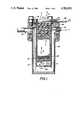
- FIG. 1is an enlarged cross-sectional view of a single circuit cryostat with a heat exchanger according to the present invention.
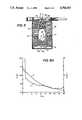
- FIG. 2is an enlarged cross-sectional view of a large diameter single circuit cryostat according to the present invention.
- FIG. 3is an enlarged cross-sectional view of a cryostat employing a dual circuit heat exchanger according to the present invention.
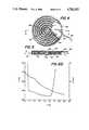
- FIG. 4is a top plan view of a cryostat employing a heat exchanger according to the present invention.
- FIG. 5is a view taken along the line 5--5 of FIG. 4.
- FIG. 6Ais a plot of temperature and pressure versus time for a cryostat employing a heat exchanger according to the prior art.
- FIG. 6Bis a plot of temperature and pressure versus time for a cryostat employing a heat exchanger according to the present invention.
- J-TJoule-Thomson
- Conventional cryostatsemploy a heat exchanger generally constructed by wrapping a small diameter finned tube around a mandrel.
- the finned tubeterminates in a Joule-Thomson orifice.
- the tube and mandrel structureis placed inside of a dewar or sleeve so that high pressure fluid conducted down through the finned tube and expanded through the Joule-Thomson orifice is forced to leave the area of the Joule-Thomson orifice by flowing over the finned tube to precool the entering high pressure fluid.
- the finely dividend matrixis made up of a plurality of fine wires arrayed in the form of a layering of fine wire mesh screens.
- the use of mesh for heat transfermakes the refrigerator smaller and lighter than those of previous design. It is axiomatic that a lighter refrigerator cools faster. However, with the low-pressure gas, adequate heat exchange is much more difficult.
- the heat exchange surface for the low-pressure gasmust be light weight (therefore, high surface-to-volume ratio), have a high heat transfer coefficient, and have small pressure drop. Tightly spaced fine copper wires are the best media for that critical heat exchange surface.
- the low pressure gasin order to keep the pressure drop at a minimum it is essential that the low pressure gas not be confined in a tight geometry where its velocity becomes large. This is especially true because the pressure drop in a given media is proportional to its velocity to the 1.75 or second power.
- the advantages of going to a fine wire matrixare manifest in several ways.
- the surface-to-volume ratiogoes up (this ratio can be shown to be 4/d for long wires).
- the heat transfer coefficient (h)goes up as the wire size decreases as disclosed in the publication Heat Transmission by W. H. McAdams published by McGraw-Hill, New York, N.Y. (1932) wherein the author shows that h equals (k/d) [0.32+0.43 (d G/ ⁇ ) 0 .52 ] where k is the gas conductivity, ⁇ is its viscosity, and G its mass flow rate.
- Heat transfer coefficients in screensfollow a relation similar to that in wires, except that it is more complicated since it involves taking into consideration the mesh size of the screen.
- a heat exchanger 10includes a matrix 12 which can be constructed from a plurality of fine wire mesh screens of a highly conductive material such as copper. Screens having a mesh size of approximately 100 have been found to be particularly effective, but the mesh size can be varied depending upon the performance characteristics for the desired cryostat. Preferably the screens are layered and each screen is oriented 45° to its neighbor to define the flow path as shown by the arrows in FIG. 1. While the preferred embodiment employes fine wire mesh screens, other finely divided materials such as layered wires, sintered porous metals and the like can be used in place thereof. Disposed around and fixed to the matrix 12 in good heat exchange relation therewith is a small diameter capillary tube 14.
- the capillary tube 14is preferably fabricated from an alloy of copper having good thermal conductivity. Capillary tube 14 is disposed in such a manner to define an inlet or warm end 16 and an outlet or cold end 18 for the heat exchanger 10. Conventionally cold end 18 terminates in a Joule-Thomson (J-T) orifice (not shown) as is well known in the art.
- J-TJoule-Thomson
- a heat exchanger 10can be disposed inside of a stainless steel sleeve 20 having an end cap 22 on one end so that when the heat exchanger 10 is inserted in the sleeve there is a space between the cold end 18 of the heat exchanger and the cap 20 for accumulation of liquefied and/or cold fluid.
- the cap 22includes a temperature sensor (or detector) 24 which is connected via conventional electrical feeds 26 to a temperature monitoring device (not shown).
- the sleeve 20 and heat exchanger 10 which define a cryostatare disposed inside of a vacuum housing 28 which in turn is fixed to a flange 30 which in turn is held in vacuum tight relationship to a test adaptor 32.
- Vacuum housing 28includes suitable feed through ports 34 for the electrical conduits and a vacuum pump out port 36 to evacuate the housing to thus measure the effectiveness of the heat exchanger 10.
- the materials of construction of a heat exchanger according to the present inventionare generally available from custom metal houses.
- the materials of constructionwill depend upon the dimensions of the cryostat and the performance characteristics required.
- cryostats according to FIG. 1were constructed and tested utilizing various high pressure fluids.
- the cryostatswere connected to a source of high pressure gas via the inlet conduit 38 which is held in fluid tight relation to inlet end 16 of the capillary tube 14 with fluid flows shown by arrows F H for high pressure and F L for low pressure.
- the inlet gas pressure for the test set upwas 6,000 psi at the commencement of the test. It is important to note that it is not necessary to cool the cold end 18 of the heat exchanger all the way to 87° K. or 77° K. in order to produce refrigeration at 87° K. or 77° K. at the bottom of the sleeve with argon or nitrogen gas respectively.
- the 6,000 psi fluid reaching the Joule-Thomson orifice on the cold end 18 of the heat exchanger 10is cooled to 220° K. or 180° K. with argon or nitrogen, it produces a mixture of the respective liquefied gas and gaseous argon or nitrogen upon expansion to low pressure.
- FIGS. 6A and 6Brespectively there is shown a plot of temperature and pressure versus time for, in the case of FIG. 6A, a cryostat with a conventional finned tube heat exchanger such as disclosed in any of the cited prior art and, in the case of FIG. 6B, a cryostat with a heat exchanger according to the present invention.
- the heat exchangerhad an outside diameter of 0.130 inches and was 1.2 inches long and the cryostat of FIG. 6B was of the same diameter with a length of 0.36 inches.
- the testswere run and temperature measured with no vacuum jacketing of the heat exchanger. As is apparent from a comparison of FIGS.
- the cryostat with the heat exchanger according to the present inventionachieves a temperature of 95° K. in slightly less than 1 second whereas the cryostat of the prior art requires almost 4 seconds to achieve the same temperature. Therefore, a fast cooldown cryostat can be achieved by embodying the heat exchanger of the present invention.
- FIG. 2there is shown a large diameter cryostat wherein the heat exchanger 40 is constructed by utilizing a plurality of stacked inner screens 42 around which is disposed the capillary tube 44. Disposed around the capillary 44 is a second set of stacked screens 46.
- the materials of constructioncan be the same for the heat exchanger of FIG. 2 as for the heat exchanger of FIG. 1.
- the heat exchanger of FIG. 2can be disposed within a stainless steel sleeve 48 which has an end cap 50 and which can be disposed in a vacuum housing 52 to be tested in accordance with the test method of the device of FIG. 1.
- the device of FIG. 2shows fluid flow using the same nomenclature as in FIG. 1. Comparatively speaking the heat exchanger of FIG. 1 would have an outside diameter of 0.130 inches and a length of 0.40 inches whereas the heat exchanger of FIG. 2 can have an outside diameter of 0.326 inches and a length of 0.60 inches.
- FIG. 3A two-stage cryostat according to the present invention is shown in FIG. 3 wherein there is employed a first heat exchanger 60 which is constructed by stacking a plurality of screens 62 around which is disposed a capillary 64 such as shown and described in relation to FIG. 1.
- a second heat exchanger 70Disposed around a portion of the first heat exchanger 60 is a second heat exchanger 70 which is constructed from a plurality of stacked annular screens 72 around which is disposed a capillary 74.
- the second heat exchanger 70is constructed so that its total length is less than that of heat exchanger 60 and it encircles only a portion of heat exchanger 60 from the warm end 66 toward the cold end 68 of the heat exchanger 60.
- the dual heat exchanger 60-70can be disposed inside of a stainless steel sleeve 76.
- the projecting end of heat exchanger 60can be kept in position inside sleeve 76 by a foam spacer 78.
- the dual heat exchanger of FIG. 3including a first JT orifice 61 for tube 64 of heat exchanger 60 and a second JT orifice 71 for tube 74 of heat exchanger 70 with the first heat exchanger capillary 64 connected to a source of high pressure fluid such as neon at 100 atmospheres and a second capillary 74 connected to a source of nitrogen at 400 atmospheres with both gases being at a temperature of approximately 300° kelvin (°K.) will produce a temperature of approximately 30° kelvin at the bottom 68 of heat exchanger 60 when tested as shown.
- a temperature of approximately 83° kelvinis achieved at the bottom of a device according to FIG. 3 if capillary 64 is connected to N 2 and capillary 74 is connected to CF 4 .
- a device according to FIG. 3can produce different temperatures at the cold end 68 of heat exchanger 60 by utilizing various combinations of gases (cryogens) as set forth in Table 2.
- the heat exchanger according to the present inventioncan be embodied in the form of a flat disc for embodiment into a low profile configuration.
- the heat exchanger 80is constructed by providing an annulus of fine mesh screens 82 which can be fabricated by wrapping the screening around a removeable mandrel. Disposed along one side of the annulus of screens 82 is a capillary 84 which terminates in a Joule-Thomson orifice 86 inside of the annulus of screens 82.
- the screen and capillary constructionis closed by a pair of spaced apart stainless steel discs 88 and 90 so that high pressure fluid shown by arrow F H conducted from the inlet 92 of capillary 84 to the Joule-Thomson orifice 86 flows radially outwardly between discs 88 80 as shown by the arrow F L .
- the screening 82can be achieved by spirally winding one hundred mesh copper screen around a mandrel.
- final assemblycan be by any conventional technique such as furnace brazing of the assembly.
- the assembled device of FIGS. 4 and 5can be used with a detector to be cooled placed as shown as item 94.
Landscapes
- Engineering & Computer Science (AREA)
- Physics & Mathematics (AREA)
- Thermal Sciences (AREA)
- Mechanical Engineering (AREA)
- General Engineering & Computer Science (AREA)
- Chemical & Material Sciences (AREA)
- Dispersion Chemistry (AREA)
- Health & Medical Sciences (AREA)
- Clinical Laboratory Science (AREA)
Abstract
Description
TABLE 1 ______________________________________ Exchanger OD-in. .130 → → → .204 .130 Matrix Material copper → → → → → Mesh 100 → → 100/150.sup.(2) 100 100 # Layers 100 → → → → 150 Orientation.sup.(1) 45° → → Parallel 45° 45° OD-in. .108 → → → .182 .108 Tube Material St. Stl. → → → → → OD-in. .013 → → → → → ID-in. .007 → → → → → # Turns 23 23 23 23 23 34 Orifice 2.5 → → → → → Co - l/M.sup.(3) Gas N.sub.2 Ar CF.sub.4 Ar Ar Ar Performance NTU.sup.(4) 4 5.2 3.9 6.2 7.3 7.8 CDT.sup.(5) 2.4 .3 .1 .3 .3 .3 T.sup.(6)K 84 94 151 96 89 96 ______________________________________ .sup.(1) 45° means that the wires in each layer of screen are rotated 45° with respect to the adjacent layers. .sup.(2) A 100mesh screen is alternated with a 150mesh screen with wires in adjacent screens parallel. .sup.(3) Co = flow rate measured at room temperature with 1000 psi N.sub.2. .sup.(4) NTU = number of transfer units. .sup.(5) CDT = calculated cooldown time, with very light cold end caps. .sup.(6) T = calculated temperature at cooldown.
TABLE 2 ______________________________________ Test No.Capillary 64Capillary 74 Minimum Temp °K. ______________________________________ 1 CF.sub.3Cl AR 90 2 CF.sub.4AR 90 3 CF.sub.3 Cl N.sub.2 83 4 CF.sub.4 N.sub.2 83 5 CF.sub.4 N.sub.2 /Ne 75 6 AR N.sub.2 /Ne 75 7AIR Ne 32 8 N.sub.2Ne 32 9 AIR H.sub.2 25 10 N.sub.2 H.sub.2 25 ______________________________________
Claims (16)
Priority Applications (1)
| Application Number | Priority Date | Filing Date | Title |
|---|---|---|---|
| US07/074,303US4781033A (en) | 1987-07-16 | 1987-07-16 | Heat exchanger for a fast cooldown cryostat |
Applications Claiming Priority (1)
| Application Number | Priority Date | Filing Date | Title |
|---|---|---|---|
| US07/074,303US4781033A (en) | 1987-07-16 | 1987-07-16 | Heat exchanger for a fast cooldown cryostat |
Publications (1)
| Publication Number | Publication Date |
|---|---|
| US4781033Atrue US4781033A (en) | 1988-11-01 |
Family
ID=22118855
Family Applications (1)
| Application Number | Title | Priority Date | Filing Date |
|---|---|---|---|
| US07/074,303Expired - LifetimeUS4781033A (en) | 1987-07-16 | 1987-07-16 | Heat exchanger for a fast cooldown cryostat |
Country Status (1)
| Country | Link |
|---|---|
| US (1) | US4781033A (en) |
Cited By (48)
| Publication number | Priority date | Publication date | Assignee | Title |
|---|---|---|---|---|
| US5012650A (en)* | 1989-10-11 | 1991-05-07 | Apd Cryogenics, Inc. | Cryogen thermal storage matrix |
| US5056317A (en)* | 1988-04-29 | 1991-10-15 | Stetson Norman B | Miniature integral Stirling cryocooler |
| US5243826A (en)* | 1992-07-01 | 1993-09-14 | Apd Cryogenics Inc. | Method and apparatus for collecting liquid cryogen |
| US5249425A (en)* | 1992-07-01 | 1993-10-05 | Apd Cryogenics Inc. | Venting control system for cryostats |
| US5299425A (en)* | 1991-10-30 | 1994-04-05 | Bodenseewerk Geratetechnik Gmbh | Cooling apparatus |
| US5313801A (en)* | 1992-07-07 | 1994-05-24 | Apd Cryogenics, Inc. | Cryostat throttle |
| US5590538A (en)* | 1995-11-16 | 1997-01-07 | Lockheed Missiles And Space Company, Inc. | Stacked multistage Joule-Thomson cryostat |
| US5758505A (en)* | 1995-10-12 | 1998-06-02 | Cryogen, Inc. | Precooling system for joule-thomson probe |
| US5787715A (en)* | 1995-10-12 | 1998-08-04 | Cryogen, Inc. | Mixed gas refrigeration method |
| US5787713A (en)* | 1996-06-28 | 1998-08-04 | American Superconductor Corporation | Methods and apparatus for liquid cryogen gasification utilizing cryoelectronics |
| US5901783A (en)* | 1995-10-12 | 1999-05-11 | Croyogen, Inc. | Cryogenic heat exchanger |
| FR2782785A1 (en)* | 1998-08-27 | 2000-03-03 | Air Liquide | JOULE-THOMSON COOLER |
| US6151901A (en)* | 1995-10-12 | 2000-11-28 | Cryogen, Inc. | Miniature mixed gas refrigeration system |
| US6173577B1 (en) | 1996-08-16 | 2001-01-16 | American Superconductor Corporation | Methods and apparatus for cooling systems for cryogenic power conversion electronics |
| US6182666B1 (en) | 1996-12-26 | 2001-02-06 | Cryogen, Inc. | Cryosurgical probe and method for uterine ablation |
| US6270494B1 (en) | 1996-12-26 | 2001-08-07 | Cryogen, Inc. | Stretchable cryoprobe sheath |
| US6306129B1 (en) | 1997-09-22 | 2001-10-23 | Femrx, Inc. | Cryosurgical system and method |
| US20030000213A1 (en)* | 1999-12-17 | 2003-01-02 | Christensen Richard N. | Heat engine |
| US6530234B1 (en) | 1995-10-12 | 2003-03-11 | Cryogen, Inc. | Precooling system for Joule-Thomson probe |
| US6585752B2 (en) | 1998-06-23 | 2003-07-01 | Innercool Therapies, Inc. | Fever regulation method and apparatus |
| US6602276B2 (en) | 1998-03-31 | 2003-08-05 | Innercool Therapies, Inc. | Method and device for performing cooling- or cryo-therapies for, e.g., angioplasty with reduced restenosis or pulmonary vein cell necrosis to inhibit atrial fibrillation |
| EP1092966A3 (en)* | 1999-09-23 | 2003-10-01 | Rafael - Armament Development Authority Ltd. | Infrared detector |
| US6660028B2 (en) | 2000-06-02 | 2003-12-09 | Innercool Therapies, Inc. | Method for determining the effective thermal mass of a body or organ using a cooling catheter |
| US6685732B2 (en) | 1998-03-31 | 2004-02-03 | Innercool Therapies, Inc. | Method and device for performing cooling- or cryo-therapies for, e.g., angioplasty with reduced restenosis or pulmonary vein cell necrosis to inhibit atrial fibrillation employing microporous balloon |
| US6719779B2 (en) | 2000-11-07 | 2004-04-13 | Innercool Therapies, Inc. | Circulation set for temperature-controlled catheter and method of using the same |
| US6905494B2 (en) | 1998-03-31 | 2005-06-14 | Innercool Therapies, Inc. | Method and device for performing cooling- or cryo-therapies for, e.g., angioplasty with reduced restenosis or pulmonary vein cell necrosis to inhibit atrial fibrillation employing tissue protection |
| US20050198972A1 (en)* | 2004-03-10 | 2005-09-15 | Lentz David J. | Pressure-temperature control for a cryoablation catheter system |
| US7001378B2 (en) | 1998-03-31 | 2006-02-21 | Innercool Therapies, Inc. | Method and device for performing cooling or cryo-therapies, for, e.g., angioplasty with reduced restenosis or pulmonary vein cell necrosis to inhibit atrial fibrillation employing tissue protection |
| US20070107446A1 (en)* | 2005-09-09 | 2007-05-17 | Bruker Biospin Gmbh | Superconducting magnet system with refrigerator for re-liquifying cryogenic fluid in a tubular conduit |
| US7291144B2 (en) | 1998-03-31 | 2007-11-06 | Innercool Therapies, Inc. | Method and device for performing cooling- or cryo-therapies for, e.g., angioplasty with reduced restenosis or pulmonary vein cell necrosis to inhibit atrial fibrillation |
| US7300453B2 (en) | 2003-02-24 | 2007-11-27 | Innercool Therapies, Inc. | System and method for inducing hypothermia with control and determination of catheter pressure |
| US7347057B1 (en) | 2003-12-12 | 2008-03-25 | Cooling Technologies, Inc. | Control of dual-heated absorption heat-transfer machines |
| US20080184711A1 (en)* | 2007-02-01 | 2008-08-07 | Diehl Bgt Defence Gmbh & Co. Kg | Method for Cooling a Detector |
| US20090000313A1 (en)* | 2003-05-23 | 2009-01-01 | Flir Systems Inc. | Regenerator matrix with mixed screen configuration |
| US20100330316A1 (en)* | 2009-06-25 | 2010-12-30 | Nomaco Inc. | Self-adjusting insulation, including insulation particularly suited for pipe or duct |
| US8163000B2 (en) | 1998-01-23 | 2012-04-24 | Innercool Therapies, Inc. | Selective organ cooling catheter with guidewire apparatus and temperature-monitoring device |
| US20120132393A1 (en)* | 2009-08-03 | 2012-05-31 | Skanska Sverige Ab | Arrangement and method for storing thermal energy |
| CN102741967A (en)* | 2010-02-02 | 2012-10-17 | 微技术有限责任公司 | X-ray tube |
| US20130306279A1 (en)* | 2012-05-15 | 2013-11-21 | Lockheed Martin Corporation - Missiles and Fire Control | System, apparatus, and method for micro-capillary heat exchanger |
| US20140090404A1 (en)* | 2012-02-08 | 2014-04-03 | Quantum Design, Inc. | Cryocooler-based gas scrubber |
| WO2014150680A1 (en)* | 2013-03-15 | 2014-09-25 | Deluca Oven Technologies, Llc | Liquid heater including wire mesh heating segment |
| US9157566B2 (en) | 2012-05-11 | 2015-10-13 | Nomaco Inc. | Insulation systems employing expansion features to insulate elongated containers subject to extreme temperature fluctuations, and related components and methods |
| US9683766B1 (en) | 2013-07-12 | 2017-06-20 | Lockheed Martin Corporation | System and method for electronic de-clogging of microcoolers |
| FR3052245A1 (en)* | 2016-06-06 | 2017-12-08 | Soc Fr De Detecteurs Infrarouges - Sofradir | CRYOGENIC DEVICE WITH COMPACT EXCHANGER |
| US9863670B2 (en) | 2011-09-20 | 2018-01-09 | Lockheed Martin Corporation | Extended travel flexure bearing and micro check valve |
| US9999885B1 (en) | 2014-05-30 | 2018-06-19 | Lockheed Martin Corporation | Integrated functional and fluidic circuits in Joule-Thompson microcoolers |
| US20190137185A1 (en)* | 2016-05-12 | 2019-05-09 | Linde Aktiengesellschaft | Coiled heat exchanger having inserts between the shroud and the last pipe layer |
| US11287171B1 (en) | 2017-07-05 | 2022-03-29 | Rigetti & Co, Llc | Heat switches for controlling a flow of heat between thermal stages of a cryostat |
Citations (9)
| Publication number | Priority date | Publication date | Assignee | Title |
|---|---|---|---|---|
| US3704601A (en)* | 1969-03-25 | 1972-12-05 | Hymatic Eng Co Ltd | Cryogenic cooling apparatus |
| US3795116A (en)* | 1970-03-31 | 1974-03-05 | Alsthom Cgee | Method and apparatus for supercooling of electrical devices |
| US3800552A (en)* | 1972-03-29 | 1974-04-02 | Bendix Corp | Cryogenic surgical instrument |
| US3942010A (en)* | 1966-05-09 | 1976-03-02 | The United States Of America As Represented By The Secretary Of The Navy | Joule-Thomson cryostat cooled infrared cell having a built-in thermostat sensing element |
| US4235078A (en)* | 1978-03-16 | 1980-11-25 | Officine Galileo S.P.A. | Cryogenic equipment for very low temperatures |
| US4259844A (en)* | 1979-07-30 | 1981-04-07 | Helix Technology Corporation | Stacked disc heat exchanger for refrigerator cold finger |
| US4429732A (en)* | 1982-07-28 | 1984-02-07 | Moscrip William M | Regenerator structure for stirling-cycle, reciprocating thermal machines |
| US4487253A (en)* | 1980-11-12 | 1984-12-11 | Vyzkumny Ustav Silnoproude Elektrotechniky | Heat exchanger for cryosurgical instruments |
| US4569210A (en)* | 1984-07-30 | 1986-02-11 | Societe Anonyme De Telecommunications | Cooling controller utilizing the Joule-Thomson effect |
- 1987
- 1987-07-16USUS07/074,303patent/US4781033A/ennot_activeExpired - Lifetime
Patent Citations (9)
| Publication number | Priority date | Publication date | Assignee | Title |
|---|---|---|---|---|
| US3942010A (en)* | 1966-05-09 | 1976-03-02 | The United States Of America As Represented By The Secretary Of The Navy | Joule-Thomson cryostat cooled infrared cell having a built-in thermostat sensing element |
| US3704601A (en)* | 1969-03-25 | 1972-12-05 | Hymatic Eng Co Ltd | Cryogenic cooling apparatus |
| US3795116A (en)* | 1970-03-31 | 1974-03-05 | Alsthom Cgee | Method and apparatus for supercooling of electrical devices |
| US3800552A (en)* | 1972-03-29 | 1974-04-02 | Bendix Corp | Cryogenic surgical instrument |
| US4235078A (en)* | 1978-03-16 | 1980-11-25 | Officine Galileo S.P.A. | Cryogenic equipment for very low temperatures |
| US4259844A (en)* | 1979-07-30 | 1981-04-07 | Helix Technology Corporation | Stacked disc heat exchanger for refrigerator cold finger |
| US4487253A (en)* | 1980-11-12 | 1984-12-11 | Vyzkumny Ustav Silnoproude Elektrotechniky | Heat exchanger for cryosurgical instruments |
| US4429732A (en)* | 1982-07-28 | 1984-02-07 | Moscrip William M | Regenerator structure for stirling-cycle, reciprocating thermal machines |
| US4569210A (en)* | 1984-07-30 | 1986-02-11 | Societe Anonyme De Telecommunications | Cooling controller utilizing the Joule-Thomson effect |
Cited By (80)
| Publication number | Priority date | Publication date | Assignee | Title |
|---|---|---|---|---|
| US5056317A (en)* | 1988-04-29 | 1991-10-15 | Stetson Norman B | Miniature integral Stirling cryocooler |
| US5012650A (en)* | 1989-10-11 | 1991-05-07 | Apd Cryogenics, Inc. | Cryogen thermal storage matrix |
| US5299425A (en)* | 1991-10-30 | 1994-04-05 | Bodenseewerk Geratetechnik Gmbh | Cooling apparatus |
| US5243826A (en)* | 1992-07-01 | 1993-09-14 | Apd Cryogenics Inc. | Method and apparatus for collecting liquid cryogen |
| US5249425A (en)* | 1992-07-01 | 1993-10-05 | Apd Cryogenics Inc. | Venting control system for cryostats |
| WO1994001728A1 (en)* | 1992-07-01 | 1994-01-20 | Apd Cryogenics Inc. | Method and apparatus for collecting liquid cryogen |
| US5313801A (en)* | 1992-07-07 | 1994-05-24 | Apd Cryogenics, Inc. | Cryostat throttle |
| US5956958A (en)* | 1995-10-12 | 1999-09-28 | Cryogen, Inc. | Gas mixture for cryogenic applications |
| US5758505A (en)* | 1995-10-12 | 1998-06-02 | Cryogen, Inc. | Precooling system for joule-thomson probe |
| US5787715A (en)* | 1995-10-12 | 1998-08-04 | Cryogen, Inc. | Mixed gas refrigeration method |
| US5901783A (en)* | 1995-10-12 | 1999-05-11 | Croyogen, Inc. | Cryogenic heat exchanger |
| US6530234B1 (en) | 1995-10-12 | 2003-03-11 | Cryogen, Inc. | Precooling system for Joule-Thomson probe |
| US6151901A (en)* | 1995-10-12 | 2000-11-28 | Cryogen, Inc. | Miniature mixed gas refrigeration system |
| US5590538A (en)* | 1995-11-16 | 1997-01-07 | Lockheed Missiles And Space Company, Inc. | Stacked multistage Joule-Thomson cryostat |
| US5787713A (en)* | 1996-06-28 | 1998-08-04 | American Superconductor Corporation | Methods and apparatus for liquid cryogen gasification utilizing cryoelectronics |
| US6092372A (en)* | 1996-06-28 | 2000-07-25 | Russo; Carl J. | Methods and apparatus for liquid cryogen gasification |
| US6173577B1 (en) | 1996-08-16 | 2001-01-16 | American Superconductor Corporation | Methods and apparatus for cooling systems for cryogenic power conversion electronics |
| US6270494B1 (en) | 1996-12-26 | 2001-08-07 | Cryogen, Inc. | Stretchable cryoprobe sheath |
| US6193644B1 (en) | 1996-12-26 | 2001-02-27 | Cryogen, Inc. | Cryosurgical probe with sheath |
| US6182666B1 (en) | 1996-12-26 | 2001-02-06 | Cryogen, Inc. | Cryosurgical probe and method for uterine ablation |
| US6451012B2 (en) | 1996-12-26 | 2002-09-17 | Cryogen, Inc. | Cryosurgical method for endometrial ablation |
| US6475212B2 (en) | 1996-12-26 | 2002-11-05 | Cryogen, Inc. | Cryosurgical probe with sheath |
| US6306129B1 (en) | 1997-09-22 | 2001-10-23 | Femrx, Inc. | Cryosurgical system and method |
| US7766949B2 (en) | 1998-01-23 | 2010-08-03 | Innercool Therapies, Inc. | Fever regulation method and apparatus |
| US8163000B2 (en) | 1998-01-23 | 2012-04-24 | Innercool Therapies, Inc. | Selective organ cooling catheter with guidewire apparatus and temperature-monitoring device |
| US7094253B2 (en) | 1998-01-23 | 2006-08-22 | Innercool Therapies, Inc. | Fever regulation method and apparatus |
| US7291144B2 (en) | 1998-03-31 | 2007-11-06 | Innercool Therapies, Inc. | Method and device for performing cooling- or cryo-therapies for, e.g., angioplasty with reduced restenosis or pulmonary vein cell necrosis to inhibit atrial fibrillation |
| US7288089B2 (en) | 1998-03-31 | 2007-10-30 | Innercool Therapies, Inc. | Method and device for performing cooling- or cryo-therapies for, e.g., angioplasty with reduced restenosis or pulmonary vein cell necrosis to inhibit atrial fibrillation employing tissue protection |
| US8157794B2 (en) | 1998-03-31 | 2012-04-17 | Innercool Therapies, Inc. | Method and device for performing cooling-or cryo-therapies for, e.g., angioplasty with reduced restenosis or pulmonary vein cell necrosis to inhibit atrial fibrillation |
| US7449018B2 (en) | 1998-03-31 | 2008-11-11 | Innercool Therapies, Inc. | Method and device for performing cooling- or cryo-therapies for, e.g., angioplasty with reduced restenosis or pulmonary vein cell necrosis to inhibit atrial fibrillation employing microporous balloon |
| US6685732B2 (en) | 1998-03-31 | 2004-02-03 | Innercool Therapies, Inc. | Method and device for performing cooling- or cryo-therapies for, e.g., angioplasty with reduced restenosis or pulmonary vein cell necrosis to inhibit atrial fibrillation employing microporous balloon |
| US8043351B2 (en) | 1998-03-31 | 2011-10-25 | Innercool Therapies, Inc. | Method and device for performing cooling- or cryo-therapies for, e.g., angioplasty with reduced restenosis or pulmonary vein cell necrosis to inhibit atrial fibrillation employing tissue protection |
| US6905494B2 (en) | 1998-03-31 | 2005-06-14 | Innercool Therapies, Inc. | Method and device for performing cooling- or cryo-therapies for, e.g., angioplasty with reduced restenosis or pulmonary vein cell necrosis to inhibit atrial fibrillation employing tissue protection |
| US6602276B2 (en) | 1998-03-31 | 2003-08-05 | Innercool Therapies, Inc. | Method and device for performing cooling- or cryo-therapies for, e.g., angioplasty with reduced restenosis or pulmonary vein cell necrosis to inhibit atrial fibrillation |
| US7001378B2 (en) | 1998-03-31 | 2006-02-21 | Innercool Therapies, Inc. | Method and device for performing cooling or cryo-therapies, for, e.g., angioplasty with reduced restenosis or pulmonary vein cell necrosis to inhibit atrial fibrillation employing tissue protection |
| US8043283B2 (en) | 1998-03-31 | 2011-10-25 | Innercool Therapies, Inc. | Method and device for performing cooling- or cryo-therapies for, e.g., angioplasty with reduced restenosis or pulmonary vein cell necrosis to inhibit atrial fibrillation |
| US6585752B2 (en) | 1998-06-23 | 2003-07-01 | Innercool Therapies, Inc. | Fever regulation method and apparatus |
| FR2782785A1 (en)* | 1998-08-27 | 2000-03-03 | Air Liquide | JOULE-THOMSON COOLER |
| US6202422B1 (en) | 1998-08-27 | 2001-03-20 | L'air Liquide, Societe Anonyme Pour L'etude Et L'exploitation Des Procedes Georges Claude | Joule-Thomson cooler |
| EP1092966A3 (en)* | 1999-09-23 | 2003-10-01 | Rafael - Armament Development Authority Ltd. | Infrared detector |
| US20030000213A1 (en)* | 1999-12-17 | 2003-01-02 | Christensen Richard N. | Heat engine |
| US7211105B2 (en) | 2000-06-02 | 2007-05-01 | Innercool Therapias, Inc. | Method for determining the effective thermal mass of a body or organ using a cooling catheter |
| US6660028B2 (en) | 2000-06-02 | 2003-12-09 | Innercool Therapies, Inc. | Method for determining the effective thermal mass of a body or organ using a cooling catheter |
| US6719779B2 (en) | 2000-11-07 | 2004-04-13 | Innercool Therapies, Inc. | Circulation set for temperature-controlled catheter and method of using the same |
| US7004960B2 (en) | 2000-11-07 | 2006-02-28 | Innercool Therapies, Inc. | Circulation set for temperature-controlled catheter and method of using the same |
| US7300453B2 (en) | 2003-02-24 | 2007-11-27 | Innercool Therapies, Inc. | System and method for inducing hypothermia with control and determination of catheter pressure |
| US20090000313A1 (en)* | 2003-05-23 | 2009-01-01 | Flir Systems Inc. | Regenerator matrix with mixed screen configuration |
| US7347057B1 (en) | 2003-12-12 | 2008-03-25 | Cooling Technologies, Inc. | Control of dual-heated absorption heat-transfer machines |
| US20050198972A1 (en)* | 2004-03-10 | 2005-09-15 | Lentz David J. | Pressure-temperature control for a cryoablation catheter system |
| US20070107446A1 (en)* | 2005-09-09 | 2007-05-17 | Bruker Biospin Gmbh | Superconducting magnet system with refrigerator for re-liquifying cryogenic fluid in a tubular conduit |
| US20080184711A1 (en)* | 2007-02-01 | 2008-08-07 | Diehl Bgt Defence Gmbh & Co. Kg | Method for Cooling a Detector |
| US20100330316A1 (en)* | 2009-06-25 | 2010-12-30 | Nomaco Inc. | Self-adjusting insulation, including insulation particularly suited for pipe or duct |
| US8658264B2 (en) | 2009-06-25 | 2014-02-25 | Nomaco Inc. | Self-adjusting insulation, including insulation particularly suited for pipe or duct |
| US8261558B2 (en)* | 2009-06-25 | 2012-09-11 | Nomaco Inc. | Self-adjusting insulation, including insulation particularly suited for pipe or duct |
| US20120132393A1 (en)* | 2009-08-03 | 2012-05-31 | Skanska Sverige Ab | Arrangement and method for storing thermal energy |
| US9709337B2 (en)* | 2009-08-03 | 2017-07-18 | Skanska Sverige Ab | Arrangement for storing thermal energy |
| CN102741967B (en)* | 2010-02-02 | 2015-11-25 | 微技术有限责任公司 | X-ray tube |
| US20120328081A1 (en)* | 2010-02-02 | 2012-12-27 | Microtec S.R.L. | X-ray tube |
| CN102741967A (en)* | 2010-02-02 | 2012-10-17 | 微技术有限责任公司 | X-ray tube |
| US9863670B2 (en) | 2011-09-20 | 2018-01-09 | Lockheed Martin Corporation | Extended travel flexure bearing and micro check valve |
| US10254017B2 (en) | 2011-09-20 | 2019-04-09 | Lockheed Martin Corporation | Extended travel flexure bearing and micro check valve |
| US20140090404A1 (en)* | 2012-02-08 | 2014-04-03 | Quantum Design, Inc. | Cryocooler-based gas scrubber |
| US10113793B2 (en)* | 2012-02-08 | 2018-10-30 | Quantum Design International, Inc. | Cryocooler-based gas scrubber |
| US9157566B2 (en) | 2012-05-11 | 2015-10-13 | Nomaco Inc. | Insulation systems employing expansion features to insulate elongated containers subject to extreme temperature fluctuations, and related components and methods |
| US9784505B2 (en)* | 2012-05-15 | 2017-10-10 | Lockheed Martin Corporation | System, apparatus, and method for micro-capillary heat exchanger |
| US20130306279A1 (en)* | 2012-05-15 | 2013-11-21 | Lockheed Martin Corporation - Missiles and Fire Control | System, apparatus, and method for micro-capillary heat exchanger |
| WO2014150680A1 (en)* | 2013-03-15 | 2014-09-25 | Deluca Oven Technologies, Llc | Liquid heater including wire mesh heating segment |
| US9683766B1 (en) | 2013-07-12 | 2017-06-20 | Lockheed Martin Corporation | System and method for electronic de-clogging of microcoolers |
| US9999885B1 (en) | 2014-05-30 | 2018-06-19 | Lockheed Martin Corporation | Integrated functional and fluidic circuits in Joule-Thompson microcoolers |
| US10914526B2 (en)* | 2016-05-12 | 2021-02-09 | Linde Aktiengesellschaft | Coiled heat exchanger having inserts between the shroud and the last pipe layer |
| US20190137185A1 (en)* | 2016-05-12 | 2019-05-09 | Linde Aktiengesellschaft | Coiled heat exchanger having inserts between the shroud and the last pipe layer |
| CN109073293A (en)* | 2016-06-06 | 2018-12-21 | 法国红外探测器公司 | Cryo Equipment with compact exchanger |
| KR20190015202A (en)* | 2016-06-06 | 2019-02-13 | 소시에떼 프랑세즈 뒤 드테끄퇴르 인프라루즈 소프라디르 | Cryogenic apparatus with a compact exchanger |
| US20190120529A1 (en)* | 2016-06-06 | 2019-04-25 | Societe Francaise De Detecteurs Infrarouges- Sofradir | Cryogenic device with compact exchanger |
| WO2017212148A1 (en)* | 2016-06-06 | 2017-12-14 | Societe Francaise De Detecteurs Infrarouges - Sofradir | Cryogenic device with compact exchanger |
| CN109073293B (en)* | 2016-06-06 | 2020-07-03 | 法国红外探测器公司 | Refrigerating device implementing joule-thomson expansion principle |
| FR3052245A1 (en)* | 2016-06-06 | 2017-12-08 | Soc Fr De Detecteurs Infrarouges - Sofradir | CRYOGENIC DEVICE WITH COMPACT EXCHANGER |
| KR102260700B1 (en)* | 2016-06-06 | 2021-06-03 | 린레드 | Cryogenic unit with compact exchanger |
| US11287171B1 (en) | 2017-07-05 | 2022-03-29 | Rigetti & Co, Llc | Heat switches for controlling a flow of heat between thermal stages of a cryostat |
| US12270592B1 (en) | 2017-07-05 | 2025-04-08 | Rigetti & Co, Llc | Heat switches for controlling a flow of heat between thermal stages of a cryostat |
Similar Documents
| Publication | Publication Date | Title |
|---|---|---|
| US4781033A (en) | Heat exchanger for a fast cooldown cryostat | |
| CA1285781C (en) | Cryogenic recondenser with remote cold box | |
| US3320755A (en) | Cryogenic refrigeration system | |
| US4696168A (en) | Refrigerant subcooler for air conditioning systems | |
| EP0447861B1 (en) | Two-stage Joule-Thomson cryostat with gas supply management system, and uses thereof | |
| US4785879A (en) | Parallel wrapped tube heat exchanger | |
| JP2004537026A (en) | Apparatus for recondensing low-boiling gas of liquefied gas-gas evaporating from vessel using cryo-generator | |
| US4484458A (en) | Apparatus for condensing liquid cryogen boil-off | |
| US10309718B2 (en) | Small-scale hydrogen liquefaction system equipped with cryocooler | |
| GB1217236A (en) | Method and apparatus for continuously supplying refrigeration below 4.2°k | |
| US3401533A (en) | Gas liquefiers | |
| US3431750A (en) | Gas-expansion refrigerator | |
| US20040187519A1 (en) | Cryogenic refrigerator | |
| US3415078A (en) | Infrared detector cooler | |
| US4825667A (en) | Cryogenic cooling system | |
| US4697635A (en) | Parallel wrapped tube heat exchanger | |
| US4020274A (en) | Superconducting cable cooling system by helium gas and a mixture of gas and liquid helium | |
| US4567943A (en) | Parallel wrapped tube heat exchanger | |
| US4479367A (en) | Thermal filter | |
| US3543844A (en) | Multiple-pass heat exchanger for cryogenic systems | |
| Geist et al. | Miniature Joule-Thomson Refrigeration Systems | |
| US4763725A (en) | Parallel wrapped tube heat exchanger | |
| US3495419A (en) | Cryogenic cooling apparatus | |
| US3063260A (en) | Cooling device employing the joule-thomson effect | |
| US3892106A (en) | Method for reducing the consumption of a cryostat and a device for carrying out said method |
Legal Events
| Date | Code | Title | Description |
|---|---|---|---|
| AS | Assignment | Owner name:APD CRYOGENICS, INC., 1919 VULTEE ST., ALLENTOWN, Free format text:ASSIGNMENT OF ASSIGNORS INTEREST.;ASSIGNORS:STEYERT, WILLIAM A.;LONGSWORTH, RALPH C.;REEL/FRAME:004796/0064 Effective date:19870713 Owner name:APD CRYOGENICS, INC., 1919 VULTEE ST., ALLENTOWN, Free format text:ASSIGNMENT OF ASSIGNORS INTEREST;ASSIGNORS:STEYERT, WILLIAM A.;LONGSWORTH, RALPH C.;REEL/FRAME:004796/0064 Effective date:19870713 | |
| STCF | Information on status: patent grant | Free format text:PATENTED CASE | |
| FEPP | Fee payment procedure | Free format text:PAYOR NUMBER ASSIGNED (ORIGINAL EVENT CODE: ASPN); ENTITY STATUS OF PATENT OWNER: SMALL ENTITY | |
| FPAY | Fee payment | Year of fee payment:4 | |
| FPAY | Fee payment | Year of fee payment:8 | |
| FPAY | Fee payment | Year of fee payment:12 | |
| SULP | Surcharge for late payment | ||
| AS | Assignment | Owner name:INTERMAGNETICS GENERAL CORPORATION, NEW YORK Free format text:ASSIGNMENT OF ASSIGNORS INTEREST;ASSIGNOR:IGC-APD CRYOGENICS, INC.;REEL/FRAME:012653/0077 Effective date:20020131 |