US4780598A - Composite circuit protection devices - Google Patents
Composite circuit protection devicesDownload PDFInfo
- Publication number
- US4780598A US4780598AUS07/150,005US15000588AUS4780598AUS 4780598 AUS4780598 AUS 4780598AUS 15000588 AUS15000588 AUS 15000588AUS 4780598 AUS4780598 AUS 4780598A
- Authority
- US
- United States
- Prior art keywords
- component
- electrodes
- electrical
- ptc
- ptc element
- Prior art date
- Legal status (The legal status is an assumption and is not a legal conclusion. Google has not performed a legal analysis and makes no representation as to the accuracy of the status listed.)
- Expired - Lifetime
Links
- 239000002131composite materialSubstances0.000titledescription2
- 229920001940conductive polymerPolymers0.000claimsabstractdescription53
- 230000001419dependent effectEffects0.000claimsabstractdescription4
- 239000000203mixtureSubstances0.000claimsdescription17
- 229920000642polymerPolymers0.000claimsdescription15
- 238000000034methodMethods0.000claimsdescription14
- 230000007423decreaseEffects0.000claimsdescription9
- OKTJSMMVPCPJKN-UHFFFAOYSA-NCarbonChemical compound[C]OKTJSMMVPCPJKN-UHFFFAOYSA-N0.000claimsdescription8
- 238000001125extrusionMethods0.000claimsdescription8
- 229910052751metalInorganic materials0.000claimsdescription7
- 239000002184metalSubstances0.000claimsdescription7
- 230000008569processEffects0.000claimsdescription7
- 229910052799carbonInorganic materials0.000claimsdescription6
- 239000010408filmSubstances0.000claimsdescription6
- 239000011231conductive fillerSubstances0.000claimsdescription4
- 230000001747exhibiting effectEffects0.000claimsdescription4
- 229910052782aluminiumInorganic materials0.000claimsdescription3
- XAGFODPZIPBFFR-UHFFFAOYSA-NaluminiumChemical compound[Al]XAGFODPZIPBFFR-UHFFFAOYSA-N0.000claimsdescription3
- 238000006243chemical reactionMethods0.000claimsdescription3
- 229920000620organic polymerPolymers0.000claimsdescription2
- 239000010409thin filmSubstances0.000claimsdescription2
- 239000011343solid materialSubstances0.000claims4
- 238000002360preparation methodMethods0.000claims1
- 239000000919ceramicSubstances0.000description7
- 230000008901benefitEffects0.000description3
- 230000015572biosynthetic processEffects0.000description3
- 239000006229carbon blackSubstances0.000description3
- 229920001577copolymerPolymers0.000description3
- 239000011888foilSubstances0.000description3
- 238000000465mouldingMethods0.000description3
- 238000007493shaping processMethods0.000description3
- VGGSQFUCUMXWEO-UHFFFAOYSA-NEtheneChemical compoundC=CVGGSQFUCUMXWEO-UHFFFAOYSA-N0.000description2
- 239000005977EthyleneSubstances0.000description2
- PXHVJJICTQNCMI-UHFFFAOYSA-NNickelChemical compound[Ni]PXHVJJICTQNCMI-UHFFFAOYSA-N0.000description2
- 150000001336alkenesChemical class0.000description2
- 238000005530etchingMethods0.000description2
- 239000000945fillerSubstances0.000description2
- 239000010931goldSubstances0.000description2
- 229910002804graphiteInorganic materials0.000description2
- 239000010439graphiteSubstances0.000description2
- 238000010438heat treatmentMethods0.000description2
- 238000001746injection mouldingMethods0.000description2
- 238000004519manufacturing processMethods0.000description2
- 230000007935neutral effectEffects0.000description2
- 229920000098polyolefinPolymers0.000description2
- 238000007639printingMethods0.000description2
- 230000003014reinforcing effectEffects0.000description2
- 238000005245sinteringMethods0.000description2
- 229920001169thermoplasticPolymers0.000description2
- 239000004416thermosoftening plasticSubstances0.000description2
- IJGRMHOSHXDMSA-UHFFFAOYSA-NAtomic nitrogenChemical compoundN#NIJGRMHOSHXDMSA-UHFFFAOYSA-N0.000description1
- RYGMFSIKBFXOCR-UHFFFAOYSA-NCopperChemical compound[Cu]RYGMFSIKBFXOCR-UHFFFAOYSA-N0.000description1
- JIGUQPWFLRLWPJ-UHFFFAOYSA-NEthyl acrylateChemical compoundCCOC(=O)C=CJIGUQPWFLRLWPJ-UHFFFAOYSA-N0.000description1
- 229920000339MarlexPolymers0.000description1
- 239000002033PVDF binderSubstances0.000description1
- 229920001774PerfluoroetherPolymers0.000description1
- 239000004698PolyethyleneSubstances0.000description1
- KJTLSVCANCCWHF-UHFFFAOYSA-NRutheniumChemical compound[Ru]KJTLSVCANCCWHF-UHFFFAOYSA-N0.000description1
- BQCADISMDOOEFD-UHFFFAOYSA-NSilverChemical compound[Ag]BQCADISMDOOEFD-UHFFFAOYSA-N0.000description1
- XTXRWKRVRITETP-UHFFFAOYSA-NVinyl acetateChemical compoundCC(=O)OC=CXTXRWKRVRITETP-UHFFFAOYSA-N0.000description1
- QVGXLLKOCUKJST-UHFFFAOYSA-Natomic oxygenChemical compound[O]QVGXLLKOCUKJST-UHFFFAOYSA-N0.000description1
- 238000005266castingMethods0.000description1
- 230000015556catabolic processEffects0.000description1
- 230000008859changeEffects0.000description1
- 238000010276constructionMethods0.000description1
- 229910052802copperInorganic materials0.000description1
- 239000010949copperSubstances0.000description1
- 238000010586diagramMethods0.000description1
- 229910001873dinitrogenInorganic materials0.000description1
- 230000000694effectsEffects0.000description1
- 238000005516engineering processMethods0.000description1
- 238000007667floatingMethods0.000description1
- 229920002313fluoropolymerPolymers0.000description1
- 239000004811fluoropolymerSubstances0.000description1
- PCHJSUWPFVWCPO-UHFFFAOYSA-NgoldChemical compound[Au]PCHJSUWPFVWCPO-UHFFFAOYSA-N0.000description1
- 229910052737goldInorganic materials0.000description1
- 229920001903high density polyethylenePolymers0.000description1
- 239000004700high-density polyethyleneSubstances0.000description1
- 229920001519homopolymerPolymers0.000description1
- 238000002347injectionMethods0.000description1
- 239000007924injectionSubstances0.000description1
- 239000011810insulating materialSubstances0.000description1
- 238000010030laminatingMethods0.000description1
- 239000000463materialSubstances0.000description1
- 229910001092metal group alloyInorganic materials0.000description1
- 150000002739metalsChemical class0.000description1
- MYSWGNHLJGOCPT-UHFFFAOYSA-Nmethyl prop-2-enoate;prop-2-enoic acidChemical compoundOC(=O)C=C.COC(=O)C=CMYSWGNHLJGOCPT-UHFFFAOYSA-N0.000description1
- 229910052759nickelInorganic materials0.000description1
- 230000009022nonlinear effectEffects0.000description1
- 239000001301oxygenSubstances0.000description1
- 229910052760oxygenInorganic materials0.000description1
- 239000002245particleSubstances0.000description1
- PNJWIWWMYCMZRO-UHFFFAOYSA-Npent‐4‐en‐2‐oneNatural productsCC(=O)CC=CPNJWIWWMYCMZRO-UHFFFAOYSA-N0.000description1
- -1polyethylenePolymers0.000description1
- 229920000573polyethylenePolymers0.000description1
- 229920002981polyvinylidene fluoridePolymers0.000description1
- 238000003825pressingMethods0.000description1
- QQONPFPTGQHPMA-UHFFFAOYSA-NpropyleneNatural productsCC=CQQONPFPTGQHPMA-UHFFFAOYSA-N0.000description1
- 125000004805propylene groupChemical group[H]C([H])([H])C([H])([*:1])C([H])([H])[*:2]0.000description1
- 230000009467reductionEffects0.000description1
- 230000004044responseEffects0.000description1
- 229910052707rutheniumInorganic materials0.000description1
- 229910052709silverInorganic materials0.000description1
- 239000004332silverSubstances0.000description1
- 238000004544sputter depositionMethods0.000description1
- BFKJFAAPBSQJPD-UHFFFAOYSA-NtetrafluoroetheneChemical groupFC(F)=C(F)FBFKJFAAPBSQJPD-UHFFFAOYSA-N0.000description1
- 230000000930thermomechanical effectEffects0.000description1
- 238000001721transfer mouldingMethods0.000description1
- 238000009966trimmingMethods0.000description1
Images


Classifications
- H—ELECTRICITY
- H01—ELECTRIC ELEMENTS
- H01C—RESISTORS
- H01C7/00—Non-adjustable resistors formed as one or more layers or coatings; Non-adjustable resistors made from powdered conducting material or powdered semi-conducting material with or without insulating material
- H01C7/02—Non-adjustable resistors formed as one or more layers or coatings; Non-adjustable resistors made from powdered conducting material or powdered semi-conducting material with or without insulating material having positive temperature coefficient
- H01C7/027—Non-adjustable resistors formed as one or more layers or coatings; Non-adjustable resistors made from powdered conducting material or powdered semi-conducting material with or without insulating material having positive temperature coefficient consisting of conducting or semi-conducting material dispersed in a non-conductive organic material
- H—ELECTRICITY
- H01—ELECTRIC ELEMENTS
- H01C—RESISTORS
- H01C7/00—Non-adjustable resistors formed as one or more layers or coatings; Non-adjustable resistors made from powdered conducting material or powdered semi-conducting material with or without insulating material
- H01C7/13—Non-adjustable resistors formed as one or more layers or coatings; Non-adjustable resistors made from powdered conducting material or powdered semi-conducting material with or without insulating material current responsive
- H—ELECTRICITY
- H05—ELECTRIC TECHNIQUES NOT OTHERWISE PROVIDED FOR
- H05B—ELECTRIC HEATING; ELECTRIC LIGHT SOURCES NOT OTHERWISE PROVIDED FOR; CIRCUIT ARRANGEMENTS FOR ELECTRIC LIGHT SOURCES, IN GENERAL
- H05B3/00—Ohmic-resistance heating
- H05B3/10—Heating elements characterised by the composition or nature of the materials or by the arrangement of the conductor
- H05B3/12—Heating elements characterised by the composition or nature of the materials or by the arrangement of the conductor characterised by the composition or nature of the conductive material
- H05B3/14—Heating elements characterised by the composition or nature of the materials or by the arrangement of the conductor characterised by the composition or nature of the conductive material the material being non-metallic
- H05B3/146—Conductive polymers, e.g. polyethylene, thermoplastics
- H—ELECTRICITY
- H05—ELECTRIC TECHNIQUES NOT OTHERWISE PROVIDED FOR
- H05B—ELECTRIC HEATING; ELECTRIC LIGHT SOURCES NOT OTHERWISE PROVIDED FOR; CIRCUIT ARRANGEMENTS FOR ELECTRIC LIGHT SOURCES, IN GENERAL
- H05B3/00—Ohmic-resistance heating
- H05B3/20—Heating elements having extended surface area substantially in a two-dimensional plane, e.g. plate-heater
- H05B3/34—Heating elements having extended surface area substantially in a two-dimensional plane, e.g. plate-heater flexible, e.g. heating nets or webs
- H—ELECTRICITY
- H05—ELECTRIC TECHNIQUES NOT OTHERWISE PROVIDED FOR
- H05B—ELECTRIC HEATING; ELECTRIC LIGHT SOURCES NOT OTHERWISE PROVIDED FOR; CIRCUIT ARRANGEMENTS FOR ELECTRIC LIGHT SOURCES, IN GENERAL
- H05B2203/00—Aspects relating to Ohmic resistive heating covered by group H05B3/00
- H05B2203/002—Heaters using a particular layout for the resistive material or resistive elements
- H05B2203/006—Heaters using a particular layout for the resistive material or resistive elements using interdigitated electrodes
- H—ELECTRICITY
- H05—ELECTRIC TECHNIQUES NOT OTHERWISE PROVIDED FOR
- H05B—ELECTRIC HEATING; ELECTRIC LIGHT SOURCES NOT OTHERWISE PROVIDED FOR; CIRCUIT ARRANGEMENTS FOR ELECTRIC LIGHT SOURCES, IN GENERAL
- H05B2203/00—Aspects relating to Ohmic resistive heating covered by group H05B3/00
- H05B2203/013—Heaters using resistive films or coatings
- H—ELECTRICITY
- H05—ELECTRIC TECHNIQUES NOT OTHERWISE PROVIDED FOR
- H05B—ELECTRIC HEATING; ELECTRIC LIGHT SOURCES NOT OTHERWISE PROVIDED FOR; CIRCUIT ARRANGEMENTS FOR ELECTRIC LIGHT SOURCES, IN GENERAL
- H05B2203/00—Aspects relating to Ohmic resistive heating covered by group H05B3/00
- H05B2203/017—Manufacturing methods or apparatus for heaters
- H—ELECTRICITY
- H05—ELECTRIC TECHNIQUES NOT OTHERWISE PROVIDED FOR
- H05B—ELECTRIC HEATING; ELECTRIC LIGHT SOURCES NOT OTHERWISE PROVIDED FOR; CIRCUIT ARRANGEMENTS FOR ELECTRIC LIGHT SOURCES, IN GENERAL
- H05B2203/00—Aspects relating to Ohmic resistive heating covered by group H05B3/00
- H05B2203/02—Heaters using heating elements having a positive temperature coefficient
Definitions
- Particularly useful devicescomprising PTC conductive polymers are circuit protection devices. Such devices have a relatively low resistance under the normal operating conditions of the circuit, but are "tripped", i.e., converted into a high resistance state, when a fault condition, e.g., excessive current or temperature, occurs. When the device is tripped by excessive current, the current passing through the PTC element causes it to self heat to an elevated temperature at which it is in a high resistance state.
- a fault conditione.g., excessive current or temperature
- circuit protection devicesA particularly important use for circuit protection devices is in telecommunications apparatus, which can be exposed to a variety of different fault conditions.
- Application Nos. 711,790, 711,907, 711,908, 711,909 and 711,910the disclosures of which are incorporated hereby by reference.
- the second componentmay be a resistor which, under the fault conditions, generates heat which is transferred to the PTC element and thus reduces the "trip time" of the device (i.e. the time taken to convert the PTC element into a high resistance, high temperature state such that the circuit current is reduced to a safe level).
- the second componentmay function substantially only to reduce the trip time, but it is preferably part of the circuit protection system. The reduction of the current by the PTC element may serve to protect the second component and/or to protect other components of the circuit.
- PTC conductive polymerin such devices offers very important advantages over the use of a PTC ceramic.
- PTC conductive polymersare known whose resistivity does not decrease over a temperature range between the switching temperature (T s ) and a much higher temperature, e.g. (T s +40)° C., so that by using such conductive polymers, one can eliminate any danger that the additional heat supplied by the second electrical component will cause the PTC element to reach a temperature which is so far above T s that the composition shows NTC behavior (i.e. its resistivity decreases with an increase in temperature).
- PTC ceramicson the other hand, become NTC at a temperature which is not far above, e.g. 20° to 50° C. above, their T s .
- PTC ceramicsare difficult or impossible to form into complex shapes (typically they are formed only into simple plates); this limits their ability to be shaped into conformity with the second component and to provide efficient heat-sinking of the second component.
- ceramicsare brittle, and this tends to make them crack when they are subjected to the thermal-electrical-mechanical stresses created by "tripping" of a device in which a second component increases the rate at which the temperature of the PTC element increases.
- PTC conductive polymerscan readily be shaped in almost any desired shape by a variety of techniques, e.g. molding, extrusion and sintering and are much better able to withstand thermal-electrical-mechanical stresses than PTC ceramics.
- Another disadvantage of PTC ceramicsis that their resistivity is higher than is desirable.
- an electrical apparatuswhich comprises
- a first electrical componentcomprising
- the apparatusbeing suitable for use in an electrical circuit in which, under normal operating conditions, the PTC element is in a low temperature, low resistance state and which, if it is subject to a fault condition which results in excessive current in the circuit, is protected from damage by conversion of the PTC element into a high resistance, high temperature state which reduces the current to a safe level, the second component, when subject to the fault condition, generating heat which is transferred to the PTC element and reduces the time taken to convert the PTC element to the high resistance, high temperature state.
- a preferred process for making apparatus as described abovecomprises
- Another method of making such apparatusis to mold, e.g. injection mold, the PTC polymer into a suitable shape having one or more cavities therein to receive one or more second components, and then to insert the second component(s) into the cavity(ies).
- the electrodescan be molded into the PTC element, or secured to the PTC element before or after the second component(s) has (have) been inserted, or secured to the second component(s) before the latter are inserted into the PTC element.
- the inventionprovides a circuit protection device which comprises
- a ZTC elementcomposed of a second conductive polymer which exhibits ZTC behavior and which has a resistivity at 23° C. which is greater than the resistivity at 23° C. of the first conductive polymer, the ZTC element being in direct physical and electrical contact with the PTC element;
- the components (a), (b) and (c)being so arranged that when the electrodes are connected to a power source such that the PTC element is converted into a high temperature high resistance state, (1) all current paths between the electrodes pass through the PTC element and the ZTC element, and (2) a hot zone is formed at an interface between the PTC and ZTC elements and at a location on the interface which is completely surrounded by the PTC and ZTC elements.
- the inventionfurther includes electrical circuits which comprise a source of electrical power, a load and a circuit protection apparatus or device as defined above.
- the first and second electrical componentscan be connected in series both under the normal operating conditions of the circuit and under the fault conditions (as for example when the second component is a surge resistor in a telephone circuit), or the second component can be one through which no current passes under normal operating conditions but is placed in series with the first component under the fault conditions (as for example when the second component is a VDR which is connected to ground to provide a clampdown in a telephone circuit).
- the first electrical component which is used in conjunction with a second electrical component in the first embodiment of the inventionis in itself a circuit protection device.
- One of the first electrical components which can be used in the first embodiment of the inventioncomprises a laminar element of a PTC conductive polymer and a plurality of electrodes which are dimensioned and positioned so that when current passes between the electrodes, a substantial proportion of the current is parallel to the faces of the laminar element.
- the electrodesare interdigitated electrodes on the same surface of the laminar PTC element.
- Such first electrical componentsare in themselves novel and useful as circuit protection devices, whether used with or without a second component as defined, and in another aspect the present invention includes an electrical circuit comprising
- a laminar elementwhich is at least 0.002 inch thick and is composed of a conductive polymer composition which (a) exhibits PTC behavior and (b) comprises an organic polymer and, dispersed in the polymer, a particulate conductive filler;
- said circuithaving a normal operating condition in which the PTC conductive polymer composition of the circuit protection device is in its low temperature, low resistivity state.
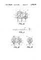
- FIG. 1is a cross-section through an apparatus of the invention
- FIG. 2is a cross-section on line A,A of FIG. 1;
- FIG. 3is the equivalent circuit of the apparatus shown in FIGS. 1 and 2;
- FIG. 4is a cross-section through a second apparatus of the invention.
- FIG. 5is a cross-section on line B,B of FIG. 4;
- FIG. 6is a plan view of a third apparatus of the invention.
- FIG. 8is an isometric drawing of a fourth apparatus of the invention.
- FIG. 9is the equivalent circuit of the apparatus shown in FIGS. 4 to 8;
- FIG. 10is a cross-section through a fourth apparatus of the invention.
- FIG. 11is the equivalent circuit of the apparatus shown in FIG. 10;
- FIG. 12is a cross-section through a device of the invention.
- FIG. 13is a cross-section on line D,D of FIG. 12;
- FIG. 15is a cross-section taken on line 2--2 of FIG. 1;
- FIG. 16is a diagram of a circuit including the device of FIGS. 14 and 15, a power source and a load.
- the second electrical componentcan be one which is specially designed for the particular performance characteristic required; for example, it can be composed of a ZTC conductive polymer.
- a particular advantage of this embodimentis that it can make use of standard commercially available electrical components as the second electrical component, or at least can make use of standard production techniques to produce suitable second electrical components.
- a component which has a recognized utility as part of a circuiteg. a voltage-dependent resistor (VDR) such as a varistor, a transistor, or another electronic component or a resistor whose resistance is comparatively independent of voltage.
- VDRvoltage-dependent resistor
- the second componentcan, for example, be a resistor which is a thick film resistor, a thin film resistor, a metallic film resistor, a carbon resistor, a metal wire, or a conductive polymer resistor formed by, for example, melt-shaping (including melt-extrusion, transfer molding and injection molding), solution-shaping (including printing and casting), sintering or any other suitable technique.
- the resistance of resistors produced by some of these techniquescan be changed by laser-trimming techniques.
- the resistance of the resistor at 23° C.is preferably at least 2 times, particularly at least 5 times, especially at least 10 times or even higher, eg. at least 20 times, the resistance at 23° C. of the PTC element.
- the resistance of the resistorpreferably does not increase substantially with temperature.
- the preferred total resistance at 23° C. of the first and second components togetherwill depend on the end use, and may be for example 3 to 2000 ohms, eg. 5 to 1500 ohms, but is usually 5 to 200 ohms, with the resistance of the PTC element being for example 1 to 100 ohms, usually 1 to 5 ohms.
- the leads which are secured to the second electrical componentcan function not only to connect the component to the circuit and to the first component, but can also be used to provide the electrodes of the first component.
- one of the leadscan be wrapped around an insulating member which surrounds the first component, and the PTC polymer can be molded around the wrapped product.
- one or both of the leadscan be bent into a suitable configuration around, but not touching, an insulating member which surrounds the first component, and the PTC polymer can be molded around the product.
- Suitable PTC conductive polymers for use in this inventionare disclosed in the prior art, eg. the documents incorporated by reference herein.
- the conductive polymershould have a resistivity which does not decrease in the temperature range T s to (T s +20)° C., preferably T s to (T s +40)° C., particularly T s to (T s +75)° C.
- the insulating element which lies between the first and second componentsis subject to substantial thermomechanical stress and should be selected accordingly.
- the insulating elementcomprises a metal surrounded by an insulating material, eg. anodized aluminum, in order to improve heat transfer from the second component to the PTC element; such an insulating element can be shaped so that it extends into the PTC element and thus delivers heat to a desired location for the hot zone between the electrodes.
- an insulating element of this kindis particularly valuable when the second component is in the form of a disc or other shape which cannot easily be fitted within the PTC element.
- the first and second electrical componentsare preferably arranged so that the thermal gradient induced in the PTC element is at right angles to the direction of current flow in the PTC element. This is important because the heat flow can otherwise encourage formation of the hot zone adjacent one of the electrodes, which is undesirable.
- the second electrical componentlies in a cavity in the PTC element between the electrodes, the desired result is usually easy to obtain.
- the first electrical componentpreferably comprises the novel combination of interdigitated electrodes positioned on a surface of a laminar PTC element, as described in detail in the parent application Ser. No. 628,945 incorporated by reference herein.
- Such a first electrical componentcan also be wrapped around a cylindrical second component, eg. a carbon resistor.
- the PTC and ZTC conductive polymer elementsare in direct contact with each other.
- the hot zoneforms at the interface between the PTC and ZTC elements, but in the devices of the present invention the elements are arranged so that the hot zone is confined to that part of the interface which is completely surrounded by the PTC and ZTC elements. It had not previously been realized that this was important because the presence of air at the hot zone increases the probability of breakdown.
- each of the electrodesis in the form of a columnar member (eg. a wire) having an enlarged head (eg. a disc or a sphere or a loop in the member) to reduce the current density on the electrode.
- the enlarged head of at least one of the electrodesis embedded in a ZTC element which is substantially surrounded by the PTC element.
- this aspect of the inventioncan be part of a larger device which does not meet the definition given above.
- this aspect of the inventionincludes for example a device which comprises (1) a laminar element as defined above and (2) electrodes which in one or more areas are as defined above in one or more areas fail to meet the definition given above, e.g. because the electrodes are too far apart.
- the laminar elementis composed of a PTC conductive polymer composition.
- PTC conductive polymer compositionMany such compositions are described in the various patents, patent applications and publications referred to above and incorporated by reference herein.
- Preferred compositionscomprise carbon black, or a mixture of carbon black and graphite, as the conductive filler.
- the compositioncan also contain a non-conductive filler, which may be reinforcing or non-reinforcing, and/or a filler exhibiting non-linear properties.
- One or more of the fillerscan be selected to have a high thermal conductivity.
- the polymerpreferably comprises at least one thermoplastic crystalline polymer.
- Particularly useful polymersare olefin polymers, incuding homopolymers, particularly polyethylene; copolymers of two or more olefins; and copolymers of one or more olefins, e.g. ethylene or propylene, with one or more olefinically unsaturated comonomers, preferably polar comonomers, e.g. vinyl acetate, acrylic acid methyl acrylate and ethyl acrylate.
- fluoropolymerswhich may be olefin polymers
- polyvinylidene fluoride and copolymers of ethylene with tetrafluoroethylene and/or a perfluoroalkoxy comonomercan be used, including mixtures of thermoplastic and amorphous, e.g. elastomeric, polymers.
- the conductive polymercan be cross-linked, preferably by irradiation, after it has been shaped, or while it is being shaped, into the laminar element.
- the preferred resistivity of the conductive polymer at room temperaturewill depend upon the desired characteristics of the device, but will generally be in the range from 0.5 to 100,000 ohm.cm, preferably 1.0 to 100 ohm.cm.
- the resistance of the device at 23° C.is preferably from 1 to 1,000, especially from 2 to 100 ohms.
- the polymeris preferably melt-shaped, with melt-extrusion usually being preferred.
- the electrodesare preferably arranged so that current flow between them predominantly follows (e.g. is at an angle of not more than 30°, preferably not more than 15°, to) the direction of orientation (which, in the case of melt-extrusion, is the direction of extrusion).
- the laminar elementcan be very thin, but generally has a thickness of at least 0.002 inch, preferably at least 0.008 inch, particularly at least 0.01 inch. There is no upper limit on the thickness of the laminar element, but the thickness of the element is generally not more than 0.25 inch, and when the electrodes are applied to a surface of the element, is usually not more 0.1 inch, preferably not more than 0.05 inch, particularly not more than 0.025 inch.
- the electrodescan be secured in or on the laminar element in any convenient way, for example by means of pre-shaped foil electrodes, by printing a conductive ink onto the laminar element to form the electrodes, through the use of polymer thick film technology, or by sputtering, or by a process comprising an etching step.
- the electrodescan also be formed on a surface of an insulating laminar element, for example by the techniques noted above or by etching, and the conductive polymer can then be secured to the electrodes and the insulating laminar element, for example by laminating a pre-formed film of the conductive polymer to the insulating element.
- Suitable materials for the electrodesinclude metals and metal alloys, for example silver, copper, ruthenium, gold and nickel. Electrodes comprising graphite can also be used.
- the ratio of the average width of the electrodes, measured parallel to the faces of the laminar element, to the average distance between adjacent electrodes between which current passes, measured parallel to the faces of the laminar element,is at least 0.1:1, preferably at least 0.25:1, particularly at least 0.4:1, especially at least 0.5:1, with a preferred upper limit of less than 10:1, particularly less than 5:1, especially less than 3:1.
- the electrodescan be equally spaced from each other. However, variation of the distance between the electrodes is possible, and can produce valuable effects on the dynamics of the tripping of the device.
- the electrodesare so positioned and dimensioned that, at all points, the distance between adjacent electrodes between which current passes, measured parallel to the faces of the laminar element, is not more than ten times, preferably not more than six times, especially not more than three times the average distance between adjacent electrodes between which current passes, measured parallel to the faces of the laminar element.
- the total surface area of the electrodes, viewed at right angles to the laminar element, to the surface area of one of the faces of the laminar elementis preferably at least 0.1:1, particularly at least 0.25:1, especially at least 0.5:1.
- Preferred patterns for the electrodesinclude interdigitating comb-like patterns of opposite polarities; a central backbone of one polarity with two comb-like patterns which interdigitate with the fingers on opposite sides of the backbone and which both have a polarity opposite to the central backbone; and a central backbone with two comb-like patterns which interdigitate with the fingers on opposite sides of the backbone and which are of opposite polarity to each other, with the backbone being at an intermediate voltage when a DC power supply is used or providing a neutral (which may be a floating neutral) when an AC power supply is used.
- FIGS. 1 and 2one lead of each of two carbon resistors is wrapped around the insulating container of the resistor to provide one of the electrodes which contact the PTC element.
- FIGS. 4 and 5each of leads from a carbon resistor has been modified into a desired electrode shape and then embedded in the PTC element; the dotted lines in FIG. 4 show where one of the leads was severed, after molding was complete, to provide the desired configuration.
- FIG. 6 and 7show a first component which comprises interdigitated electrodes secured to a laminar PTC element and which is secured to a flat resistor.
- FIG. 8shows a similar first component wrapped around a cylindrical resistor.
- FIG. 10shows an apparatus which comprises two second components, one a resistor, the other a VDR.
- FIGS. 12 and 13illustrate the second embodiment of the invention and show electrodes 2 and 3 with enlarged heads which are embedded in ZTC conductive polymer elements 8 which are in turn embedded in a PTC conductive polymer element 1.
- the PTC conductive polymer elementis preferably shaped with a construction 11 to promote formation of the hot zone at a location midway between the electrodes.
- the devicewhich has a resistance at room temperature of about 1 ohm, was tested by connecting it in series with a 80 volt AC power source and a load resistance of about 25 ohms, which resulted in an initial current of about 3.0 amp passing through the device. In about 5 seconds, the resistance of the device rose to about 210 ohms, thus reducing the current to about 0.380 amps.
Landscapes
- Engineering & Computer Science (AREA)
- Microelectronics & Electronic Packaging (AREA)
- Physics & Mathematics (AREA)
- Electromagnetism (AREA)
- Chemical & Material Sciences (AREA)
- Dispersion Chemistry (AREA)
- Ceramic Engineering (AREA)
- Thermistors And Varistors (AREA)
Abstract
Description
Claims (27)
Priority Applications (1)
| Application Number | Priority Date | Filing Date | Title |
|---|---|---|---|
| US07/150,005US4780598A (en) | 1984-07-10 | 1988-02-04 | Composite circuit protection devices |
Applications Claiming Priority (2)
| Application Number | Priority Date | Filing Date | Title |
|---|---|---|---|
| US62894584A | 1984-07-10 | 1984-07-10 | |
| US07/150,005US4780598A (en) | 1984-07-10 | 1988-02-04 | Composite circuit protection devices |
Related Parent Applications (1)
| Application Number | Title | Priority Date | Filing Date |
|---|---|---|---|
| US06754807Continuation | 1985-07-12 |
Publications (1)
| Publication Number | Publication Date |
|---|---|
| US4780598Atrue US4780598A (en) | 1988-10-25 |
Family
ID=26847234
Family Applications (1)
| Application Number | Title | Priority Date | Filing Date |
|---|---|---|---|
| US07/150,005Expired - LifetimeUS4780598A (en) | 1984-07-10 | 1988-02-04 | Composite circuit protection devices |
Country Status (1)
| Country | Link |
|---|---|
| US (1) | US4780598A (en) |
Cited By (108)
| Publication number | Priority date | Publication date | Assignee | Title |
|---|---|---|---|---|
| US5089801A (en)* | 1990-09-28 | 1992-02-18 | Raychem Corporation | Self-regulating ptc devices having shaped laminar conductive terminals |
| DE4310072A1 (en)* | 1992-03-31 | 1993-10-07 | Valeo Vision | Electrical accessory plug connected to cigarette lighter ignition - has first and second contact parts with second cooperative with ignition bimetallic element |
| US5293297A (en)* | 1991-12-30 | 1994-03-08 | Motorola, Inc. | Thermally regulated safety device for portable energy units |
| US5303115A (en)* | 1992-01-27 | 1994-04-12 | Raychem Corporation | PTC circuit protection device comprising mechanical stress riser |
| US5313184A (en)* | 1991-12-21 | 1994-05-17 | Asea Brown Boveri Ltd. | Resistor with PTC behavior |
| US5363084A (en)* | 1993-02-26 | 1994-11-08 | Lake Shore Cryotronics, Inc. | Film resistors having trimmable electrodes |
| US5369247A (en)* | 1992-10-29 | 1994-11-29 | Doljack; Frank A. | Self-regulating electrical heater system and method |
| US5378407A (en)* | 1992-06-05 | 1995-01-03 | Raychem Corporation | Conductive polymer composition |
| US5436609A (en)* | 1990-09-28 | 1995-07-25 | Raychem Corporation | Electrical device |
| US5451919A (en)* | 1993-06-29 | 1995-09-19 | Raychem Corporation | Electrical device comprising a conductive polymer composition |
| US5471035A (en)* | 1993-10-22 | 1995-11-28 | Eaton Corporation | Sandwich construction for current limiting positive temperature coefficient protective device |
| US5473495A (en)* | 1993-12-03 | 1995-12-05 | Eaton Corporation | Combination load controller |
| US5493101A (en)* | 1993-12-15 | 1996-02-20 | Eaton Corporation | Positive temperature coefficient transition sensor |
| US5530613A (en)* | 1994-06-01 | 1996-06-25 | Eaton Corporation | Current limiting circuit controller |
| US5610931A (en)* | 1995-12-11 | 1997-03-11 | Lucent Technologies Inc. | Transient protection circuit |
| US5663702A (en)* | 1995-06-07 | 1997-09-02 | Littelfuse, Inc. | PTC electrical device having fuse link in series and metallized ceramic electrodes |
| US5666254A (en)* | 1995-09-14 | 1997-09-09 | Raychem Corporation | Voltage sensing overcurrent protection circuit |
| US5689395A (en)* | 1995-09-14 | 1997-11-18 | Raychem Corporation | Overcurrent protection circuit |
| US5734314A (en)* | 1996-08-08 | 1998-03-31 | Cts Corporation | Low resistance paints for surge applications using nickel-chromium alloy blended with additional alloys |
| US5737160A (en)* | 1995-09-14 | 1998-04-07 | Raychem Corporation | Electrical switches comprising arrangement of mechanical switches and PCT device |
| US5814791A (en)* | 1996-06-18 | 1998-09-29 | Littelfuse, Inc. | Electrical apparatus with a variable circuit protection device |
| US5841111A (en)* | 1996-12-19 | 1998-11-24 | Eaton Corporation | Low resistance electrical interface for current limiting polymers by plasma processing |
| EP0798750A3 (en)* | 1996-03-30 | 1998-12-02 | Abb Research Ltd. | Current limiting resistor with PTC-behaviour |
| US5852397A (en)* | 1992-07-09 | 1998-12-22 | Raychem Corporation | Electrical devices |
| US5858533A (en)* | 1993-10-15 | 1999-01-12 | Abb Research Ltd. | Composite material |
| US5864458A (en)* | 1995-09-14 | 1999-01-26 | Raychem Corporation | Overcurrent protection circuits comprising combinations of PTC devices and switches |
| US5903240A (en)* | 1996-02-13 | 1999-05-11 | Murata Mfg. Co. Ltd | Surface mounting antenna and communication apparatus using the same antenna |
| US5907272A (en)* | 1996-01-22 | 1999-05-25 | Littelfuse, Inc. | Surface mountable electrical device comprising a PTC element and a fusible link |
| EP0908902A3 (en)* | 1997-10-07 | 1999-09-22 | Sony Chemicals Corporation | PTC-element, protective device and electric circuit board |
| US5977862A (en)* | 1996-04-26 | 1999-11-02 | Gec Alsthom T & D Sa | Polymer high voltage current limiters packaged in series |
| DE19842008A1 (en)* | 1998-09-15 | 2000-03-16 | Moeller Gmbh | Contact structure, for PTC type conductive polymers used in electrical switching and protection devices, comprises coated copper contact electrodes heat treated to achieve low elasticity modulus |
| DE19842006A1 (en)* | 1998-09-15 | 2000-03-16 | Moeller Gmbh | Contact structure, for PTC type conductive polymers used in electrical switching and protection devices, comprises a polymer sheet sandwiched between highly flexible metal contact electrodes |
| US6072679A (en)* | 1998-02-06 | 2000-06-06 | Myong; Inho | Electric protection systems including PTC and relay-contact-protecting RC-diode network |
| US6078160A (en)* | 1997-10-31 | 2000-06-20 | Cilluffo; Anthony | Bidirectional DC motor control circuit including overcurrent protection PTC device and relay |
| US6128168A (en)* | 1998-01-14 | 2000-10-03 | General Electric Company | Circuit breaker with improved arc interruption function |
| US6144540A (en)* | 1999-03-09 | 2000-11-07 | General Electric Company | Current suppressing circuit breaker unit for inductive motor protection |
| US6157528A (en)* | 1999-01-28 | 2000-12-05 | X2Y Attenuators, L.L.C. | Polymer fuse and filter apparatus |
| US6157286A (en)* | 1999-04-05 | 2000-12-05 | General Electric Company | High voltage current limiting device |
| US6215636B1 (en)* | 1997-03-24 | 2001-04-10 | Siemens Automotive, S.A. | Device for supplying electric power to several parallel-fed circuits, and method for making same |
| US6225610B1 (en) | 1993-08-23 | 2001-05-01 | Malcolm R. Walsh | Use of PTC devices to protect insulated wires in electrical harnesses |
| US6252493B1 (en)* | 2000-10-27 | 2001-06-26 | The Wiremold Company Brooks Electronics Division | High current varistor |
| US6292088B1 (en) | 1994-05-16 | 2001-09-18 | Tyco Electronics Corporation | PTC electrical devices for installation on printed circuit boards |
| US6300859B1 (en)* | 1999-08-24 | 2001-10-09 | Tyco Electronics Corporation | Circuit protection devices |
| US6349022B1 (en) | 1998-09-18 | 2002-02-19 | Tyco Electronics Corporation | Latching protection circuit |
| US6356424B1 (en) | 1998-02-06 | 2002-03-12 | Tyco Electronics Corporation | Electrical protection systems |
| US6392528B1 (en)* | 1997-06-04 | 2002-05-21 | Tyco Electronics Corporation | Circuit protection devices |
| US6421216B1 (en) | 1996-07-16 | 2002-07-16 | Ewd, Llc | Resetable overcurrent protection arrangement |
| US20020158515A1 (en)* | 1997-04-08 | 2002-10-31 | Anthony Anthony A. | Offset pathway arrangements for energy conditioning |
| US20020162214A1 (en)* | 1999-09-14 | 2002-11-07 | Scott Hetherton | Electrical devices and process for making such devices |
| US6483685B1 (en)* | 1999-12-23 | 2002-11-19 | Mcgraw Edison Company | Compliant joint between electrical components |
| US6489879B1 (en)* | 1999-12-10 | 2002-12-03 | National Semiconductor Corporation | PTC fuse including external heat source |
| US6519129B1 (en)* | 1999-11-02 | 2003-02-11 | Cooper Industries, Inc. | Surge arrester module with bonded component stack |
| US20030029635A1 (en)* | 1997-04-08 | 2003-02-13 | Anthony Anthony A. | Pathway arrangement |
| US20030029632A1 (en)* | 1997-04-08 | 2003-02-13 | Anthony Anthony A. | Arrangement for energy conditioning |
| US20030067730A1 (en)* | 1997-04-08 | 2003-04-10 | Anthony Anthony A. | Universial energy conditioning interposer with circuit architecture |
| US20030090855A1 (en)* | 2001-11-12 | 2003-05-15 | Chu Edward Fu-Hua | Over-current protection device and apparatus thereof |
| US20030154591A1 (en)* | 2000-06-19 | 2003-08-21 | Ralf Strumpler | Method of producing a ptc-resistor device |
| US20030161086A1 (en)* | 2000-07-18 | 2003-08-28 | X2Y Attenuators, Llc | Paired multi-layered dielectric independent passive component architecture resulting in differential and common mode filtering with surge protection in one integrated package |
| US6614640B2 (en)* | 2000-01-10 | 2003-09-02 | Abb Schweiz Ag | Surge arrester |
| US20030202312A1 (en)* | 2000-04-28 | 2003-10-30 | Anthony Anthony A. | Predetermined symmetrically balanced amalgam with complementary paired portions comprising shielding electrodes and shielded electrodes and other predetermined element portions for symmetrically balanced and complementary energy portion conditioning |
| US6640420B1 (en) | 1999-09-14 | 2003-11-04 | Tyco Electronics Corporation | Process for manufacturing a composite polymeric circuit protection device |
| US6661633B1 (en)* | 1999-08-04 | 2003-12-09 | Sony Chemicals Corp. | Protective element |
| US20030231456A1 (en)* | 2000-03-22 | 2003-12-18 | Anthony Anthony | Energy conditioning structure |
| US20030231451A1 (en)* | 1997-04-08 | 2003-12-18 | Anthony Anthony A. | Component carrier |
| US20040004802A1 (en)* | 2000-08-15 | 2004-01-08 | Anthony Anthony A. | Electrode arrangement for circuit energy conditioning |
| US20040008466A1 (en)* | 1997-04-08 | 2004-01-15 | Anthony Anthony A. | Multi-functional energy conditioner |
| US20040032304A1 (en)* | 1998-04-07 | 2004-02-19 | Anthony Anthony A. | Energy conditioning circuit assembly |
| US20040042141A1 (en)* | 2002-06-25 | 2004-03-04 | Adrian Mikolajczak | Integrated device providing overcurrent and overvoltage protection and common-mode filtering to data bus interface |
| US20040105205A1 (en)* | 2000-10-17 | 2004-06-03 | Anthony William M. | Energy pathway arrangement |
| US20040114286A1 (en)* | 2002-12-13 | 2004-06-17 | Sullivan Steven K. | Solid state motor protector |
| US20040124949A1 (en)* | 1998-04-07 | 2004-07-01 | Anthony Anthony | Component carrier |
| US20040130840A1 (en)* | 2000-12-15 | 2004-07-08 | Anthony William M. | Energy pathway arrangements for energy conditioning |
| US20040246645A1 (en)* | 2003-06-04 | 2004-12-09 | Bel Fuse Incorporated | Telecom circuit protection apparatus |
| US6873513B2 (en) | 1997-04-08 | 2005-03-29 | X2Y Attenuators, Llc | Paired multi-layered dielectric independent passive component architecture resulting in differential and common mode filtering with surge protection in one integrated package |
| US20050094347A1 (en)* | 2003-11-05 | 2005-05-05 | Zack Lin | Over-current protection device and manufacturing method thereof |
| US20050110607A1 (en)* | 2003-11-20 | 2005-05-26 | Babic Tomas I. | Mechanical reinforcement structure for fuses |
| US20050130491A1 (en)* | 2003-12-12 | 2005-06-16 | Chirkes Norberto J. | Automobile compact fuse holder |
| US20050160587A1 (en)* | 2004-01-23 | 2005-07-28 | Ramarge Michael M. | Manufacturing process for surge arrester module using pre-impregnated composite |
| US20050207084A1 (en)* | 2004-03-16 | 2005-09-22 | Ramarge Michael M | Station class surge arrester |
| US6954346B2 (en) | 1997-04-08 | 2005-10-11 | Xzy Attenuators, Llc | Filter assembly |
| US20050243495A1 (en)* | 2004-04-29 | 2005-11-03 | Ramarge Michael M | Liquid immersed surge arrester |
| US20060152878A1 (en)* | 2001-08-29 | 2006-07-13 | Ramarge Michael M | Mechanical reinforcement to improve high current, short duration withstand of a monolithic disk or bonded disk stack |
| US20060152330A1 (en)* | 2005-01-12 | 2006-07-13 | Jong-Sung Kang | PTC current limiting device having molding part made of insulating material |
| US20060215342A1 (en)* | 2005-03-28 | 2006-09-28 | Wayne Montoya | Surface mount multi-layer electrical circuit protection device with active element between PPTC layers |
| US7180718B2 (en) | 2003-01-31 | 2007-02-20 | X2Y Attenuators, Llc | Shielded energy conditioner |
| US7193831B2 (en) | 2000-10-17 | 2007-03-20 | X2Y Attenuators, Llc | Energy pathway arrangement |
| US7205672B1 (en) | 2001-12-05 | 2007-04-17 | National Semiconductor Corporation | Flip chip mounted to thermal sensing element through the back side of the chip |
| US7224564B2 (en) | 2000-10-17 | 2007-05-29 | X2Y Attenuators, Llc | Amalgam of shielding and shielded energy pathways and other elements for single or multiple circuitries with common reference node |
| US20070236849A1 (en)* | 2006-04-06 | 2007-10-11 | Littelfuse, Inc. | Leadless integrated circuit protection device |
| US7301748B2 (en) | 1997-04-08 | 2007-11-27 | Anthony Anthony A | Universal energy conditioning interposer with circuit architecture |
| US7321485B2 (en) | 1997-04-08 | 2008-01-22 | X2Y Attenuators, Llc | Arrangement for energy conditioning |
| US7336468B2 (en) | 1997-04-08 | 2008-02-26 | X2Y Attenuators, Llc | Arrangement for energy conditioning |
| US7427816B2 (en) | 1998-04-07 | 2008-09-23 | X2Y Attenuators, Llc | Component carrier |
| US7440252B2 (en) | 2003-05-29 | 2008-10-21 | X2Y Attenuators, Llc | Connector related structures including an energy conditioner |
| US7586728B2 (en) | 2005-03-14 | 2009-09-08 | X2Y Attenuators, Llc | Conditioner with coplanar conductors |
| US20090236565A1 (en)* | 2007-09-28 | 2009-09-24 | Sabic Innovative Plastics Ip Bv | Thermoplastic composition with improved positive temperature coefficient behavior and method for making thereof |
| US7630188B2 (en) | 2005-03-01 | 2009-12-08 | X2Y Attenuators, Llc | Conditioner with coplanar conductors |
| US7660096B2 (en) | 2005-07-29 | 2010-02-09 | Tyco Electronics Corporation | Circuit protection device having thermally coupled MOV overvoltage element and PPTC overcurrent element |
| US7675729B2 (en) | 2003-12-22 | 2010-03-09 | X2Y Attenuators, Llc | Internally shielded energy conditioner |
| US7817397B2 (en) | 2005-03-01 | 2010-10-19 | X2Y Attenuators, Llc | Energy conditioner with tied through electrodes |
| US20100284115A1 (en)* | 2009-05-05 | 2010-11-11 | Interconnect Portfolio Llc | ESD Protection Utilizing Radiated Thermal Relief |
| US8026777B2 (en) | 2006-03-07 | 2011-09-27 | X2Y Attenuators, Llc | Energy conditioner structures |
| US20140110388A1 (en)* | 2012-10-23 | 2014-04-24 | Ford Global Technologies, Llc | Heated steering wheel |
| US9054094B2 (en) | 1997-04-08 | 2015-06-09 | X2Y Attenuators, Llc | Energy conditioning circuit arrangement for integrated circuit |
| US20170229272A1 (en)* | 2014-10-23 | 2017-08-10 | Sm Hi-Tech Co.,Ltd. | Smd micro mixed fuse having thermal fuse function and method for manufacturing the same |
| US11894166B2 (en) | 2022-01-05 | 2024-02-06 | Richards Mfg. Co., A New Jersey Limited Partnership | Manufacturing process for surge arrestor module using compaction bladder system |
| US12015375B2 (en) | 2014-09-09 | 2024-06-18 | Shoals Technologies Group, Llc | Lead assembly for connecting solar panel arrays to inverter |
| US12444522B2 (en) | 2023-08-08 | 2025-10-14 | Richards Mfg. Co. Sales, Llc | Manufacturing process for surge arrestor module using compaction bladder system |
Citations (29)
| Publication number | Priority date | Publication date | Assignee | Title |
|---|---|---|---|---|
| US3287684A (en)* | 1964-02-27 | 1966-11-22 | Motson Services Inc | Electrical heating device |
| US3861029A (en)* | 1972-09-08 | 1975-01-21 | Raychem Corp | Method of making heater cable |
| DE2434006A1 (en)* | 1974-07-15 | 1976-02-05 | Siemens Ag | Thermostat for heating system - has varistor in parallel with PTC resistor and ignition capacitor |
| US4034207A (en)* | 1976-01-23 | 1977-07-05 | Murata Manufacturing Co., Ltd. | Positive temperature coefficient semiconductor heating element |
| US4037082A (en)* | 1976-04-30 | 1977-07-19 | Murata Manufacturing Co., Ltd. | Positive temperature coefficient semiconductor heating device |
| US4051550A (en)* | 1974-11-29 | 1977-09-27 | Hitachi, Ltd. | Thick film integrated circuits |
| DE2644256A1 (en)* | 1976-09-28 | 1978-03-30 | Siemens Ag | Resistive system with voltage dependent resistors - uses PTC resistive material to compensate NTC of voltage dependent resistors |
| US4099216A (en)* | 1976-11-12 | 1978-07-04 | Westinghouse Electric Corp. | Fuseless intrinsic safety barrier |
| US4162395A (en)* | 1975-11-07 | 1979-07-24 | Murata Manufacturing Co., Ltd. | Heating unit for heating fluid |
| US4174511A (en)* | 1977-03-24 | 1979-11-13 | Robert Bosch Gmbh | Bimetal device with an electrical heating element |
| US4177446A (en)* | 1975-12-08 | 1979-12-04 | Raychem Corporation | Heating elements comprising conductive polymers capable of dimensional change |
| US4177785A (en)* | 1977-10-31 | 1979-12-11 | General Motors Corporation | Diesel engine glow plug energization control device |
| DE2825442A1 (en)* | 1978-06-09 | 1979-12-13 | Lauerer Friedrich | Faulty current protective circuit breaker - has varistors inside housing coupled to PTC resistors and has externally controllable connection to neutral conductor |
| US4237411A (en)* | 1977-10-29 | 1980-12-02 | Varta Batterie, A.G. | Charge maintenance and continuous charging for storage batteries |
| US4247441A (en)* | 1979-02-09 | 1981-01-27 | General Electric Company | Process for preparing a silicone molding composition |
| DE2946842A1 (en)* | 1979-11-20 | 1981-05-21 | Siemens AG, 1000 Berlin und 8000 München | Heating element with PTC honeycombed body - having specified current supply points allowing different powers to be obtained for same voltage input |
| EP0031283A2 (en)* | 1979-12-21 | 1981-07-01 | Lignes Telegraphiques Et Telephoniques L.T.T. | Protective circuit for a switching circuit |
| EP0038718A1 (en)* | 1980-04-21 | 1981-10-28 | RAYCHEM CORPORATION (a California corporation) | Conductive polymer compositions containing fillers |
| US4388607A (en)* | 1976-12-16 | 1983-06-14 | Raychem Corporation | Conductive polymer compositions, and to devices comprising such compositions |
| EP0087884A1 (en)* | 1982-02-17 | 1983-09-07 | RAYCHEM CORPORATION (a California corporation) | PTC circuit protection device |
| US4413174A (en)* | 1980-02-04 | 1983-11-01 | Texas Instruments Incorporated | Glow plug duty cycle modulating apparatus |
| US4413301A (en)* | 1980-04-21 | 1983-11-01 | Raychem Corporation | Circuit protection devices comprising PTC element |
| FR2528253A1 (en)* | 1982-06-04 | 1983-12-09 | Jaeger | Overvoltage protection circuit for electronic components - has zener diode and PTC resistor connected in series and in good thermal contact |
| US4426339A (en)* | 1976-12-13 | 1984-01-17 | Raychem Corporation | Method of making electrical devices comprising conductive polymer compositions |
| EP0098647A1 (en)* | 1982-07-02 | 1984-01-18 | Koninklijke Philips Electronics N.V. | Mains-voltage discrimination device |
| US4445026A (en)* | 1979-05-21 | 1984-04-24 | Raychem Corporation | Electrical devices comprising PTC conductive polymer elements |
| US4467310A (en)* | 1983-10-03 | 1984-08-21 | Northern Telecom Limited | Telephone subscriber line battery feed resistor arrangements |
| US4542365A (en)* | 1982-02-17 | 1985-09-17 | Raychem Corporation | PTC Circuit protection device |
| US4549161A (en)* | 1982-02-17 | 1985-10-22 | Raychem Corporation | PTC Circuit protection device |
- 1988
- 1988-02-04USUS07/150,005patent/US4780598A/ennot_activeExpired - Lifetime
Patent Citations (31)
| Publication number | Priority date | Publication date | Assignee | Title |
|---|---|---|---|---|
| US3287684A (en)* | 1964-02-27 | 1966-11-22 | Motson Services Inc | Electrical heating device |
| US3861029A (en)* | 1972-09-08 | 1975-01-21 | Raychem Corp | Method of making heater cable |
| DE2434006A1 (en)* | 1974-07-15 | 1976-02-05 | Siemens Ag | Thermostat for heating system - has varistor in parallel with PTC resistor and ignition capacitor |
| US4051550A (en)* | 1974-11-29 | 1977-09-27 | Hitachi, Ltd. | Thick film integrated circuits |
| US4162395A (en)* | 1975-11-07 | 1979-07-24 | Murata Manufacturing Co., Ltd. | Heating unit for heating fluid |
| US4177446A (en)* | 1975-12-08 | 1979-12-04 | Raychem Corporation | Heating elements comprising conductive polymers capable of dimensional change |
| US4034207A (en)* | 1976-01-23 | 1977-07-05 | Murata Manufacturing Co., Ltd. | Positive temperature coefficient semiconductor heating element |
| US4037082A (en)* | 1976-04-30 | 1977-07-19 | Murata Manufacturing Co., Ltd. | Positive temperature coefficient semiconductor heating device |
| DE2644256A1 (en)* | 1976-09-28 | 1978-03-30 | Siemens Ag | Resistive system with voltage dependent resistors - uses PTC resistive material to compensate NTC of voltage dependent resistors |
| US4099216A (en)* | 1976-11-12 | 1978-07-04 | Westinghouse Electric Corp. | Fuseless intrinsic safety barrier |
| US4426339B1 (en)* | 1976-12-13 | 1993-12-21 | Raychem Corp. | Method of making electrical devices comprising conductive polymer compositions |
| US4426339A (en)* | 1976-12-13 | 1984-01-17 | Raychem Corporation | Method of making electrical devices comprising conductive polymer compositions |
| US4388607A (en)* | 1976-12-16 | 1983-06-14 | Raychem Corporation | Conductive polymer compositions, and to devices comprising such compositions |
| US4174511A (en)* | 1977-03-24 | 1979-11-13 | Robert Bosch Gmbh | Bimetal device with an electrical heating element |
| US4237411A (en)* | 1977-10-29 | 1980-12-02 | Varta Batterie, A.G. | Charge maintenance and continuous charging for storage batteries |
| US4177785A (en)* | 1977-10-31 | 1979-12-11 | General Motors Corporation | Diesel engine glow plug energization control device |
| DE2825442A1 (en)* | 1978-06-09 | 1979-12-13 | Lauerer Friedrich | Faulty current protective circuit breaker - has varistors inside housing coupled to PTC resistors and has externally controllable connection to neutral conductor |
| US4247441A (en)* | 1979-02-09 | 1981-01-27 | General Electric Company | Process for preparing a silicone molding composition |
| US4445026A (en)* | 1979-05-21 | 1984-04-24 | Raychem Corporation | Electrical devices comprising PTC conductive polymer elements |
| DE2946842A1 (en)* | 1979-11-20 | 1981-05-21 | Siemens AG, 1000 Berlin und 8000 München | Heating element with PTC honeycombed body - having specified current supply points allowing different powers to be obtained for same voltage input |
| EP0031283A2 (en)* | 1979-12-21 | 1981-07-01 | Lignes Telegraphiques Et Telephoniques L.T.T. | Protective circuit for a switching circuit |
| US4413174A (en)* | 1980-02-04 | 1983-11-01 | Texas Instruments Incorporated | Glow plug duty cycle modulating apparatus |
| US4413301A (en)* | 1980-04-21 | 1983-11-01 | Raychem Corporation | Circuit protection devices comprising PTC element |
| EP0038718A1 (en)* | 1980-04-21 | 1981-10-28 | RAYCHEM CORPORATION (a California corporation) | Conductive polymer compositions containing fillers |
| US4481498A (en)* | 1982-02-17 | 1984-11-06 | Raychem Corporation | PTC Circuit protection device |
| US4542365A (en)* | 1982-02-17 | 1985-09-17 | Raychem Corporation | PTC Circuit protection device |
| US4549161A (en)* | 1982-02-17 | 1985-10-22 | Raychem Corporation | PTC Circuit protection device |
| EP0087884A1 (en)* | 1982-02-17 | 1983-09-07 | RAYCHEM CORPORATION (a California corporation) | PTC circuit protection device |
| FR2528253A1 (en)* | 1982-06-04 | 1983-12-09 | Jaeger | Overvoltage protection circuit for electronic components - has zener diode and PTC resistor connected in series and in good thermal contact |
| EP0098647A1 (en)* | 1982-07-02 | 1984-01-18 | Koninklijke Philips Electronics N.V. | Mains-voltage discrimination device |
| US4467310A (en)* | 1983-10-03 | 1984-08-21 | Northern Telecom Limited | Telephone subscriber line battery feed resistor arrangements |
Cited By (183)
| Publication number | Priority date | Publication date | Assignee | Title |
|---|---|---|---|---|
| US5089801A (en)* | 1990-09-28 | 1992-02-18 | Raychem Corporation | Self-regulating ptc devices having shaped laminar conductive terminals |
| US5436609A (en)* | 1990-09-28 | 1995-07-25 | Raychem Corporation | Electrical device |
| US5313184A (en)* | 1991-12-21 | 1994-05-17 | Asea Brown Boveri Ltd. | Resistor with PTC behavior |
| US5293297A (en)* | 1991-12-30 | 1994-03-08 | Motorola, Inc. | Thermally regulated safety device for portable energy units |
| US5303115A (en)* | 1992-01-27 | 1994-04-12 | Raychem Corporation | PTC circuit protection device comprising mechanical stress riser |
| DE4310072A1 (en)* | 1992-03-31 | 1993-10-07 | Valeo Vision | Electrical accessory plug connected to cigarette lighter ignition - has first and second contact parts with second cooperative with ignition bimetallic element |
| US5378407A (en)* | 1992-06-05 | 1995-01-03 | Raychem Corporation | Conductive polymer composition |
| US6651315B1 (en) | 1992-07-09 | 2003-11-25 | Tyco Electronics Corporation | Electrical devices |
| US5852397A (en)* | 1992-07-09 | 1998-12-22 | Raychem Corporation | Electrical devices |
| US7355504B2 (en) | 1992-07-09 | 2008-04-08 | Tyco Electronics Corporation | Electrical devices |
| US20040246092A1 (en)* | 1992-07-09 | 2004-12-09 | Graves Gregory A. | Electrical devices |
| US5369247A (en)* | 1992-10-29 | 1994-11-29 | Doljack; Frank A. | Self-regulating electrical heater system and method |
| US5363084A (en)* | 1993-02-26 | 1994-11-08 | Lake Shore Cryotronics, Inc. | Film resistors having trimmable electrodes |
| US5451919A (en)* | 1993-06-29 | 1995-09-19 | Raychem Corporation | Electrical device comprising a conductive polymer composition |
| US6225610B1 (en) | 1993-08-23 | 2001-05-01 | Malcolm R. Walsh | Use of PTC devices to protect insulated wires in electrical harnesses |
| US5858533A (en)* | 1993-10-15 | 1999-01-12 | Abb Research Ltd. | Composite material |
| US5471035A (en)* | 1993-10-22 | 1995-11-28 | Eaton Corporation | Sandwich construction for current limiting positive temperature coefficient protective device |
| US5473495A (en)* | 1993-12-03 | 1995-12-05 | Eaton Corporation | Combination load controller |
| US5493101A (en)* | 1993-12-15 | 1996-02-20 | Eaton Corporation | Positive temperature coefficient transition sensor |
| US6292088B1 (en) | 1994-05-16 | 2001-09-18 | Tyco Electronics Corporation | PTC electrical devices for installation on printed circuit boards |
| US5530613A (en)* | 1994-06-01 | 1996-06-25 | Eaton Corporation | Current limiting circuit controller |
| US5663702A (en)* | 1995-06-07 | 1997-09-02 | Littelfuse, Inc. | PTC electrical device having fuse link in series and metallized ceramic electrodes |
| US5737160A (en)* | 1995-09-14 | 1998-04-07 | Raychem Corporation | Electrical switches comprising arrangement of mechanical switches and PCT device |
| US5689395A (en)* | 1995-09-14 | 1997-11-18 | Raychem Corporation | Overcurrent protection circuit |
| US5666254A (en)* | 1995-09-14 | 1997-09-09 | Raychem Corporation | Voltage sensing overcurrent protection circuit |
| US5864458A (en)* | 1995-09-14 | 1999-01-26 | Raychem Corporation | Overcurrent protection circuits comprising combinations of PTC devices and switches |
| US5610931A (en)* | 1995-12-11 | 1997-03-11 | Lucent Technologies Inc. | Transient protection circuit |
| US5907272A (en)* | 1996-01-22 | 1999-05-25 | Littelfuse, Inc. | Surface mountable electrical device comprising a PTC element and a fusible link |
| US5903240A (en)* | 1996-02-13 | 1999-05-11 | Murata Mfg. Co. Ltd | Surface mounting antenna and communication apparatus using the same antenna |
| EP0798750A3 (en)* | 1996-03-30 | 1998-12-02 | Abb Research Ltd. | Current limiting resistor with PTC-behaviour |
| US5977862A (en)* | 1996-04-26 | 1999-11-02 | Gec Alsthom T & D Sa | Polymer high voltage current limiters packaged in series |
| US5814791A (en)* | 1996-06-18 | 1998-09-29 | Littelfuse, Inc. | Electrical apparatus with a variable circuit protection device |
| US6456476B1 (en) | 1996-07-16 | 2002-09-24 | Tyco Electronics Corporation | Circuit protection relay having bimetal wiper |
| US6421216B1 (en) | 1996-07-16 | 2002-07-16 | Ewd, Llc | Resetable overcurrent protection arrangement |
| US5734314A (en)* | 1996-08-08 | 1998-03-31 | Cts Corporation | Low resistance paints for surge applications using nickel-chromium alloy blended with additional alloys |
| US5841111A (en)* | 1996-12-19 | 1998-11-24 | Eaton Corporation | Low resistance electrical interface for current limiting polymers by plasma processing |
| US5886324A (en)* | 1996-12-19 | 1999-03-23 | Eaton Corporation | Electrode attachment for high power current limiting polymer devices |
| US5928547A (en)* | 1996-12-19 | 1999-07-27 | Eaton Corporation | High power current limiting polymer devices for circuit breaker applications |
| US6215636B1 (en)* | 1997-03-24 | 2001-04-10 | Siemens Automotive, S.A. | Device for supplying electric power to several parallel-fed circuits, and method for making same |
| US7768763B2 (en) | 1997-04-08 | 2010-08-03 | X2Y Attenuators, Llc | Arrangement for energy conditioning |
| US7321485B2 (en) | 1997-04-08 | 2008-01-22 | X2Y Attenuators, Llc | Arrangement for energy conditioning |
| US9054094B2 (en) | 1997-04-08 | 2015-06-09 | X2Y Attenuators, Llc | Energy conditioning circuit arrangement for integrated circuit |
| US9373592B2 (en) | 1997-04-08 | 2016-06-21 | X2Y Attenuators, Llc | Arrangement for energy conditioning |
| US9019679B2 (en) | 1997-04-08 | 2015-04-28 | X2Y Attenuators, Llc | Arrangement for energy conditioning |
| US6954346B2 (en) | 1997-04-08 | 2005-10-11 | Xzy Attenuators, Llc | Filter assembly |
| US6894884B2 (en) | 1997-04-08 | 2005-05-17 | Xzy Attenuators, Llc | Offset pathway arrangements for energy conditioning |
| US8587915B2 (en) | 1997-04-08 | 2013-11-19 | X2Y Attenuators, Llc | Arrangement for energy conditioning |
| US6873513B2 (en) | 1997-04-08 | 2005-03-29 | X2Y Attenuators, Llc | Paired multi-layered dielectric independent passive component architecture resulting in differential and common mode filtering with surge protection in one integrated package |
| US20060023385A9 (en)* | 1997-04-08 | 2006-02-02 | Anthony Anthony A | Multi-functional energy conditioner |
| US8023241B2 (en) | 1997-04-08 | 2011-09-20 | X2Y Attenuators, Llc | Arrangement for energy conditioning |
| US20050016761A9 (en)* | 1997-04-08 | 2005-01-27 | Anthony Anthony A. | Arrangement for energy conditioning |
| US7050284B2 (en) | 1997-04-08 | 2006-05-23 | X2Y Attenuators, Llc | Component carrier |
| US7106570B2 (en) | 1997-04-08 | 2006-09-12 | Xzy Altenuators, Llc | Pathway arrangement |
| US20020158515A1 (en)* | 1997-04-08 | 2002-10-31 | Anthony Anthony A. | Offset pathway arrangements for energy conditioning |
| US8018706B2 (en) | 1997-04-08 | 2011-09-13 | X2Y Attenuators, Llc | Arrangement for energy conditioning |
| US8004812B2 (en) | 1997-04-08 | 2011-08-23 | X2Y Attenuators, Llc | Energy conditioning circuit arrangement for integrated circuit |
| US7920367B2 (en) | 1997-04-08 | 2011-04-05 | X2Y Attenuators, Llc | Method for making arrangement for energy conditioning |
| US7916444B2 (en) | 1997-04-08 | 2011-03-29 | X2Y Attenuators, Llc | Arrangement for energy conditioning |
| US20030029635A1 (en)* | 1997-04-08 | 2003-02-13 | Anthony Anthony A. | Pathway arrangement |
| US20030029632A1 (en)* | 1997-04-08 | 2003-02-13 | Anthony Anthony A. | Arrangement for energy conditioning |
| US7110227B2 (en) | 1997-04-08 | 2006-09-19 | X2Y Attenuators, Llc | Universial energy conditioning interposer with circuit architecture |
| US20030067730A1 (en)* | 1997-04-08 | 2003-04-10 | Anthony Anthony A. | Universial energy conditioning interposer with circuit architecture |
| US7733621B2 (en) | 1997-04-08 | 2010-06-08 | X2Y Attenuators, Llc | Energy conditioning circuit arrangement for integrated circuit |
| US7688565B2 (en) | 1997-04-08 | 2010-03-30 | X2Y Attenuators, Llc | Arrangements for energy conditioning |
| US7609501B2 (en) | 1997-04-08 | 2009-10-27 | X2Y Attenuators, Llc | Manufacture including shield structure |
| US7609500B2 (en) | 1997-04-08 | 2009-10-27 | X2Y Attenuators, Llc | Universal energy conditioning interposer with circuit architecture |
| US7593208B2 (en) | 1997-04-08 | 2009-09-22 | X2Y Attenuators, Llc | Multi-functional energy conditioner |
| US7443647B2 (en) | 1997-04-08 | 2008-10-28 | X2Y Attenuators, Llc | Paired multi-layered dielectric independent passive component architecture resulting in differential and common mode filtering with surge protection in one integrated package |
| US20030206388A9 (en)* | 1997-04-08 | 2003-11-06 | Anthony Anthony A. | Universial energy conditioning interposer with circuit architecture |
| US7110235B2 (en) | 1997-04-08 | 2006-09-19 | Xzy Altenuators, Llc | Arrangement for energy conditioning |
| US7301748B2 (en) | 1997-04-08 | 2007-11-27 | Anthony Anthony A | Universal energy conditioning interposer with circuit architecture |
| US7423860B2 (en) | 1997-04-08 | 2008-09-09 | X2Y Attenuators, Llc | Multi-functional energy conditioner |
| US9036319B2 (en) | 1997-04-08 | 2015-05-19 | X2Y Attenuators, Llc | Arrangement for energy conditioning |
| US20030231451A1 (en)* | 1997-04-08 | 2003-12-18 | Anthony Anthony A. | Component carrier |
| US7336468B2 (en) | 1997-04-08 | 2008-02-26 | X2Y Attenuators, Llc | Arrangement for energy conditioning |
| US20040008466A1 (en)* | 1997-04-08 | 2004-01-15 | Anthony Anthony A. | Multi-functional energy conditioner |
| US6392528B1 (en)* | 1997-06-04 | 2002-05-21 | Tyco Electronics Corporation | Circuit protection devices |
| US6114672A (en)* | 1997-10-07 | 2000-09-05 | Sony Corporation | PTC-element, protective device and electric circuit board |
| EP0908902A3 (en)* | 1997-10-07 | 1999-09-22 | Sony Chemicals Corporation | PTC-element, protective device and electric circuit board |
| US6078160A (en)* | 1997-10-31 | 2000-06-20 | Cilluffo; Anthony | Bidirectional DC motor control circuit including overcurrent protection PTC device and relay |
| US6128168A (en)* | 1998-01-14 | 2000-10-03 | General Electric Company | Circuit breaker with improved arc interruption function |
| US6356424B1 (en) | 1998-02-06 | 2002-03-12 | Tyco Electronics Corporation | Electrical protection systems |
| US6072679A (en)* | 1998-02-06 | 2000-06-06 | Myong; Inho | Electric protection systems including PTC and relay-contact-protecting RC-diode network |
| US7141899B2 (en) | 1998-04-07 | 2006-11-28 | X2Y Attenuators, Llc | Component carrier |
| US7427816B2 (en) | 1998-04-07 | 2008-09-23 | X2Y Attenuators, Llc | Component carrier |
| US20040124949A1 (en)* | 1998-04-07 | 2004-07-01 | Anthony Anthony | Component carrier |
| US20040032304A1 (en)* | 1998-04-07 | 2004-02-19 | Anthony Anthony A. | Energy conditioning circuit assembly |
| US7042303B2 (en) | 1998-04-07 | 2006-05-09 | X2Y Attenuators, Llc | Energy conditioning circuit assembly |
| DE19842008A1 (en)* | 1998-09-15 | 2000-03-16 | Moeller Gmbh | Contact structure, for PTC type conductive polymers used in electrical switching and protection devices, comprises coated copper contact electrodes heat treated to achieve low elasticity modulus |
| DE19842006A1 (en)* | 1998-09-15 | 2000-03-16 | Moeller Gmbh | Contact structure, for PTC type conductive polymers used in electrical switching and protection devices, comprises a polymer sheet sandwiched between highly flexible metal contact electrodes |
| US6349022B1 (en) | 1998-09-18 | 2002-02-19 | Tyco Electronics Corporation | Latching protection circuit |
| US6282074B1 (en) | 1999-01-28 | 2001-08-28 | X2Y Attenuators, L.L.C. | Polymer fuse and filter apparatus |
| US6522516B2 (en) | 1999-01-28 | 2003-02-18 | X2Y Attenuators, Llc | Polymer fuse and filter apparatus |
| US6157528A (en)* | 1999-01-28 | 2000-12-05 | X2Y Attenuators, L.L.C. | Polymer fuse and filter apparatus |
| US20030210125A1 (en)* | 1999-01-28 | 2003-11-13 | X2Y Attenuators, Llc | Polymer fuse and filter apparatus |
| US6806806B2 (en)* | 1999-01-28 | 2004-10-19 | X2Y Attenuators, Llc | Polymer fuse and filter apparatus |
| US6388856B1 (en) | 1999-01-28 | 2002-05-14 | X2Y Attenuators, Llc | Polymer fuse and filter apparatus |
| US6144540A (en)* | 1999-03-09 | 2000-11-07 | General Electric Company | Current suppressing circuit breaker unit for inductive motor protection |
| US6157286A (en)* | 1999-04-05 | 2000-12-05 | General Electric Company | High voltage current limiting device |
| US6661633B1 (en)* | 1999-08-04 | 2003-12-09 | Sony Chemicals Corp. | Protective element |
| US6300859B1 (en)* | 1999-08-24 | 2001-10-09 | Tyco Electronics Corporation | Circuit protection devices |
| US6640420B1 (en) | 1999-09-14 | 2003-11-04 | Tyco Electronics Corporation | Process for manufacturing a composite polymeric circuit protection device |
| US6854176B2 (en)* | 1999-09-14 | 2005-02-15 | Tyco Electronics Corporation | Process for manufacturing a composite polymeric circuit protection device |
| US7343671B2 (en) | 1999-09-14 | 2008-03-18 | Tyco Electronics Corporation | Process for manufacturing a composite polymeric circuit protection device |
| US20040090304A1 (en)* | 1999-09-14 | 2004-05-13 | Scott Hetherton | Electrical devices and process for making such devices |
| US20020162214A1 (en)* | 1999-09-14 | 2002-11-07 | Scott Hetherton | Electrical devices and process for making such devices |
| US6519129B1 (en)* | 1999-11-02 | 2003-02-11 | Cooper Industries, Inc. | Surge arrester module with bonded component stack |
| US6847514B2 (en) | 1999-11-02 | 2005-01-25 | Cooper Industries, Inc. | Surge arrester module with bonded component stack |
| US6489879B1 (en)* | 1999-12-10 | 2002-12-03 | National Semiconductor Corporation | PTC fuse including external heat source |
| US6483685B1 (en)* | 1999-12-23 | 2002-11-19 | Mcgraw Edison Company | Compliant joint between electrical components |
| US6614640B2 (en)* | 2000-01-10 | 2003-09-02 | Abb Schweiz Ag | Surge arrester |
| US20030231456A1 (en)* | 2000-03-22 | 2003-12-18 | Anthony Anthony | Energy conditioning structure |
| US7042703B2 (en) | 2000-03-22 | 2006-05-09 | X2Y Attenuators, Llc | Energy conditioning structure |
| US7113383B2 (en) | 2000-04-28 | 2006-09-26 | X2Y Attenuators, Llc | Predetermined symmetrically balanced amalgam with complementary paired portions comprising shielding electrodes and shielded electrodes and other predetermined element portions for symmetrically balanced and complementary energy portion conditioning |
| US20030202312A1 (en)* | 2000-04-28 | 2003-10-30 | Anthony Anthony A. | Predetermined symmetrically balanced amalgam with complementary paired portions comprising shielding electrodes and shielded electrodes and other predetermined element portions for symmetrically balanced and complementary energy portion conditioning |
| US20030154591A1 (en)* | 2000-06-19 | 2003-08-21 | Ralf Strumpler | Method of producing a ptc-resistor device |
| US6932928B2 (en)* | 2000-06-19 | 2005-08-23 | Abb Research Ltd. | Method of producing a PTC-resistor device |
| US20030161086A1 (en)* | 2000-07-18 | 2003-08-28 | X2Y Attenuators, Llc | Paired multi-layered dielectric independent passive component architecture resulting in differential and common mode filtering with surge protection in one integrated package |
| US7262949B2 (en) | 2000-08-15 | 2007-08-28 | X2Y Attenuators, Llc | Electrode arrangement for circuit energy conditioning |
| US20040004802A1 (en)* | 2000-08-15 | 2004-01-08 | Anthony Anthony A. | Electrode arrangement for circuit energy conditioning |
| US20040105205A1 (en)* | 2000-10-17 | 2004-06-03 | Anthony William M. | Energy pathway arrangement |
| US7224564B2 (en) | 2000-10-17 | 2007-05-29 | X2Y Attenuators, Llc | Amalgam of shielding and shielded energy pathways and other elements for single or multiple circuitries with common reference node |
| US7336467B2 (en) | 2000-10-17 | 2008-02-26 | X2Y Attenuators, Llc | Energy pathway arrangement |
| US7433168B2 (en) | 2000-10-17 | 2008-10-07 | X2Y Attenuators, Llc | Amalgam of shielding and shielded energy pathways and other elements for single or multiple circuitries with common reference node |
| US7428134B2 (en) | 2000-10-17 | 2008-09-23 | X2Y Attenuators, Llc | Energy pathway arrangements for energy conditioning |
| US7193831B2 (en) | 2000-10-17 | 2007-03-20 | X2Y Attenuators, Llc | Energy pathway arrangement |
| US6252493B1 (en)* | 2000-10-27 | 2001-06-26 | The Wiremold Company Brooks Electronics Division | High current varistor |
| US20040130840A1 (en)* | 2000-12-15 | 2004-07-08 | Anthony William M. | Energy pathway arrangements for energy conditioning |
| US7274549B2 (en) | 2000-12-15 | 2007-09-25 | X2Y Attenuators, Llc | Energy pathway arrangements for energy conditioning |
| US20060152878A1 (en)* | 2001-08-29 | 2006-07-13 | Ramarge Michael M | Mechanical reinforcement to improve high current, short duration withstand of a monolithic disk or bonded disk stack |
| US20030090855A1 (en)* | 2001-11-12 | 2003-05-15 | Chu Edward Fu-Hua | Over-current protection device and apparatus thereof |
| US7205672B1 (en) | 2001-12-05 | 2007-04-17 | National Semiconductor Corporation | Flip chip mounted to thermal sensing element through the back side of the chip |
| CN1625788B (en)* | 2001-12-12 | 2010-06-09 | 泰科电子有限公司 | Electrical devices and process for making such devices |
| US20040042141A1 (en)* | 2002-06-25 | 2004-03-04 | Adrian Mikolajczak | Integrated device providing overcurrent and overvoltage protection and common-mode filtering to data bus interface |
| US6937454B2 (en) | 2002-06-25 | 2005-08-30 | Tyco Electronics Corporation | Integrated device providing overcurrent and overvoltage protection and common-mode filtering to data bus interface |
| US20040114286A1 (en)* | 2002-12-13 | 2004-06-17 | Sullivan Steven K. | Solid state motor protector |
| US7038896B2 (en)* | 2002-12-13 | 2006-05-02 | Texas Instruments Incorporated | Solid state motor protector |
| US7180718B2 (en) | 2003-01-31 | 2007-02-20 | X2Y Attenuators, Llc | Shielded energy conditioner |
| US7440252B2 (en) | 2003-05-29 | 2008-10-21 | X2Y Attenuators, Llc | Connector related structures including an energy conditioner |
| US6980411B2 (en)* | 2003-06-04 | 2005-12-27 | Bel Fuse Incorporated | Telecom circuit protection apparatus |
| US20040246645A1 (en)* | 2003-06-04 | 2004-12-09 | Bel Fuse Incorporated | Telecom circuit protection apparatus |
| US7205878B2 (en)* | 2003-11-05 | 2007-04-17 | Polytronics Technology Corporation | Over-current protection device and manufacturing method thereof |
| US20050094347A1 (en)* | 2003-11-05 | 2005-05-05 | Zack Lin | Over-current protection device and manufacturing method thereof |
| US7436283B2 (en) | 2003-11-20 | 2008-10-14 | Cooper Technologies Company | Mechanical reinforcement structure for fuses |
| US20050110607A1 (en)* | 2003-11-20 | 2005-05-26 | Babic Tomas I. | Mechanical reinforcement structure for fuses |
| US20050130491A1 (en)* | 2003-12-12 | 2005-06-16 | Chirkes Norberto J. | Automobile compact fuse holder |
| US7675729B2 (en) | 2003-12-22 | 2010-03-09 | X2Y Attenuators, Llc | Internally shielded energy conditioner |
| US20100194520A1 (en)* | 2004-01-23 | 2010-08-05 | Mcgraw-Edison Company | Manufacturing process for surge arrester module using pre-impregnated composite |
| US8085520B2 (en) | 2004-01-23 | 2011-12-27 | Cooper Technologies Company | Manufacturing process for surge arrester module using pre-impregnated composite |
| US20050160587A1 (en)* | 2004-01-23 | 2005-07-28 | Ramarge Michael M. | Manufacturing process for surge arrester module using pre-impregnated composite |
| US8117739B2 (en) | 2004-01-23 | 2012-02-21 | Cooper Technologies Company | Manufacturing process for surge arrester module using pre-impregnated composite |
| US20050207084A1 (en)* | 2004-03-16 | 2005-09-22 | Ramarge Michael M | Station class surge arrester |
| US7075406B2 (en) | 2004-03-16 | 2006-07-11 | Cooper Technologies Company | Station class surge arrester |
| US7633737B2 (en) | 2004-04-29 | 2009-12-15 | Cooper Technologies Company | Liquid immersed surge arrester |
| US20050243495A1 (en)* | 2004-04-29 | 2005-11-03 | Ramarge Michael M | Liquid immersed surge arrester |
| US20060152330A1 (en)* | 2005-01-12 | 2006-07-13 | Jong-Sung Kang | PTC current limiting device having molding part made of insulating material |
| US7817397B2 (en) | 2005-03-01 | 2010-10-19 | X2Y Attenuators, Llc | Energy conditioner with tied through electrodes |
| US8014119B2 (en) | 2005-03-01 | 2011-09-06 | X2Y Attenuators, Llc | Energy conditioner with tied through electrodes |
| US9001486B2 (en) | 2005-03-01 | 2015-04-07 | X2Y Attenuators, Llc | Internally overlapped conditioners |
| US7630188B2 (en) | 2005-03-01 | 2009-12-08 | X2Y Attenuators, Llc | Conditioner with coplanar conductors |
| US7974062B2 (en) | 2005-03-01 | 2011-07-05 | X2Y Attenuators, Llc | Internally overlapped conditioners |
| US7782587B2 (en) | 2005-03-01 | 2010-08-24 | X2Y Attenuators, Llc | Internally overlapped conditioners |
| US8547677B2 (en) | 2005-03-01 | 2013-10-01 | X2Y Attenuators, Llc | Method for making internally overlapped conditioners |
| US7586728B2 (en) | 2005-03-14 | 2009-09-08 | X2Y Attenuators, Llc | Conditioner with coplanar conductors |
| US9029741B2 (en) | 2005-03-28 | 2015-05-12 | Tyco Electronics Corporation | Surface mount multi-layer electrical circuit protection device with active element between PPTC layers |
| US8183504B2 (en) | 2005-03-28 | 2012-05-22 | Tyco Electronics Corporation | Surface mount multi-layer electrical circuit protection device with active element between PPTC layers |
| US20060215342A1 (en)* | 2005-03-28 | 2006-09-28 | Wayne Montoya | Surface mount multi-layer electrical circuit protection device with active element between PPTC layers |
| US7660096B2 (en) | 2005-07-29 | 2010-02-09 | Tyco Electronics Corporation | Circuit protection device having thermally coupled MOV overvoltage element and PPTC overcurrent element |
| US8026777B2 (en) | 2006-03-07 | 2011-09-27 | X2Y Attenuators, Llc | Energy conditioner structures |
| US20070236849A1 (en)* | 2006-04-06 | 2007-10-11 | Littelfuse, Inc. | Leadless integrated circuit protection device |
| US20090236565A1 (en)* | 2007-09-28 | 2009-09-24 | Sabic Innovative Plastics Ip Bv | Thermoplastic composition with improved positive temperature coefficient behavior and method for making thereof |
| US8003016B2 (en)* | 2007-09-28 | 2011-08-23 | Sabic Innovative Plastics Ip B.V. | Thermoplastic composition with improved positive temperature coefficient behavior and method for making thereof |
| US20100284115A1 (en)* | 2009-05-05 | 2010-11-11 | Interconnect Portfolio Llc | ESD Protection Utilizing Radiated Thermal Relief |
| US8199450B2 (en)* | 2009-05-05 | 2012-06-12 | Samsung Electronics Co., Ltd. | ESD protection utilizing radiated thermal relief |
| US20140110388A1 (en)* | 2012-10-23 | 2014-04-24 | Ford Global Technologies, Llc | Heated steering wheel |
| US10292207B2 (en)* | 2012-10-23 | 2019-05-14 | Ford Global Technologies, Llc | Heated steering wheel |
| US12015375B2 (en) | 2014-09-09 | 2024-06-18 | Shoals Technologies Group, Llc | Lead assembly for connecting solar panel arrays to inverter |
| US12015376B2 (en) | 2014-09-09 | 2024-06-18 | Shoals Technologies Group, Llc | Lead assembly for connecting solar panel arrays to inverter |
| US12407295B2 (en) | 2014-09-09 | 2025-09-02 | Shoals Technologies Group, Llc | Lead assembly for connecting solar panel arrays to inverter |
| US20170229272A1 (en)* | 2014-10-23 | 2017-08-10 | Sm Hi-Tech Co.,Ltd. | Smd micro mixed fuse having thermal fuse function and method for manufacturing the same |
| US9847202B2 (en)* | 2014-10-23 | 2017-12-19 | Sm Hi-Tech Co., Ltd. | SMD micro mixed fuse having thermal fuse function and method for manufacturing the same |
| US11894166B2 (en) | 2022-01-05 | 2024-02-06 | Richards Mfg. Co., A New Jersey Limited Partnership | Manufacturing process for surge arrestor module using compaction bladder system |
| US12444522B2 (en) | 2023-08-08 | 2025-10-14 | Richards Mfg. Co. Sales, Llc | Manufacturing process for surge arrestor module using compaction bladder system |
Similar Documents
| Publication | Publication Date | Title |
|---|---|---|
| US4780598A (en) | Composite circuit protection devices | |
| US7660096B2 (en) | Circuit protection device having thermally coupled MOV overvoltage element and PPTC overcurrent element | |
| US4317027A (en) | Circuit protection devices | |
| US4352083A (en) | Circuit protection devices | |
| US5148005A (en) | Composite circuit protection devices | |
| US5089688A (en) | Composite circuit protection devices | |
| US4238812A (en) | Circuit protection devices comprising PTC elements | |
| US4777351A (en) | Devices comprising conductive polymer compositions | |
| US4761541A (en) | Devices comprising conductive polymer compositions | |
| US4719335A (en) | Devices comprising conductive polymer compositions | |
| US4924074A (en) | Electrical device comprising conductive polymers | |
| US4329726A (en) | Circuit protection devices comprising PTC elements | |
| US4882466A (en) | Electrical devices comprising conductive polymers | |
| US5166658A (en) | Electrical device comprising conductive polymers | |
| US5064997A (en) | Composite circuit protection devices | |
| JP3433974B2 (en) | Current limiting element | |
| US5227946A (en) | Electrical device comprising a PTC conductive polymer | |
| CA1233911A (en) | Laminar conductive polymer devices | |
| US5195013A (en) | PTC conductive polymer compositions | |
| EP0087884A1 (en) | PTC circuit protection device | |
| WO1990000825A1 (en) | Assemblies of ptc circuit protection devices | |
| US5537286A (en) | Method of preparing planar PTC circuit protection devices | |
| WO1989003162A1 (en) | Electrical device comprising conductive polymers | |
| US20240389199A1 (en) | Ptc heater with improved temperature distribution and uniformity | |
| AU620579B2 (en) | Electrical device comprising conductive polymers |
Legal Events
| Date | Code | Title | Description |
|---|---|---|---|
| STCF | Information on status: patent grant | Free format text:PATENTED CASE | |
| FEPP | Fee payment procedure | Free format text:PAYOR NUMBER ASSIGNED (ORIGINAL EVENT CODE: ASPN); ENTITY STATUS OF PATENT OWNER: LARGE ENTITY | |
| FPAY | Fee payment | Year of fee payment:4 | |
| FPAY | Fee payment | Year of fee payment:8 | |
| AS | Assignment | Owner name:TYCO INTERNATIONAL LTD., A CORPORATION OF BERMUDA, Free format text:MERGER & REORGANIZATION;ASSIGNOR:RAYCHEM CORPORATION, A CORPORATION OF DELAWARE;REEL/FRAME:011682/0001 Effective date:19990812 Owner name:AMP INCORPORATED, A CORPORATION OF PENNSYLVANIA, P Free format text:MERGER & REORGANIZATION;ASSIGNOR:RAYCHEM CORPORATION, A CORPORATION OF DELAWARE;REEL/FRAME:011682/0001 Effective date:19990812 Owner name:TYCO INTERNATIONAL (PA), INC., A CORPORATION OF NE Free format text:MERGER & REORGANIZATION;ASSIGNOR:RAYCHEM CORPORATION, A CORPORATION OF DELAWARE;REEL/FRAME:011682/0001 Effective date:19990812 | |
| FPAY | Fee payment | Year of fee payment:12 | |
| AS | Assignment | Owner name:TYCO ELECTRONICS CORPORATION, A CORPORATION OF PEN Free format text:CHANGE OF NAME;ASSIGNOR:AMP INCORPORATED, A CORPORATION OF PENNSYLVANIA;REEL/FRAME:011675/0436 Effective date:19990913 | |
| AS | Assignment | Owner name:LITTELFUSE, INC., ILLINOIS Free format text:ASSIGNMENT OF ASSIGNORS INTEREST;ASSIGNOR:TYCO ELECTRONICS CORPORATION;REEL/FRAME:039392/0693 Effective date:20160325 |