US4779582A - Bistable electromechanical valve actuator - Google Patents
Bistable electromechanical valve actuatorDownload PDFInfo
- Publication number
- US4779582A US4779582AUS07/084,400US8440087AUS4779582AUS 4779582 AUS4779582 AUS 4779582AUS 8440087 AUS8440087 AUS 8440087AUS 4779582 AUS4779582 AUS 4779582A
- Authority
- US
- United States
- Prior art keywords
- valve
- closing member
- magnetic
- valve closing
- closed
- Prior art date
- Legal status (The legal status is an assumption and is not a legal conclusion. Google has not performed a legal analysis and makes no representation as to the accuracy of the status listed.)
- Expired - Fee Related
Links
- 230000007935neutral effectEffects0.000claimsabstractdescription15
- 230000004907fluxEffects0.000claimsdescription9
- 238000002485combustion reactionMethods0.000claimsdescription5
- 230000007423decreaseEffects0.000claimsdescription3
- 238000013459approachMethods0.000claims4
- 230000004913activationEffects0.000claims1
- 230000000717retained effectEffects0.000claims1
- 230000003213activating effectEffects0.000abstractdescription4
- 230000009977dual effectEffects0.000description5
- 239000000696magnetic materialSubstances0.000description4
- 238000010586diagramMethods0.000description3
- 230000001133accelerationEffects0.000description2
- 238000005265energy consumptionMethods0.000description2
- 239000000463materialSubstances0.000description2
- 238000000034methodMethods0.000description2
- 229910000831SteelInorganic materials0.000description1
- 238000000418atomic force spectrumMethods0.000description1
- 150000001875compoundsChemical class0.000description1
- 230000001934delayEffects0.000description1
- 230000005347demagnetizationEffects0.000description1
- 238000006073displacement reactionMethods0.000description1
- 230000001939inductive effectEffects0.000description1
- 238000011423initialization methodMethods0.000description1
- 230000000977initiatory effectEffects0.000description1
- 238000003754machiningMethods0.000description1
- 230000014759maintenance of locationEffects0.000description1
- 238000004519manufacturing processMethods0.000description1
- 238000005381potential energyMethods0.000description1
- 230000036316preloadEffects0.000description1
- 230000000284resting effectEffects0.000description1
- 239000010959steelSubstances0.000description1
Images

Classifications
- H—ELECTRICITY
- H01—ELECTRIC ELEMENTS
- H01F—MAGNETS; INDUCTANCES; TRANSFORMERS; SELECTION OF MATERIALS FOR THEIR MAGNETIC PROPERTIES
- H01F7/00—Magnets
- H01F7/06—Electromagnets; Actuators including electromagnets
- H01F7/08—Electromagnets; Actuators including electromagnets with armatures
- H01F7/16—Rectilinearly-movable armatures
- H01F7/1638—Armatures not entering the winding
- H01F7/1646—Armatures or stationary parts of magnetic circuit having permanent magnet
- F—MECHANICAL ENGINEERING; LIGHTING; HEATING; WEAPONS; BLASTING
- F01—MACHINES OR ENGINES IN GENERAL; ENGINE PLANTS IN GENERAL; STEAM ENGINES
- F01L—CYCLICALLY OPERATING VALVES FOR MACHINES OR ENGINES
- F01L9/00—Valve-gear or valve arrangements actuated non-mechanically
- F01L9/20—Valve-gear or valve arrangements actuated non-mechanically by electric means
- H—ELECTRICITY
- H01—ELECTRIC ELEMENTS
- H01F—MAGNETS; INDUCTANCES; TRANSFORMERS; SELECTION OF MATERIALS FOR THEIR MAGNETIC PROPERTIES
- H01F7/00—Magnets
- H01F7/06—Electromagnets; Actuators including electromagnets
- H01F7/08—Electromagnets; Actuators including electromagnets with armatures
- H01F7/16—Rectilinearly-movable armatures
- H01F7/1607—Armatures entering the winding
- H01F7/1615—Armatures or stationary parts of magnetic circuit having permanent magnet
- H—ELECTRICITY
- H01—ELECTRIC ELEMENTS
- H01F—MAGNETS; INDUCTANCES; TRANSFORMERS; SELECTION OF MATERIALS FOR THEIR MAGNETIC PROPERTIES
- H01F7/00—Magnets
- H01F7/06—Electromagnets; Actuators including electromagnets
- H01F7/08—Electromagnets; Actuators including electromagnets with armatures
- H01F7/16—Rectilinearly-movable armatures
- H01F2007/1669—Armatures actuated by current pulse, e.g. bistable actuators
Definitions
- This inventionrelates to bistable electromechanical actuators such as those which may be used with intake and exhaust valves for the combustion chambers of an internal combustion engine.
- Such valvesare customarily mechanically activated by a camshaft; but several actuators using electromagnetic forces have been suggested in the prior art.
- the latter actuatorsif practical, have potential for improving engine performance by providing control of intake and/or exhaust valve operation and thus making valve timing variable in engine operation; however, none suggested so far has been sufficiently practical to supplant the ordinary mechanical actuating schemes.
- a magnet in the armaturecan help generate strong repulsion forces at the beginning of the armature motion, as shown in the U.S. Pat. Nos. to Kramer 3,202,886, issued Aug. 24, 1965, Stanwell 3,504,315, issued Mar. 31, 1970 and Patel 4,533,890, issued Aug. 6, 1985.
- the solenoid current level of these schemesis high, since it must generate sufficient force to overcome the magnetic attraction as well as to provide the kinetic energy of valve motion.
- braking meansmay be required for the valve.
- Oscillating systems of the spring-mass typecan store amounts of energy significantly larger than the small amount of energy required to overcome friction and spring losses.
- Solenoidscan be used to latch such a system at either end of its stroke.
- magnetic forces from the solenoidcan compensate for the losses of the system.
- Such a systemis shown in the U.S. Pat. No. 4,455,543 to Pischinger et al, issued June 19, 1984.
- electrical energyis continuously consumed while the valve is latched in either of the open and closed positions.
- a third coilis proposed; and this adds to the complexity of the device.
- An alternative initialization method not requiring the third coilis proposed in the U.S. Pat. No. 4,614,170 to Pischinger et al. However, this method requires complex control routines and delays start up. In addition, since the valves are open in an intermediate position when the engine is off, Pishinger et al add an auxiliary valve (30 in FIG. 5), which further increases cost and complexity.
- the apparatus of this inventionretains the advantageous features of a solenoid latched spring-mass oscillating system but with reduced energy consumption and no need for preloading upon startup.
- the appartus of the inventionuses permanent magnets to latch the valve closing member into at least the closed position and, in some embodiments, the open position, against the force of compressed springs.
- Recently developed powerful permanent magnetic materialsenable such magnets to be small and light.
- a coil associated with each positionwhen activated with a current, cancels the magnetic field of the permanent magnet pole holding the valve closing member and allows the compressed spring to move the member quickly through a central neutral position toward the other position, whereupon it is attracted by the other magnetic pole to compress the other spring and latch into the other position.
- Variations on the basic inventioninclude different structures for single valves, the inclusion of two valves within a single pair of coils with different opening current levels so that a first current level within the appropriate coil releases the first valve with a higher current required to release the second valve.
- one coilmay be used as a valve movement sensing element while the other is being activated so as to provide valve movement confirming feedback to a control system utilizing the apparatus.
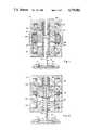
- FIGS. 1, 2 and 3show alternative single valve embodiments of the apparatus of this invention.
- FIG. 4shows a dual valve variation of the apparatus of this invention in which a single coil can actuate both valves at different current levels.
- FIG. 5is a section view along lines 5--5 in FIG. 4.
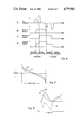
- FIGS. 6A-6Dshow timing diagrams of various parameters illustrating the operation of the apparatus of FIGS. 4-5.
- FIG. 7is a diagram of force vs. position for the springs and magnetic circuits of the embodiments of FIGS. 1-5 showing the bistable nature of the apparatus.
- FIG. 8is a timing diagram of various electrical parameters illustrating the use, in one of the embodiments of FIGS. 1-5, of the non-activated coil as a valve motion sensing feedback signal generating element.
- a valve closing member 10has a valve head 11 which, in a closed position, seats against and thereby closes an engine intake or exhaust port with a valve seat 12.
- Valve member 10has a stem 13 including, at a point spaced from head 11, an annular plunger 15 made of magnetic material and attached to stem 13 by a circular plate 16.
- the word "annular”, as used in this specification and the following claims,is not to be restricted to a circular shape. Rectangular and other shapes may be used. Another non-circular example is shown in the embodiment of FIGS. 4, 5, to be described at a later point in this specification.
- Plunger 15, magnetic frame members 17, 18 and permanent magnet 20together comprise a magnetic circuit having an annular radial air gap between the radially inner pole S of permanent magnet 20 and the radially outer surface 21 of plunger 15 which does not vary significantly with axial plunger movement.
- a variation of this structure not shown in the Figures but within the scope of the claimswould include a thin annular sleeve of a magnetic material such as soft steel on the inner annular surface of magnet 20 adjacent plunger 15. The purpose of the sleeve would be to better distribute the flux of magnet 20, prevent local demagnetization of the magnet, protect the magnet from chipping or other physical damage and generally facilitate assembly of the unit.
- plunger 15is preferably made with a plurality of axial slots extending radially inward from the outer circumference through a substantial portion of the annular thickness thereof to reduce eddy current losses.
- the use of twenty four evenly spaced slotshas produced energy savings of as much as 39 percent.
- the slotsshould be made as thin as possible to be practical.
- EDMElectric Discharge Machining
- the magnetic circuitfurther has an axial air gap between a first pole 22 formed by upper magnetic frame member 17 and the upper axial surface 23 and between a second pole 25 formed by lower magnetic frame member 18 and the lower axial surface 26.
- This compound magnetic circuitvaries with plunger 15, and therefore valve member 10, position to produce the magnetic force curve 27 of FIG. 7.
- An upper spring 28is compressed between upper magnetic frame member 17 and plate 16 of valve member 10.
- a lower spring 30is compressed between lower magnetic frame member 18 and plate 16.
- Springs 28 and 30are preferably coil springs; although other types may be used. They combine to produce a spring force on valve member 10 as shown by curve 31 of FIG. 7, a force always tending to return valve member 10 toward a neutral position between the open and closed positions thereof. The combined forces oppose each other and cancel to form two stable positions for valve member 10: one in the closed position shown in FIG. 1, with plunger 15 adjacent pole 22 of magnetic frame member 17; the other in the open position, with plunger 15 adjacent pole 25 of lower magnetic frame member 18. There is a potential third stable position in the neutral position midway between the others. However, in normal operation, as will be seen, this position is never a final resting place for the apparatus, which may be considered a bistable device.
- An upper coil 32is wound around pole 22 of upper magnetic frame member 17; and a lower coil 33 is wound around pole 25 of lower magnetic frame member 18.
- Each of coils 32 and 33is effective, when provided with a predetermined current pulse, to cancel the magnetic force of the adjacent pole, whereby the associated spring 28 or 30 imparts a rapid acceleration of valve member 10 out of its position adjacent the pole.
- the inertia of valve member 10carries it well past the neutral position midway between the poles, a position it passes with maximum velocity. Although, on the other side of the neutral position, valve member 10 loses kinetic energy as it compresses the other of springs 28 and 30, it coasts sufficiently close to the opposite pole to be attracted thereto. It thus becomes latched in the opposite position until the opposite coil is activated to return valve member 10 in like manner to its original position.
- the springdelivers high initial acceleration to produce high kinetic energy in valve member 10 and thus quick movement thereof, the kinetic energy is converted back to potential energy by the other spring, which tends to brake valve member 10 before it seats in the opposite position.
- no currentis required to maintain valve member 10 in either latched position, so that overall energy consumption of the apparatus is low.
- the initial spring loading of the apparatuscan be set in manufacturing with valve member 10 in one of the latched positions with no additional provision to periodically re-load the apparatus.
- FIG. 2A variation of the apparatus of FIG. 1 is shown in FIG. 2. Members which are essentially unchanged are given similar primed reference numerals.
- the permanent magnet 35is an annular magnet mounted on valve stem 13', which takes the place of both plunger 15 and plate 16 of FIG. 1.
- An annular magnetic flux member 36is placed between magnetic frame members 17 and 18 in place of permanent magnet 20 of FIG. 1 to complete the magnetic flux circuit.
- the operation of the apparatus of FIG. 2is identical with that of FIG. 1, already described.
- FIG. 3Another variation of the apparatus of FIG. 1 is shown in FIG. 3.
- essentially similar elementsare shown with double primed reference numerals.
- a pair of annular permanent magnets 37, 38is provided, one magnet for each of magnetic frame members 17" and 18", which members are axially separated from each other.
- Plate 16"is provided on valve stem 13" as in the embodiment of FIG. 1; but it extends radially across the full radial extent of members 17 and 18 with no annular plunger attached.
- the operation of the apparatus of FIG. 3is similar to that of FIGS.
- FIG. 3A variation of the embodiment of FIG. 3 is not separately shown, since it differs only in the replacement of permanent magnet 38 with a member of soft magnetic but not permanently magnetized material. Magnet 37 would still accomplish latching in the valve closed position and retain the valve closed after elctric power is shut off. Since the type of valves involved are closed most of the time, most of the valves in an engine would be in the permanent magnet latched closed state at any given time. There would be an increased energy requirement for retention of the valves in the open position; but the overall solenoid cost would be lower.
- FIGS. 4 and 5is a dual valve embodiment of the invention, where the dual valves are both of the same type (i.e., intake or exhaust) but one is designed to open before the other.
- An upper magnetic frame member 50defines a central pole 51 and outer annular pole 52.
- a lower magnetic frame member 53defines a central pole 55 and an outer annular pole 56.
- Members 50 and 53are joined together at their periphery and enclose an annular permanent magnet 57 positioned similarly to magnet 20 of FIG. 1.
- a pair of valves 58 and 58', which close against valve seats 70 and 70', respectively,have mounted thereon plates 60 and 60' and annular plungers 61 and 61', similarly to the arrangement of FIG. 1.
- a single upper coil 62surrounds poles 51 and 52 of upper magnetic frame member 50; a single lower coil 63 surrounds poles 55 and 56 of magnetic frame member 53.
- Springs 65 and 66urge valve 58 to a neutral position; while springs 65' and 66' urge valve 58' to a neutral position.
- each of valves 58 and 58'are bistable with a force characteristic as shown in curves 27 and 31 of FIG. 7; and the apparatus operates generally as does that of FIG. 1.
- the springs, magnetic circuits and coils of the apparatusare designed to cause one of valves 58 and 58' to be released from one of its latched positions at a lower current level than the other is released from its similar latched position.
- the spring constants of springs 65 and 66, on one hand, and springs 65' and 66', on the other hand,may be different or the magnetic circuits for the two valves 58 and 58' may be different.
- a current through coil 62for example, equal to the lower current should be sufficient to open valve 58, with a greater current through the same coil at a later time being effective to additionally open valve 58'.
- FIG. 6Ashows the coil current pulsed to a first maximum value to cause one of the valves to open, as shown in FIG. 6B. This is followed by a pulse to a larger maximum value which is sufficient to open the other valve as shown in FIG. 6C.
- the closing pulses and their resultsare shown in the same Figures.
- the apparatusmay be desirable, as part of the valve control for the apparatus of this invention, to provide a feedback signal indicating valve response to the activating currents of the coils. Since the apparatus has two coils--one to initiate valve opening and one to initiate valve closing--and only one is used at a time, the other coil is free to be used as a sensing coil. It is located in a position where it will change its inductance with motion of the valve apparatus and therefore will be effective to provide such feedback.
- FIG. 8shows valve motion in curve 67, activating current in the activating coil in curve 68 and generated EMF in the sensing coil in curve 80 for a case in which the valve rebounds from the desired position back toward the original position instead of latching in the desired position.
- the zero levels of curves 68 and 80are seen in the extreme left and right of curve 68.
- the sign of the EMFchanges on the rebound and thus is an indication thereof.
- the EMF just prior to reboundwas quite high (in the negative direction), which would provide an indication that rebound was about to occur.
- the controlcould be designed to respond to such a signal by applying a braking force by temporarily and partially cancelling the attractive magnetic force of the destination pole or by some other means, in order that rebound is prevented.
Landscapes
- Physics & Mathematics (AREA)
- Electromagnetism (AREA)
- Engineering & Computer Science (AREA)
- Power Engineering (AREA)
- Mechanical Engineering (AREA)
- General Engineering & Computer Science (AREA)
- Magnetically Actuated Valves (AREA)
Abstract
Description
This invention relates to bistable electromechanical actuators such as those which may be used with intake and exhaust valves for the combustion chambers of an internal combustion engine. Such valves are customarily mechanically activated by a camshaft; but several actuators using electromagnetic forces have been suggested in the prior art. The latter actuators, if practical, have potential for improving engine performance by providing control of intake and/or exhaust valve operation and thus making valve timing variable in engine operation; however, none suggested so far has been sufficiently practical to supplant the ordinary mechanical actuating schemes.
One type of electromagnetic valve actuating device which has been suggested is the solenoid. Conventional solenoids operate by electromagnetically generated attractive forces built by inducing a flux in a moving armature. The magnitude of these forces, however, decreases rapidly over the distance which the armature travels. In typical engine valve applications, this is equal to the valve lift of typically 10 mm, a comparatively large distance. One proposed solution is the helenoid actuator suggested by A. H. Seilly in the SAE Paper No. 790119 entitled "Helenoid Actuators--A New Concept in Extremely Fast Acting Solenoids", published in 1979. In a helenoid actuator, a plunger is moved over a smaller gap with the displacement being amplified by a lever. The lever, however, adds mass to the system; and a large amount of energy is required to move the valve.
A magnet in the armature can help generate strong repulsion forces at the beginning of the armature motion, as shown in the U.S. Pat. Nos. to Kramer 3,202,886, issued Aug. 24, 1965, Stanwell 3,504,315, issued Mar. 31, 1970 and Patel 4,533,890, issued Aug. 6, 1985. However, the solenoid current level of these schemes is high, since it must generate sufficient force to overcome the magnetic attraction as well as to provide the kinetic energy of valve motion. In addition, due to the high seating velocity, braking means may be required for the valve.
Oscillating systems of the spring-mass type, for example, can store amounts of energy significantly larger than the small amount of energy required to overcome friction and spring losses. Solenoids can be used to latch such a system at either end of its stroke. In addition, magnetic forces from the solenoid can compensate for the losses of the system. Such a system is shown in the U.S. Pat. No. 4,455,543 to Pischinger et al, issued June 19, 1984. However, in the system of that patent, electrical energy is continuously consumed while the valve is latched in either of the open and closed positions. In addition, upon system initiation, provision must be made to preload the system by moving the valve against the springs to the open or closed position from a middle position to which it returns when neither solenoid is actuated. A third coil is proposed; and this adds to the complexity of the device. An alternative initialization method not requiring the third coil is proposed in the U.S. Pat. No. 4,614,170 to Pischinger et al. However, this method requires complex control routines and delays start up. In addition, since the valves are open in an intermediate position when the engine is off, Pishinger et al add an auxiliary valve (30 in FIG. 5), which further increases cost and complexity.
The apparatus of this invention retains the advantageous features of a solenoid latched spring-mass oscillating system but with reduced energy consumption and no need for preloading upon startup.
The appartus of the invention uses permanent magnets to latch the valve closing member into at least the closed position and, in some embodiments, the open position, against the force of compressed springs. Recently developed powerful permanent magnetic materials enable such magnets to be small and light. A coil associated with each position, when activated with a current, cancels the magnetic field of the permanent magnet pole holding the valve closing member and allows the compressed spring to move the member quickly through a central neutral position toward the other position, whereupon it is attracted by the other magnetic pole to compress the other spring and latch into the other position.
Variations on the basic invention include different structures for single valves, the inclusion of two valves within a single pair of coils with different opening current levels so that a first current level within the appropriate coil releases the first valve with a higher current required to release the second valve. In addition, since there is a coil for each of the closed and open positions, one coil may be used as a valve movement sensing element while the other is being activated so as to provide valve movement confirming feedback to a control system utilizing the apparatus. Further details and advantages of the invention will be apparent from the accompanying drawings and following description of a preferred embodiment.
FIGS. 1, 2 and 3 show alternative single valve embodiments of the apparatus of this invention.
FIG. 4 shows a dual valve variation of the apparatus of this invention in which a single coil can actuate both valves at different current levels.
FIG. 5 is a section view alonglines 5--5 in FIG. 4.
FIGS. 6A-6D show timing diagrams of various parameters illustrating the operation of the apparatus of FIGS. 4-5.
FIG. 7 is a diagram of force vs. position for the springs and magnetic circuits of the embodiments of FIGS. 1-5 showing the bistable nature of the apparatus.
FIG. 8 is a timing diagram of various electrical parameters illustrating the use, in one of the embodiments of FIGS. 1-5, of the non-activated coil as a valve motion sensing feedback signal generating element.
Referring to FIG. 1, avalve closing member 10 has avalve head 11 which, in a closed position, seats against and thereby closes an engine intake or exhaust port with avalve seat 12. Valvemember 10 has astem 13 including, at a point spaced fromhead 11, anannular plunger 15 made of magnetic material and attached tostem 13 by acircular plate 16. Upper and lowermagnetic frame members permanent magnet 20 having radially inner and outer poles. The word "annular", as used in this specification and the following claims, is not to be restricted to a circular shape. Rectangular and other shapes may be used. Another non-circular example is shown in the embodiment of FIGS. 4, 5, to be described at a later point in this specification.Plunger 15,magnetic frame members permanent magnet 20 together comprise a magnetic circuit having an annular radial air gap between the radially inner pole S ofpermanent magnet 20 and the radiallyouter surface 21 ofplunger 15 which does not vary significantly with axial plunger movement. A variation of this structure not shown in the Figures but within the scope of the claims would include a thin annular sleeve of a magnetic material such as soft steel on the inner annular surface ofmagnet 20adjacent plunger 15. The purpose of the sleeve would be to better distribute the flux ofmagnet 20, prevent local demagnetization of the magnet, protect the magnet from chipping or other physical damage and generally facilitate assembly of the unit.
Although it does not show in FIG. 1,plunger 15 is preferably made with a plurality of axial slots extending radially inward from the outer circumference through a substantial portion of the annular thickness thereof to reduce eddy current losses. For example, the use of twenty four evenly spaced slots has produced energy savings of as much as 39 percent. The slots should be made as thin as possible to be practical. The use of an Electric Discharge Machining (EDM) technique has produced slots as narrow as 0.004 inches, which removes a negligible amount of material fromplunger 15.
The magnetic circuit further has an axial air gap between afirst pole 22 formed by uppermagnetic frame member 17 and the upperaxial surface 23 and between asecond pole 25 formed by lowermagnetic frame member 18 and the loweraxial surface 26. This compound magnetic circuit varies withplunger 15, and thereforevalve member 10, position to produce themagnetic force curve 27 of FIG. 7.
Anupper spring 28 is compressed between uppermagnetic frame member 17 andplate 16 ofvalve member 10. Alower spring 30 is compressed between lowermagnetic frame member 18 andplate 16.Springs valve member 10 as shown bycurve 31 of FIG. 7, a force always tending to returnvalve member 10 toward a neutral position between the open and closed positions thereof. The combined forces oppose each other and cancel to form two stable positions for valve member 10: one in the closed position shown in FIG. 1, withplunger 15adjacent pole 22 ofmagnetic frame member 17; the other in the open position, withplunger 15adjacent pole 25 of lowermagnetic frame member 18. There is a potential third stable position in the neutral position midway between the others. However, in normal operation, as will be seen, this position is never a final resting place for the apparatus, which may be considered a bistable device.
Anupper coil 32 is wound aroundpole 22 of uppermagnetic frame member 17; and alower coil 33 is wound aroundpole 25 of lowermagnetic frame member 18. Each ofcoils spring valve member 10 out of its position adjacent the pole. The inertia ofvalve member 10 carries it well past the neutral position midway between the poles, a position it passes with maximum velocity. Although, on the other side of the neutral position,valve member 10 loses kinetic energy as it compresses the other ofsprings valve member 10 in like manner to its original position.
Several advantages of the operation of this apparatus should be noted. First, although the spring delivers high initial acceleration to produce high kinetic energy invalve member 10 and thus quick movement thereof, the kinetic energy is converted back to potential energy by the other spring, which tends to brakevalve member 10 before it seats in the opposite position. Secondly, no current is required to maintainvalve member 10 in either latched position, so that overall energy consumption of the apparatus is low. Thirdly, the initial spring loading of the apparatus can be set in manufacturing withvalve member 10 in one of the latched positions with no additional provision to periodically re-load the apparatus.
A variation of the apparatus of FIG. 1 is shown in FIG. 2. Members which are essentially unchanged are given similar primed reference numerals. In this embodiment, thepermanent magnet 35 is an annular magnet mounted on valve stem 13', which takes the place of bothplunger 15 andplate 16 of FIG. 1. An annularmagnetic flux member 36 is placed betweenmagnetic frame members permanent magnet 20 of FIG. 1 to complete the magnetic flux circuit. The operation of the apparatus of FIG. 2 is identical with that of FIG. 1, already described.
Another variation of the apparatus of FIG. 1 is shown in FIG. 3. In this embodiment, essentially similar elements are shown with double primed reference numerals. A pair of annularpermanent magnets magnetic frame members 17" and 18", which members are axially separated from each other.Plate 16" is provided onvalve stem 13" as in the embodiment of FIG. 1; but it extends radially across the full radial extent ofmembers plate 16" completing the magnetic circuit between innerannular pole 22" and an outerannular pole 40 ofmagnetic frame member 17 at the upper limit of its travel and a magnetic circuit between innerannular pole 25" and an outerannular pole 41 ofmagnetic frame member 18 at the lower limit of its travel, which limits correspond to the closed and open positions, respectively.
A variation of the embodiment of FIG. 3 is not separately shown, since it differs only in the replacement ofpermanent magnet 38 with a member of soft magnetic but not permanently magnetized material.Magnet 37 would still accomplish latching in the valve closed position and retain the valve closed after elctric power is shut off. Since the type of valves involved are closed most of the time, most of the valves in an engine would be in the permanent magnet latched closed state at any given time. There would be an increased energy requirement for retention of the valves in the open position; but the overall solenoid cost would be lower.
The apparatus of FIGS. 4 and 5 is a dual valve embodiment of the invention, where the dual valves are both of the same type (i.e., intake or exhaust) but one is designed to open before the other. An uppermagnetic frame member 50 defines acentral pole 51 and outerannular pole 52. Similarly a lowermagnetic frame member 53 defines acentral pole 55 and an outerannular pole 56.Members permanent magnet 57 positioned similarly tomagnet 20 of FIG. 1. A pair ofvalves 58 and 58', which close againstvalve seats 70 and 70', respectively, have mounted thereonplates 60 and 60' andannular plungers 61 and 61', similarly to the arrangement of FIG. 1. A singleupper coil 62 surroundspoles magnetic frame member 50; a singlelower coil 63 surroundspoles magnetic frame member 53.Springs valve 58 to a neutral position; while springs 65' and 66' urge valve 58' to a neutral position. However, each ofvalves 58 and 58' are bistable with a force characteristic as shown incurves
However, not easily shown in FIGS. 4 and 5 is the fact that the springs, magnetic circuits and coils of the apparatus are designed to cause one ofvalves 58 and 58' to be released from one of its latched positions at a lower current level than the other is released from its similar latched position. To this end, the spring constants ofsprings valves 58 and 58' may be different. Thus, a current throughcoil 62, for example, equal to the lower current should be sufficient to openvalve 58, with a greater current through the same coil at a later time being effective to additionally open valve 58'. The operation is shown in the curves of FIGS. 6A-6D for opening and closing of the valves. FIG. 6A shows the coil current pulsed to a first maximum value to cause one of the valves to open, as shown in FIG. 6B. This is followed by a pulse to a larger maximum value which is sufficient to open the other valve as shown in FIG. 6C. The closing pulses and their results are shown in the same Figures. The overall charge intake total, assuming the valves are combustion chamber intake valves, is shown in FIG. 6D. Thus, a more complex valve opening profile is possible with control of valve and profile timing in a dual valve apparatus which is significantly more compact than dual solenoids.
It may be desirable, as part of the valve control for the apparatus of this invention, to provide a feedback signal indicating valve response to the activating currents of the coils. Since the apparatus has two coils--one to initiate valve opening and one to initiate valve closing--and only one is used at a time, the other coil is free to be used as a sensing coil. It is located in a position where it will change its inductance with motion of the valve apparatus and therefore will be effective to provide such feedback.
FIG. 8 shows valve motion incurve 67, activating current in the activating coil incurve 68 and generated EMF in the sensing coil incurve 80 for a case in which the valve rebounds from the desired position back toward the original position instead of latching in the desired position. The zero levels ofcurves curve 68. It should be noted that the sign of the EMF changes on the rebound and thus is an indication thereof. It should also be noted that the EMF just prior to rebound was quite high (in the negative direction), which would provide an indication that rebound was about to occur. The control could be designed to respond to such a signal by applying a braking force by temporarily and partially cancelling the attractive magnetic force of the destination pole or by some other means, in order that rebound is prevented.
Claims (4)
1. An electromechanical valve actuating device for an internal combustion engine, the valve comprising a valve closing member movable between a closed position against a valve seat and an open position away from the valve seat, the valve actuating device comprising, in combination:
spring means effective to bias the valve toward a neutral position between the closed and open positions;
permanent magnet means;
magnetic means including the permanent magnet means establishing a pair of magnetic flux circuits with magnetic pole pieces, at least a portion of the magnetic means being fixed to the valve for movement therewith so as to approach one of the pole pieces in the closed position of the valve and the other of the pole pieces in the open position of the valve, each of the magnetic flux circuit including an air gap between the portion of the magnetic means and the respective pole piece which decreases as the portion of the magnetic means approaches the respective pole piece and is significantly greater in the neutral position so as to create a magnetic attraction between the portion of the magnetic means and the respective pole piece which increases as the former approaches the latter and is sufficient, with the valve closing member in either of its closed or open positions to retain the valve in that position against the force of the spring; and
a pair of coils associated with the magnetic means, one for each of the closed and open positions of the valve, each of the coils positioned and wound so as to be effective when activated with an electric current therethrough to cancel the flux from the associated permanent magnet and thus the magnetic attraction between the corresponding pole piece and the portion of the magnetic means fixed to the valve, whereby the spring means is effective to move the valve closing member away from the corresponding pole piece and through the neutral position toward the other pole piece, whereby the valve closing member is attracted and retained in the other of the closed and open positions.
2. The electromechanical valve actuating device of claim 1 which includes first and second valve closing members independently movable between closed positions against first and second valve seats, respectively and open positions away from the first and second valve seats, the magnetic means being effective to establish a magnetic flux circuit with opposed magnetic pole pieces for each valve closing member, the spring means being effective to bias each valve closing member toward a neutral position between the closed and open positions, each of the pair of coils being associated with both the first and second magnetic means, and the magnetic means, spring means and coils together establishing a difference between the first and second valve closing members in the current level in the coils required to release the valve closing member from one of the open and closed positions, whereby a first current level in one of the coils is sufficient to release one of the first and second valve closing members from one of the open and closed positions and a second, higher current level is required to release the other of the first and second valve closing member from the same position.
3. The electromechanical valve actuating device of claim 1 further comprising means associated with one of the coils to detect, by means of fluctuations in an electrical parameter of the one of the coils, movement of the valve closing member due to activation of the other of the coils.
4. An electromechanical valve actuating device for an internal combustion engine, the valve comprising a valve closing member movable between a closed position against a valve seat and an open position away from the valve seat, the valve actuating device comprising, in combination:
spring means effective to bias the valve toward a neutral position between the closed and open positions;
a permanent magnet;
magnetic means including at least a portion of the valve closing member projecting between the first and second coils, the magnetic means being effective to establish a magnetic flux circuit including the portion of the valve closing member, a pole piece, the permanent magnet and a first air gap between the pole piece and the portion of the valve closing member which decreases as the valve closing member approaches the closed position from the neutral position;
a coil adjacent the permanent magnet, the coil being positioned and wound so as to be effective when activated with an electric current therethrough to cancel the magnetic attraction between the first pole piece and the portion of the valve closing member, whereby the spring means is effective to move the valve closing member away from the closed position and through the neutral position toward the open position;
means for selectively retaining the valve closing member in the open position.
Priority Applications (3)
| Application Number | Priority Date | Filing Date | Title |
|---|---|---|---|
| US07/084,400US4779582A (en) | 1987-08-12 | 1987-08-12 | Bistable electromechanical valve actuator |
| GB08816557AGB2208041A (en) | 1987-08-12 | 1988-07-12 | Electromechanical valve actuating apparatus |
| US07/240,284US4829947A (en) | 1987-08-12 | 1988-09-06 | Variable lift operation of bistable electromechanical poppet valve actuator |
Applications Claiming Priority (1)
| Application Number | Priority Date | Filing Date | Title |
|---|---|---|---|
| US07/084,400US4779582A (en) | 1987-08-12 | 1987-08-12 | Bistable electromechanical valve actuator |
Related Child Applications (1)
| Application Number | Title | Priority Date | Filing Date |
|---|---|---|---|
| US07/240,284Continuation-In-PartUS4829947A (en) | 1987-08-12 | 1988-09-06 | Variable lift operation of bistable electromechanical poppet valve actuator |
Publications (1)
| Publication Number | Publication Date |
|---|---|
| US4779582Atrue US4779582A (en) | 1988-10-25 |
Family
ID=22184733
Family Applications (1)
| Application Number | Title | Priority Date | Filing Date |
|---|---|---|---|
| US07/084,400Expired - Fee RelatedUS4779582A (en) | 1987-08-12 | 1987-08-12 | Bistable electromechanical valve actuator |
Country Status (2)
| Country | Link |
|---|---|
| US (1) | US4779582A (en) |
| GB (1) | GB2208041A (en) |
Cited By (93)
| Publication number | Priority date | Publication date | Assignee | Title |
|---|---|---|---|---|
| US4831973A (en)* | 1988-02-08 | 1989-05-23 | Magnavox Government And Industrial Electronics Company | Repulsion actuated potential energy driven valve mechanism |
| US4883025A (en)* | 1988-02-08 | 1989-11-28 | Magnavox Government And Industrial Electronics Company | Potential-magnetic energy driven valve mechanism |
| US4938179A (en)* | 1988-12-28 | 1990-07-03 | Isuzu Motors Limited | Valve control system for internal combustion engine |
| EP0376715A3 (en)* | 1988-12-29 | 1990-08-08 | Isuzu Motors Limited | Electromagnetic-force valve-driving apparatus |
| EP0395450A1 (en)* | 1989-04-28 | 1990-10-31 | Isuzu Ceramics Research Institute Co., Ltd. | Intake/exhaust valve actuator |
| EP0405191A1 (en)* | 1989-06-27 | 1991-01-02 | FEV Motorentechnik GmbH & Co. KG | Electromagnetic positioning device |
| US4984541A (en)* | 1989-03-30 | 1991-01-15 | Isuzu Ceramics Research Institute Co., Ltd. | Valve stepping drive apparatus |
| US5074259A (en)* | 1990-05-09 | 1991-12-24 | Pavo Pusic | Electrically operated cylinder valve |
| US5080323A (en)* | 1988-08-09 | 1992-01-14 | Audi A.G. | Adjusting device for gas exchange valves |
| US5095856A (en)* | 1988-12-28 | 1992-03-17 | Isuzu Ceramics Research Institute Co., Ltd. | Electromagnetic valve actuating system |
| WO1991010242A3 (en)* | 1989-12-22 | 1992-06-25 | Square D Deutschland | Magnetic drive with permanent-magnet solenoid armature |
| EP0493633A1 (en)* | 1990-12-31 | 1992-07-08 | Isuzu Ceramics Research Institute Co., Ltd. | Electromagnetic valve control system |
| EP0493634A1 (en)* | 1989-12-12 | 1992-07-08 | Isuzu Ceramics Research Institute Co., Ltd. | Electromagnetic valve control system |
| US5216987A (en)* | 1992-06-01 | 1993-06-08 | Caterpillar Inc. | Method and apparatus for optimizing breathing utilizing unit valve actuation |
| US5300908A (en)* | 1990-10-10 | 1994-04-05 | Brady Usa, Inc. | High speed solenoid |
| WO1994027303A1 (en)* | 1993-05-19 | 1994-11-24 | Moving Magnet Technologies S.A. | Monophase, short travel, electromagnetic actuator having a good electric power/force ratio |
| DE19506566A1 (en)* | 1995-02-24 | 1996-08-29 | Bayerische Motoren Werke Ag | Electromagnetic piston valve actuation device for internal combustion engine |
| EP0799394A4 (en)* | 1994-04-28 | 1997-10-08 | ||
| EP0841473A1 (en)* | 1996-11-12 | 1998-05-13 | Ford Global Technologies, Inc. | Electromechanically actuated valve for an internal combustion engine |
| EP0870906A1 (en)* | 1997-04-08 | 1998-10-14 | Bayerische Motoren Werke Aktiengesellschaft, Patentabteilung AJ-3 | Electromagnetic actuator for the control of a gas exchange valve of an internal combustion engine |
| US5883557A (en)* | 1997-10-31 | 1999-03-16 | General Motors Corporation | Magnetically latching solenoid apparatus |
| US6039014A (en)* | 1998-06-01 | 2000-03-21 | Eaton Corporation | System and method for regenerative electromagnetic engine valve actuation |
| FR2791487A1 (en)* | 1999-03-26 | 2000-09-29 | Moving Magnet Tech | METHOD FOR DETERMINING THE POSITION OF A MOBILE MEMBER IN AT LEAST ONE MAIN GAP OF AN ELECTROMAGNETIC ACTUATOR |
| FR2792031A1 (en)* | 1999-04-09 | 2000-10-13 | Sagem | ELECTROMAGNETIC VALVE CONTROL DEVICE |
| US6164322A (en)* | 1999-01-15 | 2000-12-26 | Saturn Electronic & Engineering, Inc. | Pressure relief latching solenoid valve |
| US6170445B1 (en) | 1998-11-19 | 2001-01-09 | Toyota Jidosha Kabushiki Kaisha | Electromagnetic actuating system of internal combustion engine |
| DE19943620A1 (en)* | 1999-09-11 | 2001-03-15 | Bayerische Motoren Werke Ag | Device with an electromagnetic actuator for actuating a gas exchange valve of an internal combustion engine |
| US6216653B1 (en) | 1999-03-31 | 2001-04-17 | Unisia Jecs Corporation | Electromagnetic valve actuator for a valve of an engine |
| US6220210B1 (en)* | 1999-03-29 | 2001-04-24 | Honda Giken Kogyo Kabushiki Kaisha | Solenoid valve driving device |
| US6234122B1 (en)* | 1998-11-16 | 2001-05-22 | Daimlerchrysler Ag | Method for driving an electromagnetic actuator for operating a gas change valve |
| EP0982521A3 (en)* | 1998-08-21 | 2001-08-08 | Bayerische Motoren Werke Aktiengesellschaft | Electromagnetic actuator for actuating a valve with a frame shaped housing, in particular for an internal combustion engine |
| DE10008991A1 (en)* | 2000-02-25 | 2001-08-30 | Bayerische Motoren Werke Ag | Gas exchange valve regulation with electromagnetic actuator for IC engines has armature separating gas springs and defining damper chamber in holding position on magnet |
| DE10008975A1 (en)* | 2000-02-25 | 2001-08-30 | Bayerische Motoren Werke Ag | Electromagnetic actuator for gas replacement valve for internal combustion engine has device for applying increased acceleration force on armature when in holding position |
| US6334413B1 (en) | 1998-12-07 | 2002-01-01 | Toyota Jidosha Kabushiki Kaisha | Electromagnetic actuating system |
| US6575126B2 (en)* | 1994-04-05 | 2003-06-10 | Sturman Industries, Inc. | Solenoid actuated engine valve for an internal combustion engine |
| US6763789B1 (en) | 2003-04-01 | 2004-07-20 | Ford Global Technologies, Llc | Electromagnetic actuator with permanent magnet |
| US6791442B1 (en) | 2003-11-21 | 2004-09-14 | Trombetta, Llc | Magnetic latching solenoid |
| US20040206922A1 (en)* | 2003-02-26 | 2004-10-21 | Du Plessis Andries J. | Position control actuator system |
| US20040239460A1 (en)* | 1999-12-06 | 2004-12-02 | Franz Kocijan | Switchable magnetic device |
| US20050076866A1 (en)* | 2003-10-14 | 2005-04-14 | Hopper Mark L. | Electromechanical valve actuator |
| US20050194184A1 (en)* | 2004-03-04 | 2005-09-08 | Gleitman Daniel D. | Multiple distributed pressure measurements |
| US20050205059A1 (en)* | 2004-03-19 | 2005-09-22 | Lewis Donald J | Engine breathing in an engine with mechanical and electromechanical valves |
| US20050211199A1 (en)* | 2004-03-25 | 2005-09-29 | Feng Liang | Permanent magnet electromagnetic actuator for an electronic valve actuation system of an engine |
| US20050211200A1 (en)* | 2004-03-25 | 2005-09-29 | Feng Liang | Enhanced permanent magnet electromagnetic actuator for an electronic valve actuation system of an engine |
| US20060071748A1 (en)* | 2004-10-06 | 2006-04-06 | Victor Nelson | Latching linear solenoid |
| US7066121B2 (en) | 2004-03-19 | 2006-06-27 | Ford Global Technologies, Llc | Cylinder and valve mode control for an engine with valves that may be deactivated |
| US20060138373A1 (en)* | 2004-12-23 | 2006-06-29 | Luk Lamellen Und Kupplungsbau Beteiligungs Kg | Solenoid valve device |
| US20060208842A1 (en)* | 2002-12-02 | 2006-09-21 | Valeo Systemes De Controle Moteur | Mobile member speed sensor |
| US20060231783A1 (en)* | 2003-05-26 | 2006-10-19 | Continental Teves Ag & Co. Ohg | Valve drive for a gas exchange valve |
| EP1698817A3 (en)* | 2005-03-05 | 2007-05-30 | Arichell Technologies, Inc. | Electromagnetic apparatus and method for controlling fluid flow |
| US20070245982A1 (en)* | 2006-04-20 | 2007-10-25 | Sturman Digital Systems, Llc | Low emission high performance engines, multiple cylinder engines and operating methods |
| US20080238594A1 (en)* | 2005-09-09 | 2008-10-02 | Jinping Liu | Low-Power Numerically Controlled Contactor and Control System Made of the Contactors |
| US20080264393A1 (en)* | 2007-04-30 | 2008-10-30 | Sturman Digital Systems, Llc | Methods of Operating Low Emission High Performance Compression Ignition Engines |
| US20090058579A1 (en)* | 2006-04-13 | 2009-03-05 | Hubert Greif | Magnet assembly for a magnet valve |
| CN100476164C (en)* | 2004-06-21 | 2009-04-08 | 福特环球技术公司 | An Improved Permanent Magnet Electromagnetic Actuator Used in Engine Electronic Valve Actuation System |
| WO2009056221A1 (en)* | 2007-11-02 | 2009-05-07 | Daimler Ag | Valve operating mechanism |
| WO2009062155A1 (en) | 2007-11-08 | 2009-05-14 | Engineering Matters, Inc. | Flexible electromagnetic valve actuator modeling and performance |
| US20090121558A1 (en)* | 2007-11-08 | 2009-05-14 | Engineering Matters, Inc. | Flexible Electromagnetic Valve Actuator Modeling and Performance |
| US20090183699A1 (en)* | 2008-01-18 | 2009-07-23 | Sturman Digital Systems, Llc | Compression Ignition Engines and Methods |
| US20090236931A1 (en)* | 2008-03-19 | 2009-09-24 | Olympus Corporation | Shape memory alloy actuator |
| WO2010015328A1 (en)* | 2008-08-05 | 2010-02-11 | Daimler Ag | Valve drive device |
| WO2010063394A1 (en)* | 2008-12-03 | 2010-06-10 | Eto Magnetic Gmbh | Electromagnetic actuator device |
| WO2011058344A1 (en) | 2009-11-10 | 2011-05-19 | Sentec Ltd | Solenoid actuator |
| US7954472B1 (en) | 2007-10-24 | 2011-06-07 | Sturman Digital Systems, Llc | High performance, low emission engines, multiple cylinder engines and operating methods |
| US20110240892A1 (en)* | 2009-02-27 | 2011-10-06 | Schaeffler Technologies Gmbh & Co. Kg | Electromagnetic actuating device |
| US20130222083A1 (en)* | 2010-11-03 | 2013-08-29 | Jiangsu Modern Capacitor Co., Ltd. | Soft-collision electromagnetic driving mechanism |
| US8596230B2 (en) | 2009-10-12 | 2013-12-03 | Sturman Digital Systems, Llc | Hydraulic internal combustion engines |
| US20130333909A1 (en)* | 2012-06-15 | 2013-12-19 | Hilti Aktiengesellschaft | Machine tool |
| CN103608617A (en)* | 2011-06-14 | 2014-02-26 | 森泰克有限公司 | Solenoid actuator |
| US20140062628A1 (en)* | 2012-08-28 | 2014-03-06 | Eto Magnetic Gmbh | Electromagnetic actuator device |
| US8887690B1 (en) | 2010-07-12 | 2014-11-18 | Sturman Digital Systems, Llc | Ammonia fueled mobile and stationary systems and methods |
| US20150162155A1 (en)* | 2013-12-11 | 2015-06-11 | Dayco Ip Holdings, Llc | Magnetically actuated shut-off valve |
| US20150260135A1 (en)* | 2014-03-14 | 2015-09-17 | Continental Automotive Gmbh | Fuel injector |
| WO2015140585A1 (en)* | 2014-03-19 | 2015-09-24 | Sümegi István Andor | Bistable electromechanical magnetic locking device |
| US9206738B2 (en) | 2011-06-20 | 2015-12-08 | Sturman Digital Systems, Llc | Free piston engines with single hydraulic piston actuator and methods |
| US20160125991A1 (en)* | 2014-10-31 | 2016-05-05 | Husco Automotive Holding Llc | Methods and Systems For Push Pin Actuator |
| US9368266B2 (en) | 2014-07-18 | 2016-06-14 | Trumpet Holdings, Inc. | Electric solenoid structure having elastomeric biasing member |
| US9435460B2 (en) | 2000-02-29 | 2016-09-06 | Sloan Value Company | Electromagnetic apparatus and method for controlling fluid flow |
| US20160293310A1 (en)* | 2013-05-29 | 2016-10-06 | Active Signal Technologies, Inc. | Electromagnetic opposing field actuators |
| US9464569B2 (en) | 2011-07-29 | 2016-10-11 | Sturman Digital Systems, Llc | Digital hydraulic opposed free piston engines and methods |
| US9478339B2 (en) | 2015-01-27 | 2016-10-25 | American Axle & Manufacturing, Inc. | Magnetically latching two position actuator and a clutched device having a magnetically latching two position actuator |
| US9574677B2 (en) | 2013-05-31 | 2017-02-21 | Dayco Ip Holdings, Llc | Solenoid-powered gate valve |
| US9599246B2 (en) | 2015-08-05 | 2017-03-21 | Dayco Ip Holdings, Llc | Magnetically actuated shut-off valve |
| WO2017068285A1 (en) | 2015-10-20 | 2017-04-27 | Moving Magnet Technologies | Linear actuator with improved magnetic stability and stripping force |
| DE102016203602A1 (en)* | 2016-03-04 | 2017-09-07 | Zf Friedrichshafen Ag | Electromagnetic actuator and valve |
| US9841110B2 (en) | 2013-08-30 | 2017-12-12 | Dayco Ip Holdings, Llc | Sprung gate valves movable by a solenoid actuator |
| US9845899B2 (en) | 2013-05-31 | 2017-12-19 | Dayco Ip Holdings, Llc | Sprung gate valves movable by an actuator |
| WO2018149694A1 (en)* | 2017-02-15 | 2018-08-23 | Kolektor Group D.O.O. | Electromagnetic linear actuator |
| US10221867B2 (en) | 2013-12-10 | 2019-03-05 | Dayco Ip Holdings, Llc | Flow control for aspirators producing vacuum using the venturi effect |
| DE102017125786A1 (en)* | 2017-11-06 | 2019-05-09 | Schaeffler Technologies AG & Co. KG | Bistable linear magnet |
| WO2020173996A1 (en)* | 2019-02-26 | 2020-09-03 | Eto Magnetic Gmbh | Actuator device and method for operating an actuator device |
| US20230069994A1 (en)* | 2020-01-29 | 2023-03-09 | Purpose Co., Ltd. | Proportional solenoid valve control method, proportional solenoid valve system, proportional solenoid valve control device, valve opening degree control program, proportional solenoid valve, heat source device, heat source device control method, heat source device control program, recording medium, control device, and hot water supply device |
| US20250224045A1 (en)* | 2024-01-09 | 2025-07-10 | The Boeing Company | Propellant Valve |
Families Citing this family (8)
| Publication number | Priority date | Publication date | Assignee | Title |
|---|---|---|---|---|
| DE4215145A1 (en)* | 1992-05-08 | 1993-11-11 | Rexroth Mannesmann Gmbh | Linear control motor esp. as part of control or regulating valve - has control coils adjacent permanent magnets inside tubular housing with movable armature |
| GB2271668A (en)* | 1992-05-29 | 1994-04-20 | Westinghouse Electric Corp | Bistable magnetic actuator |
| GB2319296A (en)* | 1996-11-13 | 1998-05-20 | Bernard Owen | I.c. engine with valves actuated electrically, eg electromagnetically |
| DE29907923U1 (en)* | 1999-05-04 | 1999-08-12 | Sheng Chih Sheng | Magnetic device with exchangeable magnetic circuit and with both fastening points |
| DE10038575B4 (en)* | 2000-08-03 | 2010-09-09 | Hörmansdörfer, Gerd | Electromagnetic actuator |
| DE10133380A1 (en)* | 2001-07-10 | 2003-01-23 | Bayerische Motoren Werke Ag | Method for detecting and controlling position of moveable object, especially internal combustion (IC) engine valve, requires control device for controlling valve on basis of detected flux density |
| GB0705487D0 (en)* | 2007-03-22 | 2007-05-02 | Bifold Fluidpower Ltd | A latching solenoid |
| DE102012018566A1 (en)* | 2012-09-20 | 2014-03-20 | Festo Ag & Co. Kg | Valve device for use as e.g. proportional valve, has valve housing provided with permanent magnet arrangement, and multiple flux conductive pieces arranged on axis of electrical operable coil arrangement |
Citations (9)
| Publication number | Priority date | Publication date | Assignee | Title |
|---|---|---|---|---|
| US1471861A (en)* | 1921-09-07 | 1923-10-23 | Perrault Oscar Louis | Valve-actuating mechanism for internal-combustion engines |
| US3202886A (en)* | 1962-01-11 | 1965-08-24 | Bulova Watch Co Inc | Bistable solenoid |
| US3504315A (en)* | 1967-12-05 | 1970-03-31 | Plessey Co Ltd | Electrical solenoid devices |
| US3853102A (en)* | 1973-05-31 | 1974-12-10 | L Harvill | Magnetic valve train for combustion engines |
| US3882833A (en)* | 1972-07-12 | 1975-05-13 | British Leyland Austin Morris | Internal combustion engines |
| US4383234A (en)* | 1981-10-14 | 1983-05-10 | The Singer Company | Magnetic latch valve |
| US4455543A (en)* | 1980-06-27 | 1984-06-19 | Franz Pischinger | Electromagnetically operating actuator |
| US4533890A (en)* | 1984-12-24 | 1985-08-06 | General Motors Corporation | Permanent magnet bistable solenoid actuator |
| US4614170A (en)* | 1983-03-01 | 1986-09-30 | Fev Forschungsgessellschaft Fur Energietechnik Und Verbrennungsmotoren Mbh | Method of starting a valve regulating apparatus for displacement-type machines |
- 1987
- 1987-08-12USUS07/084,400patent/US4779582A/ennot_activeExpired - Fee Related
- 1988
- 1988-07-12GBGB08816557Apatent/GB2208041A/ennot_activeWithdrawn
Patent Citations (9)
| Publication number | Priority date | Publication date | Assignee | Title |
|---|---|---|---|---|
| US1471861A (en)* | 1921-09-07 | 1923-10-23 | Perrault Oscar Louis | Valve-actuating mechanism for internal-combustion engines |
| US3202886A (en)* | 1962-01-11 | 1965-08-24 | Bulova Watch Co Inc | Bistable solenoid |
| US3504315A (en)* | 1967-12-05 | 1970-03-31 | Plessey Co Ltd | Electrical solenoid devices |
| US3882833A (en)* | 1972-07-12 | 1975-05-13 | British Leyland Austin Morris | Internal combustion engines |
| US3853102A (en)* | 1973-05-31 | 1974-12-10 | L Harvill | Magnetic valve train for combustion engines |
| US4455543A (en)* | 1980-06-27 | 1984-06-19 | Franz Pischinger | Electromagnetically operating actuator |
| US4383234A (en)* | 1981-10-14 | 1983-05-10 | The Singer Company | Magnetic latch valve |
| US4614170A (en)* | 1983-03-01 | 1986-09-30 | Fev Forschungsgessellschaft Fur Energietechnik Und Verbrennungsmotoren Mbh | Method of starting a valve regulating apparatus for displacement-type machines |
| US4533890A (en)* | 1984-12-24 | 1985-08-06 | General Motors Corporation | Permanent magnet bistable solenoid actuator |
Non-Patent Citations (2)
| Title |
|---|
| SAE Paper No. 790119 Entitled "Helenoid Actuators--A New Concept in Extremely Fast Acting Solenoids", pp. 1-3. (2/26-3/2 '79). |
| SAE Paper No. 790119 Entitled Helenoid Actuators A New Concept in Extremely Fast Acting Solenoids , pp. 1 3. (2/26 3/2 79).* |
Cited By (154)
| Publication number | Priority date | Publication date | Assignee | Title |
|---|---|---|---|---|
| US4883025A (en)* | 1988-02-08 | 1989-11-28 | Magnavox Government And Industrial Electronics Company | Potential-magnetic energy driven valve mechanism |
| US4831973A (en)* | 1988-02-08 | 1989-05-23 | Magnavox Government And Industrial Electronics Company | Repulsion actuated potential energy driven valve mechanism |
| US5080323A (en)* | 1988-08-09 | 1992-01-14 | Audi A.G. | Adjusting device for gas exchange valves |
| US4938179A (en)* | 1988-12-28 | 1990-07-03 | Isuzu Motors Limited | Valve control system for internal combustion engine |
| US5095856A (en)* | 1988-12-28 | 1992-03-17 | Isuzu Ceramics Research Institute Co., Ltd. | Electromagnetic valve actuating system |
| US4972810A (en)* | 1988-12-29 | 1990-11-27 | Isuzu Motors Limited | Electromagnetic force valve driving apparatus |
| EP0376715A3 (en)* | 1988-12-29 | 1990-08-08 | Isuzu Motors Limited | Electromagnetic-force valve-driving apparatus |
| US4984541A (en)* | 1989-03-30 | 1991-01-15 | Isuzu Ceramics Research Institute Co., Ltd. | Valve stepping drive apparatus |
| US5124598A (en)* | 1989-04-28 | 1992-06-23 | Isuzu Ceramics Research Institute Co., Ltd. | Intake/exhaust valve actuator |
| EP0395450A1 (en)* | 1989-04-28 | 1990-10-31 | Isuzu Ceramics Research Institute Co., Ltd. | Intake/exhaust valve actuator |
| EP0405191A1 (en)* | 1989-06-27 | 1991-01-02 | FEV Motorentechnik GmbH & Co. KG | Electromagnetic positioning device |
| EP0493634A1 (en)* | 1989-12-12 | 1992-07-08 | Isuzu Ceramics Research Institute Co., Ltd. | Electromagnetic valve control system |
| WO1991010242A3 (en)* | 1989-12-22 | 1992-06-25 | Square D Deutschland | Magnetic drive with permanent-magnet solenoid armature |
| US5394131A (en)* | 1989-12-22 | 1995-02-28 | Cornelius Lungu | Magnetic drive with a permanent-magnet armature |
| US5074259A (en)* | 1990-05-09 | 1991-12-24 | Pavo Pusic | Electrically operated cylinder valve |
| US5300908A (en)* | 1990-10-10 | 1994-04-05 | Brady Usa, Inc. | High speed solenoid |
| EP0493633A1 (en)* | 1990-12-31 | 1992-07-08 | Isuzu Ceramics Research Institute Co., Ltd. | Electromagnetic valve control system |
| US5216987A (en)* | 1992-06-01 | 1993-06-08 | Caterpillar Inc. | Method and apparatus for optimizing breathing utilizing unit valve actuation |
| US6028499A (en)* | 1993-05-19 | 2000-02-22 | Moving Magnet Technologies S.A. | Monophase, short travel, electromagnetic actuator having a good electric power/force ratio |
| WO1994027303A1 (en)* | 1993-05-19 | 1994-11-24 | Moving Magnet Technologies S.A. | Monophase, short travel, electromagnetic actuator having a good electric power/force ratio |
| FR2705510A1 (en)* | 1993-05-19 | 1994-11-25 | Moving Magnet Tech | Short-stroke single-phase electromagnetic actuator with good force-to-power ratio. |
| US6575126B2 (en)* | 1994-04-05 | 2003-06-10 | Sturman Industries, Inc. | Solenoid actuated engine valve for an internal combustion engine |
| EP0799394A4 (en)* | 1994-04-28 | 1997-10-08 | ||
| DE19506566A1 (en)* | 1995-02-24 | 1996-08-29 | Bayerische Motoren Werke Ag | Electromagnetic piston valve actuation device for internal combustion engine |
| EP0841473A1 (en)* | 1996-11-12 | 1998-05-13 | Ford Global Technologies, Inc. | Electromechanically actuated valve for an internal combustion engine |
| EP0870906A1 (en)* | 1997-04-08 | 1998-10-14 | Bayerische Motoren Werke Aktiengesellschaft, Patentabteilung AJ-3 | Electromagnetic actuator for the control of a gas exchange valve of an internal combustion engine |
| US5883557A (en)* | 1997-10-31 | 1999-03-16 | General Motors Corporation | Magnetically latching solenoid apparatus |
| US6039014A (en)* | 1998-06-01 | 2000-03-21 | Eaton Corporation | System and method for regenerative electromagnetic engine valve actuation |
| EP0982521A3 (en)* | 1998-08-21 | 2001-08-08 | Bayerische Motoren Werke Aktiengesellschaft | Electromagnetic actuator for actuating a valve with a frame shaped housing, in particular for an internal combustion engine |
| US6234122B1 (en)* | 1998-11-16 | 2001-05-22 | Daimlerchrysler Ag | Method for driving an electromagnetic actuator for operating a gas change valve |
| US6170445B1 (en) | 1998-11-19 | 2001-01-09 | Toyota Jidosha Kabushiki Kaisha | Electromagnetic actuating system of internal combustion engine |
| EP1008730A3 (en)* | 1998-11-19 | 2002-08-14 | Toyota Jidosha Kabushiki Kaisha | Electromagnetic valve actuating system of internal combustion engine |
| US6334413B1 (en) | 1998-12-07 | 2002-01-01 | Toyota Jidosha Kabushiki Kaisha | Electromagnetic actuating system |
| US6164322A (en)* | 1999-01-15 | 2000-12-26 | Saturn Electronic & Engineering, Inc. | Pressure relief latching solenoid valve |
| WO2000058976A1 (en)* | 1999-03-26 | 2000-10-05 | Moving Magnet Technologies | Method for determining the position of a moveable element in at least one main pole air gap in an electromagnetic actuator |
| FR2791487A1 (en)* | 1999-03-26 | 2000-09-29 | Moving Magnet Tech | METHOD FOR DETERMINING THE POSITION OF A MOBILE MEMBER IN AT LEAST ONE MAIN GAP OF AN ELECTROMAGNETIC ACTUATOR |
| US6220210B1 (en)* | 1999-03-29 | 2001-04-24 | Honda Giken Kogyo Kabushiki Kaisha | Solenoid valve driving device |
| US6216653B1 (en) | 1999-03-31 | 2001-04-17 | Unisia Jecs Corporation | Electromagnetic valve actuator for a valve of an engine |
| WO2000061922A1 (en)* | 1999-04-09 | 2000-10-19 | Sagem Sa | Electromagnetic device for valve control |
| FR2792031A1 (en)* | 1999-04-09 | 2000-10-13 | Sagem | ELECTROMAGNETIC VALVE CONTROL DEVICE |
| KR100714387B1 (en)* | 1999-04-09 | 2007-05-07 | 죤슨 컨트롤즈 오토모티브 일렉트로닉스 | Electromagnet device for valve control |
| US6328005B1 (en) | 1999-09-11 | 2001-12-11 | Bayerische Motoren Werke Aktiengesellschaft | Electromagnetic assembly actuator for operating gas exchange valves of a combustion engine and method of making same |
| EP1083302A3 (en)* | 1999-09-11 | 2001-09-26 | Bayerische Motoren Werke Aktiengesellschaft | Electromagnetically actuated valve drive in an internal combustion engine |
| DE19943620A1 (en)* | 1999-09-11 | 2001-03-15 | Bayerische Motoren Werke Ag | Device with an electromagnetic actuator for actuating a gas exchange valve of an internal combustion engine |
| US20040239460A1 (en)* | 1999-12-06 | 2004-12-02 | Franz Kocijan | Switchable magnetic device |
| US6415751B2 (en) | 2000-02-25 | 2002-07-09 | Bayerische Motoren Werke Aktiengesellschaft | Gas exchange valve control for internal combustion engines with an electromagnetic actuator, equipped with gas springs |
| DE10008975A1 (en)* | 2000-02-25 | 2001-08-30 | Bayerische Motoren Werke Ag | Electromagnetic actuator for gas replacement valve for internal combustion engine has device for applying increased acceleration force on armature when in holding position |
| DE10008991A1 (en)* | 2000-02-25 | 2001-08-30 | Bayerische Motoren Werke Ag | Gas exchange valve regulation with electromagnetic actuator for IC engines has armature separating gas springs and defining damper chamber in holding position on magnet |
| US9435460B2 (en) | 2000-02-29 | 2016-09-06 | Sloan Value Company | Electromagnetic apparatus and method for controlling fluid flow |
| US20060208842A1 (en)* | 2002-12-02 | 2006-09-21 | Valeo Systemes De Controle Moteur | Mobile member speed sensor |
| US7511475B2 (en)* | 2002-12-02 | 2009-03-31 | Valeo Systemes De Controle Moteur | Mobile member speed sensor |
| EP1567870B1 (en)* | 2002-12-02 | 2012-04-04 | Valeo Systemes De Controle Moteur | Mobile member speed sensor |
| US20040206922A1 (en)* | 2003-02-26 | 2004-10-21 | Du Plessis Andries J. | Position control actuator system |
| US7246489B2 (en)* | 2003-02-26 | 2007-07-24 | Mide Technology Corporation | Position control actuator system |
| US6763789B1 (en) | 2003-04-01 | 2004-07-20 | Ford Global Technologies, Llc | Electromagnetic actuator with permanent magnet |
| US20060231783A1 (en)* | 2003-05-26 | 2006-10-19 | Continental Teves Ag & Co. Ohg | Valve drive for a gas exchange valve |
| US20050076866A1 (en)* | 2003-10-14 | 2005-04-14 | Hopper Mark L. | Electromechanical valve actuator |
| US6791442B1 (en) | 2003-11-21 | 2004-09-14 | Trombetta, Llc | Magnetic latching solenoid |
| US20050194184A1 (en)* | 2004-03-04 | 2005-09-08 | Gleitman Daniel D. | Multiple distributed pressure measurements |
| US20050205059A1 (en)* | 2004-03-19 | 2005-09-22 | Lewis Donald J | Engine breathing in an engine with mechanical and electromechanical valves |
| US7017539B2 (en) | 2004-03-19 | 2006-03-28 | Ford Global Technologies Llc | Engine breathing in an engine with mechanical and electromechanical valves |
| US7066121B2 (en) | 2004-03-19 | 2006-06-27 | Ford Global Technologies, Llc | Cylinder and valve mode control for an engine with valves that may be deactivated |
| US7124720B2 (en) | 2004-03-25 | 2006-10-24 | Ford Global Technologies, Llc | Permanent magnet electromagnetic actuator for an electronic valve actuation system of an engine |
| US7584727B2 (en) | 2004-03-25 | 2009-09-08 | Ford Global Technologies, Llc | Permanent magnet electromagnetic actuator for an electronic valve actuation system of an engine |
| US20070131185A1 (en)* | 2004-03-25 | 2007-06-14 | Feng Liang | Permanent Magnet Electromagnetic Actuator for an Electronic Valve Actuation System of an Engine |
| US20050211199A1 (en)* | 2004-03-25 | 2005-09-29 | Feng Liang | Permanent magnet electromagnetic actuator for an electronic valve actuation system of an engine |
| US7249579B2 (en) | 2004-03-25 | 2007-07-31 | Ford Global Technologies, Llc | Enhanced permanent magnet electromagnetic actuator for an electronic valve actuation system of an engine |
| US20050211200A1 (en)* | 2004-03-25 | 2005-09-29 | Feng Liang | Enhanced permanent magnet electromagnetic actuator for an electronic valve actuation system of an engine |
| CN100476164C (en)* | 2004-06-21 | 2009-04-08 | 福特环球技术公司 | An Improved Permanent Magnet Electromagnetic Actuator Used in Engine Electronic Valve Actuation System |
| US20060071748A1 (en)* | 2004-10-06 | 2006-04-06 | Victor Nelson | Latching linear solenoid |
| US7719394B2 (en)* | 2004-10-06 | 2010-05-18 | Victor Nelson | Latching linear solenoid |
| US20060138373A1 (en)* | 2004-12-23 | 2006-06-29 | Luk Lamellen Und Kupplungsbau Beteiligungs Kg | Solenoid valve device |
| US7832708B2 (en)* | 2004-12-23 | 2010-11-16 | Luk Lamellen Und Kupplungsbau Beteiligungs Kg | Solenoid valve device |
| EP1698817A3 (en)* | 2005-03-05 | 2007-05-30 | Arichell Technologies, Inc. | Electromagnetic apparatus and method for controlling fluid flow |
| US20080238594A1 (en)* | 2005-09-09 | 2008-10-02 | Jinping Liu | Low-Power Numerically Controlled Contactor and Control System Made of the Contactors |
| US8093969B2 (en)* | 2005-09-09 | 2012-01-10 | Jinping Liu | Low-power numerically controlled contactor and control system made of the contactors |
| US8093977B2 (en)* | 2006-04-13 | 2012-01-10 | Robert Bosch Gmbh | Magnet assembly for a magnet valve |
| US20090058579A1 (en)* | 2006-04-13 | 2009-03-05 | Hubert Greif | Magnet assembly for a magnet valve |
| US20070245982A1 (en)* | 2006-04-20 | 2007-10-25 | Sturman Digital Systems, Llc | Low emission high performance engines, multiple cylinder engines and operating methods |
| US7793638B2 (en) | 2006-04-20 | 2010-09-14 | Sturman Digital Systems, Llc | Low emission high performance engines, multiple cylinder engines and operating methods |
| US20080264393A1 (en)* | 2007-04-30 | 2008-10-30 | Sturman Digital Systems, Llc | Methods of Operating Low Emission High Performance Compression Ignition Engines |
| US7954472B1 (en) | 2007-10-24 | 2011-06-07 | Sturman Digital Systems, Llc | High performance, low emission engines, multiple cylinder engines and operating methods |
| WO2009056221A1 (en)* | 2007-11-02 | 2009-05-07 | Daimler Ag | Valve operating mechanism |
| US20100237264A1 (en)* | 2007-11-02 | 2010-09-23 | Markus Lengfeld | Valve operating mechanism |
| US20090121558A1 (en)* | 2007-11-08 | 2009-05-14 | Engineering Matters, Inc. | Flexible Electromagnetic Valve Actuator Modeling and Performance |
| EP2212602A4 (en)* | 2007-11-08 | 2013-11-06 | Engineering Matters Inc | Flexible electromagnetic valve actuator modeling and performance |
| WO2009062155A1 (en) | 2007-11-08 | 2009-05-14 | Engineering Matters, Inc. | Flexible electromagnetic valve actuator modeling and performance |
| US8085119B2 (en)* | 2007-11-08 | 2011-12-27 | Engineering Matters Inc. | Flexible electromagnetic valve actuator modeling and performance |
| CN101918742B (en)* | 2007-11-08 | 2012-09-26 | 工程物资公司 | Modeling and Performance of a Flexible Solenoid Actuator |
| US20090183699A1 (en)* | 2008-01-18 | 2009-07-23 | Sturman Digital Systems, Llc | Compression Ignition Engines and Methods |
| US7958864B2 (en)* | 2008-01-18 | 2011-06-14 | Sturman Digital Systems, Llc | Compression ignition engines and methods |
| US20090236931A1 (en)* | 2008-03-19 | 2009-09-24 | Olympus Corporation | Shape memory alloy actuator |
| WO2010015328A1 (en)* | 2008-08-05 | 2010-02-11 | Daimler Ag | Valve drive device |
| US8729992B2 (en) | 2008-12-03 | 2014-05-20 | Eto Magnetic Gmbh | Electromagnetic actuator device |
| CN102239531B (en)* | 2008-12-03 | 2015-07-22 | Eto电磁有限责任公司 | Electromagnetic actuator device |
| WO2010063394A1 (en)* | 2008-12-03 | 2010-06-10 | Eto Magnetic Gmbh | Electromagnetic actuator device |
| US20110240892A1 (en)* | 2009-02-27 | 2011-10-06 | Schaeffler Technologies Gmbh & Co. Kg | Electromagnetic actuating device |
| US8339225B2 (en)* | 2009-02-27 | 2012-12-25 | Schaeffler Technologies AG & Co. KG | Electromagnetic actuating device |
| US8596230B2 (en) | 2009-10-12 | 2013-12-03 | Sturman Digital Systems, Llc | Hydraulic internal combustion engines |
| CN105047357B (en)* | 2009-11-10 | 2017-09-08 | 森泰克有限公司 | Solenoid actuator |
| CN102714083B (en)* | 2009-11-10 | 2015-07-01 | 森泰克有限公司 | Solenoid actuator |
| WO2011058344A1 (en) | 2009-11-10 | 2011-05-19 | Sentec Ltd | Solenoid actuator |
| CN102714083A (en)* | 2009-11-10 | 2012-10-03 | 森泰克有限公司 | Solenoid actuator |
| US9530551B2 (en) | 2009-11-10 | 2016-12-27 | Sentec Ltd | Solenoid actuator |
| EP2822004A1 (en)* | 2009-11-10 | 2015-01-07 | Sentec Ltd | Solenoid actuator |
| CN105047357A (en)* | 2009-11-10 | 2015-11-11 | 森泰克有限公司 | Solenoid actuator |
| US8887690B1 (en) | 2010-07-12 | 2014-11-18 | Sturman Digital Systems, Llc | Ammonia fueled mobile and stationary systems and methods |
| US20130222083A1 (en)* | 2010-11-03 | 2013-08-29 | Jiangsu Modern Capacitor Co., Ltd. | Soft-collision electromagnetic driving mechanism |
| US8836455B2 (en)* | 2010-11-03 | 2014-09-16 | Jiangsu Modern Electric Technology Co., Ltd. | Soft-collision electromagnetic driving mechanism |
| CN103608617A (en)* | 2011-06-14 | 2014-02-26 | 森泰克有限公司 | Solenoid actuator |
| US9689361B2 (en) | 2011-06-14 | 2017-06-27 | Sentec Ltd. | Method of operating a fuel injector, a control unit that performs the method, and a system that includes the control unit |
| CN103608617B (en)* | 2011-06-14 | 2016-08-17 | 森泰克有限公司 | Solenoid actuator |
| CN105972294A (en)* | 2011-06-14 | 2016-09-28 | 森泰克有限公司 | Solenoid actuator |
| US9206738B2 (en) | 2011-06-20 | 2015-12-08 | Sturman Digital Systems, Llc | Free piston engines with single hydraulic piston actuator and methods |
| US9464569B2 (en) | 2011-07-29 | 2016-10-11 | Sturman Digital Systems, Llc | Digital hydraulic opposed free piston engines and methods |
| US10543591B2 (en)* | 2012-06-15 | 2020-01-28 | Hilti Aktiengesellschaft | Machine tool |
| US20130333909A1 (en)* | 2012-06-15 | 2013-12-19 | Hilti Aktiengesellschaft | Machine tool |
| US9607746B2 (en)* | 2012-08-28 | 2017-03-28 | Eto Magnetic Gmbh | Electromagnetic actuator device |
| US20140062628A1 (en)* | 2012-08-28 | 2014-03-06 | Eto Magnetic Gmbh | Electromagnetic actuator device |
| US20160293310A1 (en)* | 2013-05-29 | 2016-10-06 | Active Signal Technologies, Inc. | Electromagnetic opposing field actuators |
| US9947448B2 (en)* | 2013-05-29 | 2018-04-17 | Active Signal Technologies, Inc. | Electromagnetic opposing field actuators |
| US9574677B2 (en) | 2013-05-31 | 2017-02-21 | Dayco Ip Holdings, Llc | Solenoid-powered gate valve |
| US9845899B2 (en) | 2013-05-31 | 2017-12-19 | Dayco Ip Holdings, Llc | Sprung gate valves movable by an actuator |
| US11067177B2 (en) | 2013-05-31 | 2021-07-20 | Dayco Ip Holdings, Llc | Sprung gate valves movable by an actuator |
| US10323767B2 (en) | 2013-05-31 | 2019-06-18 | Dayco Ip Holdings, Llc | Sprung gate valves movable by an actuator |
| US9841110B2 (en) | 2013-08-30 | 2017-12-12 | Dayco Ip Holdings, Llc | Sprung gate valves movable by a solenoid actuator |
| US10221867B2 (en) | 2013-12-10 | 2019-03-05 | Dayco Ip Holdings, Llc | Flow control for aspirators producing vacuum using the venturi effect |
| US9666349B2 (en)* | 2013-12-11 | 2017-05-30 | Dayco Ip Holdings, Llc | Magnetically actuated shut-off valve |
| US20150162155A1 (en)* | 2013-12-11 | 2015-06-11 | Dayco Ip Holdings, Llc | Magnetically actuated shut-off valve |
| US20150260135A1 (en)* | 2014-03-14 | 2015-09-17 | Continental Automotive Gmbh | Fuel injector |
| US9765738B2 (en)* | 2014-03-14 | 2017-09-19 | Continental Automotive Gmbh | Fuel injector |
| WO2015140585A1 (en)* | 2014-03-19 | 2015-09-24 | Sümegi István Andor | Bistable electromechanical magnetic locking device |
| US9368266B2 (en) | 2014-07-18 | 2016-06-14 | Trumpet Holdings, Inc. | Electric solenoid structure having elastomeric biasing member |
| US20170125147A1 (en)* | 2014-10-31 | 2017-05-04 | Husco Automotive Holding Llc | Methods and systems for a push pin actuator |
| US9761364B2 (en)* | 2014-10-31 | 2017-09-12 | Husco Automotive Holdings Llc | Methods and systems for a push pin actuator |
| US20160125991A1 (en)* | 2014-10-31 | 2016-05-05 | Husco Automotive Holding Llc | Methods and Systems For Push Pin Actuator |
| US9583249B2 (en)* | 2014-10-31 | 2017-02-28 | Husco Automotive Holdings Llc | Methods and systems for push pin actuator |
| US9899132B2 (en) | 2015-01-27 | 2018-02-20 | American Axle & Manufacturing, Inc. | Magnetically latching two position actuator and a clutched device having a magnetically latching two position actuator |
| US9478339B2 (en) | 2015-01-27 | 2016-10-25 | American Axle & Manufacturing, Inc. | Magnetically latching two position actuator and a clutched device having a magnetically latching two position actuator |
| US9599246B2 (en) | 2015-08-05 | 2017-03-21 | Dayco Ip Holdings, Llc | Magnetically actuated shut-off valve |
| US9915370B2 (en) | 2015-08-05 | 2018-03-13 | Dayco Ip Holdings, Llc | Magnetically actuated shut-off valve |
| WO2017068285A1 (en) | 2015-10-20 | 2017-04-27 | Moving Magnet Technologies | Linear actuator with improved magnetic stability and stripping force |
| US10643773B2 (en) | 2015-10-20 | 2020-05-05 | Moving Magnet Technologies (Mmt) | Linear actuator with improved magnetic stability and stripping force |
| DE102016203602A1 (en)* | 2016-03-04 | 2017-09-07 | Zf Friedrichshafen Ag | Electromagnetic actuator and valve |
| US10190699B2 (en) | 2016-03-04 | 2019-01-29 | Zf Friedrichshafen Ag | Electromagnetic actuator and valve |
| KR20190113834A (en)* | 2017-02-15 | 2019-10-08 | 콜레크터 그룹 보덴예 인 우프라블랸예 드룬츠브 디.오.오. | Electromagnetic Linear Actuator |
| CN110326065A (en)* | 2017-02-15 | 2019-10-11 | 科莱克特集团公司 | Electromagnetic linear actuator |
| CN110326065B (en)* | 2017-02-15 | 2021-03-12 | 科莱克特集团公司 | Electromagnetic Linear Actuator |
| WO2018149694A1 (en)* | 2017-02-15 | 2018-08-23 | Kolektor Group D.O.O. | Electromagnetic linear actuator |
| US11094442B2 (en) | 2017-02-15 | 2021-08-17 | Kolektor Group D.O.O. | Electromagnetic linear actuator |
| DE102017125786A1 (en)* | 2017-11-06 | 2019-05-09 | Schaeffler Technologies AG & Co. KG | Bistable linear magnet |
| WO2020173996A1 (en)* | 2019-02-26 | 2020-09-03 | Eto Magnetic Gmbh | Actuator device and method for operating an actuator device |
| US20230069994A1 (en)* | 2020-01-29 | 2023-03-09 | Purpose Co., Ltd. | Proportional solenoid valve control method, proportional solenoid valve system, proportional solenoid valve control device, valve opening degree control program, proportional solenoid valve, heat source device, heat source device control method, heat source device control program, recording medium, control device, and hot water supply device |
| US20250224045A1 (en)* | 2024-01-09 | 2025-07-10 | The Boeing Company | Propellant Valve |
Also Published As
| Publication number | Publication date |
|---|---|
| GB2208041A (en) | 1989-02-15 |
| GB8816557D0 (en) | 1988-08-17 |
Similar Documents
| Publication | Publication Date | Title |
|---|---|---|
| US4779582A (en) | Bistable electromechanical valve actuator | |
| US4829947A (en) | Variable lift operation of bistable electromechanical poppet valve actuator | |
| JP2755485B2 (en) | Solenoid operated valve and electromagnetic actuator | |
| US5350153A (en) | Core design for electromagnetically actuated valve | |
| EP1010866B1 (en) | Electromagnetic valve actuator | |
| CA1275015A (en) | Electromagnetically-actuated positioning mechanism | |
| EP0903472B1 (en) | Electromagnetically driven valve for an internal combustion engine | |
| KR880011443A (en) | Solenoid valve actuator | |
| JPH01227807A (en) | Potential-energy drive type valve | |
| US20090302251A1 (en) | Electromagnetic actuator | |
| KR20010080034A (en) | Electromagnetic valve actuator | |
| US4940958A (en) | Polarized electromagnetic apparatus | |
| FR2308178A1 (en) | Magnetically operated actuator employing permanent and electro-magnets - is monostable or multistable and moves slide valve which may be made of magnetic | |
| US5717372A (en) | Dual armature solenoid | |
| US5003938A (en) | Pneumatically powered valve actuator | |
| US20070025046A1 (en) | Electromagnetic dual-coil valve actuator with permanent magnet | |
| JPH0236043B2 (en) | ||
| US5029516A (en) | Pneumatically powered valve actuator | |
| JP2005201231A (en) | Electromechanical actuators for valves for internal combustion engines and internal combustion engines equipped with such actuators | |
| KR910000597Y1 (en) | Electromagnetic actuator | |
| JP3175204B2 (en) | Electromagnetic drive valve for intake and exhaust of engine | |
| JPH0641034Y2 (en) | Self-holding solenoid switching valve | |
| JPH04286103A (en) | Permanent magnet movable type electro-magnet | |
| GB2062175A (en) | Solenoid-operated valve | |
| JPH02212685A (en) | 2-position solenoid valve |
Legal Events
| Date | Code | Title | Description |
|---|---|---|---|
| AS | Assignment | Owner name:GENERAL MOTORS CORPORATION, DETROIT, MICHIGAN, A C Free format text:ASSIGNMENT OF ASSIGNORS INTEREST.;ASSIGNOR:LEQUESNE, BRUNO P.B.;REEL/FRAME:004801/0323 Effective date:19870807 Owner name:GENERAL MOTORS CORPORATION, DETROIT, MICHIGAN, A C Free format text:ASSIGNMENT OF ASSIGNORS INTEREST;ASSIGNOR:LEQUESNE, BRUNO P.B.;REEL/FRAME:004801/0323 Effective date:19870807 | |
| FPAY | Fee payment | Year of fee payment:4 | |
| REMI | Maintenance fee reminder mailed | ||
| LAPS | Lapse for failure to pay maintenance fees | ||
| FP | Lapsed due to failure to pay maintenance fee | Effective date:19961030 | |
| STCH | Information on status: patent discontinuation | Free format text:PATENT EXPIRED DUE TO NONPAYMENT OF MAINTENANCE FEES UNDER 37 CFR 1.362 |