US4777416A - Recharge docking system for mobile robot - Google Patents
Recharge docking system for mobile robotDownload PDFInfo
- Publication number
- US4777416A US4777416AUS06/864,028US86402886AUS4777416AUS 4777416 AUS4777416 AUS 4777416AUS 86402886 AUS86402886 AUS 86402886AUS 4777416 AUS4777416 AUS 4777416A
- Authority
- US
- United States
- Prior art keywords
- robot
- node
- path
- beacon
- responsive
- Prior art date
- Legal status (The legal status is an assumption and is not a legal conclusion. Google has not performed a legal analysis and makes no representation as to the accuracy of the status listed.)
- Expired - Fee Related
Links
- 238000003032molecular dockingMethods0.000titleclaimsabstractdescription13
- 238000010586diagramMethods0.000description15
- 238000000034methodMethods0.000description8
- 238000012937correctionMethods0.000description6
- 238000001514detection methodMethods0.000description5
- 230000005855radiationEffects0.000description5
- 230000007704transitionEffects0.000description5
- 238000004364calculation methodMethods0.000description4
- 230000009471actionEffects0.000description3
- 239000004020conductorSubstances0.000description3
- 230000033001locomotionEffects0.000description3
- 230000007246mechanismEffects0.000description3
- 238000013459approachMethods0.000description2
- 230000008859changeEffects0.000description2
- 238000006243chemical reactionMethods0.000description2
- 238000012790confirmationMethods0.000description2
- 230000000694effectsEffects0.000description2
- 238000012544monitoring processMethods0.000description2
- 230000003287optical effectEffects0.000description2
- 238000012545processingMethods0.000description2
- 238000002604ultrasonographyMethods0.000description2
- 208000019300CLIPPERSDiseases0.000description1
- 230000005355Hall effectEffects0.000description1
- 230000001133accelerationEffects0.000description1
- 230000005540biological transmissionEffects0.000description1
- 208000021930chronic lymphocytic inflammation with pontine perivascular enhancement responsive to steroidsDiseases0.000description1
- 238000004891communicationMethods0.000description1
- 238000010276constructionMethods0.000description1
- 230000008878couplingEffects0.000description1
- 238000010168coupling processMethods0.000description1
- 238000005859coupling reactionMethods0.000description1
- 230000001419dependent effectEffects0.000description1
- 230000009977dual effectEffects0.000description1
- 239000003550markerSubstances0.000description1
- 238000005259measurementMethods0.000description1
- 230000008569processEffects0.000description1
- 238000012163sequencing techniqueMethods0.000description1
- 239000000779smokeSubstances0.000description1
- 239000000126substanceSubstances0.000description1
Images


Classifications
- G—PHYSICS
- G05—CONTROLLING; REGULATING
- G05D—SYSTEMS FOR CONTROLLING OR REGULATING NON-ELECTRIC VARIABLES
- G05D1/00—Control of position, course, altitude or attitude of land, water, air or space vehicles, e.g. using automatic pilots
- G05D1/02—Control of position or course in two dimensions
- G05D1/021—Control of position or course in two dimensions specially adapted to land vehicles
- G05D1/0212—Control of position or course in two dimensions specially adapted to land vehicles with means for defining a desired trajectory
- G05D1/0225—Control of position or course in two dimensions specially adapted to land vehicles with means for defining a desired trajectory involving docking at a fixed facility, e.g. base station or loading bay
- G—PHYSICS
- G05—CONTROLLING; REGULATING
- G05D—SYSTEMS FOR CONTROLLING OR REGULATING NON-ELECTRIC VARIABLES
- G05D1/00—Control of position, course, altitude or attitude of land, water, air or space vehicles, e.g. using automatic pilots
- G05D1/02—Control of position or course in two dimensions
- G05D1/021—Control of position or course in two dimensions specially adapted to land vehicles
- G05D1/0231—Control of position or course in two dimensions specially adapted to land vehicles using optical position detecting means
- G05D1/0234—Control of position or course in two dimensions specially adapted to land vehicles using optical position detecting means using optical markers or beacons
- G—PHYSICS
- G05—CONTROLLING; REGULATING
- G05D—SYSTEMS FOR CONTROLLING OR REGULATING NON-ELECTRIC VARIABLES
- G05D1/00—Control of position, course, altitude or attitude of land, water, air or space vehicles, e.g. using automatic pilots
- G05D1/02—Control of position or course in two dimensions
- G05D1/021—Control of position or course in two dimensions specially adapted to land vehicles
- G05D1/0231—Control of position or course in two dimensions specially adapted to land vehicles using optical position detecting means
- G05D1/0242—Control of position or course in two dimensions specially adapted to land vehicles using optical position detecting means using non-visible light signals, e.g. IR or UV signals
- G—PHYSICS
- G05—CONTROLLING; REGULATING
- G05D—SYSTEMS FOR CONTROLLING OR REGULATING NON-ELECTRIC VARIABLES
- G05D1/00—Control of position, course, altitude or attitude of land, water, air or space vehicles, e.g. using automatic pilots
- G05D1/02—Control of position or course in two dimensions
- G05D1/021—Control of position or course in two dimensions specially adapted to land vehicles
- G05D1/0255—Control of position or course in two dimensions specially adapted to land vehicles using acoustic signals, e.g. ultra-sonic singals
- G—PHYSICS
- G05—CONTROLLING; REGULATING
- G05D—SYSTEMS FOR CONTROLLING OR REGULATING NON-ELECTRIC VARIABLES
- G05D1/00—Control of position, course, altitude or attitude of land, water, air or space vehicles, e.g. using automatic pilots
- G05D1/02—Control of position or course in two dimensions
- G05D1/021—Control of position or course in two dimensions specially adapted to land vehicles
- G05D1/0268—Control of position or course in two dimensions specially adapted to land vehicles using internal positioning means
- G05D1/0272—Control of position or course in two dimensions specially adapted to land vehicles using internal positioning means comprising means for registering the travel distance, e.g. revolutions of wheels
- H—ELECTRICITY
- H02—GENERATION; CONVERSION OR DISTRIBUTION OF ELECTRIC POWER
- H02J—CIRCUIT ARRANGEMENTS OR SYSTEMS FOR SUPPLYING OR DISTRIBUTING ELECTRIC POWER; SYSTEMS FOR STORING ELECTRIC ENERGY
- H02J7/00—Circuit arrangements for charging or depolarising batteries or for supplying loads from batteries
- G—PHYSICS
- G05—CONTROLLING; REGULATING
- G05D—SYSTEMS FOR CONTROLLING OR REGULATING NON-ELECTRIC VARIABLES
- G05D1/00—Control of position, course, altitude or attitude of land, water, air or space vehicles, e.g. using automatic pilots
- G05D1/02—Control of position or course in two dimensions
- G05D1/021—Control of position or course in two dimensions specially adapted to land vehicles
- G05D1/0268—Control of position or course in two dimensions specially adapted to land vehicles using internal positioning means
- G05D1/0274—Control of position or course in two dimensions specially adapted to land vehicles using internal positioning means using mapping information stored in a memory device
- Y—GENERAL TAGGING OF NEW TECHNOLOGICAL DEVELOPMENTS; GENERAL TAGGING OF CROSS-SECTIONAL TECHNOLOGIES SPANNING OVER SEVERAL SECTIONS OF THE IPC; TECHNICAL SUBJECTS COVERED BY FORMER USPC CROSS-REFERENCE ART COLLECTIONS [XRACs] AND DIGESTS
- Y10—TECHNICAL SUBJECTS COVERED BY FORMER USPC
- Y10S—TECHNICAL SUBJECTS COVERED BY FORMER USPC CROSS-REFERENCE ART COLLECTIONS [XRACs] AND DIGESTS
- Y10S706/00—Data processing: artificial intelligence
- Y10S706/902—Application using ai with detail of the ai system
- Y10S706/903—Control
- Y10S706/905—Vehicle or aerospace
Definitions
- This inventionrelates to an improved recharge docking system for a mobile robot, and more particularly to such a system for navigating back to a recharge station from anywhere on its patrol path.
- recharging the batteries of an autonomous mobile robotis a difficult and disruptive event.
- a charger apparatusis simply wheeled out to the robot wherever it is or a power supply cable may be deployed to it.
- Another approachis to employ a beacon at the charge station so that the robot can home in on it.
- the homing actionis only achievable when the need for a charge occurs when the robot is in line of sight of the beacon on the recharge station. Even in those cases where the robot can find its way back by line of sight beacon, it is still often necessary for it to be manually connected with the charger apparatus.
- Yet another object of this inventionis to provide such a system which automatically undocks the robot and returns it to its patrol.
- This inventionfeatures a recharge docking system for a battery-powered mobile robot which navigates from node to node.
- the means for chargingincludes a base station for receiving the robot at the base node, and a charging unit.
- a charging unitmay include a retractable arm for engaging a charging contact on the robot.
- a charging unitmay further include means responsive to the presence of the robot at the base station for extending the retractable arm to engage a charging contact on the robot.
- the charging unitmay also include means responsive to the engagement of the arm with the robot to cease further extension of the arm. There may also be limit means for detecting when the arm is in the fully extended and in the fully retracted position.
- the means for sensingincludes means for indicating when the battery charge reaches a second predetermined level which is somewhat higher than the first predetermined level, and the system further includes means, responsive to the means for indicating, for providing a warning to an operator when the second predetermined level is reached.
- the means for determiningincludes means for selecting the shortest path to the base node.
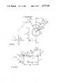
- FIG. 1is an axonometric view of a robot incorporating the recharge docking system according to this invention
- FIG. 2is a simplified exploded view with parts removed of the robot of FIG. 1;
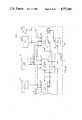
- FIG. 3is a block diagram of the electronic modules included in the robot of FIGS. 1 and 2;
- FIG. 4Ais a schematic top plan view of the relationship between the head and the body to each other and relative to the environment;
- FIG. 4Bis a schematic top plan view of alignment between the head and the body using a position encoder
- FIG. 4Cis a schematic top plan view of the sign of angles in relation to the front of the robot.
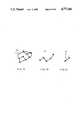
- FIG. 5Ais a schematic top plan view of the angles and distances between the robot, a predetermined node, and a beacon;
- FIG. 5Bis an elevational plan view of the robot and beacon of FIG. 5A relative to each other;
- FIG. 5Cis a schematic top plan view of the angles and distances between the robot, a selected path, and an offset beacon;
- FIG. 6is a schematic block diagram of the mobile module of FIG. 3;
- FIG. 7Ais a schematic diagram of a map of a number of nodes established in the environment.
- FIG. 7Bis a schematic diagram of a global navigation path to a goal node within the map of FIG. 7A;
- FIG. 7Cis a schematic diagram of local navigation between two nodes of the global path of FIG. 7B;
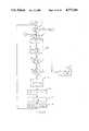
- FIG. 8Ais a schematic block diagram of position estimation
- FIG. 8Bis a flow chart of the arbiter of FIG. 8A;
- FIG. 9is a flow chart of the X-axis calibration of FIG. 8A.
- FIGS. 10A and 10Bare flow charts of end-path calibration of FIG. 8A;
- FIGS. 11A and 11Bare flow charts of body angle calibration of FIG. 8A;
- FIG. 12Ais a schematic block diagram of local navigation
- FIG. 12Bis a flow chart of the arbiter of FIG. 12A;
- FIG. 13is a flow chart of the beacon tracking system of FIG. 12A;
- FIG. 14is a schematic top plan view of a robot navigating around an obstacle
- FIGS. 15A-15Care flow charts of the obstacle avoider of FIG. 12A;
- FIG. 16is a schematic top plan view of the determination of avoidance distance in a corridor
- FIG. 17is a schematic top plan view of the computation of side swipe angle around an object
- FIG. 18is a flow chart of the path follower system of FIG. 12A;
- FIG. 19is a schematic block diagram of the interrelation between the map, global navigation and local navigation;
- FIG. 20is a flow chart of the planner of FIG. 19;
- FIG. 21is a flow chart of the executive of FIG. 19;
- FIG. 22is a schematic of entry nodes and base nodes for two recharging stations according to this invention.
- FIG. 23is a flow chart of docking operation
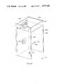
- FIG. 24is an axonometric view of a recharging base station according to this invention.
- FIG. 25Ais an enlarged view of a portion of the charging unit including the retractable arm used in the base station of FIG. 24;
- FIG. 25Bis a detailed plan view of the contact yoke of the retractable arm of FIG. 25A;
- FIG. 26is a schematic diagram showing the operation of the retractable arm and limit switches of FIGS. 24 and 25;
- FIG. 27is a block diagram of the status module and battery monitor circuit according to this invention.
- FIG. 28is a more detailed schematic diagram of the voltage and current monitor of FIG. 27;
- FIG. 29is a flow chart of the software used in the microprocessor of FIG. 27 to control the voltage and current monitor;
- FIG. 30is a block diagram of position locating including beacon sensors and the beacon electronic module
- FIG. 31is an illustration of the optical burst output of the beacons of FIG. 30;
- FIG. 32is an enlarged detail of a single burst of FIG. 31;
- FIG. 33is a more detailed block diagram of a beacon shown in FIG. 30;
- FIG. 34is a more detailed block diagram of an eye shown in FIG. 30;
- FIG. 35is a more detailed block diagram of the beacon STD-bus interface of FIG. 30;
- FIGS. 36A and Bare flow charts of the software utilized in the microprocessor of FIG. 30.
- FIG. 37is a schematic of the photodiode of FIG. 34.
- FIG. 1a vehicle, robot 10 according to this invention including a head section 12 and a base 14 movable on three wheels, only two of which, 16, 18, are visible.
- the wheelsare mounted in three steerable trucks, only two of which, 20 and 22, are visible.
- ultrasonic transducers 24such as the electrostatic transducers of the Sell type available from Polaroid equally spaced at fifteen degrees around the periphery of base 14.
- One of transducers 24, such as transducer 24ais designated as sensor zero; its azimuthal heading is utilized as described below.
- transducer 24ais designated as sensor zero; its azimuthal heading is utilized as described below.
- Head section 12is mounted to base 14 and rotates with respect to base 14 about a central vertical axis. Head section 12 carries an RF antenna 65 for sending and receiving communication signals to a base location or guard station. Head section 14 also includes an infrared sensor 60 for sensing radiation in the near infrared region, e.g.
- nm880 nm, such as emitted from LED 62 of beacon 64, one or more of which are mounted on the walls in the space to be protected by robot 10 to assist in locating and directing robot 10 in the area in which it is to roam.
- An ultrasonic transducer 66similar to one of the transducers 24 used for maneuvering and avoidance may be provided for ranging.
- a passive infrared sensor 68similar to sensors 28 and 30.
- a microwave transmission and reception antenna 70 and a TV camera 72which may be turned on when an apparent intrusion has occurred; these are also included in head 12.
- FIG. 2includes a main chassis 80 which carries three batteries 82 such as globe 12V 80AH gel cells, only one of which is shown. When fully charged they will operate the robot for twelve hours or more.
- batteries 82such as globe 12V 80AH gel cells, only one of which is shown. When fully charged they will operate the robot for twelve hours or more.
- Robot 10is provided with a synchro-drive locomotion system 83.
- the wheelsare steered simultaneously and driven simultaneously.
- base 14optimally maintains an azimuthal angle which is fixed in space and serves as the basic reference of the robot to the outside world.
- Trucks 20 and 22, with wheels 16 and 18 respectively,are suspended from chassis 80.
- Each truck as indicated at truck 20includes a right-angle drive 84 which receives input from vertical drive shaft 86 and provides output on horizontal drive shaft 88 to operate pulley 90.
- Pulley 90through belt 92 drives pulley 94 attached to the axle of wheel 16.
- Vertical drive shaft 86 and counterpart drive shafts 96 and 98are driven by their respective sprockets or pulleys 100, 102, 104 which in turn are driven by endless belt 106 powered by the pulley 107 on output shaft 108 of drive motor 110 mounted beneath chassis 80.
- An encoder 111 mounted with motor 110monitors the velocity of the robot.
- An idler wheel 112is provided to maintain proper tension on belt 106.
- Three additional shaftsare driven by a second set of pulleys or sprockets 120, 122, 124 engaged with drive belt 126 powered by sprocket 128 driven by steering motor 130 mounted beneath chassis 80.
- Idler pulley 131is used to maintain tension on belt 126.
- An encoder 132is associated with steering motor 130 to provide outputs indicative of the steering position.
- the steering motor shaftis connected through pulley 128 to extension shaft 134, the top of which is provided with a flange 136 with a plurality of mounting holes 138.
- Electronic chassis 140is mounted by means of screws 142 of three shorter standoffs 144. Three holes 146 in electronic chassis 140 accommodate the pass-through of longer standoffs 148, which mount neck 26 by means of screws 150. Electronic chassis 140 contains all of the electronic circuit boards and components such as indicated as items 152 that are contained in the base 14, including the status module described infra.
- extension shaft 134 and flange 136 and the associated structureare accommodated by the central hole 160 in electronic chassis 140 and the opening in neck 26 so that the head plate 170 may be mounted by means of screws 172 to threaded holes 138 in flange 136.
- the entire headrotates in synchronism with the trucks and wheels as they are steered by steering motor 130.
- Arrow 171represents the frontal, forward-facing orientation of head 12.
- housings 192, 194, and 196In addition to the primary microwave sensor 70 there are three additional microwave sensors only one of which, 190, is visible spaced at ninety degrees about head plate 170 mounted in housings 192, 194, and 196.
- One or more additional ultrasonic sensorscan also be mounted in head 12, e.g., ultrasonic sensor 195 on housing 192.
- Housing 194faces directly to the back of the head as opposed to primary microwave sensor 70 which faces front. Housing 194 also contains a second infrared sensor, not visible, which is the same as infrared sensor 68.
- Head 12also contains internal reference sensors.
- Inclinometer 197such as the Accustar clinometer sensor available from Sperry Corp., is mounted on the rear portion of external sensor housing 199. Its use in X-axis calibration is described below.
- Cover 200protects the electronics on head plate 170. All of the electrical interconnections between head 12 and base 14 are made through slip rings contained in slip ring unit 202 mounted about extension shaft 134 in base 14.
- Head 12includes three electronic portions: beacon module 210, head ultrasonic module 212, and intrusion detection module 214.
- Beacon module 210responds to the head IR sensor 60 to determine what angle the beacon 64 is with respect to the robot. That angle is fed on bus 216 through the slip ring unit 202 to the main CPU 218. Beacon module 210 is also responsive to inclinometer 197.
- Head ultrasonic module 212responds to ultrasonic transducer 66 to provide ranging information on bus 216 to CPU 218.
- Intruder detection module 214responds to the four microwave sensors such as sensors 70, 190, and the two IR sensors such as sensor 68, to provide indications as of yet unconfirmed intrusion events. These events are processed by the alarm confirmation unit 220 in CPU 218 to determine whether a true confirmed intrusion has occurred.
- status module 222responds to the six infrared sensors 28-38 to provide an indication of an intrusion. Status module 222 may also monitor fire and smoke detectors, diagnostic sensors throughout the robot such as inclinometer 197, as well as chemical and odor detectors and other similar sensors.
- Mobile module 224operates and monitors the action of drive motor 110 and steering motor 130. The twenty-four ultrasonic transducers 24 provide an input to the body of ultrasonic module 226, which provide digital range information for the robot.
- body 14contains CPU 218, which in addition to the alarm confirmation unit 220 also interconnects with a floppy disk controller, a two-channel serial I/O board, and a reset board which receives inputs from a pushbutton reset and CPU 218 and provides as outputs ultrasonic resets, motor resets, status resets, beacon resets, I/O module resets and head ultra resets.
- CPU 218also receives inputs from RF antenna 65 through RF circuit 240.
- FIG. 4ASeveral notations describe the orientation of head 12 to body 14, as shown in FIG. 4A.
- Arrow 300represents its front, which faces the direction of travel, shown as front arrow 171 in FIG. 2.
- the azimuthal orientation of body 14, FIG. 4Ais represented by point 302, hereinafter referred to as sensor zero.
- Sensor zerois a designated, fixed point on body 14 itself, e.g., sensor 24a, FIG. 2.
- the angle between head front 300 and sensor zerois theta D .
- the azimuthal angular distance from global zero to sensor zerois represented by theta B ; arrows 304 represent the designated orientation for the surrounding environment.
- Head 12is realigned with base 14 using position sensor 135 and magnetic detent 306 on shaft 134 as shown in FIG. 4B. This is accomplished at designated homing nodes by rotating head 12, that is, by pivoting the three steerable trucks, about its vertical axis such that magnetic detent 306 is brought into alignment with position sensor 135 of base 14. The head direction angle theta D is then set to zero; this and other operational parameters of the robot are maintained in updatable memory, hereinafter referred to as the blackboard, in CPU 218, FIG. 3.
- Angles in the clockwise direction, indicated by arrow 291 between object 290 and object 292,are positive in value.
- Angles in the counterclockwise direction, shown by arrow 293 toward object 294,are negative.
- the position and orientation of robot 10 relative to beacon 64ais shown in FIG. 5A.
- Theta HAis the actual horizontal angle, that is, the azimuthal angle, between head front 300 and beacon 64a.
- Beacon 64aas a 30° transmitter beam width, indicated by arrow 303, which is detected by sensor 60, FIGS. 1 and 2, within its 22° field of view.
- the expected horizontal angle, theta HEis zero when robot is properly following path 308 toward wall 301.
- Horizontal deviation from path 308is designated by the variable y, here shown by arrow 310.
- the orientation of path 308is represented by angle theta P , which is 180° in relation to coordinate arrows 304.
- Dashed line 312parallels path 308.
- the angular deviation from the direction of path 308 to front 300is represented by head-path angle theta M .
- Sensor zero path angle theta SZis the angle from the path to sensor zero 302.
- Head direction angle theta Dis equal to the sensor zero path angle theta SZ subtracted from head-path angle theta M .
- Angle theta SZis equal to path angle theta P minus body angle theta B .
- body angle theta Bserves as the basic reference for robot 10 to the outside world.
- the actual direction of an intruder, a fire or a pathis determined for the robot in relation to sensor zero whose heading is updated by body angle theta B .
- Body angle calibrationthat is, the updating of the angular orientation between sensor zero and global zero, can be conducted at any place along path 308. Calibration of the distance travelled in the X direction, shown by arrow 314, must be conducted at a predetermined location such as node 316. As shown in FIG. 5B, the vertical angle, that is, the altitude angle, between beacon sensor 60 and LED 62a of beacon 64a is classified as actual vertical angle theta VA . This is obtained while robot 10 is distance f A from wall 301. The expected vertical angle theta VE is learned by initially placing robot 10 at node 316 to measure the angle. Inclinometer 197, FIG. 2, is utilized to correct for unevenness in terrain.
- the expected distance f Eis measured from node 316 to wall 301 and can be used instead of expected vertical angle theta VE .
- the vertical distance between the height of beacon sensor 60 and LED 62amust be measured, represented by vertical distance e and shown by arrow 318.
- the robot's radius ris added to the trigonometric calculations.
- the actual distance between robot 10 and wall 301can also be measured by head ultrasonic sensor 66 within its 15° field of view. This distance measurement is denoted as horizontal distance R HA and is shown by dashed arrow 320.
- Geometric parameters describing the location of robot 10 along the path and its orientation relative to an offset beaconare shown in FIG. 5C.
- the path distance X pis represented by line 321 between the start node 320 and end node 322.
- Line 324represents the distance travelled, X M
- line 326designates the remaining distance to travel, X p -X m .
- beacon 64bIf the reference to be observed by robot 10 such as beacon 64b, is not directly aligned with path 308a, the angle between beacon 64b and path 308a is denoted by offset angle theta off .
- Head horizontal angle theta HArepresents the difference in orientation between head front 300 and beacon 64b.
- Mobile module 224includes motor controller 330, which controls drive motor 110 and steering motor 130.
- Distance travelledis determined by encoder 111 which provides this information to X-Y positioner 332.
- steering encoder 132provides change in orientation information to positioner 332, which accordingly outputs path distance X M , path deviation Y M , and head orientation theta M , which denotes the angle of the head to the path.
- Encoders 111, 132also provide feedback to motor controller 330.
- Map 338FIG. 7A
- Map 338includes selected nodes 340 which have a known distance and angle among each other.
- the robottravels toward successive goal nodes. For example, if the robot is at node 4, the starting node, the robot can be directed to visit goal node 7.
- the paths required to accomplish thisare designated in FIG. 7B as the global path 342.
- Global path 342designates consecutive navigation nodes, and a list of paths between these nodes.
- the robotmust change headings, recalibrate estimated position, and head towards the next node.
- Travel along the particular pathis represented by path 344, FIG. 7C.
- Local navigation along path 344moves the robot from node 4 to node 5.
- FIGS. 7A-7Csimply represent navigable paths through the environment and do not actually describe the surrounding environment. This system requires much less information than other systems utilizing more complicated techniques such as geometric modeling of the environment.
- the predetermined map informationalso includes a number of characteristics for each path. These include the distance of the path and its angle, theta P , in relation to global zero.
- the path informationmay also include the width of the path, and, if a beacon is disposed at the end of the path, the beacon code, distance f, height e, and expected vertical angle theta VE .
- the intensity of the beaconcan be monitored to confirm proper operation of the beacon if it is an active beacon; expected intensity of passive beacons such as reflectors or bar codes are not required.
- One or more position calibration techniquescan be specified, such as X-axis calibration, ultrasonic end-path calibration, and body-angle calibration.
- Robot 10uses one or more position calibration systems 399 to estimate its position as shown in FIG. 8A.
- the position calibration systems 399are located within CPU 218 and draw upon several modules.
- X-axis calibration system 400obtains the vertical deviation phi i from inclinometer 197, information from map 402, and actual vertical angle theta VA from beacon module 210.
- End-path calibration system 404provides an alternate technique of determining the difference in travel along the X-axis and determining adjustments to body angle theta B .
- End-path calibration system 404draws upon map 402 and ultrasonic range data from module 212.
- Body-angle calibration system 406corrects for accumulated error in orientation due to such factors as drift and precession of base 14.
- System 406is responsive to map 402, beacon data including theta HA from beacon module 210 and data from mobile module 224 representing present estimated position and head orientation.
- arbiter 408updates blackboard 410 which maintains current status information for robot 10 including its actual position.
- Initializer 411supplies initial values to blackboard 410, such as zeros generated for body angle theta B .
- Arbiter 408provides corrected Y M and theta M values to X-Y positioner 332, FIG. 6 while the robot is moving and while stationary provides X M , Y M and theta M corrections to motor controller 330 which are implemented as directed.
- Arbiter 408uses end-path calibration from system 404 when nearing the end of the path. Body-angle calibration from system 406 is examined along the path and at specified nodes. X-axis calibration from system 400 is obtained only at selected nodes.
- arbiter 408The operation of arbiter 408 is shown in FIG. 8B.
- Calibration systemscontinually output calibration values or "NO VALUE" but are sampled to obtain their estimations of position only if enabled from map 402 for the particular path or node the robot presently occupies.
- Calibration of body angle, X-axis, and end-path positionare successively accessed, steps 412, 414 and 416, respectively.
- the arbiterdecides whether to relinquish control of the robot when a calibration system requests motor control.
- step 412the arbiter observes, step 418, whether calibration system 406 has requested control by setting its control flag. If it has, control is provided, step 420, unless an external override command (not shown) is present.
- the arbiterwaits for body angle calibration to be completed, step 422, and then examines whether the output calibration data is other than "NO VALUE". Valid data is entered into blackboard 410 via step 426 while the operation proceeds directly to step 414 if the data are NO VALUE.
- step 418examination of the output data is immediately made, step 424.
- step 424the outputs of X-axis calibration and end-path calibration are obtained, as represented by loops 430 and 432, respectively.
- steps 434 and 436control remains with the respective calibration systems until the difference between the actual and expected position of the robot along the path becomes zero.
- X-axis calibration system 400The operation of X-axis calibration system 400 is shown in FIG. 9. If the robot is stopped, step 440, a distance correction of delta X equal to NO VALUE is provided, step 442. When the robot is in a fixed position the X-axis calibration flag is raised, step 444, and the calibration system waits until control is received, step 446. The beacon is located, step 448, and inclinometer 197 is read until motion of the robot settles, step 450. Once stable, the final inclination reading, phi i is taken, as is the stable reading of vertical angle theta VA , step 452. Actual vertical angle theta VA is corrected by inclination phi i which has a positive or negative value depending whether robot 10 is inclined toward or away from the beacon, respectively, step 454.
- step 456The difference between the expected X distance and the actual X distance is obtained in step 456 as represented by the trigonometric formula ##EQU1## where delta X is the difference in position along the X-axis, theta VE is the expected vertical angle, theta VA the actual vertical angle, and e is the vertical elevation of the beacon as described in FIG. 5B.
- the value of delta Xis provided to motor controller 330 through arbiter 408, step 458.
- the robotmoves along distance X M by an amount equal to delta X, step 459.
- the operationcycles to step 440 and the robot is readjusted until a delta X of zero is resolved in step 456.
- delta Xcan be calculated using other methods, for example, where the expected horizontal distance between the robot and the beacon is substituted to calculate expected vertical angle theta VE .
- the latter parameteris preferred because it can be obtained empirically in such operations as map making by locating the robot at the node or other predetermined location and instructing it to observe the beacon to learn the vertical angle. This obviates the need for physically measuring the horizontal distance between the robot and the beacon.
- the operation of the end-path calibration systemcommences with reading of the head ultrasonic range R HA , step 460, FIG. 10A. If the actual range is greater than the expected range, supplied by map 402, an output of "delta X equals no value" is generated, steps 462, 463, respectively.
- step 464the end-path calibration flag is raised, step 464 and the calibration system waits until control is received, step 466.
- the calibration systemcommands that the drive motor halt, step 468, and commands head ultrasonic 66 of head 12, FIGS. 1 and 2, to take n ultrasonic readings along a selected arc, such as fifteen readings along a 30° arc, each reading two degrees apart from the others, step 470. The minimum distance is found in step 472.
- a direction perpendicular to the wallis computed, step 474, e.g., by using the angle which gave the minimum distance in step 472.
- the robotis commanded to turn to this perpendicular direction, step 476, FIG. 10B, after which delta theta B is set to theta turn , step 476.
- a final reading of the head ultrasonicsare taken to obtain distance R HA , step 478.
- the deviation in distance traveled along the X-axisis determined by the formula
- delta X and delta theta Bare output to motor controller 330 through arbiter 408, steps 480, 482, respectively.
- the position X M of the robotis adjusted by delta X, step 483.
- the end-path calibration systemcycles to step 460 to resume monitoring.
- the body angle calibration systemcorrects for accumulated error in orientation which is due to the drift or precession of base 14.
- Path deviation distance Y Moccurs during obstacle avoidance, for example, and changes in head orientation represented by theta M can be attributed to rotation of head 12 while tracking a beacon to correct for precession of the body.
- Body angle calibration system 406corrects and calibrates for each of these variables.
- the beacon horizontal angle theta HAis read, step 484, FIG. 11A.
- the operationfirst determines whether the robot is stopped at a node and, if it is, raises body angle calibration flag, step 488, FIG. 11B. Once control is received, step 490, the system determines whether the node is a homing node, step 492. If it is, the robot turns to face sensor zero, step 494 and direction angle theta D is set to zero. Otherwise, operation proceeds directly to step 496 where path direction theta P obtained from the map 402. The turn angle theta turn is set to the distance direction theta D subtracted from path orientation theta P , step 498.
- step 500Once turn angle theta turn is obtained, that value is output to motor controller 330, FIG. 6, step 500.
- the robotturns to face the expected beacon and hunts for the beacon, steps 502, 504, respectively.
- the final head orientation theta Mis recorded and operation proceeds to step 484, FIG. 11A, and beacon horiontal angle theta HA is read.
- the expected deviation distance Y M and the head direction theta Mare read from the mobile module, step 504.
- step 510If the beacon is in view and the robot is on course, meaning that the absolute values of horizontal orientation theta HA is less than 10° and deviation distance Y is less than one foot, calibration of body angle is obtained by determining the increment delta theta B as equal to the sum of theta M and theta HA , step 510. If either of steps 506 and step 508 are not satisfied, meaning that the robot has significantly deviated from the path, no value is output, step 512, and other calibration systems such as end-path calibration are initiated.
- Yis reset by setting delta Y to negative Y, step 514, and delta theta B and Y are provided to the arbiter 408, step 516.
- head angle theta Mis reset by setting it equal to minus horizontal angle theta HA , step 515, shown in phantom. Operation then returns to steps 486, 484 as described above.
- body angle calibrationinvolves reading the beacon horizontal angle theta HA , turning to face the beacon, setting delta theta B to theta HA , and outputting delta theta B .
- delta theta Bis initially set to zero and then incremented as needed by either the body angle calibration or end-path calibration systems.
- Position estimation system 399ensures that the robot is properly positioned and oriented.
- Navigation system 520FIG. 12A, accurately guides the robot along a path toward a destination while avoiding obstacles in the path.
- Navigation system 520provides a turn angle theta turn and a drive velocity V d .
- Obstacle avoider system 528, beacon tracker 522 and path follower 526continually output values for theta turn and V D .
- motor controller 330does not receive these values unless approved by arbiter 524.
- beacon tracker 522When a beacon is placed as a marker proximate to a destination, the output of beacon tracker 522 is directed by arbiter 524 to motor controller portion 330 of mobile module 224.
- Beacon tracker 522utilizes horizontal angle theta HA from beacon data 516 from beacon module 210, position data 518 from mobile module 224 as updated on blackboard 410, and information from map 402. If the beacon is not within a certain azimuthal angle from the head orientation of the robot, or when no beacons are present, path follower 526 provides turn angle theta turn and the appropriate drive velocity V D . Path follower 526 performs dead reckoning utilizing position data 518 from mobile module 224 and expected data from map 402.
- Obstacle avoider 528utilizes ultrasonic data 530 from body ultrasonic module 226, head-path angle theta M , and data from map 402.
- the local navigation system 520is initialized at each node as described below.
- arbiter 524The operation of arbiter 524 is shown in FIG. 12B.
- the parameters X M , Y M , and theta Mare set to zero in the X-Y positioner 332.
- the drive motoris started, step 534, and the navigation system runs until X M is equal to or greater than the path distance X P and the absolute value of the deviation distance Y M is less than one foot, step 536. If these conditions are satisfied, local navigation is ended, step 538; otherwise, the navigation system continues to operate until the robot is brought quite close to the desired destination node.
- the final adjustment in positionis provided by position estimation system 399 as described above.
- step 540if avoider system 528 provides a turn angle of greater than zero, its output is provided to motor controller 330 of the mobile module, step 542. If the avoidance turn angle theta turn is zero, and the deviation distance Y M is less than one foot, theta turn and V D of beacon tracker system 522 are provided to mobile modul 224, steps 544 and 546, respectively. Otherwise, the dead reckoning of the path follower 526 is provided to mobile module 224, step 548.
- the operation of the beacon tracker systemis shown in FIG. 13.
- the horizontal theta HA and the distance traveled X Mare read from blackboard 410 and the path distance X P and known horizontal distance Y B of the beacon from the path are obtained from the map, steps 550 and 552, respectively.
- Horizontal distance Y Brepresents the offset distance of the beacon from the path as shown above in FIG. 5C.
- the offset angle theta offis determined in step 554 by the formula ##EQU2##
- the turn angle theta turnis equal to the sum of the horizontal angle theta HA and offset angle theta off , step 556.
- step 558the correct code must be present, step 558, or velocity V d and turn angle theta turn are set to no value, steps 560 and 562, respectively. If the correct code is present and the absolute value of the direction from the front of the head of the robot to the beacon is less than 11°, step 564, velocity V D is set to the patrol velocity V patrol and is provided as output along with the turn angle theta turn , steps 566 and 568, respectively. Operation then returns to step 550.
- the mobile modulecan accept new commands during execution of turns and changes of velocity, as directed by arbiter 524, to rapidly adjust its operation and provide for smoother turning and acceleration changes for the robot.
- FIG. 14Avoidance and path following of robot 10 in relation to obstacle 570 are shown in FIG. 14.
- Body ultrasound transducers 24, FIGS. 1 and 2provide a 25-foot range about robot 10 as indicated by circle 572.
- the range of the sensorsis ignored beyond maximum range R max , indicated by arrow 574, e.g. three feet.
- a limited sensor arc 575 of 135°, or 67.5° to either side of the desired direction headingis imposed.
- the field of view of the avoidertherefore utilizes the 15° field of view of the sensor oriented toward the desired direction, indicated by sector 576, and four sensors to either side of it, such as sensors in sectors 578, 580.
- front 300is oriented with sector 578, and not with sector 576, since face direction 300 is not oriented in the desired direction.
- Velocity field of view 577, 579is a 75° arc which utilizes the forward facing sensor and two sensors on each side of that sensor.
- While the desired pathis represented by line 582, the actual path traveled during object avoidance is illustrated by path 584.
- robot 10is returned to path 582 along route 586 using the path following system.
- the path following systemattempts to return robot 10 to path 582 within correction distance X corr , shown by line 588. Once returned to the path, robot 10 proceeds to follow a beacon, if present, or to continue path following.
- FIGS. 15A-15CThe operation of obstacle avoider system 528 according to this invention is shown in FIGS. 15A-15C.
- the range of each sensor ris examined for each sensor i, where i is the index of the sensors.
- the range of each sensor r iis monitored to determine when it is within range R max , step 590.
- step 592turn angle theta turn is set to zero and the drive velocity V d is set to the patrol velocity, until an obstacle comes within avoidance range.
- obstacle avoider system 528To prevent damage to the robot, obstacle avoider system 528 must take into account the width of the robot. As shown in FIG. 16, robot 10 has radius r and is navigating through passage 594 between walls 596, 598. Passage 594 has a width of 2w.
- the avoidance distance r avoidis the distance by which an object is avoided and is computed according to the formula
- a maximum avoid distance "max avoid”is set when r avoid exceeds max avoid, steps 602, 604, respectively, to prevent robot 10 from deviating excessively from its path during obstacle avoidance.
- a minimum clearance around objectscan be specified, such as a wide avoider clearance, e.g. eight inches, or a narrow avoider, e.g. three inches.
- Loop 606thresholds the range data within the avoidance viewing angle such that for each range element r i , step 608, the threshold set element t i is set to zero when r i is less than or equal to r avoid , and t i is set to one when r i is greater than r avoid , steps 610, 612, respectively.
- step 616the side-swipe angle theta ss is computed.
- side-swipe angle theta ssis the minimum angle which robot 10 must turn such that point P will miss obstacle 618. In other words, robot 10 must alter heading 620 to at least heading 622 to avoid collision.
- the side-swipe angleis computed according to the formula ##EQU3## The side-swipe angle is utilized, step 616, FIG. 15A, to compute the number of sectors by which the robot must avoid an object. In other words, neighboring sectors of a blocked sector must be set to zero.
- the zero-neighbor factoris computed by dividing the side-swipe angle theta ss by the beam width theta bw , step 618, and rounding upwards to a whole integer.
- the beam width theta bw of the ultrasound transducers of robot 10is 15°.
- a clear setis constructed in loop 620 by examining each thresholded range element t i and when it equals zero, step 622, its neighbors are zeroed such that the resulting clear set elements C i within Z sensor sectors of a blocked sector are set to zero, step 624.
- the sensor facing the direction of travelis computed in steps 628, 630.
- the sensor zero path angle theta szis the angle from the path heading to sensor zero and is determined by subtracting the body angle theta b from the path angle theta p .
- the integer number of the sensor facing the direction of travel, sensor S dis determined according to the formula ##EQU4## as shown in step 630.
- direction sensor S dSince direction sensor S d is blocked, the nearest open sensor which, when the robot heads in that direction, will enable the robot to clear the obstacle, is determined by hunting successively clockwise to counterclockwise and back again from direction sensor S d to find the clear sensor S c , step 632.
- the clear sensor S cis described as the non-zero element in the clear set nearest to the direction sensor S d in clear set C i . This can be determined according to the formula
- equation (7)successively generates the elements 0, 1, n-1, 2, n-2, 3, . . . , by which elements on either side of the desired sensor direction are alternately examined.
- the first non-zero clear set memberis selected as the clear sensor.
- the head direction angle theta dis calculated by subtracting the sensor zero angle theta sz from the head-path angle theta m , step 634.
- the index number of clear sensor S cis converted into degrees by multiplying it by beam width theta bw , from which is subtracted head direction angle theta d , step 636, to obtain theta turn , step 636.
- the velocityis determined within the velocity field of view 577, 579, FIG. 14, by determining the minimum range r min within the forward-facing field of view, that is, around head direction angle theta d , step 638.
- Minimum range r minis utilized in loop 640 to determine the drive velocity V d by dividing the minimum detected range r min by the maximum avoidance range R max and multiplying it by the patrol velocity, step 642.
- the patrol velocityis maintained, steps 644, 646, until R min drops below R max .
- the present distances X m , Y mare read from blackboard 410, step 650.
- the path distance X pis obtained from map 402 in step 652 and is compared to the distance actually travelled, X m , to ensure that the correction distance X corr will not bring the robot beyond the destination node.
- the correction distance X corris described above in relation to FIG. 14. From step 654, FIG. 18, the minimum elapsed distance along the X axis is set to correction distance X corr , step 656, unless the robot is close to the node as defined in step 658.
- the turn angle theta turnis computed according to the formula
- step 660As shown in step 660.
- the travel velocityis inversely proportional to the magnitude of turn angle theta turn as shown in step 662.
- the drive velocity and turn angleare then provided to arbiter 524, step 664, and operation returns to step 650.
- the output of beacon tracking system 522is granted priority over the output of path follower 526 so that the robot resumes tracking the beacon, if present, once it is back on the path.
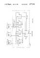
- Global navigation system 670includes planner 672 and executive 674.
- Planner 672is responsive to map 676, which contains the expected position estimation data, described above in relation to FIGS. 7A-7C, and other data such as the path type.
- a pathcan be designated as a avoidance path where objects are known to be present, a dead-reckoning path where no beacon is present, or a beacon tracking path where a navigation beacon is provided.
- the pathcan also be identified as a docking path which returns the robot to a recharge station, or as an intrusion detection path where intrusion detection is to be performed.
- Other informationcan be specified such as the patrol velocity or whether a narrow or wide avoidance clearance is required.
- Operator 678represents a guard or other personnel which provide commands to planner 672 such as the start node, the goal list, or a command to go to a particular node. Operator 678 can command the robot to resume patrol or to return to the charge station.
- Planner 672prepares a path list comprising the executive nodes to visit between each goal node and provides this list to executive 674.
- Executive 674identifies the path direction and destination node when a current node is occupied, at which point local navigation 520 operates until the destination node is reached. Local navigation 520 relies upon the blackboard for current status information.
- the travel of the robotis interrupted by battery status 680, which monitors voltage to determine when the batteries have discharged below a predetermined amount. Recharge current is monitored while the robot is docked to determine when the batteries are sufficiently charged.
- Executive 674notifies planner 672 on line 682 when the path list is complete or when battery status 680 indicates that the batteries have discharged below a certain level. Planner 672 then calculates the return path to the nearest charge station.
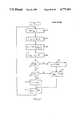
- planner 672The operation of planner 672 is shown in FIG. 20.
- the current nodeis set to the start node, step 690, and loop 692 computes the shortest path from the current node to the goal node for each node in the goal list.
- the shortest pathis computed using Djikstra's algorithm, such as described in Aho, Hopcroft and Ullman, Data Structures and Algorithms (1983), page 205.
- the path list for those nodesis thereby constructed, step 694, unless the path is not possible, step 696, in which case the next goal node is requested, step 698, and an alternative destination planned.
- step 700For each path list, the executive 674 is summoned, step 700, and is provided with the path list.
- the executivehas completed that path list, step 702, the next goal is requested, step 698.
- step 710The operation of executive 674 is shown in FIG. 21.
- Local navigation 520is summoned, step 710, and the path information is provided to it, step 712.
- step 714Once local navigation has ended, step 714, and the destination node becomes the current node, the current node is updated, step 716, to identify it as the former destination node.
- step 718the executive instructs the planner while at the node to return the robot to the nearest charge station, step 720. If the battery voltage is merely low, step 722, e.g. 11.1 volts, the operator is warned, step 724, and the robot resumes patrol. Executive 674 proceeds through the path list, step 726, until it is completed.
- Map 676can be generated by an operator who escorts the robot from node to node in a premises to be patrolled.
- the operatordirects the robot to the node, a beacon is placed at the next node, and the robot is informed of the code for that distant beacon.
- the robotthen scans, finds the beacon, and proceeds toward the beacon. If a beacon is not placed at the next node, the operator again directs the robot where to travel.
- the robotwhen at the next node records such information as the vertical angle to the beacon theta VA , the distance to a wall R HA , and the path distance X p is set to the actual distance travelled, X m .
- the nodemay be named by the operator so that he can designate it as a goal node in the future.
- the operatorplaces another beacon at the next node, and the process is continued until the robot has mapped its area of patrol.
- the robotfinds each node by operator designation or by beacons previously placed at the node.
- the robotthen defines nodes by noting the angle and distance to and from the beacon, by uniquely identifying the beacon, or by other landmarks including passive beacons such as reflectors and bar codes.
- the robotcan also define a node in terms of grid-based or segment-based geometric modeling.
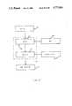
- Charge stations 730, 732 according to this inventionare shown in FIG. 22. Entry nodes 734, 736 are used to calibrate the position of the robot before entering base nodes 738, 740, respectively.
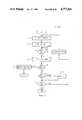
- the entry and base nodesare used as follows, FIGS. 22 and 23.
- the robotAfter navigating from navigation node 742 to entry node 734 for charge station 730, the robot performs X axis calibration, steps 744, 746, respectively.
- Beacon 749is used as a reference during X calibration. If the base beacon is off the path, such as beacon 750 of charge station 730, the robot turns to face the base beacon, steps 752, 754.
- a second X axis calibrationis then performed, step 756, using beacon 750 for reference.
- the obstacle avoidance systemis then disabled, step 760, and the robot dead-reckons to the base charge node and docks, step 762.
- the headis spun 180°, step 764, so that the robot faces the door of the charge station, and the charging current is monitored until the trickle charge drops below a minimum, step 766.
- the robotutilizes beacon tracking to exit the charge station and resumes patrol, steps 768, 770, respectively.
- Base station 800for docking and recharging robot 10.
- Base station 800includes two side walls 802 and 804, back wall 806, top 808, and front panel 810.
- Beacon 64 or a similar oneis mounted on back wall 806.
- Navigational nodessuch as the entrance node 812 and the base node 814 are positions located in front of station 800 and within it.
- Mounted on wall 804is a microswitch 816 or a similar device having elongated arm 819, which extends into the middle of base station 800 and is tripped by the entrance of a robot.
- a charging unit 828, shown in FIG. 25A, and its retractable armextend through elongate rectangular hole 820 in the back 806 of base station 800.
- Retractable arm mechanism 830, FIG. 25Aincludes a scissor mechanism 832 with its upper and lower ends 834, 836 connected to threaded bushings 839 and 840, respectively, which are driven together toward the center to extend the arm, or apart away from the center to retract the arm by shaft 842, which has oppositely threaded portions 844 and 846.
- Shaft 842is driven through coupling 848 by gear drive 850, which is in turn driven by motor 852.
- gear drive 850which is in turn driven by motor 852.
- Bracket 858is fixed to the front of scissor arm 832 and includes a shaft 860 held in place by a pair of springs 862 and 864. Shaft 860 pivotally mounts contact yoke 866 between washers 868 and 870.
- bracket 858is fastened to scissor arm 832 by means of a yoke 866 which is held with shoulder screws.
- Contact yoke 866is generally centered by means of springs 872 and 874 but is easily pivoted to align itself with conductor bands 50, 52 on robot 10.
- Brushes 876 and 878are arranged one on top of the other on the right side of yoke 866, and brushes 880 and 882 (not shown) on the left side of yoke 866.
- Each of the brusheshas associated with it a brush assembly 884 which includes a cap 886, cylinder 888, and spring 890 for biasing brush 880 outwardly. Also mounted on yoke 866 is a docking microswitch 890 which senses when the robot has engaged the contacts on yoke 866.
- the logic circuit that controls the operation of switches 854, 856, 890 and 816 in conjunction with motor 852 that extends and retracts scissor arm 832 of charging mechanism 830is shown in detail in FIG. 26, where the retract input to motor 852 is delivered from OR gate 892 and the extend input to motor 852 is delivered from AND gate 894 through inverter 896.
- Table IA truth table showing the pertinent conditions for the operation of the circuit is shown in Table I:
- the truth tablesimply states that if the robot is in the recharge station and arm 832 is not out all the way, and the charging contacts have not engaged the robot, then the arm will extend. Conversely, the arm will retract if the robot is out of the house and the arm has not yet retracted all the way in.
- the charging circuitis on when the docking switch 890 is tripped. When dock switch 890 is tripped, a signal is sent on line 897 to enable charger circuit 898 to energize brush contacts 876, 878, 880 and 882 via line 899.
- the charging armis shown as a sensor arm with a pivotable yoke, any other approaches may be used, for example a telescoping arm with a plug.
- the batteriesare constantly monitored by voltage and current monitor 900, FIG. 27, whose output is delivered to status module 222, which includes a signal conditioner 902, A/D converter 904, and a microprocessor such as a Z80, 906.
- the voltage and current monitor 900includes three pairs of lines 908, 910 and 912 from the positive and negative outputs of each the batteries 82, 83 and 85, respectively, FIG. 28. The full thirty-six volts of these three twelve-volt batteries is applied across the full robot load 914.
- a fourth output, a pair of lines 916 which sense the current through resistor 918,are also provided at the output of monitor 900 to the signal conditioner 902.
- microprocessor 906When the signals from those four sets of lines are received in microprocessor 906, it executes a software routine in which it obtains the A/D data in step 920, then multiplexes the input channels on the A/D board in 922. Multiplexing is done because in addition to the four sets of inputs from voltage and current monitor 900 there are a number of other circuits whose outputs are delivered to status module 222 for monitoring and processing. After multiplexing the A/D outputs are obtained in step 924 and they are scaled in step 926 by microprocessor 906. Finally, the values are reported to CPU 218, which then applies the routines as previously explained to stop the robot at the next node, determine the shortest path from that node back to the base station, and execute those travel directions to dock the robot with the charging unit at the base station.
- Position locating system 1350includes one or more beacon transmitters 64, 64a, 64b, each having an infrared source 62, 62a, 62b. Also included is an infrared sensor 60 sensitive to the infrared radiation emitted by source 62, and associated with sensor 60 is an eye circuit 1352 whose output is provided on bus 1354. Bus 1354 interconnects with beacon STD-bus interface 1356 in beacon module 210. Interface 1356 communicates with microprocessor 1358 over STD bus 1360. Microprocessor 1358 may be a Z80 and it communicates directly with CPU 218, which may be a 68000.
- Beacon transmitter 64provides an optical burst 1362 of coded signals every 15.6 milliseconds, FIG. 31. Each burst, as shown in greater detail in FIG. 32, has a total burst time of 244 microseconds which defines an eight-bit word, each bit being 30.5 microseconds wide. The first bit is a start bit; the next seven bits are code bits and represent 128 different possible codes. Each code can uniquely identify a single beacon, so that with this simple arrangement one hundred twenty-eight different beacons can be uniquely identified; that is, when the infrared source is seen that is considered a logic one. When the infrared source, which may be a light-emitting diode or LED, is off, then the signal is low and is considered a logic zero.
- the infrared sourcewhich may be a light-emitting diode or LED
- the signals shown in FIGS. 31 and 32are generated in beacon transmitter 64 by an oscillator 1364, FIG. 33, which runs continuously at 32.768 KHz. Its output is delivered directly to a register in code generator 1366. Its output is also delivered to a counter 1368, module 512, which divides the 32.768 KHz signal to provide the time period shown in FIGS. 31 and 32. That is, with every 64th pulse (or every 15.6 ms) a burst occurs of eight bits. Eight bits are set to one or zero to produce the unique code for a particular beacon by the setting of the code select keys 1370. When one of the keys 1370 is toggled to ground, the associated stage of the register in 1366 is grounded, thereby placing a logic one in that bit position. Switches that are left toggled to high level voltage produce a logic zero in the associated stage. The patterns of ones and zeros modulate the infrared radiation produced by LED 62 so that a coded signal is provided which uniquely defines the particular beacon.
- Sensor 60 in eye circuit 1352, FIG. 34is a multisector sensor such as a dual-axis lateral effect photodiode. It provides four separate outputs, each indicative of the infrared radiation incident on its particular sector. By analyzing the relative values of the radiation falling on the different sectors, a determination can be made as to the angle of the sensor to the emitting beacon. Each of the four sector outputs from photodiode 60 is fed to a different channel 1372, 1374, 1376, 1378. Each channel includes an amplifier 380, high-pass filters 1382, voltage amplifiers 1384, and sample and hold circuits 1386.
- High-pass filters 1382pass the coded signal from beacon 64 but block 60-cycle and 120-cycle signals introduced by ambient light conditions; periodically on command from microprocessor 1358 a signal on sample and hold line 1388 causes sample and hold circuits 1386 to sample and hold the signal in each channel. Those signals are then multiplexed by analog multiplexer 1392 as directed by a command from microprocessor 1358 on line 1390. The signal from each channel is fed directly to the gain control of amplifier 1394. Finally, the output from each channel is fed to A/D converter 1398, where it stops unless a control signal on line 1400 from microprocessor 1358 requests the angle data signal on line 1402. Microprocessor 1358 also provides a select and enable signal on line 1404 to A/D converter 1398 to indicate the particular eye circuit 1352, 1352a, 1352b or 1352c which is currently being interrogated.
- one or more of the outputs from photodiode 60 after passing through amplifiers 1380are combined in an AC summer 1406 in order to maximize the signal which will be used to detect the identifying code.
- the signalis passed to clipper circuit 1408 which limits the output independent of the input amplitude.
- the signalis constituted by one or more coded pulses riding on an envelope of sixty or one hundred twenty cycle noise.
- Differentiator circuit 1414is therefore used to detect only the transitions of the pulses; thus, for every positive-going transition a positive spike appears at the output of differentiator 1414 and for every negative-going transition a negative spike occurs at the output of differentiator 1414.
- the positive-going spikespass through amplifier 1416 and set flip-flop 1418 to define the beginning of a pulse.
- Negative-going spikes passing through amplifier 1420reset flip-flop 1418 and define the end of the pulse. In this way the pulses and the received coded signal are reconstituted one at a time to construct the code data signal on line 1422.
- the output of flip-flop 1418may again be switched to indicate which one of the eye circuits 1352, 1352a, 1352b or 1352c is currently being monitored.
- the angle data signal on line 1402, FIG. 35is fed directly through MUX 1424 in beacon STD-bus interface 1356 to STD-bus 1360.
- the code data signalis fed from MUX 1424 to code verifier circuit 1426. After it is verified it is submitted to a converter 1428 where it is changed from a serial signal to a parallel signal and then provided to STD-bus 1360.
- Code verifier circuit 1426may utilize any of a number of techniques for verifying the authenticity of an incoming code. For example, the incoming signal may be sampled at fixed times following a start pulse when pulse transitions would normally be expected in a valid signal. If the transitions occur within narrow windows at the expected times, they are treated as valid code; otherwise they are rejected.
- the code statusis provided on line 1430 to STD-bus 1360.
- step 1440Under software control, operation may begin with a signal from CPU 218 in step 1440, FIGS. 36A, B, with the command "Get Eye Daa".
- microprocessor 1358receives that signal it selects a particular eye in step 1442.
- the A/D converteris then commanded to start the conversion in step 1446 and the code data is obtained on line 1422 in step 1448.
- step 1450if the code data is bad the cycle starts again with the beginning of a new conversion in step 1446. If the code is good then the angle information is used and the next step 1452 provides the azimuth angle and the altitude angle and the code in step 1454 to microprocessor 1358.
- the angle datais converted to the azimuth angle and the altitude angle and combined with the code and directed to CPU 218.
- the azimuth angleneeds no further processing.
- the altitude angle and codeare delivered to CPU 218, which then retrieves the height H of the identified beacon in step 1456; height H can be unique for that beacon, or all beacons can be placed at the same height. That height is used to calculate the distance D to the beacon by dividing the height by triangulation, e.g., the tangent of the altitude angle in step 1458. Then the distance and direction of the robot versus the beacon is output in step 1460.
- step 1454, FIG. 28Aof the azimuth angle and the altitude angle from the angle data signal is accomplished by determining the X position and the Y position from the dual axis lateral effect photodiode of FIG. 34 shown in more detail in FIG. 37.
- the X positionis calculated according to the expression:
- A+C and B+Drespectively normalizes the signal to reduce its dependence on the incident light level.
- the anglesare those determined by the expression: ##EQU5## where K is a constsant dependent on the size of the detector and focal length of the light gathering lens if on is used:
- Dis the diameter of the detector and F 1 is the focal length of the lens o.
Landscapes
- Engineering & Computer Science (AREA)
- Physics & Mathematics (AREA)
- Radar, Positioning & Navigation (AREA)
- Remote Sensing (AREA)
- Aviation & Aerospace Engineering (AREA)
- General Physics & Mathematics (AREA)
- Automation & Control Theory (AREA)
- Electromagnetism (AREA)
- Power Engineering (AREA)
- Acoustics & Sound (AREA)
- Control Of Position, Course, Altitude, Or Attitude Of Moving Bodies (AREA)
- Manipulator (AREA)
Abstract
Description
This invention relates to an improved recharge docking system for a mobile robot, and more particularly to such a system for navigating back to a recharge station from anywhere on its patrol path.
The following applications, filed concurrently herewith, are incorporated herein by reference:
______________________________________ Inventors Title Serial No. ______________________________________ Maddox et al. Intrusion Detection System 864,032 Muller et al. Ultrasonic Ranging System 864,002 Benayad-Cherif Position Locating System 864,031 et al. for Vehicle Pavlak et al. Power-Up Sequencing Apparatus 864,590 Maddox et al. Beacon Proximity Detection 864,292 System for Vehicle Kadonoff et al. Orientation Adjustment System 864,450 and Robot Using Same Kadonoff et al. Obstacle Avoidance System 864,585 Kadonoff et al. Beacon Navigation System and 864,442 Method for Guiding a Vehicle ______________________________________
Presently, recharging the batteries of an autonomous mobile robot is a difficult and disruptive event. In one procedure a charger apparatus is simply wheeled out to the robot wherever it is or a power supply cable may be deployed to it. Another approach is to employ a beacon at the charge station so that the robot can home in on it. However, the homing action is only achievable when the need for a charge occurs when the robot is in line of sight of the beacon on the recharge station. Even in those cases where the robot can find its way back by line of sight beacon, it is still often necessary for it to be manually connected with the charger apparatus.
It is therefore an object of this invention to provide an improved recharging docking system for a mobile robot.
It is a further object of this invention to provide such a system which enables the robot to return to the recharge station whenever its batteries are low.
It is a further object of this invention to provide such a system which enables the robot to return to the recharge station even when it is not in line of sight of a beacon at the recharge station.
It is a further object of this invention to provide such a system which automatically docks the robot and connects the batteries to a charging circuit.
Yet another object of this invention is to provide such a system which automatically undocks the robot and returns it to its patrol.
This invention features a recharge docking system for a battery-powered mobile robot which navigates from node to node. There are means for sensing when the battery charge is below a predetermined level and means responsive to that means for sensing for halting the travel of the robot at the next navigation node when the battery voltage is below that predetermined level. There are also means for independently determining a path from the next node back to a base node, and means at the base node for charging the batteries of the robot.
In a preferred embodiment, the means for charging includes a base station for receiving the robot at the base node, and a charging unit. A charging unit may include a retractable arm for engaging a charging contact on the robot. A charging unit may further include means responsive to the presence of the robot at the base station for extending the retractable arm to engage a charging contact on the robot. The charging unit may also include means responsive to the engagement of the arm with the robot to cease further extension of the arm. There may also be limit means for detecting when the arm is in the fully extended and in the fully retracted position.
In another embodiment, the means for sensing includes means for indicating when the battery charge reaches a second predetermined level which is somewhat higher than the first predetermined level, and the system further includes means, responsive to the means for indicating, for providing a warning to an operator when the second predetermined level is reached. The means for determining includes means for selecting the shortest path to the base node.
Other objects, features and advantages will occur from the following description of a preferred embodiment and the accompanying drawings, in which:
FIG. 1 is an axonometric view of a robot incorporating the recharge docking system according to this invention;
FIG. 2 is a simplified exploded view with parts removed of the robot of FIG. 1;
FIG. 3 is a block diagram of the electronic modules included in the robot of FIGS. 1 and 2;
FIG. 4A is a schematic top plan view of the relationship between the head and the body to each other and relative to the environment;
FIG. 4B is a schematic top plan view of alignment between the head and the body using a position encoder;
FIG. 4C is a schematic top plan view of the sign of angles in relation to the front of the robot;
FIG. 5A is a schematic top plan view of the angles and distances between the robot, a predetermined node, and a beacon;
FIG. 5B is an elevational plan view of the robot and beacon of FIG. 5A relative to each other;
FIG. 5C is a schematic top plan view of the angles and distances between the robot, a selected path, and an offset beacon;
FIG. 6 is a schematic block diagram of the mobile module of FIG. 3;
FIG. 7A is a schematic diagram of a map of a number of nodes established in the environment;
FIG. 7B is a schematic diagram of a global navigation path to a goal node within the map of FIG. 7A;
FIG. 7C is a schematic diagram of local navigation between two nodes of the global path of FIG. 7B;
FIG. 8A is a schematic block diagram of position estimation;
FIG. 8B is a flow chart of the arbiter of FIG. 8A;
FIG. 9 is a flow chart of the X-axis calibration of FIG. 8A;
FIGS. 10A and 10B are flow charts of end-path calibration of FIG. 8A;
FIGS. 11A and 11B are flow charts of body angle calibration of FIG. 8A;
FIG. 12A is a schematic block diagram of local navigation;
FIG. 12B is a flow chart of the arbiter of FIG. 12A;
FIG. 13 is a flow chart of the beacon tracking system of FIG. 12A;
FIG. 14 is a schematic top plan view of a robot navigating around an obstacle;
FIGS. 15A-15C are flow charts of the obstacle avoider of FIG. 12A;
FIG. 16 is a schematic top plan view of the determination of avoidance distance in a corridor;
FIG. 17 is a schematic top plan view of the computation of side swipe angle around an object;
FIG. 18 is a flow chart of the path follower system of FIG. 12A;
FIG. 19 is a schematic block diagram of the interrelation between the map, global navigation and local navigation;
FIG. 20 is a flow chart of the planner of FIG. 19;
FIG. 21 is a flow chart of the executive of FIG. 19;
FIG. 22 is a schematic of entry nodes and base nodes for two recharging stations according to this invention;
FIG. 23 is a flow chart of docking operation;
FIG. 24 is an axonometric view of a recharging base station according to this invention;
FIG. 25A is an enlarged view of a portion of the charging unit including the retractable arm used in the base station of FIG. 24;
FIG. 25B is a detailed plan view of the contact yoke of the retractable arm of FIG. 25A;
FIG. 26 is a schematic diagram showing the operation of the retractable arm and limit switches of FIGS. 24 and 25;
FIG. 27 is a block diagram of the status module and battery monitor circuit according to this invention;
FIG. 28 is a more detailed schematic diagram of the voltage and current monitor of FIG. 27;
FIG. 29 is a flow chart of the software used in the microprocessor of FIG. 27 to control the voltage and current monitor;
FIG. 30 is a block diagram of position locating including beacon sensors and the beacon electronic module;
FIG. 31 is an illustration of the optical burst output of the beacons of FIG. 30;
FIG. 32 is an enlarged detail of a single burst of FIG. 31;
FIG. 33 is a more detailed block diagram of a beacon shown in FIG. 30;
FIG. 34 is a more detailed block diagram of an eye shown in FIG. 30;
FIG. 35 is a more detailed block diagram of the beacon STD-bus interface of FIG. 30;
FIGS. 36A and B are flow charts of the software utilized in the microprocessor of FIG. 30; and
FIG. 37 is a schematic of the photodiode of FIG. 34.
There is shown in FIG. 1 a vehicle,robot 10 according to this invention including ahead section 12 and a base 14 movable on three wheels, only two of which, 16, 18, are visible. The wheels are mounted in three steerable trucks, only two of which, 20 and 22, are visible. There are twenty-fourultrasonic transducers 24 such as the electrostatic transducers of the Sell type available from Polaroid equally spaced at fifteen degrees around the periphery ofbase 14. One oftransducers 24, such astransducer 24a, is designated as sensor zero; its azimuthal heading is utilized as described below. Above that on reducedneck 26 there are located six passiveinfrared motion detectors conductor bands Head section 12 is mounted tobase 14 and rotates with respect tobase 14 about a central vertical axis.Head section 12 carries anRF antenna 65 for sending and receiving communication signals to a base location or guard station.Head section 14 also includes aninfrared sensor 60 for sensing radiation in the near infrared region, e.g. 880 nm, such as emitted fromLED 62 ofbeacon 64, one or more of which are mounted on the walls in the space to be protected byrobot 10 to assist in locating and directingrobot 10 in the area in which it is to roam. Anultrasonic transducer 66 similar to one of thetransducers 24 used for maneuvering and avoidance may be provided for ranging. There is also provided a passiveinfrared sensor 68 similar tosensors reception antenna 70 and aTV camera 72 which may be turned on when an apparent intrusion has occurred; these are also included inhead 12.
Three additional shafts, only one of which, 99, is shown, concentric withshafts sprockets drive belt 126 powered by sprocket 128 driven by steeringmotor 130 mounted beneathchassis 80. Idler pulley 131 is used to maintain tension onbelt 126. Anencoder 132 is associated withsteering motor 130 to provide outputs indicative of the steering position. The steering motor shaft is connected through pulley 128 toextension shaft 134, the top of which is provided with aflange 136 with a plurality of mountingholes 138.Position sensor 135, such as a Hall Effect device, interacts with a magnetic detent onshaft 134 as described below.Electronic chassis 140 is mounted by means ofscrews 142 of threeshorter standoffs 144. Threeholes 146 inelectronic chassis 140 accommodate the pass-through oflonger standoffs 148, which mountneck 26 by means ofscrews 150.Electronic chassis 140 contains all of the electronic circuit boards and components such as indicated as items 152 that are contained in thebase 14, including the status module described infra.
When anelectronic chassis 140 andneck 26 are mounted on their respective standoffs,extension shaft 134 andflange 136 and the associated structure are accommodated by thecentral hole 160 inelectronic chassis 140 and the opening inneck 26 so that thehead plate 170 may be mounted by means of screws 172 to threadedholes 138 inflange 136. In this way the entire head rotates in synchronism with the trucks and wheels as they are steered by steeringmotor 130.Arrow 171 represents the frontal, forward-facing orientation ofhead 12.
In addition to theprimary microwave sensor 70 there are three additional microwave sensors only one of which, 190, is visible spaced at ninety degrees abouthead plate 170 mounted inhousings head 12, e.g.,ultrasonic sensor 195 onhousing 192. Housing 194 faces directly to the back of the head as opposed toprimary microwave sensor 70 which faces front. Housing 194 also contains a second infrared sensor, not visible, which is the same asinfrared sensor 68.
Cover 200 protects the electronics onhead plate 170. All of the electrical interconnections betweenhead 12 andbase 14 are made through slip rings contained inslip ring unit 202 mounted aboutextension shaft 134 inbase 14.
Headultrasonic module 212 responds toultrasonic transducer 66 to provide ranging information onbus 216 toCPU 218.Intruder detection module 214 responds to the four microwave sensors such assensors 70, 190, and the two IR sensors such assensor 68, to provide indications as of yet unconfirmed intrusion events. These events are processed by thealarm confirmation unit 220 inCPU 218 to determine whether a true confirmed intrusion has occurred.
In thebody section 14, there is includedstatus module 222, mobile 224,body ultrasonics module 226, andCPU 218.Status module 222 responds to the six infrared sensors 28-38 to provide an indication of an intrusion.Status module 222 may also monitor fire and smoke detectors, diagnostic sensors throughout the robot such asinclinometer 197, as well as chemical and odor detectors and other similar sensors.Mobile module 224 operates and monitors the action ofdrive motor 110 andsteering motor 130. The twenty-fourultrasonic transducers 24 provide an input to the body ofultrasonic module 226, which provide digital range information for the robot. Finally,body 14 containsCPU 218, which in addition to thealarm confirmation unit 220 also interconnects with a floppy disk controller, a two-channel serial I/O board, and a reset board which receives inputs from a pushbutton reset andCPU 218 and provides as outputs ultrasonic resets, motor resets, status resets, beacon resets, I/O module resets and head ultra resets.CPU 218 also receives inputs fromRF antenna 65 throughRF circuit 240.
Several notations describe the orientation ofhead 12 tobody 14, as shown in FIG. 4A.Arrow 300 represents its front, which faces the direction of travel, shown asfront arrow 171 in FIG. 2. The azimuthal orientation ofbody 14, FIG. 4A, is represented bypoint 302, hereinafter referred to as sensor zero. Sensor zero is a designated, fixed point onbody 14 itself, e.g.,sensor 24a, FIG. 2. The angle betweenhead front 300 and sensor zero is thetaD. The azimuthal angular distance from global zero to sensor zero is represented by thetaB ;arrows 304 represent the designated orientation for the surrounding environment.
The sign of angles is determined as shown in FIG. 4C.Object 290 is directly aligned withrobot front 300. Angles in the clockwise direction, indicated byarrow 291 betweenobject 290 andobject 292, are positive in value. Angles in the counterclockwise direction, shown byarrow 293 towardobject 294, are negative.
The position and orientation ofrobot 10 relative tobeacon 64a is shown in FIG. 5A. ThetaHA is the actual horizontal angle, that is, the azimuthal angle, betweenhead front 300 andbeacon 64a.Beacon 64a as a 30° transmitter beam width, indicated byarrow 303, which is detected bysensor 60, FIGS. 1 and 2, within its 22° field of view. The expected horizontal angle, thetaHE, is zero when robot is properly followingpath 308 towardwall 301. Horizontal deviation frompath 308 is designated by the variable y, here shown byarrow 310. The orientation ofpath 308 is represented by angle thetaP, which is 180° in relation to coordinatearrows 304.
Dashed line 312parallels path 308. The angular deviation from the direction ofpath 308 tofront 300 is represented by head-path angle thetaM. Sensor zero path angle thetaSZ is the angle from the path to sensor zero 302. Head direction angle thetaD is equal to the sensor zero path angle thetaSZ subtracted from head-path angle thetaM. Angle thetaSZ is equal to path angle thetaP minus body angle thetaB.
Thus, body angle thetaB serves as the basic reference forrobot 10 to the outside world. The actual direction of an intruder, a fire or a path is determined for the robot in relation to sensor zero whose heading is updated by body angle thetaB.
Body angle calibration, that is, the updating of the angular orientation between sensor zero and global zero, can be conducted at any place alongpath 308. Calibration of the distance travelled in the X direction, shown byarrow 314, must be conducted at a predetermined location such asnode 316. As shown in FIG. 5B, the vertical angle, that is, the altitude angle, betweenbeacon sensor 60 and LED 62a ofbeacon 64a is classified as actual vertical angle thetaVA. This is obtained whilerobot 10 is distance fA fromwall 301. The expected vertical angle thetaVE is learned by initially placingrobot 10 atnode 316 to measure the angle.Inclinometer 197, FIG. 2, is utilized to correct for unevenness in terrain.
As described below, the expected distance fE is measured fromnode 316 towall 301 and can be used instead of expected vertical angle thetaVE. In either case, the vertical distance between the height ofbeacon sensor 60 and LED 62a must be measured, represented by vertical distance e and shown byarrow 318. When the distance betweenwall 301 and vertical axis VA is desired, the robot's radius r is added to the trigonometric calculations.
The actual distance betweenrobot 10 andwall 301 can also be measured by headultrasonic sensor 66 within its 15° field of view. This distance measurement is denoted as horizontal distance RHA and is shown by dashedarrow 320.
Geometric parameters describing the location ofrobot 10 along the path and its orientation relative to an offset beacon are shown in FIG. 5C. The path distance Xp is represented by line 321 between thestart node 320 andend node 322.Line 324 represents the distance travelled, XM, andline 326 designates the remaining distance to travel, Xp -Xm.
If the reference to be observed byrobot 10 such asbeacon 64b, is not directly aligned with path 308a, the angle betweenbeacon 64b and path 308a is denoted by offset angle thetaoff. Head horizontal angle thetaHA represents the difference in orientation betweenhead front 300 andbeacon 64b.
An estimate of distance travelled and of location is maintained by dead reckoning accomplished byX-Y positioner 332 ofmobile module 224, FIG. 6.Mobile module 224 includesmotor controller 330, which controls drivemotor 110 andsteering motor 130. Distance travelled is determined byencoder 111 which provides this information toX-Y positioner 332. Similarly, steeringencoder 132 provides change in orientation information topositioner 332, which accordingly outputs path distance XM, path deviation YM, and head orientation thetaM, which denotes the angle of the head to the path.Encoders motor controller 330.
Navigation of the robot through its environment is described in relation to successive nodes.Map 338, FIG. 7A, includes selected nodes 340 which have a known distance and angle among each other. The robot travels toward successive goal nodes. For example, if the robot is atnode 4, the starting node, the robot can be directed to visitgoal node 7. The paths required to accomplish this are designated in FIG. 7B as theglobal path 342.Global path 342 designates consecutive navigation nodes, and a list of paths between these nodes. At each node, the robot must change headings, recalibrate estimated position, and head towards the next node.
Travel along the particular path is represented bypath 344, FIG. 7C. Local navigation alongpath 344 moves the robot fromnode 4 tonode 5.
The spatial models represented by FIGS. 7A-7C simply represent navigable paths through the environment and do not actually describe the surrounding environment. This system requires much less information than other systems utilizing more complicated techniques such as geometric modeling of the environment.
In addition to the identification of the starting node and the list of successive nodes to visit, the predetermined map information also includes a number of characteristics for each path. These include the distance of the path and its angle, thetaP, in relation to global zero. The path information may also include the width of the path, and, if a beacon is disposed at the end of the path, the beacon code, distance f, height e, and expected vertical angle thetaVE. The intensity of the beacon can be monitored to confirm proper operation of the beacon if it is an active beacon; expected intensity of passive beacons such as reflectors or bar codes are not required. One or more position calibration techniques can be specified, such as X-axis calibration, ultrasonic end-path calibration, and body-angle calibration.
End-path calibration system 404 provides an alternate technique of determining the difference in travel along the X-axis and determining adjustments to body angle thetaB. End-path calibration system 404 draws uponmap 402 and ultrasonic range data frommodule 212.
Body-angle calibration system 406 corrects for accumulated error in orientation due to such factors as drift and precession ofbase 14.System 406 is responsive to map 402, beacon data including thetaHA frombeacon module 210 and data frommobile module 224 representing present estimated position and head orientation.
After obtaining one or more calibrations fromcalibration systems arbiter 408updates blackboard 410 which maintains current status information forrobot 10 including its actual position.Initializer 411 supplies initial values toblackboard 410, such as zeros generated for body angle thetaB.Arbiter 408 provides corrected YM and thetaM values toX-Y positioner 332, FIG. 6 while the robot is moving and while stationary provides XM, YM and thetaM corrections tomotor controller 330 which are implemented as directed.
The operation ofarbiter 408 is shown in FIG. 8B. Calibration systems continually output calibration values or "NO VALUE" but are sampled to obtain their estimations of position only if enabled frommap 402 for the particular path or node the robot presently occupies. Calibration of body angle, X-axis, and end-path position are successively accessed,steps
Ifmap 402 contains the appropriate enable for body angle calibration,step 412, the arbiter observes,step 418, whethercalibration system 406 has requested control by setting its control flag. If it has, control is provided,step 420, unless an external override command (not shown) is present. The arbiter waits for body angle calibration to be completed,step 422, and then examines whether the output calibration data is other than "NO VALUE". Valid data is entered intoblackboard 410 viastep 426 while the operation proceeds directly to step 414 if the data are NO VALUE.
When the control flag is not set,step 418, examination of the output data is immediately made,step 424. Similarly, the outputs of X-axis calibration and end-path calibration are obtained, as represented byloops
The operation ofX-axis calibration system 400 is shown in FIG. 9. If the robot is stopped,step 440, a distance correction of delta X equal to NO VALUE is provided,step 442. When the robot is in a fixed position the X-axis calibration flag is raised,step 444, and the calibration system waits until control is received,step 446. The beacon is located,step 448, andinclinometer 197 is read until motion of the robot settles,step 450. Once stable, the final inclination reading, phii is taken, as is the stable reading of vertical angle thetaVA,step 452. Actual vertical angle thetaVA is corrected by inclination phii which has a positive or negative value depending whetherrobot 10 is inclined toward or away from the beacon, respectively,step 454.
The difference between the expected X distance and the actual X distance is obtained instep 456 as represented by the trigonometric formula ##EQU1## where delta X is the difference in position along the X-axis, thetaVE is the expected vertical angle, thetaVA the actual vertical angle, and e is the vertical elevation of the beacon as described in FIG. 5B. The value of delta X is provided tomotor controller 330 througharbiter 408,step 458. The robot moves along distance XM by an amount equal to delta X,step 459. The operation cycles to step 440 and the robot is readjusted until a delta X of zero is resolved instep 456.
Other methods of calculating delta X can be used, for example, where the expected horizontal distance between the robot and the beacon is substituted to calculate expected vertical angle thetaVE. The latter parameter is preferred because it can be obtained empirically in such operations as map making by locating the robot at the node or other predetermined location and instructing it to observe the beacon to learn the vertical angle. This obviates the need for physically measuring the horizontal distance between the robot and the beacon.
The operation of the end-path calibration system commences with reading of the head ultrasonic range RHA,step 460, FIG. 10A. If the actual range is greater than the expected range, supplied bymap 402, an output of "delta X equals no value" is generated,steps 462, 463, respectively.
Otherwise, if the observed range is less than or equal to the expected range, the end-path calibration flag is raised,step 464 and the calibration system waits until control is received,step 466. Once control is obtained, the calibration system commands that the drive motor halt,step 468, and commands head ultrasonic 66 ofhead 12, FIGS. 1 and 2, to take n ultrasonic readings along a selected arc, such as fifteen readings along a 30° arc, each reading two degrees apart from the others,step 470. The minimum distance is found instep 472.
A direction perpendicular to the wall is computed,step 474, e.g., by using the angle which gave the minimum distance instep 472. The robot is commanded to turn to this perpendicular direction,step 476, FIG. 10B, after which delta theta B is set to thetaturn,step 476. Now that the robot is facing directly toward the object, a final reading of the head ultrasonics are taken to obtain distance RHA,step 478. The deviation in distance traveled along the X-axis is determined by the formula
ΔX=R.sub.HE -R.sub.HA (2)
and delta X and delta thetaB are output tomotor controller 330 througharbiter 408,steps step 483. The end-path calibration system cycles to step 460 to resume monitoring.
The body angle calibration system corrects for accumulated error in orientation which is due to the drift or precession ofbase 14. Path deviation distance YM occurs during obstacle avoidance, for example, and changes in head orientation represented by thetaM can be attributed to rotation ofhead 12 while tracking a beacon to correct for precession of the body. Bodyangle calibration system 406 corrects and calibrates for each of these variables.
In operation, the beacon horizontal angle thetaHA is read,step 484, FIG. 11A. Optionally, such as shown in phantom bystep 486, the operation first determines whether the robot is stopped at a node and, if it is, raises body angle calibration flag,step 488, FIG. 11B. Once control is received,step 490, the system determines whether the node is a homing node,step 492. If it is, the robot turns to face sensor zero,step 494 and direction angle thetaD is set to zero. Otherwise, operation proceeds directly to step 496 where path direction thetaP obtained from themap 402. The turn angle thetaturn is set to the distance direction thetaD subtracted from path orientation thetaP, step 498.
Once turn angle thetaturn is obtained, that value is output tomotor controller 330, FIG. 6,step 500. The robot turns to face the expected beacon and hunts for the beacon, steps 502, 504, respectively. The final head orientation thetaM is recorded and operation proceeds to step 484, FIG. 11A, and beacon horiontal angle thetaHA is read. At this stage, the expected deviation distance YM and the head direction thetaM are read from the mobile module,step 504. If the beacon is in view and the robot is on course, meaning that the absolute values of horizontal orientation thetaHA is less than 10° and deviation distance Y is less than one foot, calibration of body angle is obtained by determining the increment delta thetaB as equal to the sum of thetaM and thetaHA,step 510. If either ofsteps 506 and step 508 are not satisfied, meaning that the robot has significantly deviated from the path, no value is output,step 512, and other calibration systems such as end-path calibration are initiated.
Once the increment delta thetaB is determined, Y is reset by setting delta Y to negative Y,step 514, and delta thetaB and Y are provided to thearbiter 408,step 516. Optionally, head angle thetaM is reset by setting it equal to minus horizontal angle thetaHA,step 515, shown in phantom. Operation then returns tosteps
In its simplest construction, body angle calibration involves reading the beacon horizontal angle thetaHA, turning to face the beacon, setting delta thetaB to thetaHA, and outputting delta thetaB. Inblackboard 410, delta thetaB is initially set to zero and then incremented as needed by either the body angle calibration or end-path calibration systems.
When a beacon is placed as a marker proximate to a destination, the output ofbeacon tracker 522 is directed byarbiter 524 tomotor controller portion 330 ofmobile module 224.Beacon tracker 522 utilizes horizontal angle thetaHA frombeacon data 516 frombeacon module 210,position data 518 frommobile module 224 as updated onblackboard 410, and information frommap 402. If the beacon is not within a certain azimuthal angle from the head orientation of the robot, or when no beacons are present,path follower 526 provides turn angle thetaturn and the appropriate drive velocity VD. Path follower 526 performs dead reckoning utilizingposition data 518 frommobile module 224 and expected data frommap 402.
By providing the robot withobstacle avoider system 528, the robot can operate in a partially unknown environment where obstacles may arise in the path.Obstacle avoider 528 utilizesultrasonic data 530 from bodyultrasonic module 226, head-path angle thetaM, and data frommap 402. Thelocal navigation system 520 is initialized at each node as described below.
The operation ofarbiter 524 is shown in FIG. 12B. Upon starting local navigation, the parameters XM, YM, and thetaM are set to zero in theX-Y positioner 332. The drive motor is started, step 534, and the navigation system runs until XM is equal to or greater than the path distance XP and the absolute value of the deviation distance YM is less than one foot,step 536. If these conditions are satisfied, local navigation is ended,step 538; otherwise, the navigation system continues to operate until the robot is brought quite close to the desired destination node. The final adjustment in position is provided byposition estimation system 399 as described above.
Until these conditions are satisfied,local navigation 520 examines the output first ofobstacle avoider 528, thenbeacon tracker 522, and finallypath follower system 526. As shown instep 540, ifavoider system 528 provides a turn angle of greater than zero, its output is provided tomotor controller 330 of the mobile module,step 542. If the avoidance turn angle thetaturn is zero, and the deviation distance YM is less than one foot, thetaturn and VD ofbeacon tracker system 522 are provided tomobile modul 224,steps path follower 526 is provided tomobile module 224,step 548.
The operation of the beacon tracker system is shown in FIG. 13. The horizontal thetaHA and the distance traveled XM are read fromblackboard 410 and the path distance XP and known horizontal distance YB of the beacon from the path are obtained from the map, steps 550 and 552, respectively. Horizontal distance YB represents the offset distance of the beacon from the path as shown above in FIG. 5C. The offset angle thetaoff is determined instep 554 by the formula ##EQU2## The turn angle thetaturn is equal to the sum of the horizontal angle thetaHA and offset angle thetaoff,step 556. When the beacons are provided with unique identifying codes, as described below, the correct code must be present,step 558, or velocity Vd and turn angle thetaturn are set to no value, steps 560 and 562, respectively. If the correct code is present and the absolute value of the direction from the front of the head of the robot to the beacon is less than 11°,step 564, velocity VD is set to the patrol velocity Vpatrol and is provided as output along with the turn angle thetaturn, steps 566 and 568, respectively. Operation then returns to step 550.
An important feature of these navigation systems is that they output values continuously. The mobile module can accept new commands during execution of turns and changes of velocity, as directed byarbiter 524, to rapidly adjust its operation and provide for smoother turning and acceleration changes for the robot.
Avoidance and path following ofrobot 10 in relation toobstacle 570 are shown in FIG. 14.Body ultrasound transducers 24, FIGS. 1 and 2, provide a 25-foot range aboutrobot 10 as indicated bycircle 572. However, for obstacle avoidance, the range of the sensors is ignored beyond maximum range Rmax, indicated byarrow 574, e.g. three feet. Further, alimited sensor arc 575 of 135°, or 67.5° to either side of the desired direction heading is imposed. The field of view of the avoider therefore utilizes the 15° field of view of the sensor oriented toward the desired direction, indicated bysector 576, and four sensors to either side of it, such as sensors insectors sector 578, and not withsector 576, sinceface direction 300 is not oriented in the desired direction.
For velocity calculation, however, the field of view, between dashedlines direction arrow 300. Velocity field ofview
While the desired path is represented byline 582, the actual path traveled during object avoidance is illustrated bypath 584. Once clear of theobstacle 570, in terms of the avoider field ofview 575,robot 10 is returned topath 582 alongroute 586 using the path following system. The path following system attempts to returnrobot 10 topath 582 within correction distance Xcorr, shown byline 588. Once returned to the path,robot 10 proceeds to follow a beacon, if present, or to continue path following.
The operation ofobstacle avoider system 528 according to this invention is shown in FIGS. 15A-15C. The range of each sensor r is examined for each sensor i, where i is the index of the sensors. The range of each sensor ri is monitored to determine when it is within range Rmax,step 590. As shown instep 592, turn angle thetaturn is set to zero and the drive velocity Vd is set to the patrol velocity, until an obstacle comes within avoidance range.
To prevent damage to the robot,obstacle avoider system 528 must take into account the width of the robot. As shown in FIG. 16,robot 10 has radius r and is navigating throughpassage 594 betweenwalls Passage 594 has a width of 2w. The avoidance distance ravoid is the distance by which an object is avoided and is computed according to the formula
r.sub.avoid =w-r (4)
as shown instep 600, FIG. 15A. A maximum avoid distance "max avoid" is set when ravoid exceeds max avoid,steps robot 10 from deviating excessively from its path during obstacle avoidance. Further, a minimum clearance around objects can be specified, such as a wide avoider clearance, e.g. eight inches, or a narrow avoider, e.g. three inches.
After the last range element ri is thresholded, that is, set to one or zero,step 614, the side-swipe angle thetass is computed,step 616. As shown in FIG. 17, side-swipe angle thetass is the minimum angle whichrobot 10 must turn such that point P will missobstacle 618. In other words,robot 10 must alter heading 620 to at least heading 622 to avoid collision. The side-swipe angle is computed according to the formula ##EQU3## The side-swipe angle is utilized,step 616, FIG. 15A, to compute the number of sectors by which the robot must avoid an object. In other words, neighboring sectors of a blocked sector must be set to zero. The zero-neighbor factor is computed by dividing the side-swipe angle thetass by the beam width thetabw,step 618, and rounding upwards to a whole integer. As stated above, the beam width thetabw of the ultrasound transducers ofrobot 10 is 15°.
A clear set is constructed inloop 620 by examining each thresholded range element ti and when it equals zero,step 622, its neighbors are zeroed such that the resulting clear set elements Ci within Z sensor sectors of a blocked sector are set to zero,step 624. When the last thresholded range element ti has been processed,step 626, the sensor facing the direction of travel is computed insteps step 630.
Since direction sensor Sd is blocked, the nearest open sensor which, when the robot heads in that direction, will enable the robot to clear the obstacle, is determined by hunting successively clockwise to counterclockwise and back again from direction sensor Sd to find the clear sensor Sc, step 632. The clear sensor Sc is described as the non-zero element in the clear set nearest to the direction sensor Sd in clear set Ci. This can be determined according to the formula
i=σ.sub.k (k+1)/2+(1-σ.sub.k)(n-k/2) modulo n (7)
where i is the index of a sensor relative to the forward-facing sensor, n is the number of active sensors, k is a counter constant, and sigmak is equal to zero when k is even and equal to one when k is odd. Thus, equation (7) successively generates theelements
Before the turn angle is calculated, the head direction angle thetad is calculated by subtracting the sensor zero angle thetasz from the head-path angle thetam, step 634. The index number of clear sensor Sc is converted into degrees by multiplying it by beam width thetabw, from which is subtracted head direction angle thetad,step 636, to obtain thetaturn,step 636.
The velocity is determined within the velocity field ofview step 638. Minimum range rmin is utilized inloop 640 to determine the drive velocity Vd by dividing the minimum detected range rmin by the maximum avoidance range Rmax and multiplying it by the patrol velocity,step 642. Thus, the patrol velocity is maintained,steps
The turn value thetaturn and drive velocity Vd are provided toarbiter 524,step 648. Operation then returns to step 590, where the calculations are repeated.Obstacle avoider system 528 thereby provides new commands which are accepted bymotor controller 330 during execution of turns and during changes in velocity to provide smoother changes.
Once the robot has avoided the obstacle, it returns to the path, utilizingpath follower 526, whose operation is depicted in FIG. 18. The present distances Xm, Ym, are read fromblackboard 410,step 650. The path distance Xp is obtained frommap 402 instep 652 and is compared to the distance actually travelled, Xm, to ensure that the correction distance Xcorr will not bring the robot beyond the destination node. The correction distance Xcorr is described above in relation to FIG. 14. Fromstep 654, FIG. 18, the minimum elapsed distance along the X axis is set to correction distance Xcorr,step 656, unless the robot is close to the node as defined instep 658. The turn angle thetaturn is computed according to the formula
θ.sub.turn =-tan.sup.-1 (Y.sub.M /X.sub.min) (8)
as shown instep 660.
The travel velocity is inversely proportional to the magnitude of turn angle thetaturn as shown instep 662. The drive velocity and turn angle are then provided toarbiter 524,step 664, and operation returns to step 650. As shown in FIG. 12B, the output ofbeacon tracking system 522 is granted priority over the output ofpath follower 526 so that the robot resumes tracking the beacon, if present, once it is back on the path.
The hierarchy of operational commands forrobot 10 are shown in FIG. 19.Global navigation system 670 includesplanner 672 andexecutive 674.Planner 672 is responsive to map 676, which contains the expected position estimation data, described above in relation to FIGS. 7A-7C, and other data such as the path type. For instance, a path can be designated as a avoidance path where objects are known to be present, a dead-reckoning path where no beacon is present, or a beacon tracking path where a navigation beacon is provided. The path can also be identified as a docking path which returns the robot to a recharge station, or as an intrusion detection path where intrusion detection is to be performed. Other information can be specified such as the patrol velocity or whether a narrow or wide avoidance clearance is required.
The travel of the robot is interrupted bybattery status 680, which monitors voltage to determine when the batteries have discharged below a predetermined amount. Recharge current is monitored while the robot is docked to determine when the batteries are sufficiently charged.
The operation ofplanner 672 is shown in FIG. 20. The current node is set to the start node,step 690, andloop 692 computes the shortest path from the current node to the goal node for each node in the goal list. The shortest path is computed using Djikstra's algorithm, such as described in Aho, Hopcroft and Ullman, Data Structures and Algorithms (1983), page 205. The path list for those nodes is thereby constructed,step 694, unless the path is not possible,step 696, in which case the next goal node is requested,step 698, and an alternative destination planned.
For each path list, theexecutive 674 is summoned,step 700, and is provided with the path list. When the executive has completed that path list,step 702, the next goal is requested,step 698.
The operation ofexecutive 674 is shown in FIG. 21.Local navigation 520 is summoned,step 710, and the path information is provided to it,step 712. Once local navigation has ended, step 714, and the destination node becomes the current node, the current node is updated,step 716, to identify it as the former destination node.
Twolow battery 82 conditions are examined. When the battery voltage is at a minimum,step 718, e.g. 11.1 volts, the executive instructs the planner while at the node to return the robot to the nearest charge station, step 720. If the battery voltage is merely low,step 722, e.g. 11.1 volts, the operator is warned,step 724, and the robot resumes patrol. Executive 674 proceeds through the path list,step 726, until it is completed.
In summary, the robot finds each node by operator designation or by beacons previously placed at the node. The robot then defines nodes by noting the angle and distance to and from the beacon, by uniquely identifying the beacon, or by other landmarks including passive beacons such as reflectors and bar codes. The robot can also define a node in terms of grid-based or segment-based geometric modeling.
The entry and base nodes are used as follows, FIGS. 22 and 23. After navigating fromnavigation node 742 toentry node 734 forcharge station 730, the robot performs X axis calibration, steps 744, 746, respectively.Beacon 749 is used as a reference during X calibration. If the base beacon is off the path, such asbeacon 750 ofcharge station 730, the robot turns to face the base beacon, steps 752, 754. A second X axis calibration is then performed,step 756, usingbeacon 750 for reference. The obstacle avoidance system is then disabled,step 760, and the robot dead-reckons to the base charge node and docks,step 762. The head is spun 180°,step 764, so that the robot faces the door of the charge station, and the charging current is monitored until the trickle charge drops below a minimum,step 766. When the charge current does drop below the minimum trickle charge current, the robot utilizes beacon tracking to exit the charge station and resumes patrol, steps 768, 770, respectively.
There is shown in FIG. 24 abase station 800 for docking and rechargingrobot 10.Base station 800 includes twoside walls back wall 806, top 808, andfront panel 810.Beacon 64 or a similar one is mounted onback wall 806. Navigational nodes such as theentrance node 812 and the base node 814 are positions located in front ofstation 800 and within it. Mounted onwall 804 is amicroswitch 816 or a similar device having elongated arm 819, which extends into the middle ofbase station 800 and is tripped by the entrance of a robot.
A chargingunit 828, shown in FIG. 25A, and its retractable arm extend through elongaterectangular hole 820 in the back 806 ofbase station 800.Retractable arm mechanism 830, FIG. 25A, includes ascissor mechanism 832 with its upper and lower ends 834, 836 connected to threadedbushings 839 and 840, respectively, which are driven together toward the center to extend the arm, or apart away from the center to retract the arm byshaft 842, which has oppositely threadedportions Shaft 842 is driven throughcoupling 848 bygear drive 850, which is in turn driven bymotor 852. Whenscissor arm 832 is totally retracted, it trips theIN limit switch 852. When it is fully extended it trips theOUT limit switch 856.Bracket 858 is fixed to the front ofscissor arm 832 and includes ashaft 860 held in place by a pair ofsprings Shaft 860 pivotally mountscontact yoke 866 betweenwashers
As can be seen more clearly in FIG. 25B,bracket 858 is fastened toscissor arm 832 by means of ayoke 866 which is held with shoulder screws.Contact yoke 866 is generally centered by means ofsprings conductor bands robot 10. There are two pairs of contacts or conductor brushes on each end ofyoke 866.Brushes 876 and 878 (not shown) are arranged one on top of the other on the right side ofyoke 866, and brushes 880 and 882 (not shown) on the left side ofyoke 866. Each of the brushes has associated with it abrush assembly 884 which includes acap 886,cylinder 888, andspring 890 for biasingbrush 880 outwardly. Also mounted onyoke 866 is adocking microswitch 890 which senses when the robot has engaged the contacts onyoke 866. The logic circuit that controls the operation ofswitches motor 852 that extends and retractsscissor arm 832 of chargingmechanism 830 is shown in detail in FIG. 26, where the retract input tomotor 852 is delivered from ORgate 892 and the extend input tomotor 852 is delivered from ANDgate 894 throughinverter 896. A truth table showing the pertinent conditions for the operation of the circuit is shown in Table I:
TABLE I __________________________________________________________________________ROBOTOUT OUT IN DOCKED SWITCH SWITCH SWITCH SWITCH A B ACTION __________________________________________________________________________0 0X 0 0 1 EXTEND MOTOR 1 X 0X 1 0 RETRACT MOTOR __________________________________________________________________________
where 1=true and 0=false or not and X=don't care. In all the other fourteen conditions the motor is off.
The truth table simply states that if the robot is in the recharge station andarm 832 is not out all the way, and the charging contacts have not engaged the robot, then the arm will extend. Conversely, the arm will retract if the robot is out of the house and the arm has not yet retracted all the way in. The charging circuit is on when thedocking switch 890 is tripped. Whendock switch 890 is tripped, a signal is sent online 897 to enablecharger circuit 898 to energizebrush contacts line 899. Although the charging arm is shown as a sensor arm with a pivotable yoke, any other approaches may be used, for example a telescoping arm with a plug.
The batteries are constantly monitored by voltage andcurrent monitor 900, FIG. 27, whose output is delivered tostatus module 222, which includes asignal conditioner 902, A/D converter 904, and a microprocessor such as a Z80, 906. The voltage andcurrent monitor 900 includes three pairs oflines batteries full robot load 914. A fourth output, a pair oflines 916 which sense the current throughresistor 918, are also provided at the output ofmonitor 900 to thesignal conditioner 902.
When the signals from those four sets of lines are received inmicroprocessor 906, it executes a software routine in which it obtains the A/D data instep 920, then multiplexes the input channels on the A/D board in 922. Multiplexing is done because in addition to the four sets of inputs from voltage andcurrent monitor 900 there are a number of other circuits whose outputs are delivered tostatus module 222 for monitoring and processing. After multiplexing the A/D outputs are obtained instep 924 and they are scaled instep 926 bymicroprocessor 906. Finally, the values are reported toCPU 218, which then applies the routines as previously explained to stop the robot at the next node, determine the shortest path from that node back to the base station, and execute those travel directions to dock the robot with the charging unit at the base station.
Simultaneously with this, one or more of the outputs fromphotodiode 60 after passing through amplifiers 1380 are combined in an AC summer 1406 in order to maximize the signal which will be used to detect the identifying code. From summer circuit 1406 the signal is passed to clipper circuit 1408 which limits the output independent of the input amplitude. At this point the signal is constituted by one or more coded pulses riding on an envelope of sixty or one hundred twenty cycle noise. Differentiator circuit 1414 is therefore used to detect only the transitions of the pulses; thus, for every positive-going transition a positive spike appears at the output of differentiator 1414 and for every negative-going transition a negative spike occurs at the output of differentiator 1414. The positive-going spikes pass through amplifier 1416 and set flip-flop 1418 to define the beginning of a pulse. Negative-going spikes passing through amplifier 1420 reset flip-flop 1418 and define the end of the pulse. In this way the pulses and the received coded signal are reconstituted one at a time to construct the code data signal online 1422. The output of flip-flop 1418 may again be switched to indicate which one of theeye circuits
The angle data signal online 1402, FIG. 35, is fed directly throughMUX 1424 in beacon STD-bus interface 1356 to STD-bus 1360. The code data signal is fed fromMUX 1424 to codeverifier circuit 1426. After it is verified it is submitted to aconverter 1428 where it is changed from a serial signal to a parallel signal and then provided to STD-bus 1360.Code verifier circuit 1426 may utilize any of a number of techniques for verifying the authenticity of an incoming code. For example, the incoming signal may be sampled at fixed times following a start pulse when pulse transitions would normally be expected in a valid signal. If the transitions occur within narrow windows at the expected times, they are treated as valid code; otherwise they are rejected. The code status is provided online 1430 to STD-bus 1360.
Under software control, operation may begin with a signal fromCPU 218 instep 1440, FIGS. 36A, B, with the command "Get Eye Daa". Whenmicroprocessor 1358 receives that signal it selects a particular eye instep 1442. The A/D converter is then commanded to start the conversion instep 1446 and the code data is obtained online 1422 instep 1448. Instep 1450, if the code data is bad the cycle starts again with the beginning of a new conversion instep 1446. If the code is good then the angle information is used and thenext step 1452 provides the azimuth angle and the altitude angle and the code instep 1454 tomicroprocessor 1358. Here the angle data is converted to the azimuth angle and the altitude angle and combined with the code and directed toCPU 218. The azimuth angle needs no further processing. The altitude angle and code are delivered toCPU 218, which then retrieves the height H of the identified beacon instep 1456; height H can be unique for that beacon, or all beacons can be placed at the same height. That height is used to calculate the distance D to the beacon by dividing the height by triangulation, e.g., the tangent of the altitude angle instep 1458. Then the distance and direction of the robot versus the beacon is output instep 1460.
The calculation instep 1454, FIG. 28A, of the azimuth angle and the altitude angle from the angle data signal is accomplished by determining the X position and the Y position from the dual axis lateral effect photodiode of FIG. 34 shown in more detail in FIG. 37. The X position is calculated according to the expression:
X position=(A-C)/(A+C) (9)
and the Y position by the expression:
Y position=(B-D)/(B+D) (10)
The division by A+C and B+D respectively normalizes the signal to reduce its dependence on the incident light level. The angles are those determined by the expression: ##EQU5## where K is a constsant dependent on the size of the detector and focal length of the light gathering lens if on is used:
K=1/2D/F.sub.1 (13)
where D is the diameter of the detector and F1 is the focal length of the lens o.
Although specific features of the invention are shown in some drawings and not others, this is for convenience only as each feature may be combined with any or all of the other features in accordance with the invention.
Other embodiments will occur to those skilled in the art and are within the following claims:
Claims (10)
1. A recharge docking system for a mobile robot powered by at least one battery navigating from node to node, comprising:
means for sensing when the charge of said battery is below a first predetermined level;
means, responsive to said means for sensing, for halting the travel of said robot at its next navigation node when said charge is below said first predetermined level;
means, responsive to said means for sensing, for determining a path from said next node to a base node;
means at said base node for recharging said battery;
means, responsive to said means for recharging, for detecting when said battery is sufficiently recharged; and
means, responsive to said means for detecting, for resuming said travel of said robot from node to node.
2. The system of claim 1 in which said means for recharging includes a base station for receiving the robot at said base node and a charging unit.
3. The system of claim 2 in which said charging unit includes a retractable arm for engaging a charging contact on the robot.
4. The system of claim 3 in which said charging unit further includes means, responsive to the presence of the robot at the base station, for extending said retractable arm to engage said charging contact in the robot.
5. The system of claim 4 in which said charging unit further includes means, responsive to the engagement of the arm with the robot, for ceasing further extension of the arm.
6. The system of claim 5 in which said charging unit further includes limit means, responsive to said means for ceasing, for detecting when the arm is in the fully extended and in the fully retracted position.
7. The system of claim 1 in which said means for sensing includes means for indicating when the battery charge drops to a second predetermined level which is somewhat higher than said first predetermined level.
8. The system of claim 7 further including means, responsive to said means for indicating, for providing a warning to an operator when said second predetermined level is reached.
9. The system of claim 1 in which said means for determining includes means for choosing two or more paths from said next node to said base node and means for selecting the shortest path to said base node.
10. A recharge docking system for a mobile robot navigating from node to node and powered by at least one battery, comprising:
means for sensing when the battery charge is below a first predetermined level;
means, responsive to said means for sensing, for halting the travel of the robot at its next navigation node when said battery charge is below said first predetermined level;
means, responsive to said means for sensing, for determining a path from said next node back to base node, said means for determining including means for selecting the shortest path to said base node; and
means at said base node for charging said battery of said robot.
Priority Applications (1)
| Application Number | Priority Date | Filing Date | Title |
|---|---|---|---|
| US06/864,028US4777416A (en) | 1986-05-16 | 1986-05-16 | Recharge docking system for mobile robot |
Applications Claiming Priority (1)
| Application Number | Priority Date | Filing Date | Title |
|---|---|---|---|
| US06/864,028US4777416A (en) | 1986-05-16 | 1986-05-16 | Recharge docking system for mobile robot |
Publications (1)
| Publication Number | Publication Date |
|---|---|
| US4777416Atrue US4777416A (en) | 1988-10-11 |
Family
ID=25342356
Family Applications (1)
| Application Number | Title | Priority Date | Filing Date |
|---|---|---|---|
| US06/864,028Expired - Fee RelatedUS4777416A (en) | 1986-05-16 | 1986-05-16 | Recharge docking system for mobile robot |
Country Status (1)
| Country | Link |
|---|---|
| US (1) | US4777416A (en) |
Cited By (213)
| Publication number | Priority date | Publication date | Assignee | Title |
|---|---|---|---|---|
| US4935871A (en)* | 1989-02-23 | 1990-06-19 | Caterpillar Inc. | Electronic road system generation method for an automatic guided vehicle |
| US4939651A (en)* | 1986-12-16 | 1990-07-03 | Shinko Electric Co., Ltd. | Control method for an unmanned vehicle (robot car) |
| WO1990014788A1 (en)* | 1989-06-07 | 1990-12-13 | Onet | Process and autonomous apparatus for the automatic cleaning of ground areas through the performance of programmed tasks |
| US5023790A (en)* | 1989-02-17 | 1991-06-11 | Whs Robotics | Automatic guided vehicle system |
| WO1991013389A1 (en)* | 1990-03-01 | 1991-09-05 | Caterpillar Industrial Inc. | Charging system for a vehicle |
| US5073749A (en)* | 1989-06-22 | 1991-12-17 | Shinko Electric Co., Ltd. | Mobile robot navigating method |
| US5109340A (en)* | 1989-06-22 | 1992-04-28 | Shinko Electric Co., Ltd. | Path planning method for mobile robots |
| US5170353A (en)* | 1988-11-17 | 1992-12-08 | U.S. Philips Corporation | Bucket-oriented route planning method, and navigation system comprising a route planner for carrying out such a method |
| US5179329A (en)* | 1989-04-25 | 1993-01-12 | Shinko Electric Co., Ltd. | Travel control method, travel control device, and mobile robot for mobile robot systems |
| US5220263A (en)* | 1990-03-28 | 1993-06-15 | Shinko Electric Co., Ltd. | Charging control system for moving robot system |
| US5227973A (en)* | 1991-02-26 | 1993-07-13 | Siemens Corporate Research, Inc. | Control arbitration system for a mobile robot vehicle |
| DE4213159A1 (en)* | 1992-04-22 | 1993-10-28 | Ernst Otto Dipl Ing Kruse | Automatic charging system for electrically powered road vehicle batteries - has front bumper engaging contact coupled to coin or card operated machine to automatically control charging |
| US5272431A (en)* | 1991-11-27 | 1993-12-21 | Nee Patrick W | Automatic power connector for recharging electric vehicles |
| US5361023A (en)* | 1992-10-26 | 1994-11-01 | Samsung Electronics Co., Ltd. | Movable robot |
| GB2278937A (en)* | 1993-06-08 | 1994-12-14 | Samsung Electronics Co Ltd | Robot vacuum cleaner |
| EP0623861A4 (en)* | 1992-11-20 | 1995-07-26 | Seiko Epson Corp | MINIATURE ROBOT AND ITS STORAGE UNIT. |
| WO1995022191A1 (en)* | 1994-02-11 | 1995-08-17 | Solar And Robotics S.A. | Power supply system for self-contained mobile robots |
| US5446356A (en)* | 1993-09-09 | 1995-08-29 | Samsung Electronics Co., Ltd. | Mobile robot |
| US5554914A (en)* | 1991-11-05 | 1996-09-10 | Miyazawa; Osamu | Micro robot |
| US5596255A (en)* | 1993-06-07 | 1997-01-21 | Seiko Epson Corporation | Method of and apparatus for guiding microrobot |
| US5892346A (en)* | 1995-02-27 | 1999-04-06 | Kabushikikaisha Equos Research | Vehicle |
| WO1999028800A1 (en)* | 1997-11-27 | 1999-06-10 | Solar & Robotics | Improvements to mobile robots and their control system |
| US6498454B1 (en) | 2001-05-24 | 2002-12-24 | Advanced Micro Devices | Automatic battery recharging station for AGVs |
| US6532404B2 (en)* | 1997-11-27 | 2003-03-11 | Colens Andre | Mobile robots and their control system |
| EP1264935A3 (en)* | 2001-06-09 | 2003-12-03 | Hans Miller | Screeding device for a tennis court surface and docking station for such a device |
| US20040012362A1 (en)* | 2002-03-27 | 2004-01-22 | Shingo Tsurumi | Electrical charging system, electrical charging controlling method, robot apparatus, electrical charging device, electrical charging controlling program and recording medium |
| US6690134B1 (en) | 2001-01-24 | 2004-02-10 | Irobot Corporation | Method and system for robot localization and confinement |
| ES2199630A1 (en)* | 2001-04-18 | 2004-02-16 | Miquel Antoni Gil | Apparatus for the realization of pre-programed repetitive functions, with automated mobility and internet access (Machine-translation by Google Translate, not legally binding) |
| US20040049877A1 (en)* | 2002-01-03 | 2004-03-18 | Jones Joseph L. | Autonomous floor-cleaning robot |
| US20040074945A1 (en)* | 2002-10-17 | 2004-04-22 | Brady Joseph P. | Spot weld robot incorporating rechargeable docking port |
| US6764373B1 (en)* | 1999-10-29 | 2004-07-20 | Sony Corporation | Charging system for mobile robot, method for searching charging station, mobile robot, connector, and electrical connection structure |
| US20040158354A1 (en)* | 2002-12-30 | 2004-08-12 | Samsung Electronics Co., Ltd. | Robot localization system |
| US20040204804A1 (en)* | 2003-04-08 | 2004-10-14 | Samsung Electronics Co., Ltd. | Method and apparatus for generating and tracing cleaning trajectory of home cleaning robot |
| US20040210346A1 (en)* | 2003-04-15 | 2004-10-21 | Samsung Electronics Co., Ltd. | Method and apparatus for allowing mobile robot to return to docking station |
| US20050113972A1 (en)* | 2003-11-25 | 2005-05-26 | International Business Machines Corporation | Nesting negotiation for self-mobile devices |
| US20050124890A1 (en)* | 2001-11-21 | 2005-06-09 | Ge Medical Systems Global Technology Company, Llc | Method and system for PDA-based ultrasound |
| US20050216125A1 (en)* | 2004-03-15 | 2005-09-29 | University Of Vermont | Systems comprising a mechanically actuated magnetic on-off attachment device |
| US20050231162A1 (en)* | 2004-04-16 | 2005-10-20 | Funai Electric Co., Ltd. | Mobile work robot |
| US20060061478A1 (en)* | 2004-09-23 | 2006-03-23 | Lg Electronics Inc. | Fire alarm spreading system and method |
| US20060087273A1 (en)* | 2004-10-27 | 2006-04-27 | Samsung Gwangju Electronics Co., Ltd | Robot cleaner system and a method for returning to external recharging apparatus |
| US20060129276A1 (en)* | 2004-12-14 | 2006-06-15 | Honda Motor Co., Ltd. | Autonomous mobile robot |
| WO2006126126A1 (en)* | 2005-05-24 | 2006-11-30 | Koninklijke Philips Electronics N.V. | Automatic retractable power coupling system for a wall-mounted device |
| US20060273749A1 (en)* | 2005-06-07 | 2006-12-07 | Lg Electronics Inc. | System and method for automatically returning self-moving robot to charger |
| US7155308B2 (en) | 2000-01-24 | 2006-12-26 | Irobot Corporation | Robot obstacle detection system |
| CN1295577C (en)* | 2003-03-14 | 2007-01-17 | Lg电子株式会社 | Automatic charging system and method for cleaning robot |
| US20070050086A1 (en)* | 2005-08-31 | 2007-03-01 | Samsung Gwangju Electronics Co., Ltd. | System and method for returning robot cleaner to charger |
| US20070142972A1 (en)* | 2003-07-11 | 2007-06-21 | Shai Abramson | Autonomous machine for docking with a docking station and method for docking |
| US20070150103A1 (en)* | 2005-12-08 | 2007-06-28 | Electronics And Telecommunications Research Institute | Positioning method and system for indoor moving robot |
| US20070244610A1 (en)* | 2005-12-02 | 2007-10-18 | Ozick Daniel N | Autonomous coverage robot navigation system |
| US20070291128A1 (en)* | 2006-06-15 | 2007-12-20 | Yulun Wang | Mobile teleconferencing system that projects an image provided by a mobile robot |
| US20070293119A1 (en)* | 2004-11-05 | 2007-12-20 | Vladimir Sosnovskiy | Interactive play sets |
| US20080004751A1 (en)* | 2006-06-28 | 2008-01-03 | Samsung Electronics Co., Ltd. | Robot cleaner system and method of controlling the same |
| US20080012518A1 (en)* | 2006-03-30 | 2008-01-17 | Kabushiki Kaisha Toshiba | Docking system |
| US20080021597A1 (en)* | 2004-08-27 | 2008-01-24 | Abb Research Ltd. | Device And Method For Safeguarding A Machine-Controlled Handling Device |
| US20080027591A1 (en)* | 2006-07-14 | 2008-01-31 | Scott Lenser | Method and system for controlling a remote vehicle |
| US7332890B2 (en) | 2004-01-21 | 2008-02-19 | Irobot Corporation | Autonomous robot auto-docking and energy management systems and methods |
| US20080136626A1 (en)* | 2006-10-02 | 2008-06-12 | Edison Hudson | Threat detection sensor suite |
| US7388343B2 (en) | 2001-06-12 | 2008-06-17 | Irobot Corporation | Method and system for multi-mode coverage for an autonomous robot |
| US7389156B2 (en) | 2005-02-18 | 2008-06-17 | Irobot Corporation | Autonomous surface cleaning robot for wet and dry cleaning |
| US20080172146A1 (en)* | 2007-01-12 | 2008-07-17 | Chen-Wei Lin | Robot platform provided with changeable/expandable module |
| US7430455B2 (en) | 2000-01-24 | 2008-09-30 | Irobot Corporation | Obstacle following sensor scheme for a mobile robot |
| US7441298B2 (en) | 2005-12-02 | 2008-10-28 | Irobot Corporation | Coverage robot mobility |
| US7448113B2 (en) | 2002-01-03 | 2008-11-11 | Irobert | Autonomous floor cleaning robot |
| US7459871B2 (en) | 2004-01-28 | 2008-12-02 | Irobot Corporation | Debris sensor for cleaning apparatus |
| US20090105882A1 (en)* | 2002-07-25 | 2009-04-23 | Intouch Technologies, Inc. | Medical Tele-Robotic System |
| US20090177323A1 (en)* | 2005-09-30 | 2009-07-09 | Andrew Ziegler | Companion robot for personal interaction |
| US7620476B2 (en) | 2005-02-18 | 2009-11-17 | Irobot Corporation | Autonomous surface cleaning robot for dry cleaning |
| WO2010006205A1 (en)* | 2008-07-10 | 2010-01-14 | Intouch Technologies, Inc. | Docking system for a tele-presence robot |
| US20100066587A1 (en)* | 2006-07-14 | 2010-03-18 | Brian Masao Yamauchi | Method and System for Controlling a Remote Vehicle |
| US7706917B1 (en) | 2004-07-07 | 2010-04-27 | Irobot Corporation | Celestial navigation system for an autonomous robot |
| US20100115418A1 (en)* | 2004-02-26 | 2010-05-06 | Yulun Wang | Graphical interface for a remote presence system |
| US7761954B2 (en) | 2005-02-18 | 2010-07-27 | Irobot Corporation | Autonomous surface cleaning robot for wet and dry cleaning |
| US20100308768A1 (en)* | 2007-11-27 | 2010-12-09 | Gordon Ewbank Dower | Docking bays for recharging vehicle batteries |
| US8077963B2 (en) | 2004-07-13 | 2011-12-13 | Yulun Wang | Mobile robot with a head-based movement mapping scheme |
| US8087117B2 (en) | 2006-05-19 | 2012-01-03 | Irobot Corporation | Cleaning robot roller processing |
| US8239992B2 (en) | 2007-05-09 | 2012-08-14 | Irobot Corporation | Compact autonomous coverage robot |
| US8340819B2 (en) | 2008-09-18 | 2012-12-25 | Intouch Technologies, Inc. | Mobile videoconferencing robot system with network adaptive driving |
| US8374721B2 (en) | 2005-12-02 | 2013-02-12 | Irobot Corporation | Robot system |
| US8384755B2 (en) | 2009-08-26 | 2013-02-26 | Intouch Technologies, Inc. | Portable remote presence robot |
| US8382906B2 (en) | 2005-02-18 | 2013-02-26 | Irobot Corporation | Autonomous surface cleaning robot for wet cleaning |
| US8386081B2 (en) | 2002-09-13 | 2013-02-26 | Irobot Corporation | Navigational control system for a robotic device |
| US8396592B2 (en) | 2001-06-12 | 2013-03-12 | Irobot Corporation | Method and system for multi-mode coverage for an autonomous robot |
| US8417383B2 (en) | 2006-05-31 | 2013-04-09 | Irobot Corporation | Detecting robot stasis |
| WO2013055204A1 (en) | 2011-10-11 | 2013-04-18 | Lely Patent N.V. | Vehicle system |
| US8463435B2 (en) | 2008-11-25 | 2013-06-11 | Intouch Technologies, Inc. | Server connectivity control for tele-presence robot |
| US8471522B2 (en) | 2011-05-06 | 2013-06-25 | Toyota Motor Engineering & Manufacturing North America, Inc. | System for charging electrically powered automated guided vehicles |
| US8515577B2 (en) | 2002-07-25 | 2013-08-20 | Yulun Wang | Medical tele-robotic system with a master remote station with an arbitrator |
| US8515578B2 (en) | 2002-09-13 | 2013-08-20 | Irobot Corporation | Navigational control system for a robotic device |
| DE102005013247B4 (en)* | 2004-10-12 | 2013-10-17 | Samsung Gwangju Electronics Co. Ltd. | Coordinate compensation method for a robot cleaner and robot cleaner |
| US8584305B2 (en) | 2005-12-02 | 2013-11-19 | Irobot Corporation | Modular robot |
| US20140002016A1 (en)* | 2012-06-28 | 2014-01-02 | Siemens Aktiengesellschaft | Charging installation and method for inductively charging an electrical energy storage device |
| US8634960B2 (en) | 2006-03-17 | 2014-01-21 | Irobot Corporation | Lawn care robot |
| US8670017B2 (en) | 2010-03-04 | 2014-03-11 | Intouch Technologies, Inc. | Remote presence system including a cart that supports a robot face and an overhead camera |
| US20140100693A1 (en)* | 2012-10-05 | 2014-04-10 | Irobot Corporation | Robot management systems for determining docking station pose including mobile robots and methods using same |
| US8718837B2 (en) | 2011-01-28 | 2014-05-06 | Intouch Technologies | Interfacing with a mobile telepresence robot |
| US8780342B2 (en) | 2004-03-29 | 2014-07-15 | Irobot Corporation | Methods and apparatus for position estimation using reflected light sources |
| US8788092B2 (en) | 2000-01-24 | 2014-07-22 | Irobot Corporation | Obstacle following sensor scheme for a mobile robot |
| US8800107B2 (en) | 2010-02-16 | 2014-08-12 | Irobot Corporation | Vacuum brush |
| US8836751B2 (en) | 2011-11-08 | 2014-09-16 | Intouch Technologies, Inc. | Tele-presence system with a user interface that displays different communication links |
| US8849680B2 (en) | 2009-01-29 | 2014-09-30 | Intouch Technologies, Inc. | Documentation through a remote presence robot |
| US8849679B2 (en) | 2006-06-15 | 2014-09-30 | Intouch Technologies, Inc. | Remote controlled robot system that provides medical images |
| US8861750B2 (en) | 2008-04-17 | 2014-10-14 | Intouch Technologies, Inc. | Mobile tele-presence system with a microphone system |
| US8892260B2 (en) | 2007-03-20 | 2014-11-18 | Irobot Corporation | Mobile robot for telecommunication |
| US8897920B2 (en) | 2009-04-17 | 2014-11-25 | Intouch Technologies, Inc. | Tele-presence robot system with software modularity, projector and laser pointer |
| US8902278B2 (en) | 2012-04-11 | 2014-12-02 | Intouch Technologies, Inc. | Systems and methods for visualizing and managing telepresence devices in healthcare networks |
| US20150006005A1 (en)* | 2013-07-01 | 2015-01-01 | Steven Sounyoung Yu | Autonomous Unmanned Road Vehicle for Making Deliveries |
| US8930019B2 (en) | 2010-12-30 | 2015-01-06 | Irobot Corporation | Mobile human interface robot |
| US8930023B2 (en) | 2009-11-06 | 2015-01-06 | Irobot Corporation | Localization by learning of wave-signal distributions |
| US8935005B2 (en) | 2010-05-20 | 2015-01-13 | Irobot Corporation | Operating a mobile robot |
| US8966693B2 (en) | 2009-08-05 | 2015-03-03 | Karcher N. America, Inc. | Method and apparatus for extended use of cleaning fluid in a floor cleaning machine |
| US8972052B2 (en) | 2004-07-07 | 2015-03-03 | Irobot Corporation | Celestial navigation system for an autonomous vehicle |
| US8996165B2 (en) | 2008-10-21 | 2015-03-31 | Intouch Technologies, Inc. | Telepresence robot with a camera boom |
| US8998554B2 (en) | 2010-12-15 | 2015-04-07 | Symbotic Llc | Multilevel vertical conveyor platform guides |
| US9008884B2 (en) | 2010-12-15 | 2015-04-14 | Symbotic Llc | Bot position sensing |
| US9008835B2 (en) | 2004-06-24 | 2015-04-14 | Irobot Corporation | Remote control scheduler and method for autonomous robotic device |
| US9014848B2 (en) | 2010-05-20 | 2015-04-21 | Irobot Corporation | Mobile robot system |
| US9051120B2 (en) | 2009-04-10 | 2015-06-09 | Symbotic Llc | Control system for storage and retrieval systems |
| US9082112B2 (en) | 2010-12-15 | 2015-07-14 | Symbotic, LLC | Autonomous transport vehicle charging system |
| US9098611B2 (en) | 2012-11-26 | 2015-08-04 | Intouch Technologies, Inc. | Enhanced video interaction for a user interface of a telepresence network |
| US9138891B2 (en) | 2008-11-25 | 2015-09-22 | Intouch Technologies, Inc. | Server connectivity control for tele-presence robot |
| US9160783B2 (en) | 2007-05-09 | 2015-10-13 | Intouch Technologies, Inc. | Robot system that operates through a network firewall |
| US9174342B2 (en) | 2012-05-22 | 2015-11-03 | Intouch Technologies, Inc. | Social behavior rules for a medical telepresence robot |
| US9198728B2 (en) | 2005-09-30 | 2015-12-01 | Intouch Technologies, Inc. | Multi-camera mobile teleconferencing platform |
| AT12831U3 (en)* | 2006-12-06 | 2016-01-15 | Samsung Electronics Co Ltd | Method for loading a service robot |
| US9242800B2 (en) | 2011-09-09 | 2016-01-26 | Symbotic, LLC | Storage and retrieval system case unit detection |
| US9251313B2 (en) | 2012-04-11 | 2016-02-02 | Intouch Technologies, Inc. | Systems and methods for visualizing and managing telepresence devices in healthcare networks |
| US9264664B2 (en) | 2010-12-03 | 2016-02-16 | Intouch Technologies, Inc. | Systems and methods for dynamic bandwidth allocation |
| EP2821874A4 (en)* | 2012-03-02 | 2016-02-17 | Positec Power Tools Suzhou Co | Automatically travelling device and control method therefor |
| US9320398B2 (en) | 2005-12-02 | 2016-04-26 | Irobot Corporation | Autonomous coverage robots |
| US9323250B2 (en) | 2011-01-28 | 2016-04-26 | Intouch Technologies, Inc. | Time-dependent navigation of telepresence robots |
| US9361021B2 (en) | 2012-05-22 | 2016-06-07 | Irobot Corporation | Graphical user interfaces including touchpad driving interfaces for telemedicine devices |
| US9375843B2 (en) | 2003-12-09 | 2016-06-28 | Intouch Technologies, Inc. | Protocol for a remotely controlled videoconferencing robot |
| USD760649S1 (en) | 2015-06-22 | 2016-07-05 | Mtd Products Inc | Docking station |
| US9420741B2 (en) | 2014-12-15 | 2016-08-23 | Irobot Corporation | Robot lawnmower mapping |
| US9469208B2 (en) | 2013-03-15 | 2016-10-18 | Symbotic, LLC | Rover charging system |
| US9475649B2 (en) | 2010-12-15 | 2016-10-25 | Symbolic, LLC | Pickface builder for storage and retrieval systems |
| US9481517B2 (en) | 2013-03-15 | 2016-11-01 | Symbotic, LLC | Multiposition lift |
| US9498886B2 (en) | 2010-05-20 | 2016-11-22 | Irobot Corporation | Mobile human interface robot |
| US9510505B2 (en) | 2014-10-10 | 2016-12-06 | Irobot Corporation | Autonomous robot localization |
| US9516806B2 (en) | 2014-10-10 | 2016-12-13 | Irobot Corporation | Robotic lawn mowing boundary determination |
| US9534924B2 (en) | 2011-11-11 | 2017-01-03 | Qualcomm Incorporated | Sensor auto-calibration |
| US9534906B2 (en) | 2015-03-06 | 2017-01-03 | Wal-Mart Stores, Inc. | Shopping space mapping systems, devices and methods |
| US9538702B2 (en) | 2014-12-22 | 2017-01-10 | Irobot Corporation | Robotic mowing of separated lawn areas |
| US9554508B2 (en) | 2014-03-31 | 2017-01-31 | Irobot Corporation | Autonomous mobile robot |
| CN106647747A (en)* | 2016-11-30 | 2017-05-10 | 北京智能管家科技有限公司 | Robot charging method and device |
| US9791860B2 (en) | 2006-05-12 | 2017-10-17 | Irobot Defense Holdings Inc. | Autonomous behaviors for a remote vehicle |
| US9802761B2 (en) | 2013-03-15 | 2017-10-31 | Symbotic, LLC | Automated storage and retrieval system |
| US9842192B2 (en) | 2008-07-11 | 2017-12-12 | Intouch Technologies, Inc. | Tele-presence robot system with multi-cast features |
| US9928749B2 (en) | 2016-04-29 | 2018-03-27 | United Parcel Service Of America, Inc. | Methods for delivering a parcel to a restricted access area |
| US9949608B2 (en) | 2002-09-13 | 2018-04-24 | Irobot Corporation | Navigational control system for a robotic device |
| US9974612B2 (en) | 2011-05-19 | 2018-05-22 | Intouch Technologies, Inc. | Enhanced diagnostics for a telepresence robot |
| US10017322B2 (en) | 2016-04-01 | 2018-07-10 | Wal-Mart Stores, Inc. | Systems and methods for moving pallets via unmanned motorized unit-guided forklifts |
| CN108279667A (en)* | 2018-01-08 | 2018-07-13 | 浙江立石机器人技术有限公司 | Robot charge path planing method, apparatus and system |
| US10021830B2 (en) | 2016-02-02 | 2018-07-17 | Irobot Corporation | Blade assembly for a grass cutting mobile robot |
| US10034421B2 (en) | 2015-07-24 | 2018-07-31 | Irobot Corporation | Controlling robotic lawnmowers |
| US10100968B1 (en) | 2017-06-12 | 2018-10-16 | Irobot Corporation | Mast systems for autonomous mobile robots |
| US20180373261A1 (en)* | 2017-06-27 | 2018-12-27 | Ubtech Robotics Corp | Recharging alignment method of robot, and the robot thereof |
| US10343283B2 (en) | 2010-05-24 | 2019-07-09 | Intouch Technologies, Inc. | Telepresence robot system that can be accessed by a cellular phone |
| US10346794B2 (en) | 2015-03-06 | 2019-07-09 | Walmart Apollo, Llc | Item monitoring system and method |
| US10459063B2 (en) | 2016-02-16 | 2019-10-29 | Irobot Corporation | Ranging and angle of arrival antenna system for a mobile robot |
| US10471588B2 (en) | 2008-04-14 | 2019-11-12 | Intouch Technologies, Inc. | Robotic based health care system |
| US10471611B2 (en) | 2016-01-15 | 2019-11-12 | Irobot Corporation | Autonomous monitoring robot systems |
| US10486640B2 (en) | 2017-07-28 | 2019-11-26 | Nuro, Inc. | Grocery delivery system having robot vehicles with temperature and humidity control compartments |
| CN110729787A (en)* | 2019-10-24 | 2020-01-24 | 伊顿智能动力有限公司 | Movable charging device, system and method |
| US10555657B2 (en) | 2003-05-14 | 2020-02-11 | Kärcher North America, Inc. | Floor treatment apparatus |
| US10562432B2 (en) | 2016-08-01 | 2020-02-18 | Toyota Motor Engineering & Manufacturing North America, Inc. | Vehicle docking and control systems for robots |
| US10698411B1 (en) | 2016-12-13 | 2020-06-30 | AI Incorporated | Recharge station for mobile robot |
| US10730626B2 (en) | 2016-04-29 | 2020-08-04 | United Parcel Service Of America, Inc. | Methods of photo matching and photo confirmation for parcel pickup and delivery |
| US10769739B2 (en) | 2011-04-25 | 2020-09-08 | Intouch Technologies, Inc. | Systems and methods for management of information among medical providers and facilities |
| US10775792B2 (en) | 2017-06-13 | 2020-09-15 | United Parcel Service Of America, Inc. | Autonomously delivering items to corresponding delivery locations proximate a delivery route |
| US10786129B1 (en) | 2017-09-15 | 2020-09-29 | Ali Ebrahimi Afrouzi | Recharge station with extendable prongs for mobile robot |
| US10808882B2 (en) | 2010-05-26 | 2020-10-20 | Intouch Technologies, Inc. | Tele-robotic system with a robot face placed on a chair |
| US10821848B2 (en) | 2018-07-30 | 2020-11-03 | 7hugs Labs SAS | Charging station for tracked mobile object |
| US10822168B2 (en) | 2010-12-15 | 2020-11-03 | Symbotic Llc | Warehousing scalable storage structure |
| US10846497B2 (en) | 2011-12-05 | 2020-11-24 | Adasa Inc. | Holonomic RFID reader |
| US10860029B2 (en) | 2016-02-15 | 2020-12-08 | RobArt GmbH | Method for controlling an autonomous mobile robot |
| US10875182B2 (en) | 2008-03-20 | 2020-12-29 | Teladoc Health, Inc. | Remote presence system mounted to operating room hardware |
| USD907868S1 (en) | 2019-01-24 | 2021-01-12 | Karcher North America, Inc. | Floor cleaner |
| US10894663B2 (en) | 2013-09-13 | 2021-01-19 | Symbotic Llc | Automated storage and retrieval system |
| US11046562B2 (en) | 2015-03-06 | 2021-06-29 | Walmart Apollo, Llc | Shopping facility assistance systems, devices and methods |
| US11093722B2 (en) | 2011-12-05 | 2021-08-17 | Adasa Inc. | Holonomic RFID reader |
| US11115798B2 (en) | 2015-07-23 | 2021-09-07 | Irobot Corporation | Pairing a beacon with a mobile robot |
| US11110595B2 (en) | 2018-12-11 | 2021-09-07 | Irobot Corporation | Mast systems for autonomous mobile robots |
| US11154981B2 (en) | 2010-02-04 | 2021-10-26 | Teladoc Health, Inc. | Robot user interface for telepresence robot system |
| US11175670B2 (en) | 2015-11-17 | 2021-11-16 | RobArt GmbH | Robot-assisted processing of a surface using a robot |
| US20210362617A1 (en)* | 2020-05-20 | 2021-11-25 | Seiko Epson Corporation | Charging method and charging system |
| US11188086B2 (en) | 2015-09-04 | 2021-11-30 | RobArtGmbH | Identification and localization of a base station of an autonomous mobile robot |
| US11241133B2 (en)* | 2018-12-26 | 2022-02-08 | Amtran Technology Co., Ltd. | Charging station, charging system and a method for automatically charging a device |
| US11389064B2 (en) | 2018-04-27 | 2022-07-19 | Teladoc Health, Inc. | Telehealth cart that supports a removable tablet with seamless audio/video switching |
| US11399153B2 (en) | 2009-08-26 | 2022-07-26 | Teladoc Health, Inc. | Portable telepresence apparatus |
| US11470774B2 (en) | 2017-07-14 | 2022-10-18 | Irobot Corporation | Blade assembly for a grass cutting mobile robot |
| US11474533B2 (en) | 2017-06-02 | 2022-10-18 | Aktiebolaget Electrolux | Method of detecting a difference in level of a surface in front of a robotic cleaning device |
| US11550054B2 (en) | 2015-06-18 | 2023-01-10 | RobArtGmbH | Optical triangulation sensor for distance measurement |
| US11636944B2 (en) | 2017-08-25 | 2023-04-25 | Teladoc Health, Inc. | Connectivity infrastructure for a telehealth platform |
| US11709489B2 (en) | 2017-03-02 | 2023-07-25 | RobArt GmbH | Method for controlling an autonomous, mobile robot |
| US11742094B2 (en) | 2017-07-25 | 2023-08-29 | Teladoc Health, Inc. | Modular telehealth cart with thermal imaging and touch screen user interface |
| US11768494B2 (en) | 2015-11-11 | 2023-09-26 | RobArt GmbH | Subdivision of maps for robot navigation |
| US11789447B2 (en) | 2015-12-11 | 2023-10-17 | RobArt GmbH | Remote control of an autonomous mobile robot |
| US11862302B2 (en) | 2017-04-24 | 2024-01-02 | Teladoc Health, Inc. | Automated transcription and documentation of tele-health encounters |
| US20240019869A1 (en)* | 2016-08-23 | 2024-01-18 | Beijing Xiaomi Mobile Software Co., Ltd. | Cleaning robot and control method therefor |
| US11907887B2 (en) | 2020-03-23 | 2024-02-20 | Nuro, Inc. | Methods and apparatus for unattended deliveries |
| US11921517B2 (en) | 2017-09-26 | 2024-03-05 | Aktiebolaget Electrolux | Controlling movement of a robotic cleaning device |
| USD1032509S1 (en) | 2021-04-23 | 2024-06-25 | Mtd Products Inc | Docking station |
| US12070181B2 (en) | 2017-05-04 | 2024-08-27 | Alfred Kärcher SE & Co. KG | Floor cleaning appliance and method for cleaning a floor surface |
| US12084824B2 (en) | 2015-03-06 | 2024-09-10 | Walmart Apollo, Llc | Shopping facility assistance systems, devices and methods |
| US12093036B2 (en) | 2011-01-21 | 2024-09-17 | Teladoc Health, Inc. | Telerobotic system with a dual application screen presentation |
| US12140965B2 (en) | 2016-08-05 | 2024-11-12 | Rotrade Asset Management Gmbh | Method for controlling an autonomous mobile robot |
| US12169405B2 (en) | 2017-04-28 | 2024-12-17 | Rotrade Asset Management Gmbh | Method for navigation of a robot |
| US12218627B2 (en) | 2021-05-14 | 2025-02-04 | Ihi Corporation | Solar panel cleaning system and cleaning path generation device |
| US12224059B2 (en) | 2011-02-16 | 2025-02-11 | Teladoc Health, Inc. | Systems and methods for network-based counseling |
| US12354031B2 (en) | 2017-09-29 | 2025-07-08 | United Parcel Service Of America, Inc. | Predictive parcel damage identification, analysis, and mitigation |
| US12366043B2 (en) | 2015-03-06 | 2025-07-22 | Walmart Apollo, Llc | Overriding control of motorized transport unit systems, devices and methods |
| US12443181B2 (en) | 2023-04-26 | 2025-10-14 | Irobot Corporation | Autonomous monitoring robot systems |
Citations (11)
| Publication number | Priority date | Publication date | Assignee | Title |
|---|---|---|---|---|
| US4053741A (en)* | 1974-08-30 | 1977-10-11 | The Japan Tobacco And Salt Public Corporation | System for cyclic operation of self-running objects |
| US4119900A (en)* | 1973-12-21 | 1978-10-10 | Ito Patent-Ag | Method and system for the automatic orientation and control of a robot |
| US4341988A (en)* | 1980-06-25 | 1982-07-27 | Emhart Industries, Inc. | Voltage level detector for battery charger control circuit |
| US4456869A (en)* | 1981-11-02 | 1984-06-26 | Leonard Schub | Automatic battery charger |
| US4500970A (en)* | 1982-01-15 | 1985-02-19 | Richard A. Boulais | Robot vehicle guidance system including checkpoint realignment system |
| US4573548A (en)* | 1983-07-23 | 1986-03-04 | Cybermation, Inc. | Mobile base for robots and the like |
| US4583035A (en)* | 1984-03-05 | 1986-04-15 | Sloan Albert H | Apparatus for monitoring and charging electric storage battery |
| US4630216A (en)* | 1984-06-05 | 1986-12-16 | Translogic Corporation | Method and apparatus for controlling and monitoring movement of material-transporting carriages |
| US4638445A (en)* | 1984-06-08 | 1987-01-20 | Mattaboni Paul J | Autonomous mobile robot |
| US4658385A (en)* | 1984-05-25 | 1987-04-14 | Casio Computer Co., Ltd. | Obstacle detection system |
| US4672280A (en)* | 1983-12-27 | 1987-06-09 | Casio Computer Co., Ltd. | Mobile robot calling system |
- 1986
- 1986-05-16USUS06/864,028patent/US4777416A/ennot_activeExpired - Fee Related
Patent Citations (11)
| Publication number | Priority date | Publication date | Assignee | Title |
|---|---|---|---|---|
| US4119900A (en)* | 1973-12-21 | 1978-10-10 | Ito Patent-Ag | Method and system for the automatic orientation and control of a robot |
| US4053741A (en)* | 1974-08-30 | 1977-10-11 | The Japan Tobacco And Salt Public Corporation | System for cyclic operation of self-running objects |
| US4341988A (en)* | 1980-06-25 | 1982-07-27 | Emhart Industries, Inc. | Voltage level detector for battery charger control circuit |
| US4456869A (en)* | 1981-11-02 | 1984-06-26 | Leonard Schub | Automatic battery charger |
| US4500970A (en)* | 1982-01-15 | 1985-02-19 | Richard A. Boulais | Robot vehicle guidance system including checkpoint realignment system |
| US4573548A (en)* | 1983-07-23 | 1986-03-04 | Cybermation, Inc. | Mobile base for robots and the like |
| US4672280A (en)* | 1983-12-27 | 1987-06-09 | Casio Computer Co., Ltd. | Mobile robot calling system |
| US4583035A (en)* | 1984-03-05 | 1986-04-15 | Sloan Albert H | Apparatus for monitoring and charging electric storage battery |
| US4658385A (en)* | 1984-05-25 | 1987-04-14 | Casio Computer Co., Ltd. | Obstacle detection system |
| US4630216A (en)* | 1984-06-05 | 1986-12-16 | Translogic Corporation | Method and apparatus for controlling and monitoring movement of material-transporting carriages |
| US4638445A (en)* | 1984-06-08 | 1987-01-20 | Mattaboni Paul J | Autonomous mobile robot |
Cited By (561)
| Publication number | Priority date | Publication date | Assignee | Title |
|---|---|---|---|---|
| US4939651A (en)* | 1986-12-16 | 1990-07-03 | Shinko Electric Co., Ltd. | Control method for an unmanned vehicle (robot car) |
| US5170353A (en)* | 1988-11-17 | 1992-12-08 | U.S. Philips Corporation | Bucket-oriented route planning method, and navigation system comprising a route planner for carrying out such a method |
| US5023790A (en)* | 1989-02-17 | 1991-06-11 | Whs Robotics | Automatic guided vehicle system |
| WO1990010271A1 (en)* | 1989-02-23 | 1990-09-07 | Caterpillar Inc. | Electronic road system generation method for an automatic guided vehicle |
| US4935871A (en)* | 1989-02-23 | 1990-06-19 | Caterpillar Inc. | Electronic road system generation method for an automatic guided vehicle |
| US5179329A (en)* | 1989-04-25 | 1993-01-12 | Shinko Electric Co., Ltd. | Travel control method, travel control device, and mobile robot for mobile robot systems |
| US5568030A (en)* | 1989-04-25 | 1996-10-22 | Shinko Electric Co., Ltd. | Travel control method, travel control device, and mobile robot for mobile robot systems |
| US5488277A (en)* | 1989-04-25 | 1996-01-30 | Shinki Electric Co., Ltd. | Travel control method, travel control device, and mobile robot for mobile robot systems |
| WO1990014788A1 (en)* | 1989-06-07 | 1990-12-13 | Onet | Process and autonomous apparatus for the automatic cleaning of ground areas through the performance of programmed tasks |
| FR2648071A1 (en)* | 1989-06-07 | 1990-12-14 | Onet | SELF-CONTAINED METHOD AND APPARATUS FOR AUTOMATIC FLOOR CLEANING BY EXECUTING PROGRAMMED MISSIONS |
| US5341540A (en)* | 1989-06-07 | 1994-08-30 | Onet, S.A. | Process and autonomous apparatus for the automatic cleaning of ground areas through the performance of programmed tasks |
| US5109340A (en)* | 1989-06-22 | 1992-04-28 | Shinko Electric Co., Ltd. | Path planning method for mobile robots |
| US5073749A (en)* | 1989-06-22 | 1991-12-17 | Shinko Electric Co., Ltd. | Mobile robot navigating method |
| US5049802A (en)* | 1990-03-01 | 1991-09-17 | Caterpillar Industrial Inc. | Charging system for a vehicle |
| WO1991013389A1 (en)* | 1990-03-01 | 1991-09-05 | Caterpillar Industrial Inc. | Charging system for a vehicle |
| US5220263A (en)* | 1990-03-28 | 1993-06-15 | Shinko Electric Co., Ltd. | Charging control system for moving robot system |
| DE4110159C2 (en)* | 1990-03-28 | 2000-11-09 | Shinko Electric Co Ltd | Motor robot system with a charge control arrangement |
| US5227973A (en)* | 1991-02-26 | 1993-07-13 | Siemens Corporate Research, Inc. | Control arbitration system for a mobile robot vehicle |
| US5610488A (en)* | 1991-11-05 | 1997-03-11 | Seiko Epson Corporation | Micro robot |
| US5554914A (en)* | 1991-11-05 | 1996-09-10 | Miyazawa; Osamu | Micro robot |
| US5272431A (en)* | 1991-11-27 | 1993-12-21 | Nee Patrick W | Automatic power connector for recharging electric vehicles |
| DE4213159A1 (en)* | 1992-04-22 | 1993-10-28 | Ernst Otto Dipl Ing Kruse | Automatic charging system for electrically powered road vehicle batteries - has front bumper engaging contact coupled to coin or card operated machine to automatically control charging |
| US5361023A (en)* | 1992-10-26 | 1994-11-01 | Samsung Electronics Co., Ltd. | Movable robot |
| EP0623861A4 (en)* | 1992-11-20 | 1995-07-26 | Seiko Epson Corp | MINIATURE ROBOT AND ITS STORAGE UNIT. |
| US5596255A (en)* | 1993-06-07 | 1997-01-21 | Seiko Epson Corporation | Method of and apparatus for guiding microrobot |
| US5440216A (en)* | 1993-06-08 | 1995-08-08 | Samsung Electronics Co., Ltd. | Robot cleaner |
| GB2278937B (en)* | 1993-06-08 | 1998-01-14 | Samsung Electronics Co Ltd | Robot cleaner |
| GB2278937A (en)* | 1993-06-08 | 1994-12-14 | Samsung Electronics Co Ltd | Robot vacuum cleaner |
| US5446356A (en)* | 1993-09-09 | 1995-08-29 | Samsung Electronics Co., Ltd. | Mobile robot |
| US5869910A (en)* | 1994-02-11 | 1999-02-09 | Colens; Andre | Power supply system for self-contained mobile robots |
| WO1995022191A1 (en)* | 1994-02-11 | 1995-08-17 | Solar And Robotics S.A. | Power supply system for self-contained mobile robots |
| US5892346A (en)* | 1995-02-27 | 1999-04-06 | Kabushikikaisha Equos Research | Vehicle |
| US6389329B1 (en)* | 1997-11-27 | 2002-05-14 | Andre Colens | Mobile robots and their control system |
| US6532404B2 (en)* | 1997-11-27 | 2003-03-11 | Colens Andre | Mobile robots and their control system |
| WO1999028800A1 (en)* | 1997-11-27 | 1999-06-10 | Solar & Robotics | Improvements to mobile robots and their control system |
| US6764373B1 (en)* | 1999-10-29 | 2004-07-20 | Sony Corporation | Charging system for mobile robot, method for searching charging station, mobile robot, connector, and electrical connection structure |
| US8412377B2 (en) | 2000-01-24 | 2013-04-02 | Irobot Corporation | Obstacle following sensor scheme for a mobile robot |
| US7430455B2 (en) | 2000-01-24 | 2008-09-30 | Irobot Corporation | Obstacle following sensor scheme for a mobile robot |
| US8565920B2 (en) | 2000-01-24 | 2013-10-22 | Irobot Corporation | Obstacle following sensor scheme for a mobile robot |
| US7155308B2 (en) | 2000-01-24 | 2006-12-26 | Irobot Corporation | Robot obstacle detection system |
| US8761935B2 (en) | 2000-01-24 | 2014-06-24 | Irobot Corporation | Obstacle following sensor scheme for a mobile robot |
| US8788092B2 (en) | 2000-01-24 | 2014-07-22 | Irobot Corporation | Obstacle following sensor scheme for a mobile robot |
| US8478442B2 (en) | 2000-01-24 | 2013-07-02 | Irobot Corporation | Obstacle following sensor scheme for a mobile robot |
| US9446521B2 (en) | 2000-01-24 | 2016-09-20 | Irobot Corporation | Obstacle following sensor scheme for a mobile robot |
| US9144361B2 (en) | 2000-04-04 | 2015-09-29 | Irobot Corporation | Debris sensor for cleaning apparatus |
| US8368339B2 (en) | 2001-01-24 | 2013-02-05 | Irobot Corporation | Robot confinement |
| US9622635B2 (en) | 2001-01-24 | 2017-04-18 | Irobot Corporation | Autonomous floor-cleaning robot |
| US20050067994A1 (en)* | 2001-01-24 | 2005-03-31 | Jones Joseph L. | Method and system for robot localization and confinement |
| US9167946B2 (en) | 2001-01-24 | 2015-10-27 | Irobot Corporation | Autonomous floor cleaning robot |
| US7579803B2 (en) | 2001-01-24 | 2009-08-25 | Irobot Corporation | Robot confinement |
| US9038233B2 (en) | 2001-01-24 | 2015-05-26 | Irobot Corporation | Autonomous floor-cleaning robot |
| US8659256B2 (en) | 2001-01-24 | 2014-02-25 | Irobot Corporation | Robot confinement |
| US20060038521A1 (en)* | 2001-01-24 | 2006-02-23 | Jones Joseph L | Method and system for robot localization and confinement |
| US9582005B2 (en) | 2001-01-24 | 2017-02-28 | Irobot Corporation | Robot confinement |
| US7567052B2 (en) | 2001-01-24 | 2009-07-28 | Irobot Corporation | Robot navigation |
| US8659255B2 (en) | 2001-01-24 | 2014-02-25 | Irobot Corporation | Robot confinement |
| US7196487B2 (en) | 2001-01-24 | 2007-03-27 | Irobot Corporation | Method and system for robot localization and confinement |
| US6965209B2 (en) | 2001-01-24 | 2005-11-15 | Irobot Corporation | Method and system for robot localization and confinement |
| US6690134B1 (en) | 2001-01-24 | 2004-02-10 | Irobot Corporation | Method and system for robot localization and confinement |
| ES2199630A1 (en)* | 2001-04-18 | 2004-02-16 | Miquel Antoni Gil | Apparatus for the realization of pre-programed repetitive functions, with automated mobility and internet access (Machine-translation by Google Translate, not legally binding) |
| ES2199630B1 (en)* | 2001-04-18 | 2005-01-01 | Antoni Gil Miquel | APPARATUS FOR THE PERFORMANCE OF PRE-PROGRAMMED REPETITIVE FUNCTIONS, WITH AUTOMATED MOBILITY AND INTERNET ACCESS. |
| US6498454B1 (en) | 2001-05-24 | 2002-12-24 | Advanced Micro Devices | Automatic battery recharging station for AGVs |
| EP1264935A3 (en)* | 2001-06-09 | 2003-12-03 | Hans Miller | Screeding device for a tennis court surface and docking station for such a device |
| US7429843B2 (en) | 2001-06-12 | 2008-09-30 | Irobot Corporation | Method and system for multi-mode coverage for an autonomous robot |
| US7663333B2 (en) | 2001-06-12 | 2010-02-16 | Irobot Corporation | Method and system for multi-mode coverage for an autonomous robot |
| US7388343B2 (en) | 2001-06-12 | 2008-06-17 | Irobot Corporation | Method and system for multi-mode coverage for an autonomous robot |
| US9104204B2 (en) | 2001-06-12 | 2015-08-11 | Irobot Corporation | Method and system for multi-mode coverage for an autonomous robot |
| US8396592B2 (en) | 2001-06-12 | 2013-03-12 | Irobot Corporation | Method and system for multi-mode coverage for an autonomous robot |
| US8838274B2 (en) | 2001-06-12 | 2014-09-16 | Irobot Corporation | Method and system for multi-mode coverage for an autonomous robot |
| US8463438B2 (en) | 2001-06-12 | 2013-06-11 | Irobot Corporation | Method and system for multi-mode coverage for an autonomous robot |
| US9936936B2 (en) | 2001-11-21 | 2018-04-10 | Ge Medical Systems Global Technology Company, Llc | Method and system for PDA-based ultrasound |
| US10575821B2 (en) | 2001-11-21 | 2020-03-03 | Ge Medical Systems Global Technology Company, Llc | Method and system for PDA-based ultrasound |
| US8535227B2 (en)* | 2001-11-21 | 2013-09-17 | Ge Medical Systems Global Technology Company Llc | Method and system for PDA-based ultrasound |
| US20050124890A1 (en)* | 2001-11-21 | 2005-06-09 | Ge Medical Systems Global Technology Company, Llc | Method and system for PDA-based ultrasound |
| US9986972B2 (en) | 2001-11-21 | 2018-06-05 | Ge Medical Systems Global Technology Company, Llc | Method and system for PDA-based ultrasound |
| US7448113B2 (en) | 2002-01-03 | 2008-11-11 | Irobert | Autonomous floor cleaning robot |
| US8474090B2 (en) | 2002-01-03 | 2013-07-02 | Irobot Corporation | Autonomous floor-cleaning robot |
| US7636982B2 (en) | 2002-01-03 | 2009-12-29 | Irobot Corporation | Autonomous floor cleaning robot |
| US8656550B2 (en) | 2002-01-03 | 2014-02-25 | Irobot Corporation | Autonomous floor-cleaning robot |
| US20040049877A1 (en)* | 2002-01-03 | 2004-03-18 | Jones Joseph L. | Autonomous floor-cleaning robot |
| US8671507B2 (en) | 2002-01-03 | 2014-03-18 | Irobot Corporation | Autonomous floor-cleaning robot |
| US8763199B2 (en) | 2002-01-03 | 2014-07-01 | Irobot Corporation | Autonomous floor-cleaning robot |
| US6883201B2 (en) | 2002-01-03 | 2005-04-26 | Irobot Corporation | Autonomous floor-cleaning robot |
| US8516651B2 (en) | 2002-01-03 | 2013-08-27 | Irobot Corporation | Autonomous floor-cleaning robot |
| US7571511B2 (en) | 2002-01-03 | 2009-08-11 | Irobot Corporation | Autonomous floor-cleaning robot |
| US9128486B2 (en) | 2002-01-24 | 2015-09-08 | Irobot Corporation | Navigational control system for a robotic device |
| US7071648B2 (en) | 2002-03-27 | 2006-07-04 | Sony Corporation | Electrical charging system, electrical charging controlling method, robot apparatus, electrical charging device, electrical charging controlling program and recording medium |
| US20050194921A1 (en)* | 2002-03-27 | 2005-09-08 | Shingo Tsurumi | Electrical charging system, electrical charging controlling method, robot apparatus, electrical charging device, electrical charging controlling program and recording medium |
| US20040012362A1 (en)* | 2002-03-27 | 2004-01-22 | Shingo Tsurumi | Electrical charging system, electrical charging controlling method, robot apparatus, electrical charging device, electrical charging controlling program and recording medium |
| US6965211B2 (en) | 2002-03-27 | 2005-11-15 | Sony Corporation | Electrical charging system, electrical charging controlling method, robot apparatus, electrical charging device, electrical charging controlling program and recording medium |
| US7057368B2 (en) | 2002-03-27 | 2006-06-06 | Sony Corporation | Electrical charging system, electrical charging controlling method, robot apparatus, electrical charging device, electrical charging controlling program and recording medium |
| US7061199B2 (en) | 2002-03-27 | 2006-06-13 | Sony Corporation | Electrical charging system, electrical charging controlling method, robot apparatus, electrical charging device, electrical charging controlling program and recording medium |
| US20050182516A1 (en)* | 2002-03-27 | 2005-08-18 | Shingo Tsurumi | Electrical charging system, electrical charging controlling method, robot apparatus, electrical charging device, electrical charging controlling program and recording medium |
| US20050182515A1 (en)* | 2002-03-27 | 2005-08-18 | Shingo Tsurumi | Electrical charging system, electrical charging controlling method, robot apparatus, electrical charging device, electrical charging controlling program and recording medium |
| US20050182517A1 (en)* | 2002-03-27 | 2005-08-18 | Shingo Tsurumi | Electrical charging system, electrical charging controlling method, robot apparatus, electrical charging device, electrical charging controlling program and recording medium |
| US20050189899A1 (en)* | 2002-03-27 | 2005-09-01 | Shingo Tsurumi | Electrical charging system, electrical charging controlling method, robot apparatus, electrical charging device, electrical charging controlling program and recording medium |
| US7068004B2 (en) | 2002-03-27 | 2006-06-27 | Sony Corporation | Electrical charging system, electrical charging controlling method, robot apparatus, electrical charging device, electrical charging controlling program and recording medium |
| US6914403B2 (en)* | 2002-03-27 | 2005-07-05 | Sony Corporation | Electrical charging system, electrical charging controlling method, robot apparatus, electrical charging device, electrical charging controlling program and recording medium |
| US9849593B2 (en) | 2002-07-25 | 2017-12-26 | Intouch Technologies, Inc. | Medical tele-robotic system with a master remote station with an arbitrator |
| USRE45870E1 (en) | 2002-07-25 | 2016-01-26 | Intouch Technologies, Inc. | Apparatus and method for patient rounding with a remote controlled robot |
| US20090105882A1 (en)* | 2002-07-25 | 2009-04-23 | Intouch Technologies, Inc. | Medical Tele-Robotic System |
| US8515577B2 (en) | 2002-07-25 | 2013-08-20 | Yulun Wang | Medical tele-robotic system with a master remote station with an arbitrator |
| US8209051B2 (en) | 2002-07-25 | 2012-06-26 | Intouch Technologies, Inc. | Medical tele-robotic system |
| US10315312B2 (en) | 2002-07-25 | 2019-06-11 | Intouch Technologies, Inc. | Medical tele-robotic system with a master remote station with an arbitrator |
| US8793020B2 (en) | 2002-09-13 | 2014-07-29 | Irobot Corporation | Navigational control system for a robotic device |
| US8386081B2 (en) | 2002-09-13 | 2013-02-26 | Irobot Corporation | Navigational control system for a robotic device |
| US8515578B2 (en) | 2002-09-13 | 2013-08-20 | Irobot Corporation | Navigational control system for a robotic device |
| US9949608B2 (en) | 2002-09-13 | 2018-04-24 | Irobot Corporation | Navigational control system for a robotic device |
| US20040074945A1 (en)* | 2002-10-17 | 2004-04-22 | Brady Joseph P. | Spot weld robot incorporating rechargeable docking port |
| US7970491B2 (en)* | 2002-12-30 | 2011-06-28 | Samsung Electronics Co., Ltd. | Robot localization system |
| US20110224824A1 (en)* | 2002-12-30 | 2011-09-15 | Samsung Electronics Co., Ltd. | Robot localization system |
| US20040158354A1 (en)* | 2002-12-30 | 2004-08-12 | Samsung Electronics Co., Ltd. | Robot localization system |
| CN1295577C (en)* | 2003-03-14 | 2007-01-17 | Lg电子株式会社 | Automatic charging system and method for cleaning robot |
| US7860608B2 (en) | 2003-04-08 | 2010-12-28 | Samsung Electronics Co., Ltd. | Method and apparatus for generating and tracing cleaning trajectory of home cleaning robot |
| US20040204804A1 (en)* | 2003-04-08 | 2004-10-14 | Samsung Electronics Co., Ltd. | Method and apparatus for generating and tracing cleaning trajectory of home cleaning robot |
| US20040210346A1 (en)* | 2003-04-15 | 2004-10-21 | Samsung Electronics Co., Ltd. | Method and apparatus for allowing mobile robot to return to docking station |
| US7546179B2 (en)* | 2003-04-15 | 2009-06-09 | Samsung Electronics Co., Ltd. | Method and apparatus for allowing mobile robot to return to docking station |
| US10555657B2 (en) | 2003-05-14 | 2020-02-11 | Kärcher North America, Inc. | Floor treatment apparatus |
| US20070142972A1 (en)* | 2003-07-11 | 2007-06-21 | Shai Abramson | Autonomous machine for docking with a docking station and method for docking |
| US7894940B2 (en)* | 2003-11-25 | 2011-02-22 | International Business Machines Corporation | Nesting negotiation for self-mobile devices |
| US7856290B2 (en)* | 2003-11-25 | 2010-12-21 | International Business Machines Corporation | Nesting negotiation for self-mobile devices |
| US7376487B2 (en) | 2003-11-25 | 2008-05-20 | International Business Machines Corporation | Nesting negotiation for self-mobile devices |
| US20050113972A1 (en)* | 2003-11-25 | 2005-05-26 | International Business Machines Corporation | Nesting negotiation for self-mobile devices |
| US20110082583A1 (en)* | 2003-11-25 | 2011-04-07 | International Business Machines Corporation | Nesting Negotiation for Self-Mobile Devices |
| US20070299549A1 (en)* | 2003-11-25 | 2007-12-27 | Kumhyr David B | Nesting negotiation for self-mobile devices |
| US8326458B2 (en) | 2003-11-25 | 2012-12-04 | International Business Machines Corporation | Nesting negotiation for self-mobile devices |
| US20080231227A1 (en)* | 2003-11-25 | 2008-09-25 | International Business Machines Corporation | Nesting Negotiation for Self-Mobile Devices |
| US9956690B2 (en) | 2003-12-09 | 2018-05-01 | Intouch Technologies, Inc. | Protocol for a remotely controlled videoconferencing robot |
| US9375843B2 (en) | 2003-12-09 | 2016-06-28 | Intouch Technologies, Inc. | Protocol for a remotely controlled videoconferencing robot |
| US10882190B2 (en) | 2003-12-09 | 2021-01-05 | Teladoc Health, Inc. | Protocol for a remotely controlled videoconferencing robot |
| US8854001B2 (en) | 2004-01-21 | 2014-10-07 | Irobot Corporation | Autonomous robot auto-docking and energy management systems and methods |
| US9215957B2 (en) | 2004-01-21 | 2015-12-22 | Irobot Corporation | Autonomous robot auto-docking and energy management systems and methods |
| US8461803B2 (en) | 2004-01-21 | 2013-06-11 | Irobot Corporation | Autonomous robot auto-docking and energy management systems and methods |
| US8749196B2 (en) | 2004-01-21 | 2014-06-10 | Irobot Corporation | Autonomous robot auto-docking and energy management systems and methods |
| US8390251B2 (en) | 2004-01-21 | 2013-03-05 | Irobot Corporation | Autonomous robot auto-docking and energy management systems and methods |
| US7332890B2 (en) | 2004-01-21 | 2008-02-19 | Irobot Corporation | Autonomous robot auto-docking and energy management systems and methods |
| US7459871B2 (en) | 2004-01-28 | 2008-12-02 | Irobot Corporation | Debris sensor for cleaning apparatus |
| US8456125B2 (en) | 2004-01-28 | 2013-06-04 | Irobot Corporation | Debris sensor for cleaning apparatus |
| US8378613B2 (en) | 2004-01-28 | 2013-02-19 | Irobot Corporation | Debris sensor for cleaning apparatus |
| US8253368B2 (en) | 2004-01-28 | 2012-08-28 | Irobot Corporation | Debris sensor for cleaning apparatus |
| US9610685B2 (en) | 2004-02-26 | 2017-04-04 | Intouch Technologies, Inc. | Graphical interface for a remote presence system |
| US20100115418A1 (en)* | 2004-02-26 | 2010-05-06 | Yulun Wang | Graphical interface for a remote presence system |
| US20050216125A1 (en)* | 2004-03-15 | 2005-09-29 | University Of Vermont | Systems comprising a mechanically actuated magnetic on-off attachment device |
| US7765032B2 (en)* | 2004-03-15 | 2010-07-27 | The University Of Vermont And State Agricultural College | Systems comprising a mechanically actuated magnetic on-off attachment device |
| US8780342B2 (en) | 2004-03-29 | 2014-07-15 | Irobot Corporation | Methods and apparatus for position estimation using reflected light sources |
| US9360300B2 (en) | 2004-03-29 | 2016-06-07 | Irobot Corporation | Methods and apparatus for position estimation using reflected light sources |
| US20050231162A1 (en)* | 2004-04-16 | 2005-10-20 | Funai Electric Co., Ltd. | Mobile work robot |
| US9486924B2 (en) | 2004-06-24 | 2016-11-08 | Irobot Corporation | Remote control scheduler and method for autonomous robotic device |
| US9008835B2 (en) | 2004-06-24 | 2015-04-14 | Irobot Corporation | Remote control scheduler and method for autonomous robotic device |
| US7706917B1 (en) | 2004-07-07 | 2010-04-27 | Irobot Corporation | Celestial navigation system for an autonomous robot |
| US8972052B2 (en) | 2004-07-07 | 2015-03-03 | Irobot Corporation | Celestial navigation system for an autonomous vehicle |
| US8594840B1 (en) | 2004-07-07 | 2013-11-26 | Irobot Corporation | Celestial navigation system for an autonomous robot |
| US8874264B1 (en) | 2004-07-07 | 2014-10-28 | Irobot Corporation | Celestial navigation system for an autonomous robot |
| US8634956B1 (en) | 2004-07-07 | 2014-01-21 | Irobot Corporation | Celestial navigation system for an autonomous robot |
| US9223749B2 (en) | 2004-07-07 | 2015-12-29 | Irobot Corporation | Celestial navigation system for an autonomous vehicle |
| US9229454B1 (en) | 2004-07-07 | 2016-01-05 | Irobot Corporation | Autonomous mobile robot system |
| US8401275B2 (en) | 2004-07-13 | 2013-03-19 | Intouch Technologies, Inc. | Mobile robot with a head-based movement mapping scheme |
| US8077963B2 (en) | 2004-07-13 | 2011-12-13 | Yulun Wang | Mobile robot with a head-based movement mapping scheme |
| US9766624B2 (en) | 2004-07-13 | 2017-09-19 | Intouch Technologies, Inc. | Mobile robot with a head-based movement mapping scheme |
| US10241507B2 (en) | 2004-07-13 | 2019-03-26 | Intouch Technologies, Inc. | Mobile robot with a head-based movement mapping scheme |
| US8983174B2 (en) | 2004-07-13 | 2015-03-17 | Intouch Technologies, Inc. | Mobile robot with a head-based movement mapping scheme |
| US7783386B2 (en)* | 2004-08-27 | 2010-08-24 | Abb Research Ltd | Device and method for safeguarding a machine-controlled handling device |
| US20080021597A1 (en)* | 2004-08-27 | 2008-01-24 | Abb Research Ltd. | Device And Method For Safeguarding A Machine-Controlled Handling Device |
| US7283057B2 (en)* | 2004-09-23 | 2007-10-16 | Lg Electronics Inc. | Fire alarm spreading system and method |
| US20060061478A1 (en)* | 2004-09-23 | 2006-03-23 | Lg Electronics Inc. | Fire alarm spreading system and method |
| DE102005013247B4 (en)* | 2004-10-12 | 2013-10-17 | Samsung Gwangju Electronics Co. Ltd. | Coordinate compensation method for a robot cleaner and robot cleaner |
| US7489985B2 (en)* | 2004-10-27 | 2009-02-10 | Samsung Gwangju Electronics Co., Ltd. | Robot cleaner system and a method for returning to external recharging apparatus |
| US20060087273A1 (en)* | 2004-10-27 | 2006-04-27 | Samsung Gwangju Electronics Co., Ltd | Robot cleaner system and a method for returning to external recharging apparatus |
| US20070293119A1 (en)* | 2004-11-05 | 2007-12-20 | Vladimir Sosnovskiy | Interactive play sets |
| US7744441B2 (en) | 2004-11-05 | 2010-06-29 | Mattel, Inc. | Interactive play sets |
| US20060129276A1 (en)* | 2004-12-14 | 2006-06-15 | Honda Motor Co., Ltd. | Autonomous mobile robot |
| US7742840B2 (en)* | 2004-12-14 | 2010-06-22 | Honda Motor Co., Ltd. | Autonomous mobile robot |
| US8739355B2 (en) | 2005-02-18 | 2014-06-03 | Irobot Corporation | Autonomous surface cleaning robot for dry cleaning |
| US8966707B2 (en) | 2005-02-18 | 2015-03-03 | Irobot Corporation | Autonomous surface cleaning robot for dry cleaning |
| US7389156B2 (en) | 2005-02-18 | 2008-06-17 | Irobot Corporation | Autonomous surface cleaning robot for wet and dry cleaning |
| US7620476B2 (en) | 2005-02-18 | 2009-11-17 | Irobot Corporation | Autonomous surface cleaning robot for dry cleaning |
| US10470629B2 (en) | 2005-02-18 | 2019-11-12 | Irobot Corporation | Autonomous surface cleaning robot for dry cleaning |
| US7761954B2 (en) | 2005-02-18 | 2010-07-27 | Irobot Corporation | Autonomous surface cleaning robot for wet and dry cleaning |
| US8985127B2 (en) | 2005-02-18 | 2015-03-24 | Irobot Corporation | Autonomous surface cleaning robot for wet cleaning |
| US8392021B2 (en) | 2005-02-18 | 2013-03-05 | Irobot Corporation | Autonomous surface cleaning robot for wet cleaning |
| US8774966B2 (en) | 2005-02-18 | 2014-07-08 | Irobot Corporation | Autonomous surface cleaning robot for wet and dry cleaning |
| US8855813B2 (en) | 2005-02-18 | 2014-10-07 | Irobot Corporation | Autonomous surface cleaning robot for wet and dry cleaning |
| US8782848B2 (en) | 2005-02-18 | 2014-07-22 | Irobot Corporation | Autonomous surface cleaning robot for dry cleaning |
| US8387193B2 (en) | 2005-02-18 | 2013-03-05 | Irobot Corporation | Autonomous surface cleaning robot for wet and dry cleaning |
| US9445702B2 (en) | 2005-02-18 | 2016-09-20 | Irobot Corporation | Autonomous surface cleaning robot for wet and dry cleaning |
| US8382906B2 (en) | 2005-02-18 | 2013-02-26 | Irobot Corporation | Autonomous surface cleaning robot for wet cleaning |
| US8670866B2 (en) | 2005-02-18 | 2014-03-11 | Irobot Corporation | Autonomous surface cleaning robot for wet and dry cleaning |
| WO2006126126A1 (en)* | 2005-05-24 | 2006-11-30 | Koninklijke Philips Electronics N.V. | Automatic retractable power coupling system for a wall-mounted device |
| US20060273749A1 (en)* | 2005-06-07 | 2006-12-07 | Lg Electronics Inc. | System and method for automatically returning self-moving robot to charger |
| US7227327B2 (en)* | 2005-06-07 | 2007-06-05 | Lg Electronics Inc. | System and method for automatically returning self-moving robot to charger |
| US7729803B2 (en)* | 2005-08-31 | 2010-06-01 | Samsung Gwangju Electronics Co., Ltd. | System and method for returning robot cleaner to charger |
| US20070050086A1 (en)* | 2005-08-31 | 2007-03-01 | Samsung Gwangju Electronics Co., Ltd. | System and method for returning robot cleaner to charger |
| US9452525B2 (en) | 2005-09-30 | 2016-09-27 | Irobot Corporation | Companion robot for personal interaction |
| US20090177323A1 (en)* | 2005-09-30 | 2009-07-09 | Andrew Ziegler | Companion robot for personal interaction |
| US9198728B2 (en) | 2005-09-30 | 2015-12-01 | Intouch Technologies, Inc. | Multi-camera mobile teleconferencing platform |
| US20110172822A1 (en)* | 2005-09-30 | 2011-07-14 | Andrew Ziegler | Companion Robot for Personal Interaction |
| US10259119B2 (en) | 2005-09-30 | 2019-04-16 | Intouch Technologies, Inc. | Multi-camera mobile teleconferencing platform |
| US7957837B2 (en)* | 2005-09-30 | 2011-06-07 | Irobot Corporation | Companion robot for personal interaction |
| US8195333B2 (en) | 2005-09-30 | 2012-06-05 | Irobot Corporation | Companion robot for personal interaction |
| US8584305B2 (en) | 2005-12-02 | 2013-11-19 | Irobot Corporation | Modular robot |
| US8600553B2 (en) | 2005-12-02 | 2013-12-03 | Irobot Corporation | Coverage robot mobility |
| US9392920B2 (en) | 2005-12-02 | 2016-07-19 | Irobot Corporation | Robot system |
| US8661605B2 (en) | 2005-12-02 | 2014-03-04 | Irobot Corporation | Coverage robot mobility |
| US10524629B2 (en) | 2005-12-02 | 2020-01-07 | Irobot Corporation | Modular Robot |
| US8978196B2 (en) | 2005-12-02 | 2015-03-17 | Irobot Corporation | Coverage robot mobility |
| US8380350B2 (en) | 2005-12-02 | 2013-02-19 | Irobot Corporation | Autonomous coverage robot navigation system |
| US8761931B2 (en) | 2005-12-02 | 2014-06-24 | Irobot Corporation | Robot system |
| US20090228165A1 (en)* | 2005-12-02 | 2009-09-10 | Ozick Daniel N | Autonomous coverage robot navigation system |
| US20070244610A1 (en)* | 2005-12-02 | 2007-10-18 | Ozick Daniel N | Autonomous coverage robot navigation system |
| US8374721B2 (en) | 2005-12-02 | 2013-02-12 | Irobot Corporation | Robot system |
| US9149170B2 (en) | 2005-12-02 | 2015-10-06 | Irobot Corporation | Navigating autonomous coverage robots |
| US9144360B2 (en) | 2005-12-02 | 2015-09-29 | Irobot Corporation | Autonomous coverage robot navigation system |
| US8954192B2 (en) | 2005-12-02 | 2015-02-10 | Irobot Corporation | Navigating autonomous coverage robots |
| US9599990B2 (en) | 2005-12-02 | 2017-03-21 | Irobot Corporation | Robot system |
| US8606401B2 (en) | 2005-12-02 | 2013-12-10 | Irobot Corporation | Autonomous coverage robot navigation system |
| US9320398B2 (en) | 2005-12-02 | 2016-04-26 | Irobot Corporation | Autonomous coverage robots |
| US8950038B2 (en) | 2005-12-02 | 2015-02-10 | Irobot Corporation | Modular robot |
| US7441298B2 (en) | 2005-12-02 | 2008-10-28 | Irobot Corporation | Coverage robot mobility |
| US20070150103A1 (en)* | 2005-12-08 | 2007-06-28 | Electronics And Telecommunications Research Institute | Positioning method and system for indoor moving robot |
| US9713302B2 (en) | 2006-03-17 | 2017-07-25 | Irobot Corporation | Robot confinement |
| US8954193B2 (en) | 2006-03-17 | 2015-02-10 | Irobot Corporation | Lawn care robot |
| US10037038B2 (en) | 2006-03-17 | 2018-07-31 | Irobot Corporation | Lawn care robot |
| US9043952B2 (en) | 2006-03-17 | 2015-06-02 | Irobot Corporation | Lawn care robot |
| US8868237B2 (en) | 2006-03-17 | 2014-10-21 | Irobot Corporation | Robot confinement |
| US9043953B2 (en) | 2006-03-17 | 2015-06-02 | Irobot Corporation | Lawn care robot |
| US8634960B2 (en) | 2006-03-17 | 2014-01-21 | Irobot Corporation | Lawn care robot |
| US11194342B2 (en) | 2006-03-17 | 2021-12-07 | Irobot Corporation | Lawn care robot |
| US8781627B2 (en) | 2006-03-17 | 2014-07-15 | Irobot Corporation | Robot confinement |
| US20080012518A1 (en)* | 2006-03-30 | 2008-01-17 | Kabushiki Kaisha Toshiba | Docking system |
| US7501780B2 (en)* | 2006-03-30 | 2009-03-10 | Kabushiki Kaisha Toshiba | Docking system |
| US9791860B2 (en) | 2006-05-12 | 2017-10-17 | Irobot Defense Holdings Inc. | Autonomous behaviors for a remote vehicle |
| US8087117B2 (en) | 2006-05-19 | 2012-01-03 | Irobot Corporation | Cleaning robot roller processing |
| US8572799B2 (en) | 2006-05-19 | 2013-11-05 | Irobot Corporation | Removing debris from cleaning robots |
| US8418303B2 (en) | 2006-05-19 | 2013-04-16 | Irobot Corporation | Cleaning robot roller processing |
| US10244915B2 (en) | 2006-05-19 | 2019-04-02 | Irobot Corporation | Coverage robots and associated cleaning bins |
| US8528157B2 (en) | 2006-05-19 | 2013-09-10 | Irobot Corporation | Coverage robots and associated cleaning bins |
| US9492048B2 (en) | 2006-05-19 | 2016-11-15 | Irobot Corporation | Removing debris from cleaning robots |
| US9955841B2 (en) | 2006-05-19 | 2018-05-01 | Irobot Corporation | Removing debris from cleaning robots |
| US9317038B2 (en) | 2006-05-31 | 2016-04-19 | Irobot Corporation | Detecting robot stasis |
| US8417383B2 (en) | 2006-05-31 | 2013-04-09 | Irobot Corporation | Detecting robot stasis |
| US20070291128A1 (en)* | 2006-06-15 | 2007-12-20 | Yulun Wang | Mobile teleconferencing system that projects an image provided by a mobile robot |
| US8849679B2 (en) | 2006-06-15 | 2014-09-30 | Intouch Technologies, Inc. | Remote controlled robot system that provides medical images |
| US20080004751A1 (en)* | 2006-06-28 | 2008-01-03 | Samsung Electronics Co., Ltd. | Robot cleaner system and method of controlling the same |
| US20080027591A1 (en)* | 2006-07-14 | 2008-01-31 | Scott Lenser | Method and system for controlling a remote vehicle |
| US20100066587A1 (en)* | 2006-07-14 | 2010-03-18 | Brian Masao Yamauchi | Method and System for Controlling a Remote Vehicle |
| US8577538B2 (en) | 2006-07-14 | 2013-11-05 | Irobot Corporation | Method and system for controlling a remote vehicle |
| US20080136626A1 (en)* | 2006-10-02 | 2008-06-12 | Edison Hudson | Threat detection sensor suite |
| US8884763B2 (en)* | 2006-10-02 | 2014-11-11 | iRobert Corporation | Threat detection sensor suite |
| AT12831U3 (en)* | 2006-12-06 | 2016-01-15 | Samsung Electronics Co Ltd | Method for loading a service robot |
| US20080172146A1 (en)* | 2007-01-12 | 2008-07-17 | Chen-Wei Lin | Robot platform provided with changeable/expandable module |
| US9296109B2 (en) | 2007-03-20 | 2016-03-29 | Irobot Corporation | Mobile robot for telecommunication |
| US8892260B2 (en) | 2007-03-20 | 2014-11-18 | Irobot Corporation | Mobile robot for telecommunication |
| US8239992B2 (en) | 2007-05-09 | 2012-08-14 | Irobot Corporation | Compact autonomous coverage robot |
| US8438695B2 (en) | 2007-05-09 | 2013-05-14 | Irobot Corporation | Autonomous coverage robot sensing |
| US9480381B2 (en) | 2007-05-09 | 2016-11-01 | Irobot Corporation | Compact autonomous coverage robot |
| US11072250B2 (en) | 2007-05-09 | 2021-07-27 | Irobot Corporation | Autonomous coverage robot sensing |
| US9160783B2 (en) | 2007-05-09 | 2015-10-13 | Intouch Technologies, Inc. | Robot system that operates through a network firewall |
| US11498438B2 (en) | 2007-05-09 | 2022-11-15 | Irobot Corporation | Autonomous coverage robot |
| US8839477B2 (en) | 2007-05-09 | 2014-09-23 | Irobot Corporation | Compact autonomous coverage robot |
| US10070764B2 (en) | 2007-05-09 | 2018-09-11 | Irobot Corporation | Compact autonomous coverage robot |
| US8726454B2 (en) | 2007-05-09 | 2014-05-20 | Irobot Corporation | Autonomous coverage robot |
| US10299652B2 (en) | 2007-05-09 | 2019-05-28 | Irobot Corporation | Autonomous coverage robot |
| US10682763B2 (en) | 2007-05-09 | 2020-06-16 | Intouch Technologies, Inc. | Robot system that operates through a network firewall |
| US20100308768A1 (en)* | 2007-11-27 | 2010-12-09 | Gordon Ewbank Dower | Docking bays for recharging vehicle batteries |
| US8138718B2 (en) | 2007-11-27 | 2012-03-20 | Gordon Ewbank Dower | Docking bay for conditionally supplying battery recharging energy to a vehicle utilizing non plug-in electrical contact between a pair of docking bay contacts and a pair of vehicle contacts |
| US10875182B2 (en) | 2008-03-20 | 2020-12-29 | Teladoc Health, Inc. | Remote presence system mounted to operating room hardware |
| US11787060B2 (en) | 2008-03-20 | 2023-10-17 | Teladoc Health, Inc. | Remote presence system mounted to operating room hardware |
| US10471588B2 (en) | 2008-04-14 | 2019-11-12 | Intouch Technologies, Inc. | Robotic based health care system |
| US11472021B2 (en) | 2008-04-14 | 2022-10-18 | Teladoc Health, Inc. | Robotic based health care system |
| US8861750B2 (en) | 2008-04-17 | 2014-10-14 | Intouch Technologies, Inc. | Mobile tele-presence system with a microphone system |
| WO2010006205A1 (en)* | 2008-07-10 | 2010-01-14 | Intouch Technologies, Inc. | Docking system for a tele-presence robot |
| US10493631B2 (en) | 2008-07-10 | 2019-12-03 | Intouch Technologies, Inc. | Docking system for a tele-presence robot |
| US9193065B2 (en) | 2008-07-10 | 2015-11-24 | Intouch Technologies, Inc. | Docking system for a tele-presence robot |
| US9842192B2 (en) | 2008-07-11 | 2017-12-12 | Intouch Technologies, Inc. | Tele-presence robot system with multi-cast features |
| US10878960B2 (en) | 2008-07-11 | 2020-12-29 | Teladoc Health, Inc. | Tele-presence robot system with multi-cast features |
| US8340819B2 (en) | 2008-09-18 | 2012-12-25 | Intouch Technologies, Inc. | Mobile videoconferencing robot system with network adaptive driving |
| US9429934B2 (en) | 2008-09-18 | 2016-08-30 | Intouch Technologies, Inc. | Mobile videoconferencing robot system with network adaptive driving |
| US8996165B2 (en) | 2008-10-21 | 2015-03-31 | Intouch Technologies, Inc. | Telepresence robot with a camera boom |
| US12138808B2 (en) | 2008-11-25 | 2024-11-12 | Teladoc Health, Inc. | Server connectivity control for tele-presence robots |
| US10875183B2 (en) | 2008-11-25 | 2020-12-29 | Teladoc Health, Inc. | Server connectivity control for tele-presence robot |
| US9138891B2 (en) | 2008-11-25 | 2015-09-22 | Intouch Technologies, Inc. | Server connectivity control for tele-presence robot |
| US8463435B2 (en) | 2008-11-25 | 2013-06-11 | Intouch Technologies, Inc. | Server connectivity control for tele-presence robot |
| US10059000B2 (en) | 2008-11-25 | 2018-08-28 | Intouch Technologies, Inc. | Server connectivity control for a tele-presence robot |
| US8849680B2 (en) | 2009-01-29 | 2014-09-30 | Intouch Technologies, Inc. | Documentation through a remote presence robot |
| US11939158B2 (en) | 2009-04-10 | 2024-03-26 | Symbotic Llc | Storage and retrieval system |
| US11254501B2 (en) | 2009-04-10 | 2022-02-22 | Symbotic Llc | Storage and retrieval system |
| US11858740B2 (en) | 2009-04-10 | 2024-01-02 | Symbotic Llc | Storage and retrieval system |
| US11124361B2 (en) | 2009-04-10 | 2021-09-21 | Symbotic Llc | Storage and retrieval system |
| US12358723B2 (en) | 2009-04-10 | 2025-07-15 | Symbotic Llc | Storage and retrieval system |
| US9771217B2 (en) | 2009-04-10 | 2017-09-26 | Symbotic, LLC | Control system for storage and retrieval systems |
| US9051120B2 (en) | 2009-04-10 | 2015-06-09 | Symbotic Llc | Control system for storage and retrieval systems |
| US10239691B2 (en) | 2009-04-10 | 2019-03-26 | Symbotic, LLC | Storage and retrieval system |
| US10969766B2 (en) | 2009-04-17 | 2021-04-06 | Teladoc Health, Inc. | Tele-presence robot system with software modularity, projector and laser pointer |
| US8897920B2 (en) | 2009-04-17 | 2014-11-25 | Intouch Technologies, Inc. | Tele-presence robot system with software modularity, projector and laser pointer |
| US8966693B2 (en) | 2009-08-05 | 2015-03-03 | Karcher N. America, Inc. | Method and apparatus for extended use of cleaning fluid in a floor cleaning machine |
| US8384755B2 (en) | 2009-08-26 | 2013-02-26 | Intouch Technologies, Inc. | Portable remote presence robot |
| US11399153B2 (en) | 2009-08-26 | 2022-07-26 | Teladoc Health, Inc. | Portable telepresence apparatus |
| US10404939B2 (en) | 2009-08-26 | 2019-09-03 | Intouch Technologies, Inc. | Portable remote presence robot |
| US10911715B2 (en) | 2009-08-26 | 2021-02-02 | Teladoc Health, Inc. | Portable remote presence robot |
| US9602765B2 (en) | 2009-08-26 | 2017-03-21 | Intouch Technologies, Inc. | Portable remote presence robot |
| US8930023B2 (en) | 2009-11-06 | 2015-01-06 | Irobot Corporation | Localization by learning of wave-signal distributions |
| US11154981B2 (en) | 2010-02-04 | 2021-10-26 | Teladoc Health, Inc. | Robot user interface for telepresence robot system |
| US10314449B2 (en) | 2010-02-16 | 2019-06-11 | Irobot Corporation | Vacuum brush |
| US8800107B2 (en) | 2010-02-16 | 2014-08-12 | Irobot Corporation | Vacuum brush |
| US11058271B2 (en) | 2010-02-16 | 2021-07-13 | Irobot Corporation | Vacuum brush |
| US8670017B2 (en) | 2010-03-04 | 2014-03-11 | Intouch Technologies, Inc. | Remote presence system including a cart that supports a robot face and an overhead camera |
| US10887545B2 (en) | 2010-03-04 | 2021-01-05 | Teladoc Health, Inc. | Remote presence system including a cart that supports a robot face and an overhead camera |
| US9089972B2 (en) | 2010-03-04 | 2015-07-28 | Intouch Technologies, Inc. | Remote presence system including a cart that supports a robot face and an overhead camera |
| US11798683B2 (en) | 2010-03-04 | 2023-10-24 | Teladoc Health, Inc. | Remote presence system including a cart that supports a robot face and an overhead camera |
| US9498886B2 (en) | 2010-05-20 | 2016-11-22 | Irobot Corporation | Mobile human interface robot |
| US9014848B2 (en) | 2010-05-20 | 2015-04-21 | Irobot Corporation | Mobile robot system |
| US9902069B2 (en) | 2010-05-20 | 2018-02-27 | Irobot Corporation | Mobile robot system |
| US8935005B2 (en) | 2010-05-20 | 2015-01-13 | Irobot Corporation | Operating a mobile robot |
| US10343283B2 (en) | 2010-05-24 | 2019-07-09 | Intouch Technologies, Inc. | Telepresence robot system that can be accessed by a cellular phone |
| US11389962B2 (en) | 2010-05-24 | 2022-07-19 | Teladoc Health, Inc. | Telepresence robot system that can be accessed by a cellular phone |
| US10808882B2 (en) | 2010-05-26 | 2020-10-20 | Intouch Technologies, Inc. | Tele-robotic system with a robot face placed on a chair |
| US10218748B2 (en) | 2010-12-03 | 2019-02-26 | Intouch Technologies, Inc. | Systems and methods for dynamic bandwidth allocation |
| US9264664B2 (en) | 2010-12-03 | 2016-02-16 | Intouch Technologies, Inc. | Systems and methods for dynamic bandwidth allocation |
| US11286118B2 (en) | 2010-12-15 | 2022-03-29 | Symbotic Llc | Pickface builder for storage and retrieval systems |
| US11724890B2 (en) | 2010-12-15 | 2023-08-15 | Symbotic Llc | Pickface builder for storage and retrieval systems |
| US10449872B2 (en) | 2010-12-15 | 2019-10-22 | Symbotic, LLC | Autonomous transport vehicle charging system |
| US10696479B2 (en) | 2010-12-15 | 2020-06-30 | Symbotic, LLC | Bot position sensing |
| US10822168B2 (en) | 2010-12-15 | 2020-11-03 | Symbotic Llc | Warehousing scalable storage structure |
| US10875722B2 (en) | 2010-12-15 | 2020-12-29 | Symbotic Llc | Pickface builder for storage and retrieval systems |
| US10981463B2 (en) | 2010-12-15 | 2021-04-20 | Symbolic Llc | Autonomous transport vehicle charging system |
| US9499062B2 (en) | 2010-12-15 | 2016-11-22 | Symbotic Llc | Autonomous transport vehicle charging system |
| US9475649B2 (en) | 2010-12-15 | 2016-10-25 | Symbolic, LLC | Pickface builder for storage and retrieval systems |
| US11279557B2 (en) | 2010-12-15 | 2022-03-22 | Symbotic Llc | Bot position sensing |
| US9371183B2 (en) | 2010-12-15 | 2016-06-21 | Symbotic, LLC | Multilevel vertical conveyor platform guides |
| US9309050B2 (en) | 2010-12-15 | 2016-04-12 | Symbotic, LLC | Bot position sensing |
| US11565602B2 (en) | 2010-12-15 | 2023-01-31 | Symbolic Llc | Autonomous transport vehicle charging system |
| US9758049B2 (en) | 2010-12-15 | 2017-09-12 | Symbotic, LLC | Autonomous transport vehicle charging system |
| US12257918B2 (en) | 2010-12-15 | 2025-03-25 | Symbotic Llc | Method for autonomous transport vehicle charging system and warehouse storage and retrieval system including the autonomous transport vehicle charging system |
| US9082112B2 (en) | 2010-12-15 | 2015-07-14 | Symbotic, LLC | Autonomous transport vehicle charging system |
| US9008884B2 (en) | 2010-12-15 | 2015-04-14 | Symbotic Llc | Bot position sensing |
| US8998554B2 (en) | 2010-12-15 | 2015-04-07 | Symbotic Llc | Multilevel vertical conveyor platform guides |
| US12122611B2 (en) | 2010-12-15 | 2024-10-22 | Symbotic Llc | Pickface builder for storage and retrieval systems |
| US10221014B2 (en) | 2010-12-15 | 2019-03-05 | Symbotic, LLC | Bot position sensing |
| US9981808B2 (en) | 2010-12-15 | 2018-05-29 | Symbotic, LLC | Pickface builder for storage and retrieval systems |
| US11807127B2 (en) | 2010-12-15 | 2023-11-07 | Symbotic Llc | Autonomous transport vehicle charging system |
| US10053286B2 (en) | 2010-12-15 | 2018-08-21 | Symbotic, LLC | Bot position sensing |
| US10207595B2 (en) | 2010-12-15 | 2019-02-19 | Symbotic, LLC | Autonomous transport vehicle charging system |
| US11884487B2 (en) | 2010-12-15 | 2024-01-30 | Symbotic Llc | Autonomous transport vehicle with position determining system and method therefor |
| US8930019B2 (en) | 2010-12-30 | 2015-01-06 | Irobot Corporation | Mobile human interface robot |
| US12093036B2 (en) | 2011-01-21 | 2024-09-17 | Teladoc Health, Inc. | Telerobotic system with a dual application screen presentation |
| US9469030B2 (en) | 2011-01-28 | 2016-10-18 | Intouch Technologies | Interfacing with a mobile telepresence robot |
| US8718837B2 (en) | 2011-01-28 | 2014-05-06 | Intouch Technologies | Interfacing with a mobile telepresence robot |
| US10399223B2 (en) | 2011-01-28 | 2019-09-03 | Intouch Technologies, Inc. | Interfacing with a mobile telepresence robot |
| US11468983B2 (en) | 2011-01-28 | 2022-10-11 | Teladoc Health, Inc. | Time-dependent navigation of telepresence robots |
| US10591921B2 (en) | 2011-01-28 | 2020-03-17 | Intouch Technologies, Inc. | Time-dependent navigation of telepresence robots |
| US8965579B2 (en) | 2011-01-28 | 2015-02-24 | Intouch Technologies | Interfacing with a mobile telepresence robot |
| US9323250B2 (en) | 2011-01-28 | 2016-04-26 | Intouch Technologies, Inc. | Time-dependent navigation of telepresence robots |
| US9785149B2 (en) | 2011-01-28 | 2017-10-10 | Intouch Technologies, Inc. | Time-dependent navigation of telepresence robots |
| US11289192B2 (en) | 2011-01-28 | 2022-03-29 | Intouch Technologies, Inc. | Interfacing with a mobile telepresence robot |
| US12224059B2 (en) | 2011-02-16 | 2025-02-11 | Teladoc Health, Inc. | Systems and methods for network-based counseling |
| US10769739B2 (en) | 2011-04-25 | 2020-09-08 | Intouch Technologies, Inc. | Systems and methods for management of information among medical providers and facilities |
| US8471522B2 (en) | 2011-05-06 | 2013-06-25 | Toyota Motor Engineering & Manufacturing North America, Inc. | System for charging electrically powered automated guided vehicles |
| US9974612B2 (en) | 2011-05-19 | 2018-05-22 | Intouch Technologies, Inc. | Enhanced diagnostics for a telepresence robot |
| US9776794B2 (en) | 2011-09-09 | 2017-10-03 | Symbotic, LLC | Storage and retrieval system case unit detection |
| US10252859B2 (en) | 2011-09-09 | 2019-04-09 | Symbotic, LLC | Storage and retrieval system case unit detection |
| US10710804B2 (en) | 2011-09-09 | 2020-07-14 | Symbotic, LLC | Storage and retrieval system case unit detection |
| US11279558B2 (en) | 2011-09-09 | 2022-03-22 | Symbotic Llc | Storage and retrieval system case unit detection |
| US11767167B2 (en) | 2011-09-09 | 2023-09-26 | Symbotic Llc | Storage and retrieval system case unit detection |
| US9242800B2 (en) | 2011-09-09 | 2016-01-26 | Symbotic, LLC | Storage and retrieval system case unit detection |
| US10029850B2 (en) | 2011-09-09 | 2018-07-24 | Symbotic, LLC | Storage and retrieval system case unit detection |
| US9517885B2 (en) | 2011-09-09 | 2016-12-13 | Symbotic Llc | Storage and retrieval system case unit detection |
| US9421879B2 (en) | 2011-10-11 | 2016-08-23 | Lely Patent N.V. | Vehicle system |
| WO2013055204A1 (en) | 2011-10-11 | 2013-04-18 | Lely Patent N.V. | Vehicle system |
| US9715337B2 (en) | 2011-11-08 | 2017-07-25 | Intouch Technologies, Inc. | Tele-presence system with a user interface that displays different communication links |
| US10331323B2 (en) | 2011-11-08 | 2019-06-25 | Intouch Technologies, Inc. | Tele-presence system with a user interface that displays different communication links |
| US8836751B2 (en) | 2011-11-08 | 2014-09-16 | Intouch Technologies, Inc. | Tele-presence system with a user interface that displays different communication links |
| US9546883B2 (en) | 2011-11-11 | 2017-01-17 | Qualcomm Incorporated | Sensor auto-calibration |
| US9534924B2 (en) | 2011-11-11 | 2017-01-03 | Qualcomm Incorporated | Sensor auto-calibration |
| US9581466B2 (en) | 2011-11-11 | 2017-02-28 | Qualcomm Incorporated | Sensor auto-calibration |
| US11093722B2 (en) | 2011-12-05 | 2021-08-17 | Adasa Inc. | Holonomic RFID reader |
| US10846497B2 (en) | 2011-12-05 | 2020-11-24 | Adasa Inc. | Holonomic RFID reader |
| US9440350B2 (en) | 2012-03-02 | 2016-09-13 | Positec Power Tools (Suzhou) Co., Ltd | Automatically travelling device and control method therefor |
| EP2821874A4 (en)* | 2012-03-02 | 2016-02-17 | Positec Power Tools Suzhou Co | Automatically travelling device and control method therefor |
| US10105838B2 (en) | 2012-03-02 | 2018-10-23 | Positec Power Tools (Suzhou) Co., Ltd | Automatically travelling device and control method therefor |
| US9251313B2 (en) | 2012-04-11 | 2016-02-02 | Intouch Technologies, Inc. | Systems and methods for visualizing and managing telepresence devices in healthcare networks |
| US11205510B2 (en) | 2012-04-11 | 2021-12-21 | Teladoc Health, Inc. | Systems and methods for visualizing and managing telepresence devices in healthcare networks |
| US8902278B2 (en) | 2012-04-11 | 2014-12-02 | Intouch Technologies, Inc. | Systems and methods for visualizing and managing telepresence devices in healthcare networks |
| US10762170B2 (en) | 2012-04-11 | 2020-09-01 | Intouch Technologies, Inc. | Systems and methods for visualizing patient and telepresence device statistics in a healthcare network |
| US9174342B2 (en) | 2012-05-22 | 2015-11-03 | Intouch Technologies, Inc. | Social behavior rules for a medical telepresence robot |
| US10061896B2 (en) | 2012-05-22 | 2018-08-28 | Intouch Technologies, Inc. | Graphical user interfaces including touchpad driving interfaces for telemedicine devices |
| US10603792B2 (en) | 2012-05-22 | 2020-03-31 | Intouch Technologies, Inc. | Clinical workflows utilizing autonomous and semiautonomous telemedicine devices |
| US10658083B2 (en) | 2012-05-22 | 2020-05-19 | Intouch Technologies, Inc. | Graphical user interfaces including touchpad driving interfaces for telemedicine devices |
| US9776327B2 (en) | 2012-05-22 | 2017-10-03 | Intouch Technologies, Inc. | Social behavior rules for a medical telepresence robot |
| US10328576B2 (en) | 2012-05-22 | 2019-06-25 | Intouch Technologies, Inc. | Social behavior rules for a medical telepresence robot |
| US11453126B2 (en) | 2012-05-22 | 2022-09-27 | Teladoc Health, Inc. | Clinical workflows utilizing autonomous and semi-autonomous telemedicine devices |
| US9361021B2 (en) | 2012-05-22 | 2016-06-07 | Irobot Corporation | Graphical user interfaces including touchpad driving interfaces for telemedicine devices |
| US11628571B2 (en) | 2012-05-22 | 2023-04-18 | Teladoc Health, Inc. | Social behavior rules for a medical telepresence robot |
| US10892052B2 (en) | 2012-05-22 | 2021-01-12 | Intouch Technologies, Inc. | Graphical user interfaces including touchpad driving interfaces for telemedicine devices |
| US10780582B2 (en) | 2012-05-22 | 2020-09-22 | Intouch Technologies, Inc. | Social behavior rules for a medical telepresence robot |
| US11515049B2 (en) | 2012-05-22 | 2022-11-29 | Teladoc Health, Inc. | Graphical user interfaces including touchpad driving interfaces for telemedicine devices |
| US20140002016A1 (en)* | 2012-06-28 | 2014-01-02 | Siemens Aktiengesellschaft | Charging installation and method for inductively charging an electrical energy storage device |
| US9254755B2 (en)* | 2012-06-28 | 2016-02-09 | Siemens Aktiengesellschaft | Method and apparatus for inductively charging the energy storage device of a vehicle by aligning the coils using heat sensors |
| US9468349B2 (en) | 2012-10-05 | 2016-10-18 | Irobot Corporation | Robot management systems for determining docking station pose including mobile robots and methods using same |
| US20140100693A1 (en)* | 2012-10-05 | 2014-04-10 | Irobot Corporation | Robot management systems for determining docking station pose including mobile robots and methods using same |
| US10335004B2 (en) | 2012-10-05 | 2019-07-02 | Irobot Corporation | Robot management systems for determining docking station pose including mobile robots and methods using same |
| US9538892B2 (en)* | 2012-10-05 | 2017-01-10 | Irobot Corporation | Robot management systems for determining docking station pose including mobile robots and methods using same |
| US9098611B2 (en) | 2012-11-26 | 2015-08-04 | Intouch Technologies, Inc. | Enhanced video interaction for a user interface of a telepresence network |
| US10924708B2 (en) | 2012-11-26 | 2021-02-16 | Teladoc Health, Inc. | Enhanced video interaction for a user interface of a telepresence network |
| US10334205B2 (en) | 2012-11-26 | 2019-06-25 | Intouch Technologies, Inc. | Enhanced video interaction for a user interface of a telepresence network |
| US11910128B2 (en) | 2012-11-26 | 2024-02-20 | Teladoc Health, Inc. | Enhanced video interaction for a user interface of a telepresence network |
| US9469208B2 (en) | 2013-03-15 | 2016-10-18 | Symbotic, LLC | Rover charging system |
| US11939161B2 (en) | 2013-03-15 | 2024-03-26 | Symbotic Llc | Automated storage and retrieval system |
| US11273983B2 (en) | 2013-03-15 | 2022-03-15 | Symbotic Llc | Multiposition lift |
| US9802761B2 (en) | 2013-03-15 | 2017-10-31 | Symbotic, LLC | Automated storage and retrieval system |
| US11858742B2 (en) | 2013-03-15 | 2024-01-02 | Symbotic Llc | Multiposition lift |
| US10457484B2 (en) | 2013-03-15 | 2019-10-29 | Symbotic, LLC | Automated storage and retrieval system |
| US10035650B2 (en) | 2013-03-15 | 2018-07-31 | Symbotic Llc | Multiposition lift |
| US9988213B2 (en) | 2013-03-15 | 2018-06-05 | Symbotic, LLC | Automated storage and retrieval system |
| US10730699B2 (en) | 2013-03-15 | 2020-08-04 | Symbotic Llc | Multiposition lift |
| US12286299B2 (en) | 2013-03-15 | 2025-04-29 | Symbotic Llc | Multiposition lift |
| US11565598B2 (en) | 2013-03-15 | 2023-01-31 | Symbotic Llc | Rover charging system with one or more charging stations configured to control an output of the charging station independent of a charging station status |
| US9481517B2 (en) | 2013-03-15 | 2016-11-01 | Symbotic, LLC | Multiposition lift |
| US11414271B2 (en) | 2013-03-15 | 2022-08-16 | Symbotic Llc | Automated storage and retrieval system |
| US10683170B2 (en) | 2013-03-15 | 2020-06-16 | Symbotic, LLC | Automated storage and retrieval system |
| US20170308098A1 (en)* | 2013-07-01 | 2017-10-26 | Steven Sounyoung Yu | Autonomous Unmanned Road Vehicle for Making Deliveries |
| US10551851B2 (en)* | 2013-07-01 | 2020-02-04 | Steven Sounyoung Yu | Autonomous unmanned road vehicle for making deliveries |
| US20150006005A1 (en)* | 2013-07-01 | 2015-01-01 | Steven Sounyoung Yu | Autonomous Unmanned Road Vehicle for Making Deliveries |
| US10894663B2 (en) | 2013-09-13 | 2021-01-19 | Symbotic Llc | Automated storage and retrieval system |
| US9554508B2 (en) | 2014-03-31 | 2017-01-31 | Irobot Corporation | Autonomous mobile robot |
| US9854737B2 (en) | 2014-10-10 | 2018-01-02 | Irobot Corporation | Robotic lawn mowing boundary determination |
| US10067232B2 (en) | 2014-10-10 | 2018-09-04 | Irobot Corporation | Autonomous robot localization |
| US9516806B2 (en) | 2014-10-10 | 2016-12-13 | Irobot Corporation | Robotic lawn mowing boundary determination |
| US10750667B2 (en) | 2014-10-10 | 2020-08-25 | Irobot Corporation | Robotic lawn mowing boundary determination |
| US11452257B2 (en) | 2014-10-10 | 2022-09-27 | Irobot Corporation | Robotic lawn mowing boundary determination |
| US9510505B2 (en) | 2014-10-10 | 2016-12-06 | Irobot Corporation | Autonomous robot localization |
| US11231707B2 (en) | 2014-12-15 | 2022-01-25 | Irobot Corporation | Robot lawnmower mapping |
| US10274954B2 (en) | 2014-12-15 | 2019-04-30 | Irobot Corporation | Robot lawnmower mapping |
| US9420741B2 (en) | 2014-12-15 | 2016-08-23 | Irobot Corporation | Robot lawnmower mapping |
| US11589503B2 (en) | 2014-12-22 | 2023-02-28 | Irobot Corporation | Robotic mowing of separated lawn areas |
| US20190141888A1 (en) | 2014-12-22 | 2019-05-16 | Irobot Corporation | Robotic Mowing of Separated Lawn Areas |
| US10159180B2 (en) | 2014-12-22 | 2018-12-25 | Irobot Corporation | Robotic mowing of separated lawn areas |
| US9826678B2 (en) | 2014-12-22 | 2017-11-28 | Irobot Corporation | Robotic mowing of separated lawn areas |
| US10874045B2 (en) | 2014-12-22 | 2020-12-29 | Irobot Corporation | Robotic mowing of separated lawn areas |
| US9538702B2 (en) | 2014-12-22 | 2017-01-10 | Irobot Corporation | Robotic mowing of separated lawn areas |
| US10189692B2 (en) | 2015-03-06 | 2019-01-29 | Walmart Apollo, Llc | Systems, devices and methods for restoring shopping space conditions |
| US10875752B2 (en) | 2015-03-06 | 2020-12-29 | Walmart Apollo, Llc | Systems, devices and methods of providing customer support in locating products |
| US12366043B2 (en) | 2015-03-06 | 2025-07-22 | Walmart Apollo, Llc | Overriding control of motorized transport unit systems, devices and methods |
| US10486951B2 (en) | 2015-03-06 | 2019-11-26 | Walmart Apollo, Llc | Trash can monitoring systems and methods |
| US10071891B2 (en) | 2015-03-06 | 2018-09-11 | Walmart Apollo, Llc | Systems, devices, and methods for providing passenger transport |
| US12123155B2 (en) | 2015-03-06 | 2024-10-22 | Walmart Apollo, Llc | Apparatus and method of monitoring product placement within a shopping facility |
| US10071893B2 (en) | 2015-03-06 | 2018-09-11 | Walmart Apollo, Llc | Shopping facility assistance system and method to retrieve in-store abandoned mobile item containers |
| US12084824B2 (en) | 2015-03-06 | 2024-09-10 | Walmart Apollo, Llc | Shopping facility assistance systems, devices and methods |
| US10071892B2 (en) | 2015-03-06 | 2018-09-11 | Walmart Apollo, Llc | Apparatus and method of obtaining location information of a motorized transport unit |
| US10081525B2 (en) | 2015-03-06 | 2018-09-25 | Walmart Apollo, Llc | Shopping facility assistance systems, devices and methods to address ground and weather conditions |
| US10130232B2 (en) | 2015-03-06 | 2018-11-20 | Walmart Apollo, Llc | Shopping facility assistance systems, devices and methods |
| US10815104B2 (en) | 2015-03-06 | 2020-10-27 | Walmart Apollo, Llc | Recharging apparatus and method |
| US10138100B2 (en) | 2015-03-06 | 2018-11-27 | Walmart Apollo, Llc | Recharging apparatus and method |
| US9801517B2 (en) | 2015-03-06 | 2017-10-31 | Wal-Mart Stores, Inc. | Shopping facility assistance object detection systems, devices and methods |
| US10611614B2 (en) | 2015-03-06 | 2020-04-07 | Walmart Apollo, Llc | Shopping facility assistance systems, devices and methods to drive movable item containers |
| US11840814B2 (en) | 2015-03-06 | 2023-12-12 | Walmart Apollo, Llc | Overriding control of motorized transport unit systems, devices and methods |
| US10597270B2 (en) | 2015-03-06 | 2020-03-24 | Walmart Apollo, Llc | Shopping facility track system and method of routing motorized transport units |
| US10189691B2 (en) | 2015-03-06 | 2019-01-29 | Walmart Apollo, Llc | Shopping facility track system and method of routing motorized transport units |
| US11761160B2 (en) | 2015-03-06 | 2023-09-19 | Walmart Apollo, Llc | Apparatus and method of monitoring product placement within a shopping facility |
| US9994434B2 (en) | 2015-03-06 | 2018-06-12 | Wal-Mart Stores, Inc. | Overriding control of motorize transport unit systems, devices and methods |
| US11679969B2 (en) | 2015-03-06 | 2023-06-20 | Walmart Apollo, Llc | Shopping facility assistance systems, devices and methods |
| US10508010B2 (en) | 2015-03-06 | 2019-12-17 | Walmart Apollo, Llc | Shopping facility discarded item sorting systems, devices and methods |
| US10633231B2 (en) | 2015-03-06 | 2020-04-28 | Walmart Apollo, Llc | Apparatus and method of monitoring product placement within a shopping facility |
| US10239739B2 (en) | 2015-03-06 | 2019-03-26 | Walmart Apollo, Llc | Motorized transport unit worker support systems and methods |
| US9534906B2 (en) | 2015-03-06 | 2017-01-03 | Wal-Mart Stores, Inc. | Shopping space mapping systems, devices and methods |
| US10239740B2 (en) | 2015-03-06 | 2019-03-26 | Walmart Apollo, Llc | Shopping facility assistance system and method having a motorized transport unit that selectively leads or follows a user within a shopping facility |
| US10239738B2 (en) | 2015-03-06 | 2019-03-26 | Walmart Apollo, Llc | Apparatus and method of monitoring product placement within a shopping facility |
| US10435279B2 (en) | 2015-03-06 | 2019-10-08 | Walmart Apollo, Llc | Shopping space route guidance systems, devices and methods |
| US10280054B2 (en) | 2015-03-06 | 2019-05-07 | Walmart Apollo, Llc | Shopping facility assistance systems, devices and methods |
| US10570000B2 (en) | 2015-03-06 | 2020-02-25 | Walmart Apollo, Llc | Shopping facility assistance object detection systems, devices and methods |
| US10358326B2 (en) | 2015-03-06 | 2019-07-23 | Walmart Apollo, Llc | Shopping facility assistance systems, devices and methods |
| US10287149B2 (en) | 2015-03-06 | 2019-05-14 | Walmart Apollo, Llc | Assignment of a motorized personal assistance apparatus |
| US11034563B2 (en) | 2015-03-06 | 2021-06-15 | Walmart Apollo, Llc | Apparatus and method of monitoring product placement within a shopping facility |
| US11046562B2 (en) | 2015-03-06 | 2021-06-29 | Walmart Apollo, Llc | Shopping facility assistance systems, devices and methods |
| US10669140B2 (en) | 2015-03-06 | 2020-06-02 | Walmart Apollo, Llc | Shopping facility assistance systems, devices and methods to detect and handle incorrectly placed items |
| US10351399B2 (en) | 2015-03-06 | 2019-07-16 | Walmart Apollo, Llc | Systems, devices and methods of controlling motorized transport units in fulfilling product orders |
| US10351400B2 (en) | 2015-03-06 | 2019-07-16 | Walmart Apollo, Llc | Apparatus and method of obtaining location information of a motorized transport unit |
| US9908760B2 (en) | 2015-03-06 | 2018-03-06 | Wal-Mart Stores, Inc. | Shopping facility assistance systems, devices and methods to drive movable item containers |
| US9896315B2 (en) | 2015-03-06 | 2018-02-20 | Wal-Mart Stores, Inc. | Systems, devices and methods of controlling motorized transport units in fulfilling product orders |
| US10346794B2 (en) | 2015-03-06 | 2019-07-09 | Walmart Apollo, Llc | Item monitoring system and method |
| US9875502B2 (en) | 2015-03-06 | 2018-01-23 | Wal-Mart Stores, Inc. | Shopping facility assistance systems, devices, and methods to identify security and safety anomalies |
| US9875503B2 (en) | 2015-03-06 | 2018-01-23 | Wal-Mart Stores, Inc. | Method and apparatus for transporting a plurality of stacked motorized transport units |
| US9757002B2 (en) | 2015-03-06 | 2017-09-12 | Wal-Mart Stores, Inc. | Shopping facility assistance systems, devices and methods that employ voice input |
| US10315897B2 (en) | 2015-03-06 | 2019-06-11 | Walmart Apollo, Llc | Systems, devices and methods for determining item availability in a shopping space |
| US10336592B2 (en) | 2015-03-06 | 2019-07-02 | Walmart Apollo, Llc | Shopping facility assistance systems, devices, and methods to facilitate returning items to their respective departments |
| US11550054B2 (en) | 2015-06-18 | 2023-01-10 | RobArtGmbH | Optical triangulation sensor for distance measurement |
| USD760649S1 (en) | 2015-06-22 | 2016-07-05 | Mtd Products Inc | Docking station |
| USD776054S1 (en) | 2015-06-22 | 2017-01-10 | Mtd Products Inc | Docking station |
| US11115798B2 (en) | 2015-07-23 | 2021-09-07 | Irobot Corporation | Pairing a beacon with a mobile robot |
| US10034421B2 (en) | 2015-07-24 | 2018-07-31 | Irobot Corporation | Controlling robotic lawnmowers |
| US12114595B2 (en) | 2015-07-24 | 2024-10-15 | Irobot Corporation | Controlling robotic lawnmowers |
| US10785907B2 (en) | 2015-07-24 | 2020-09-29 | Irobot Corporation | Controlling robotic lawnmowers based on fluctuating weather conditions |
| US11188086B2 (en) | 2015-09-04 | 2021-11-30 | RobArtGmbH | Identification and localization of a base station of an autonomous mobile robot |
| US11768494B2 (en) | 2015-11-11 | 2023-09-26 | RobArt GmbH | Subdivision of maps for robot navigation |
| US12093050B2 (en) | 2015-11-17 | 2024-09-17 | Rotrade Asset Management Gmbh | Robot-assisted processing of a surface using a robot |
| US11175670B2 (en) | 2015-11-17 | 2021-11-16 | RobArt GmbH | Robot-assisted processing of a surface using a robot |
| US11789447B2 (en) | 2015-12-11 | 2023-10-17 | RobArt GmbH | Remote control of an autonomous mobile robot |
| US10471611B2 (en) | 2016-01-15 | 2019-11-12 | Irobot Corporation | Autonomous monitoring robot systems |
| US11662722B2 (en) | 2016-01-15 | 2023-05-30 | Irobot Corporation | Autonomous monitoring robot systems |
| US10021830B2 (en) | 2016-02-02 | 2018-07-17 | Irobot Corporation | Blade assembly for a grass cutting mobile robot |
| US10426083B2 (en) | 2016-02-02 | 2019-10-01 | Irobot Corporation | Blade assembly for a grass cutting mobile robot |
| US10860029B2 (en) | 2016-02-15 | 2020-12-08 | RobArt GmbH | Method for controlling an autonomous mobile robot |
| US11709497B2 (en) | 2016-02-15 | 2023-07-25 | RobArt GmbH | Method for controlling an autonomous mobile robot |
| US10459063B2 (en) | 2016-02-16 | 2019-10-29 | Irobot Corporation | Ranging and angle of arrival antenna system for a mobile robot |
| US10214400B2 (en) | 2016-04-01 | 2019-02-26 | Walmart Apollo, Llc | Systems and methods for moving pallets via unmanned motorized unit-guided forklifts |
| US10017322B2 (en) | 2016-04-01 | 2018-07-10 | Wal-Mart Stores, Inc. | Systems and methods for moving pallets via unmanned motorized unit-guided forklifts |
| US11472552B2 (en) | 2016-04-29 | 2022-10-18 | United Parcel Service Of America, Inc. | Methods of photo matching and photo confirmation for parcel pickup and delivery |
| US10726381B2 (en) | 2016-04-29 | 2020-07-28 | United Parcel Service Of America, Inc. | Methods for dispatching unmanned aerial delivery vehicles |
| US10706382B2 (en) | 2016-04-29 | 2020-07-07 | United Parcel Service Of America, Inc. | Delivery vehicle including an unmanned aerial vehicle loading robot |
| US10730626B2 (en) | 2016-04-29 | 2020-08-04 | United Parcel Service Of America, Inc. | Methods of photo matching and photo confirmation for parcel pickup and delivery |
| US10586201B2 (en) | 2016-04-29 | 2020-03-10 | United Parcel Service Of America, Inc. | Methods for landing an unmanned aerial vehicle |
| US10460281B2 (en) | 2016-04-29 | 2019-10-29 | United Parcel Service Of America, Inc. | Delivery vehicle including an unmanned aerial vehicle support mechanism |
| US10482414B2 (en) | 2016-04-29 | 2019-11-19 | United Parcel Service Of America, Inc. | Unmanned aerial vehicle chassis |
| US9981745B2 (en) | 2016-04-29 | 2018-05-29 | United Parcel Service Of America, Inc. | Unmanned aerial vehicle including a removable parcel carrier |
| US10453022B2 (en) | 2016-04-29 | 2019-10-22 | United Parcel Service Of America, Inc. | Unmanned aerial vehicle and landing system |
| US9957048B2 (en) | 2016-04-29 | 2018-05-01 | United Parcel Service Of America, Inc. | Unmanned aerial vehicle including a removable power source |
| US10860971B2 (en) | 2016-04-29 | 2020-12-08 | United Parcel Service Of America, Inc. | Methods for parcel delivery and pickup via an unmanned aerial vehicle |
| US9928749B2 (en) | 2016-04-29 | 2018-03-27 | United Parcel Service Of America, Inc. | Methods for delivering a parcel to a restricted access area |
| US10796269B2 (en) | 2016-04-29 | 2020-10-06 | United Parcel Service Of America, Inc. | Methods for sending and receiving notifications in an unmanned aerial vehicle delivery system |
| US10202192B2 (en) | 2016-04-29 | 2019-02-12 | United Parcel Service Of America, Inc. | Methods for picking up a parcel via an unmanned aerial vehicle |
| US9969495B2 (en) | 2016-04-29 | 2018-05-15 | United Parcel Service Of America, Inc. | Unmanned aerial vehicle pick-up and delivery systems |
| US10562432B2 (en) | 2016-08-01 | 2020-02-18 | Toyota Motor Engineering & Manufacturing North America, Inc. | Vehicle docking and control systems for robots |
| US12140965B2 (en) | 2016-08-05 | 2024-11-12 | Rotrade Asset Management Gmbh | Method for controlling an autonomous mobile robot |
| US20240019869A1 (en)* | 2016-08-23 | 2024-01-18 | Beijing Xiaomi Mobile Software Co., Ltd. | Cleaning robot and control method therefor |
| CN106647747B (en)* | 2016-11-30 | 2019-08-23 | 北京儒博科技有限公司 | A kind of robot charging method and device |
| CN106647747A (en)* | 2016-11-30 | 2017-05-10 | 北京智能管家科技有限公司 | Robot charging method and device |
| US11294389B1 (en) | 2016-12-13 | 2022-04-05 | Ali Ebrahimi Afrouzi | Recharge station for mobile robot |
| US10698411B1 (en) | 2016-12-13 | 2020-06-30 | AI Incorporated | Recharge station for mobile robot |
| US11709489B2 (en) | 2017-03-02 | 2023-07-25 | RobArt GmbH | Method for controlling an autonomous, mobile robot |
| US11862302B2 (en) | 2017-04-24 | 2024-01-02 | Teladoc Health, Inc. | Automated transcription and documentation of tele-health encounters |
| US12169405B2 (en) | 2017-04-28 | 2024-12-17 | Rotrade Asset Management Gmbh | Method for navigation of a robot |
| US12070181B2 (en) | 2017-05-04 | 2024-08-27 | Alfred Kärcher SE & Co. KG | Floor cleaning appliance and method for cleaning a floor surface |
| US11474533B2 (en) | 2017-06-02 | 2022-10-18 | Aktiebolaget Electrolux | Method of detecting a difference in level of a surface in front of a robotic cleaning device |
| US10458593B2 (en) | 2017-06-12 | 2019-10-29 | Irobot Corporation | Mast systems for autonomous mobile robots |
| US10100968B1 (en) | 2017-06-12 | 2018-10-16 | Irobot Corporation | Mast systems for autonomous mobile robots |
| US11435744B2 (en) | 2017-06-13 | 2022-09-06 | United Parcel Service Of America, Inc. | Autonomously delivering items to corresponding delivery locations proximate a delivery route |
| US12416919B2 (en) | 2017-06-13 | 2025-09-16 | United Parcel Service Of America, Inc. | Autonomously delivering items to corresponding delivery locations proximate a delivery route |
| US10775792B2 (en) | 2017-06-13 | 2020-09-15 | United Parcel Service Of America, Inc. | Autonomously delivering items to corresponding delivery locations proximate a delivery route |
| US10635115B2 (en)* | 2017-06-27 | 2020-04-28 | UBTECH Robotics Corp. | Recharging alignment method of robot, and the robot thereof |
| US20180373261A1 (en)* | 2017-06-27 | 2018-12-27 | Ubtech Robotics Corp | Recharging alignment method of robot, and the robot thereof |
| US11470774B2 (en) | 2017-07-14 | 2022-10-18 | Irobot Corporation | Blade assembly for a grass cutting mobile robot |
| US11742094B2 (en) | 2017-07-25 | 2023-08-29 | Teladoc Health, Inc. | Modular telehealth cart with thermal imaging and touch screen user interface |
| US10486640B2 (en) | 2017-07-28 | 2019-11-26 | Nuro, Inc. | Grocery delivery system having robot vehicles with temperature and humidity control compartments |
| US11222378B2 (en) | 2017-07-28 | 2022-01-11 | Nuro, Inc. | Delivery system having robot vehicles with temperature and humidity control compartments |
| US11645696B2 (en) | 2017-07-28 | 2023-05-09 | Nuro, Inc. | Delivery system having robot vehicles with temperature and humidity control compartments |
| US11636944B2 (en) | 2017-08-25 | 2023-04-25 | Teladoc Health, Inc. | Connectivity infrastructure for a telehealth platform |
| US10786129B1 (en) | 2017-09-15 | 2020-09-29 | Ali Ebrahimi Afrouzi | Recharge station with extendable prongs for mobile robot |
| US11921517B2 (en) | 2017-09-26 | 2024-03-05 | Aktiebolaget Electrolux | Controlling movement of a robotic cleaning device |
| US12354031B2 (en) | 2017-09-29 | 2025-07-08 | United Parcel Service Of America, Inc. | Predictive parcel damage identification, analysis, and mitigation |
| CN108279667A (en)* | 2018-01-08 | 2018-07-13 | 浙江立石机器人技术有限公司 | Robot charge path planing method, apparatus and system |
| US11389064B2 (en) | 2018-04-27 | 2022-07-19 | Teladoc Health, Inc. | Telehealth cart that supports a removable tablet with seamless audio/video switching |
| US11524597B2 (en) | 2018-07-30 | 2022-12-13 | 7hugs Labs SAS | Charging station for tracked mobile object |
| US10821848B2 (en) | 2018-07-30 | 2020-11-03 | 7hugs Labs SAS | Charging station for tracked mobile object |
| US11110595B2 (en) | 2018-12-11 | 2021-09-07 | Irobot Corporation | Mast systems for autonomous mobile robots |
| US11241133B2 (en)* | 2018-12-26 | 2022-02-08 | Amtran Technology Co., Ltd. | Charging station, charging system and a method for automatically charging a device |
| USD907868S1 (en) | 2019-01-24 | 2021-01-12 | Karcher North America, Inc. | Floor cleaner |
| CN110729787A (en)* | 2019-10-24 | 2020-01-24 | 伊顿智能动力有限公司 | Movable charging device, system and method |
| US11907887B2 (en) | 2020-03-23 | 2024-02-20 | Nuro, Inc. | Methods and apparatus for unattended deliveries |
| US20210362617A1 (en)* | 2020-05-20 | 2021-11-25 | Seiko Epson Corporation | Charging method and charging system |
| USD1032509S1 (en) | 2021-04-23 | 2024-06-25 | Mtd Products Inc | Docking station |
| US12218627B2 (en) | 2021-05-14 | 2025-02-04 | Ihi Corporation | Solar panel cleaning system and cleaning path generation device |
| US12443181B2 (en) | 2023-04-26 | 2025-10-14 | Irobot Corporation | Autonomous monitoring robot systems |
Similar Documents
| Publication | Publication Date | Title |
|---|---|---|
| US4777416A (en) | Recharge docking system for mobile robot | |
| US4751658A (en) | Obstacle avoidance system | |
| US4829442A (en) | Beacon navigation system and method for guiding a vehicle | |
| US4821192A (en) | Node map system and method for vehicle | |
| US4815008A (en) | Orientation adjustment system and robot using same | |
| US4710020A (en) | Beacon proximity detection system for a vehicle | |
| WO1988004081A1 (en) | Node map system and method for vehicle | |
| US4815840A (en) | Position locating system for a vehicle | |
| US11960278B2 (en) | Moving robot and controlling method thereof | |
| US5276618A (en) | Doorway transit navigational referencing system | |
| EP3603372A1 (en) | Moving robot, method for controlling the same, and terminal | |
| EP3919238B1 (en) | Mobile robot and control method therefor | |
| US4817000A (en) | Automatic guided vehicle system | |
| JP2023500082A (en) | ROBOT GENERAL CHARGING STAND RETURN CHARGING CONTROL METHOD, CHIP AND ROBOT | |
| KR20200018219A (en) | Moving robot and contorlling method thereof | |
| EP1947542B1 (en) | Method and system for automatically guiding an unmanned vehicle | |
| AU8277887A (en) | Intrusion detection system | |
| US20050221840A1 (en) | Mobile device and mobile device system therefor | |
| US20210165415A1 (en) | Moving robot and control method of moving robot | |
| Nishizawa et al. | An implementation of on-board position estimation for a mobile robot-ekf based odometry and laser reflector landmarks detection | |
| US11614745B2 (en) | Moving robot | |
| US20210165416A1 (en) | Moving robot and control method of moving robot | |
| Shoval et al. | Implementation of a Kalman filter in positioning for autonomous vehicles, and its sensitivity to the process parameters | |
| Aman et al. | A sensor fusion methodology for obstacle avoidance robot | |
| US20060037528A1 (en) | Method and apparatus for intelligent highway traffic control devices |
Legal Events
| Date | Code | Title | Description |
|---|---|---|---|
| AS | Assignment | Owner name:DENNING MOBIL ROBOTICS, INC., 21 CUMMINGS PARK, WO Free format text:ASSIGNMENT OF ASSIGNORS INTEREST.;ASSIGNORS:GEORGE, ROBERT W. II;DI PIETRO, MICHAEL C.;KADONOFF, MARK B.;AND OTHERS;REEL/FRAME:004604/0801 Effective date:19860516 | |
| REMI | Maintenance fee reminder mailed | ||
| FPAY | Fee payment | Year of fee payment:4 | |
| SULP | Surcharge for late payment | ||
| AS | Assignment | Owner name:E.T.M. REALTY TRUST, MASSACHUSETTS Free format text:ASSIGNMENT OF ASSIGNORS INTEREST;ASSIGNOR:DENNING MOBILE ROBOTICS, INC.;REEL/FRAME:007082/0634 Effective date:19940725 | |
| REMI | Maintenance fee reminder mailed | ||
| FPAY | Fee payment | Year of fee payment:8 | |
| SULP | Surcharge for late payment | ||
| FP | Lapsed due to failure to pay maintenance fee | Effective date:19961016 | |
| REMI | Maintenance fee reminder mailed | ||
| LAPS | Lapse for failure to pay maintenance fees | ||
| FP | Lapsed due to failure to pay maintenance fee | Effective date:20001011 | |
| STCH | Information on status: patent discontinuation | Free format text:PATENT EXPIRED DUE TO NONPAYMENT OF MAINTENANCE FEES UNDER 37 CFR 1.362 |