US4776806A - Low-profile connector assembly - Google Patents
Low-profile connector assemblyDownload PDFInfo
- Publication number
- US4776806A US4776806AUS07/071,800US7180087AUS4776806AUS 4776806 AUS4776806 AUS 4776806AUS 7180087 AUS7180087 AUS 7180087AUS 4776806 AUS4776806 AUS 4776806A
- Authority
- US
- United States
- Prior art keywords
- connector
- contacts
- cable
- connection
- strip
- Prior art date
- Legal status (The legal status is an assumption and is not a legal conclusion. Google has not performed a legal analysis and makes no representation as to the accuracy of the status listed.)
- Expired - Fee Related
Links
- 239000000758substrateSubstances0.000claimsdescription8
- 238000003491arrayMethods0.000claims2
- 239000004020conductorSubstances0.000abstractdescription3
- 239000004033plasticSubstances0.000description2
- 229920003023plasticPolymers0.000description2
- 239000004734Polyphenylene sulfideSubstances0.000description1
- 229910000831SteelInorganic materials0.000description1
- 229910052782aluminiumInorganic materials0.000description1
- XAGFODPZIPBFFR-UHFFFAOYSA-NaluminiumChemical compound[Al]XAGFODPZIPBFFR-UHFFFAOYSA-N0.000description1
- 230000000295complement effectEffects0.000description1
- 230000000694effectsEffects0.000description1
- 239000000463materialSubstances0.000description1
- 230000013011matingEffects0.000description1
- 229910052751metalInorganic materials0.000description1
- 239000002184metalSubstances0.000description1
- 230000004048modificationEffects0.000description1
- 238000012986modificationMethods0.000description1
- 238000000465mouldingMethods0.000description1
- 238000004806packaging method and processMethods0.000description1
- 229920000069polyphenylene sulfidePolymers0.000description1
- 239000010959steelSubstances0.000description1
Images


Classifications
- H—ELECTRICITY
- H01—ELECTRIC ELEMENTS
- H01R—ELECTRICALLY-CONDUCTIVE CONNECTIONS; STRUCTURAL ASSOCIATIONS OF A PLURALITY OF MUTUALLY-INSULATED ELECTRICAL CONNECTING ELEMENTS; COUPLING DEVICES; CURRENT COLLECTORS
- H01R12/00—Structural associations of a plurality of mutually-insulated electrical connecting elements, specially adapted for printed circuits, e.g. printed circuit boards [PCB], flat or ribbon cables, or like generally planar structures, e.g. terminal strips, terminal blocks; Coupling devices specially adapted for printed circuits, flat or ribbon cables, or like generally planar structures; Terminals specially adapted for contact with, or insertion into, printed circuits, flat or ribbon cables, or like generally planar structures
- H01R12/70—Coupling devices
- H01R12/77—Coupling devices for flexible printed circuits, flat or ribbon cables or like structures
- H01R12/79—Coupling devices for flexible printed circuits, flat or ribbon cables or like structures connecting to rigid printed circuits or like structures
Definitions
- the present inventionrelates to electrical connectors and, more particularly, to an electrical connector assembly for connecting a cable assembly to a connector accepting substrate.
- connectorshave included complementary two-piece plug and receptacle combinations in which a receptacle is mounted on the surface of the printed circuit board and is designed to releasably engage a mating plug.
- the pin and sockets of the two componentsare configured for a straight-through type of engagement, that is, the principal axes of the pins and pin-receiving receptacles are in-line with that of the wires of the connected cable.
- a two component plug and receptacle combinationis an efficient type of interface, although it is oftentimes difficult to obtain a low-profile connection because of the presence of the receptacle mounted on the surface of the printed circuit board.
- Other connection schemeshave used edge connection systems in which plural conductive traces on the surface of the printed circuit board are formed in a parallel spaced relationship perpendicular to an edge of the board. The edge of the printed circuit board is then engaged with a one-piece connector as used, for example, in ⁇ cage ⁇ type mounting systems. This latter system does allow a low-profile connection, although the requirement to bring signal lines to an edge of the printed circuit board limits design flexibility, especially with larger and more complex printed circuit boards.
- edge type connectorsare consistent with minimum inter-board spacing and are particularly well suited for mounting printed circuit boards on a motherboard, for example, edge connection places constraints on the circuit designer by limiting, to some extent or the other, the total number of connections to those that can be brought to an edge.
- Traditional two-components plug/receptacle connectorscan be mounted on the surface of the board and do not present the constraints imposed by edge connectors; however, the need to mount one of the components on the circuit board limits inter-board spacing.
- the present inventionprovides a low-profile connector for connecting wire cables to a printed circuit board in which an efficient interconnection is achieved while permitting closely spaced board mounting in comparison to prior two-piece connection systems.
- the low-profile connectorincludes a plug body having a width co-extensive with its wire cable and formed from a moldable material.
- a receptacle strip having an array of contacts and a terminal boardare contained within the plug body along with a frame that provides a measure of structural rigidity to the connector.
- the frameincludes a face portion having an elongated slot through which upstanding pins on the surface of the printed circuit board extend to effect mechanical and electrical connection with the contacts of the receptacle strip.
- the frameincludes upstanding tabs at its opposite ends with the spacing between the tabs sufficiently wide to serve as a cable guide for the cables of other connectors.
- the connectoris formed as a molded body in which a flat ribbon cable is connected to a sub-assembly that includes a terminal board aligned transverse to the longitudinal axis of the cable and an attached receptacle strip that includes an array of pin-receiving receptacles.
- the receptaclesare secured at one end to the terminal board which also includes printed circuit wiring traces to facilitate electrical connection between the receptacles and the wire conductors of the ribbon cable.
- a frameis provided with a base having an elongated slot formed therein and upstanding tabs at the opposite ends.
- the sub-assemblyis positioned relative the slot so that the connector strip and its pin receptacles are in substantial registration with the slot.
- the frame and the connection block, as well as the end portion of the ribbon cable,are maintained in their assembled relationship by the molded plug body that surrounds the connector sub-assembly.
- the tabseach include an aperture for engaging a connector removal tool.
- the upstanding tabs of the second and successive connectors in the seriesserve to receive and constrain the ribbon cables of the preceding connectors in the series to provide a low-profile connection system that also provides a desirable measure of ribbon cable control.
- the present inventionadvantageously provides a low-profile connector assembly and connection system which allows the close, adjacent spacing of printed circuit boards and control of the associated cabling in a space and cost-efficient manner.
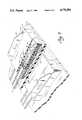
- FIG. 1is an isometric projection of a low-profile connector in accordance with the present invention positioned above an array of pin contacts extending upwardly from a printed circuit board;
- FIG. 2is a side view of two adjacent printed circuit boards with the lower-most board having a series of connectors of the type shown in FIG. 1 and in which the connectors also function as cable guides;
- FIG. 3is an isometric view of a frame structure for the connector of FIGS. 1 and 2.
- FIG. 3is an exploded perspective of a portion of a terminal board and receptacle strip (dotted line illustration) used in the connector of FIG. 1;
- FIG. 4is an enlarged isometric view of the connector of FIG. 1, in partial section, and in engagement with the pins of the printed circuit board.
- FIG. 1A connector in accordance with the present invention is shown in FIG. 1 and designated generally therein by the reference character 10.
- the connector 10terminates the end of a ribbon cable 12 of the type having a plurality of adjacent conductors aligned in a common plane.
- the connector 10includes a body 14 having first and second tabs 16 and 18 extending upwardly at the opposite ends of the body 14.
- the body 14is preferably formed as a parallelipiped from a moldable plastic and contains various sub-components described more fully below in relationship to FIGS. 3, 3A, and 4.
- the connector 10is designed to engage a multi-row array of upstanding connector pins P mounted on a printed circuit board 20 by positioning the connector 10 above the connector pins P and pressing the connector 10 into engagement with the pins P until the bottom face of the connector 10 engages the corresponding surface of the printed circuit board 20.
- the tabs 16 and 18are each provided with a respective through opening 22 which can be engaged by a connector removal tool (not shown).
- the through openings 22are each defined as an elongated slot aligned in the longitudinal direction of the ribbon cable 12 with a semi-circular cut-out on the upper side thereof.
- the tabs 16 and 18are spaced apart from one another by a dimension D (FIG. 1) that is larger than the lateral width dimension of the ribbon cable 12.
- the tabs 16 and 18can be used as a cable guide.
- a series of connectors 10are linearly aligned in a spaced apart relationship between two printed circuit boards 20 and 20'.
- the ribbon cable 12 from the first connector 10 in the series, on the right in FIG. 2is laid to the left through the upstanding tabs 16 and 18 of its immediately adjacent connector 10 with each successive connector 10 accommodating and guiding the ribbon cable 12 of the first connector 10.
- the tabs 16 and 18 of a particular connector 10function as a cable guide for the preceding connectors 10 in the series.
- the connector 10functions to provide an electrical connection with the printed circuit board 20 as well functioning as a cable guide for the ribbon cables 12 of other connectors 10.
- the body 14contains a frame 24, a terminal board 26, and a receptacle strip 28.
- the frame 24is formed from a pressed or stamped metal sheet (e.g., aluminum or steel) and, as shown in FIG. 3, includes a base 30 and the above-described tabs 16 and 18 at its opposite ends.
- a slot-like opening 32is formed in the base 30 to define a forward sub-base 30A and a rearward sub-base 30B.
- the slot-like opening 32has a lateral width dimension somewhat less than the dimension between the tabs 16 and 18.
- the receptacle strip 28includes a plurality of through bores (unnumbered) containing respective dual-beam receptacles R.
- Each receptacle Rincludes a pin 40 that extends into its associated through bore and is soldered in place to its connection pad 38.
- the principal axes of the receptacles Rare perpendicular to the plane of the terminal strip 26 and the connected conductive leads 42 of the ribbon cable 12.
- FIG. 3 and FIG. 3Aare assembled as shown in FIG. 4, that is, the receptacle strip 28 and its receptacles R are mounted to the terminal strip 26 with the proximate ends of the receptacles R soldered to their respective conductive pads 38.
- the end of the ribbon cable 12is prepared by stripping appropriate lengths of the outer jacketing and insulating sheaths (unnumbered) to expose the conductive leads 42 which are then soldered to their respective pads 36.
- the terminal board 26 and the attached receptacle strip 28constitutes a sub-assembly which is positioned between the tabs 16 and 18 of the frame 24 with the receptacle strip 28 in general registration with the slot-like opening 32.
- the body 14is molded in the general form of a low-profile parallelipiped with the tabs 16 and 18 extending upwardly as shown in FIGS. 1 and 4. As best shown in FIG. 4, the body 14 is formed to capture a portion of the insulating jacket of the ribbon cable 12 and the receptacle strip 28 is positioned to extend through the slot-like opening 32 between the forward and rearward sub-bases 30A and 30B to allow direct face-to-face contact with the printed circuit board 20. Molding can be accomplished using a multi-part mold with suitable plastics including polyphenylene sulfide.
- the connector 10 of the present inventionprovides a low-profile connector that permits convenient connection to a printed circuit board without the need for a socket or similar component to be mounted to the board and in which the distance that the connector 10 extends above the board is relatively small.
- the dimension between the top of the tabs 16 and 18 and the underside of the completed connector 10is less than 0.75 inches with 0.62 inches being typical, and the dimension between the top and underside of the molded body is less than 0.25 inches with 0.22 inches being typical. Accordingly, the present invention allows for a relatively small inter-board spacing in those design applications, as represented in FIG. 2, where a plurality of printed circuit boards are mounted in a close, adjacent relationship.
- the tabs 16 and 18allow a designer to use a series of connectors in a linearly spaced relationship with the tabs of the succeeding connectors in the series functioning as a cable guide or constraint for the cables of the preceding connectors in the series.
- the connector 10has been described as terminating a flat, ribbon type cable and using pin-receiving receptacles R in the receptacle strip 28 for engaging cylindrical pins P mounted on the printed circuit board.
- other types of cables having a defined lateral or cross-sectional dimensioncan be terminated by the connector and other types of contacts, including triple-beam receptacles, square pins, and contacts of the blade and bifurcated fork type, are likewise suitable.
Landscapes
- Coupling Device And Connection With Printed Circuit (AREA)
Abstract
Description
Claims (18)
Priority Applications (1)
| Application Number | Priority Date | Filing Date | Title |
|---|---|---|---|
| US07/071,800US4776806A (en) | 1987-07-10 | 1987-07-10 | Low-profile connector assembly |
Applications Claiming Priority (1)
| Application Number | Priority Date | Filing Date | Title |
|---|---|---|---|
| US07/071,800US4776806A (en) | 1987-07-10 | 1987-07-10 | Low-profile connector assembly |
Publications (1)
| Publication Number | Publication Date |
|---|---|
| US4776806Atrue US4776806A (en) | 1988-10-11 |
Family
ID=22103673
Family Applications (1)
| Application Number | Title | Priority Date | Filing Date |
|---|---|---|---|
| US07/071,800Expired - Fee RelatedUS4776806A (en) | 1987-07-10 | 1987-07-10 | Low-profile connector assembly |
Country Status (1)
| Country | Link |
|---|---|
| US (1) | US4776806A (en) |
Cited By (9)
| Publication number | Priority date | Publication date | Assignee | Title |
|---|---|---|---|---|
| US4871319A (en)* | 1988-12-21 | 1989-10-03 | Amp Incorporated | Molded circuit board for ribbon cable connector |
| US4948379A (en)* | 1989-03-17 | 1990-08-14 | E. I. Du Pont De Nemours And Company | Separable, surface-mating electrical connector and assembly |
| US5282752A (en)* | 1992-08-07 | 1994-02-01 | E. I. Du Pont De Nemours And Company | Combination connector tool |
| US5351391A (en)* | 1992-08-07 | 1994-10-04 | E. I. Dupont De Nemours & Company | Tool for assembling modular header connectors and modular receptacle connectors |
| US6061246A (en)* | 1997-09-13 | 2000-05-09 | Samsung Electronics Co., Ltd. | Microelectric packages including flexible layers and flexible extensions, and liquid crystal display modules using the same |
| US20030162435A1 (en)* | 2002-02-12 | 2003-08-28 | Glen Holman | Cable connector hood and clamp |
| US20040157482A1 (en)* | 2003-02-06 | 2004-08-12 | Ohtsuki Tomonari | Connector |
| US7223119B2 (en) | 2002-10-23 | 2007-05-29 | Fci | Cable connector assembly and system |
| US9690056B2 (en) | 2014-06-25 | 2017-06-27 | Samtec, Inc. | Connector assembly |
Citations (15)
| Publication number | Priority date | Publication date | Assignee | Title |
|---|---|---|---|---|
| US3689865A (en)* | 1968-03-11 | 1972-09-05 | Texas Instruments Inc | Connector |
| US3701964A (en)* | 1970-09-04 | 1972-10-31 | Lockheed Aircraft Corp | Flat cable electrical wiring system |
| US3851294A (en)* | 1972-10-31 | 1974-11-26 | Fiat Spa | Connector for sealingly interconnecting a multiple core electric cable and a printed circuit |
| US3915535A (en)* | 1974-02-21 | 1975-10-28 | Amp Inc | Coaxial cable receptacle for printed circuit boards |
| US3963319A (en)* | 1974-12-12 | 1976-06-15 | Amp Incorporated | Coaxial ribbon cable terminator |
| US4005921A (en)* | 1976-02-23 | 1977-02-01 | E. I. Du Pont De Nemours And Company | Transmission cable connector and termination method |
| US4157612A (en)* | 1977-12-27 | 1979-06-12 | Bell Telephone Laboratories, Incorporated | Method for improving the transmission properties of a connectorized flat cable interconnection assembly |
| US4358172A (en)* | 1980-04-23 | 1982-11-09 | Thomas & Betts Corporation | Connector for electrical interconnection of circuit board and flat multiconductor cable |
| US4406512A (en)* | 1981-07-24 | 1983-09-27 | E. I. Du Pont De Nemours And Company | Triple row coax cable connector |
| US4489999A (en)* | 1983-02-15 | 1984-12-25 | Motorola, Inc. | Socket and flexible PC board assembly and method for making |
| US4602831A (en)* | 1983-09-26 | 1986-07-29 | Amp Incorporated | Electrical connector and method of making same |
| US4605276A (en)* | 1983-03-30 | 1986-08-12 | E. I. Du Pont De Nemours And Company | Two row coaxial cable connector |
| US4639063A (en)* | 1985-12-20 | 1987-01-27 | Amp Incorporated | Electrical connector for flexible film circuits |
| US4647133A (en)* | 1985-04-18 | 1987-03-03 | Innovus | Electrical interconnect system |
| US4682828A (en)* | 1985-12-06 | 1987-07-28 | 501 Woven Electronics Corporation | Bus bar bridged pc board for transitional termination of multiple cables and method |
- 1987
- 1987-07-10USUS07/071,800patent/US4776806A/ennot_activeExpired - Fee Related
Patent Citations (15)
| Publication number | Priority date | Publication date | Assignee | Title |
|---|---|---|---|---|
| US3689865A (en)* | 1968-03-11 | 1972-09-05 | Texas Instruments Inc | Connector |
| US3701964A (en)* | 1970-09-04 | 1972-10-31 | Lockheed Aircraft Corp | Flat cable electrical wiring system |
| US3851294A (en)* | 1972-10-31 | 1974-11-26 | Fiat Spa | Connector for sealingly interconnecting a multiple core electric cable and a printed circuit |
| US3915535A (en)* | 1974-02-21 | 1975-10-28 | Amp Inc | Coaxial cable receptacle for printed circuit boards |
| US3963319A (en)* | 1974-12-12 | 1976-06-15 | Amp Incorporated | Coaxial ribbon cable terminator |
| US4005921A (en)* | 1976-02-23 | 1977-02-01 | E. I. Du Pont De Nemours And Company | Transmission cable connector and termination method |
| US4157612A (en)* | 1977-12-27 | 1979-06-12 | Bell Telephone Laboratories, Incorporated | Method for improving the transmission properties of a connectorized flat cable interconnection assembly |
| US4358172A (en)* | 1980-04-23 | 1982-11-09 | Thomas & Betts Corporation | Connector for electrical interconnection of circuit board and flat multiconductor cable |
| US4406512A (en)* | 1981-07-24 | 1983-09-27 | E. I. Du Pont De Nemours And Company | Triple row coax cable connector |
| US4489999A (en)* | 1983-02-15 | 1984-12-25 | Motorola, Inc. | Socket and flexible PC board assembly and method for making |
| US4605276A (en)* | 1983-03-30 | 1986-08-12 | E. I. Du Pont De Nemours And Company | Two row coaxial cable connector |
| US4602831A (en)* | 1983-09-26 | 1986-07-29 | Amp Incorporated | Electrical connector and method of making same |
| US4647133A (en)* | 1985-04-18 | 1987-03-03 | Innovus | Electrical interconnect system |
| US4682828A (en)* | 1985-12-06 | 1987-07-28 | 501 Woven Electronics Corporation | Bus bar bridged pc board for transitional termination of multiple cables and method |
| US4639063A (en)* | 1985-12-20 | 1987-01-27 | Amp Incorporated | Electrical connector for flexible film circuits |
Cited By (11)
| Publication number | Priority date | Publication date | Assignee | Title |
|---|---|---|---|---|
| US4871319A (en)* | 1988-12-21 | 1989-10-03 | Amp Incorporated | Molded circuit board for ribbon cable connector |
| US4948379A (en)* | 1989-03-17 | 1990-08-14 | E. I. Du Pont De Nemours And Company | Separable, surface-mating electrical connector and assembly |
| EP0398473A1 (en)* | 1989-03-17 | 1990-11-22 | E.I. Du Pont De Nemours And Company | Separable, surface-mating electrical connector and assembly |
| US5282752A (en)* | 1992-08-07 | 1994-02-01 | E. I. Du Pont De Nemours And Company | Combination connector tool |
| US5351391A (en)* | 1992-08-07 | 1994-10-04 | E. I. Dupont De Nemours & Company | Tool for assembling modular header connectors and modular receptacle connectors |
| US6061246A (en)* | 1997-09-13 | 2000-05-09 | Samsung Electronics Co., Ltd. | Microelectric packages including flexible layers and flexible extensions, and liquid crystal display modules using the same |
| US20030162435A1 (en)* | 2002-02-12 | 2003-08-28 | Glen Holman | Cable connector hood and clamp |
| US7223119B2 (en) | 2002-10-23 | 2007-05-29 | Fci | Cable connector assembly and system |
| US20040157482A1 (en)* | 2003-02-06 | 2004-08-12 | Ohtsuki Tomonari | Connector |
| US6960094B2 (en)* | 2003-02-06 | 2005-11-01 | Ddk Ltd. | Flat and thin connector for electrically connecting a flexible printed circuit board and a hard board |
| US9690056B2 (en) | 2014-06-25 | 2017-06-27 | Samtec, Inc. | Connector assembly |
Similar Documents
| Publication | Publication Date | Title |
|---|---|---|
| US4225209A (en) | Electrical connector receptacle | |
| US4365856A (en) | Electric connector for coaxial ribbon cable | |
| US6231355B1 (en) | Matched impedance connector having retention device on a grounding plane | |
| US6585528B1 (en) | Wire spacer for high speed cable termination | |
| US5139426A (en) | Adjunct power connector | |
| US4686607A (en) | Daughter board/backplane assembly | |
| US5203716A (en) | Terminal block for printed circuit boards | |
| KR950012466B1 (en) | Pressurized Contact Electrical Connectors for Flat Flexible Cables | |
| JP3013756B2 (en) | Board connector | |
| US4909754A (en) | Connectors for telecommunications lines | |
| US5125846A (en) | Input-output electrical connector | |
| US5618202A (en) | Connector having strip line structure | |
| US6270358B1 (en) | Low-voltage male connector | |
| EP0189234A1 (en) | Connector with conductor retention means | |
| KR101168093B1 (en) | Connector and cable retainer | |
| US5667401A (en) | Cable connector, circuit board and system having circuit boards connected together by the cable connector | |
| JPH0332187B2 (en) | ||
| US7241173B2 (en) | Electrical connector insert and apparatus and associated fabrication method | |
| US4776806A (en) | Low-profile connector assembly | |
| US5299942A (en) | Input-output electrical connector | |
| EP0643449A1 (en) | Cable connector for a ribbon cable | |
| US4653828A (en) | Pin shroud with universal latch means | |
| US5261828A (en) | Misalignment tolerant edge connector assembly | |
| US6468106B2 (en) | Fret assembly | |
| KR100378932B1 (en) | Electrical connector and method of assembling same |
Legal Events
| Date | Code | Title | Description |
|---|---|---|---|
| AS | Assignment | Owner name:E. I. DU PONT DE NEMOURS AND COMPANY, WILMINGTON, Free format text:ASSIGNMENT OF ASSIGNORS INTEREST.;ASSIGNOR:ADAMS, JOHN E.;REEL/FRAME:004748/0129 Effective date:19870629 Owner name:E. I. DU PONT DE NEMOURS AND COMPANY, DELAWARE Free format text:ASSIGNMENT OF ASSIGNORS INTEREST;ASSIGNOR:ADAMS, JOHN E.;REEL/FRAME:004748/0129 Effective date:19870629 | |
| FPAY | Fee payment | Year of fee payment:4 | |
| AS | Assignment | Owner name:CHEMICAL BANK, NEW YORK Free format text:SECURITY INTEREST;ASSIGNOR:BERG TECHNOLOGY, INC.;REEL/FRAME:006497/0231 Effective date:19930226 | |
| FPAY | Fee payment | Year of fee payment:8 | |
| AS | Assignment | Owner name:BERG TECHNOLOGY, INC., NEVADA Free format text:ASSIGNMENT OF ASSIGNORS INTEREST;ASSIGNOR:E.I. DU PONT DE NEMOURS AND COMPANY;REEL/FRAME:008321/0185 Effective date:19961209 | |
| REMI | Maintenance fee reminder mailed | ||
| LAPS | Lapse for failure to pay maintenance fees | ||
| FP | Lapsed due to failure to pay maintenance fee | Effective date:20001011 | |
| STCH | Information on status: patent discontinuation | Free format text:PATENT EXPIRED DUE TO NONPAYMENT OF MAINTENANCE FEES UNDER 37 CFR 1.362 |