US4776749A - Robotic device - Google Patents
Robotic deviceDownload PDFInfo
- Publication number
- US4776749A US4776749AUS06/843,887US84388786AUS4776749AUS 4776749 AUS4776749 AUS 4776749AUS 84388786 AUS84388786 AUS 84388786AUS 4776749 AUS4776749 AUS 4776749A
- Authority
- US
- United States
- Prior art keywords
- members
- support structure
- positioning
- respect
- axial movement
- Prior art date
- Legal status (The legal status is an assumption and is not a legal conclusion. Google has not performed a legal analysis and makes no representation as to the accuracy of the status listed.)
- Expired - Fee Related
Links
- 230000008878couplingEffects0.000claimsdescription28
- 238000010168coupling processMethods0.000claimsdescription28
- 238000005859coupling reactionMethods0.000claimsdescription28
- 230000007246mechanismEffects0.000description22
- 230000003134recirculating effectEffects0.000description11
- 238000004519manufacturing processMethods0.000description10
- 238000005452bendingMethods0.000description8
- 238000003754machiningMethods0.000description5
- 230000006835compressionEffects0.000description4
- 238000007906compressionMethods0.000description4
- 238000000034methodMethods0.000description3
- 241000282412HomoSpecies0.000description2
- 230000015556catabolic processEffects0.000description2
- 238000006731degradation reactionMethods0.000description2
- 238000005304joiningMethods0.000description2
- 238000003801millingMethods0.000description2
- 230000008569processEffects0.000description2
- 239000013598vectorSubstances0.000description2
- 238000003466weldingMethods0.000description2
- 241001465754MetazoaSpecies0.000description1
- RTAQQCXQSZGOHL-UHFFFAOYSA-NTitaniumChemical compound[Ti]RTAQQCXQSZGOHL-UHFFFAOYSA-N0.000description1
- 230000004913activationEffects0.000description1
- 239000012190activatorSubstances0.000description1
- 230000003190augmentative effectEffects0.000description1
- 150000001875compoundsChemical class0.000description1
- 230000001010compromised effectEffects0.000description1
- 230000001186cumulative effectEffects0.000description1
- 230000001419dependent effectEffects0.000description1
- 238000005553drillingMethods0.000description1
- 230000002996emotional effectEffects0.000description1
- 238000005516engineering processMethods0.000description1
- 238000011067equilibrationMethods0.000description1
- 230000003993interactionEffects0.000description1
- 238000012423maintenanceMethods0.000description1
- 239000000463materialSubstances0.000description1
- 230000003278mimic effectEffects0.000description1
- 230000003287optical effectEffects0.000description1
- 238000004904shorteningMethods0.000description1
- 239000007787solidSubstances0.000description1
- 230000006641stabilisationEffects0.000description1
- 238000011105stabilizationMethods0.000description1
- 230000003068static effectEffects0.000description1
- 230000002277temperature effectEffects0.000description1
- 229910052719titaniumInorganic materials0.000description1
- 239000010936titaniumSubstances0.000description1
Images


Classifications
- B—PERFORMING OPERATIONS; TRANSPORTING
- B23—MACHINE TOOLS; METAL-WORKING NOT OTHERWISE PROVIDED FOR
- B23Q—DETAILS, COMPONENTS, OR ACCESSORIES FOR MACHINE TOOLS, e.g. ARRANGEMENTS FOR COPYING OR CONTROLLING; MACHINE TOOLS IN GENERAL CHARACTERISED BY THE CONSTRUCTION OF PARTICULAR DETAILS OR COMPONENTS; COMBINATIONS OR ASSOCIATIONS OF METAL-WORKING MACHINES, NOT DIRECTED TO A PARTICULAR RESULT
- B23Q1/00—Members which are comprised in the general build-up of a form of machine, particularly relatively large fixed members
- B23Q1/25—Movable or adjustable work or tool supports
- B23Q1/44—Movable or adjustable work or tool supports using particular mechanisms
- B23Q1/50—Movable or adjustable work or tool supports using particular mechanisms with rotating pairs only, the rotating pairs being the first two elements of the mechanism
- B23Q1/54—Movable or adjustable work or tool supports using particular mechanisms with rotating pairs only, the rotating pairs being the first two elements of the mechanism two rotating pairs only
- B23Q1/545—Movable or adjustable work or tool supports using particular mechanisms with rotating pairs only, the rotating pairs being the first two elements of the mechanism two rotating pairs only comprising spherical surfaces
- B23Q1/5462—Movable or adjustable work or tool supports using particular mechanisms with rotating pairs only, the rotating pairs being the first two elements of the mechanism two rotating pairs only comprising spherical surfaces with one supplementary sliding pair
- B—PERFORMING OPERATIONS; TRANSPORTING
- B25—HAND TOOLS; PORTABLE POWER-DRIVEN TOOLS; MANIPULATORS
- B25J—MANIPULATORS; CHAMBERS PROVIDED WITH MANIPULATION DEVICES
- B25J17/00—Joints
- B25J17/02—Wrist joints
- B25J17/0258—Two-dimensional joints
- B25J17/0266—Two-dimensional joints comprising more than two actuating or connecting rods
- B—PERFORMING OPERATIONS; TRANSPORTING
- B25—HAND TOOLS; PORTABLE POWER-DRIVEN TOOLS; MANIPULATORS
- B25J—MANIPULATORS; CHAMBERS PROVIDED WITH MANIPULATION DEVICES
- B25J17/00—Joints
- B25J17/02—Wrist joints
- B25J17/0258—Two-dimensional joints
- B25J17/0275—Universal joints, e.g. Hooke, Cardan, ball joints
- B—PERFORMING OPERATIONS; TRANSPORTING
- B25—HAND TOOLS; PORTABLE POWER-DRIVEN TOOLS; MANIPULATORS
- B25J—MANIPULATORS; CHAMBERS PROVIDED WITH MANIPULATION DEVICES
- B25J5/00—Manipulators mounted on wheels or on carriages
- B25J5/02—Manipulators mounted on wheels or on carriages travelling along a guideway
- B—PERFORMING OPERATIONS; TRANSPORTING
- B25—HAND TOOLS; PORTABLE POWER-DRIVEN TOOLS; MANIPULATORS
- B25J—MANIPULATORS; CHAMBERS PROVIDED WITH MANIPULATION DEVICES
- B25J9/00—Programme-controlled manipulators
- B25J9/003—Programme-controlled manipulators having parallel kinematics
- B25J9/0063—Programme-controlled manipulators having parallel kinematics with kinematics chains having an universal joint at the base
- B25J9/0069—Programme-controlled manipulators having parallel kinematics with kinematics chains having an universal joint at the base with kinematics chains of the type universal-prismatic-universal
- Y—GENERAL TAGGING OF NEW TECHNOLOGICAL DEVELOPMENTS; GENERAL TAGGING OF CROSS-SECTIONAL TECHNOLOGIES SPANNING OVER SEVERAL SECTIONS OF THE IPC; TECHNICAL SUBJECTS COVERED BY FORMER USPC CROSS-REFERENCE ART COLLECTIONS [XRACs] AND DIGESTS
- Y10—TECHNICAL SUBJECTS COVERED BY FORMER USPC
- Y10T—TECHNICAL SUBJECTS COVERED BY FORMER US CLASSIFICATION
- Y10T29/00—Metal working
- Y10T29/51—Plural diverse manufacturing apparatus including means for metal shaping or assembling
- Y10T29/5152—Plural diverse manufacturing apparatus including means for metal shaping or assembling with turret mechanism
- Y10T29/5154—Plural diverse manufacturing apparatus including means for metal shaping or assembling with turret mechanism tool turret
- Y—GENERAL TAGGING OF NEW TECHNOLOGICAL DEVELOPMENTS; GENERAL TAGGING OF CROSS-SECTIONAL TECHNOLOGIES SPANNING OVER SEVERAL SECTIONS OF THE IPC; TECHNICAL SUBJECTS COVERED BY FORMER USPC CROSS-REFERENCE ART COLLECTIONS [XRACs] AND DIGESTS
- Y10—TECHNICAL SUBJECTS COVERED BY FORMER USPC
- Y10T—TECHNICAL SUBJECTS COVERED BY FORMER US CLASSIFICATION
- Y10T408/00—Cutting by use of rotating axially moving tool
- Y10T408/36—Machine including plural tools
- Y10T408/37—Turret of tools
- Y—GENERAL TAGGING OF NEW TECHNOLOGICAL DEVELOPMENTS; GENERAL TAGGING OF CROSS-SECTIONAL TECHNOLOGIES SPANNING OVER SEVERAL SECTIONS OF THE IPC; TECHNICAL SUBJECTS COVERED BY FORMER USPC CROSS-REFERENCE ART COLLECTIONS [XRACs] AND DIGESTS
- Y10—TECHNICAL SUBJECTS COVERED BY FORMER USPC
- Y10T—TECHNICAL SUBJECTS COVERED BY FORMER US CLASSIFICATION
- Y10T408/00—Cutting by use of rotating axially moving tool
- Y10T408/91—Machine frame
- Y10T408/93—Machine frame including pivotally mounted tool-carrier
- Y10T408/935—Machine frame including pivotally mounted tool-carrier including laterally movable tool-carrier
Definitions
- This inventionis directed to a robotic device capable of positioning a working implement in a precise and reproducible spatial location with respect to a reference of origin and dynamically repositioning said working implement at a further spatial location which is precisely and reproducibly located with respect to said reference of origin.
- Machine tools and other devicesexist for the manufacture of components having precise tolerances and precise shapes. Until very recently, these machine tools all required a human operator for their function. Other manufacturing techniques and technology such as welding, riveting or assembly also until very recently were impossible without a human to perform these functions.
- robotic devicesFor certain operations which in the past required a human technician, such as welding or assembly, a class of robotic devices have been developed. For the most part these robotic devices mimic the function of a human arm. They consist of a series of segments which are connected together about axes of rotation to form an articulated arm. Generally, the axes of rotation would be orthogonal in order to give the articulated arm the ability to move within three dimensional space.
- the arm segmentsextend from the base and have a working implement on the end of the arm distal from the base. The arm thus forms a cantilever between the base and the working implement.
- articulated armsrepresent great steps forward with respect to automating certain tasks, they are not without their problems and/or limitations. Because the arm is a cantilever supported at only one end on the base, the loads which the implement can carry or the force which the implement can apply are limited. Additionally, as the implement moves toward or away from the base the lever arm between the implement and the base is variable. This, along with several different axes of rotation within the articulated arm contributes to the difficulty of computer numerical control, "CNC", of these devices.
- CNCcomputer numerical control
- the variability of the lever arm of a cantilevered articulated armalso contributes to a loss of accuracy with respect to these devices.
- the accuracy of these devicesis best when the lever arm is short. As the lever arm is elongated, the accuracy degrades. In addition, each time a point of rotation must be traversed in moving from one segment of the cantilevered arm to the next, a degradation of the accuracy of the device also occurs. Because the arm is cantilevered, there is a bending moment in each of the individual points of rotation. Since the degradation of the accuracy is cumulative, by the time one reaches the implement end of the arm the accuracy of the arm is severely compromised.
- a robotic devicehaving a support structure and an implement element. At least two positioning members are attached to the implement element at a first position. At least two positioning members are attached to the implement at a second position. A further positioning member also attaches to the implement element. A first connecting means is utilized to connect the first positioning members to the support structure and a second connecting means is utilized to attach the second positioning members to the support structure. A further connecting means is utilized to attach the further positioning element to the support structure.
- the devicefurther includes actuator means for independently moving at least either the first two positioning members or the second two positioning members axially along axes between the support structure and the implement element whereby the position of the implement element with respect to the support structure is controlled by the movement of the positioning members.
- first positioning membersare attached to the implement element about a first common center of rotation as is the further member.
- the second positioning membersare attached to the implement element about a second common center of rotation.
- each of the positioning membersare attached to the support structure utilizing a gimbal means, and each of the positioning members are movable by the actuator means independently axially along axes between the implement element and the support structure to achieve both positioning of the implement element and maintaining its normality to a workpiece.
- a first triangular supportis formed of first and second members and a portion of the support structure. Each of these first and second members are connected by connecting means to the support structure.
- a second triangular supportis formed of third and fourth members and a further portion of the support structure. Each of the third and fourth members are connected by a connecting means to the support structure.
- the apex of the first triangular support where the first and second members joinis attached to the tool carrier by a first coupling means and in a similar manner, the apex of the second triangular structure where the third and fourth members join is attached to the tool carrier by a second coupling means.
- An axial moving meansis provided for independently axially moving the first and second members with respect to the support structure and the third and fourth members with respect to the support structure.
- a further meansis operatively associated with both the support structure and the tool carrier further moving the tool carrier independently of the movement imparted to the tool carrier by the axial moving means.
- the further meansincludes a fifth member attaching to the tool carrier in association with the first coupling means and the connecting means for connecting the individual members to the support structure would each include a pivoting means and an axial movement means.
- the pivoting meansprovides for pivotal movement of the individual members with respect to the support structure and the axial movement means provides for axial movement of the individual members with respect to the support structure.
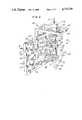
- FIG. 1is an isometric view of a first embodiment of the invention
- FIG. 2is a side elevation view in section of an alternate embodiment of the invention
- FIG. 3is a plan view in partial section about the line 3--3 of FIG. 1;
- FIG. 4is a fragmentary isometric view in partial section of a component found on the right hand side of FIG. 3;
- FIG. 5is an isometric view of a component of the invention seen repeatedly used in FIG. 1 in five various locations within FIG. 1;
- FIG. 6is an isometric view of a further alternate embodiment of the invention showing certain components of the invention in solid line in a first spatial configuration and in phantom lines in further spatial configurations.
- This inventionis directed to a robotic device used for positioning of a working implement in precise locations and positions in three dimensional space. Because of certain principles inherent in the invention it can be utilized for many diverse machining and manufacturing processes ranging in scope from certain micro processes such as those utilized during integrated circuit manufacture to macro processes such as ship and aircraft building.
- a working implementcan be positioned in space with great accuracy which is independent of the spatial orientation of the implement with respect to a support structure.
- simple tensile and compressive forcesare utilized to position the working implement.
- the robotic device of the inventionis capable of both manual control and computer numeric control (CNC), with CNC control preferred for total automation of the device.
- the robotic device of the inventionis capable of achieving positional accuracies of the working implement many fold greater than present articulated arm robotic devices. Independent of the scale of the robotic device of the invention, i.e., whether it is being utilized in a micro or macro environment, high degrees of accuracy can be achieved. This accuracy is maintained throughout the "geometrical" range of the device irrespective of the positioning of the working implement with respect to a working surface.
- reach of the armis only approximately 100 inches, with reproducibility of plus or minus 0.010 inches, and absolute reproducibility of plus or minus 0.05 inches.
- a robotic device of the invention of the same scalewould have a reach of over 1200 inches and an accuracy within that reach of plus or minus about 0.0002 inches and if a constant environment was utilized so as to mitigate temperature effects, this accuracy could be increased to plus or minus about 0.00002 inches.
- the robotic device of the inventionis capable of being positioned within three dimensional space above, below or to any side of a working surface and still maintain the accuracy of the device. Further, the robotic device of the invention can be utilized in a dynamic mode maintaining this accuracy as the robotic device of the invention moves a working implement through three dimensional space as might be necessary during fabrication and assembly of a complex structure. The robotic device of the invention is capable of being utilized on both horizontal and vertical planes while maintaining tool normality of a working implement with respect to a working surface of a component.
- the robotic device of the inventionessentially serves as a positioning structure and is not dedicated to a single or related family of working implements, the robotic device of the invention is capable of a variety of machining, assembly and other operations depending upon the implement utilized. Because of the structure of the robotic device of the invention, machine tool accuracy can be achieved throughout the range of the device and all normal machine tool functions can be performed. Since the device is in fact not limited in size or space, it can be scaled up and equipped with appropriate working implements capable of performing complex assembly on large structures such as airplanes and ships.
- FIG. 6a portion of a robotic structural device 10 is shown.
- the device 10is shown utilizing a mobile gantry type structure generally depicted by the numeral 12.
- the mobile gantry 12would include an overhead horizontal beam 14 and an appropriate vertical sidewall structure 16 as shown.
- a sidewall similar to sidewall 16would support the other end of the beam 14.
- the other wallis not shown, its function and structure being identical to that of the wall 16.
- the wall 16(and its mate on the other side of the beam 14) can be mounted on appropriate wheels such as wheels collectively identified by the numeral 18.
- the wheels 18could ride on tracks such as tracks 20 shown in FIG. 6.
- the device 10would be useful for machining and manufacturing operations on large structures.
- the device 10 in FIG. 6is shown working in several views in solid and phantom line on a working structure 22.
- a representational tool turret 24is shown attached to the device 10.
- the tool turret 24would of course include a variety of working tools located on it. Since tool turrets such as the turret 24 and working tools located thereon are known, a detailed description of these components is not deemed necessary for the understanding of this invention, it being sufficient to say that they would be appropriately mounted on the device 10 with the device 10 serving its most important and primary function of correctly positioning the working tools against the working structure 22 throughout three dimensional space with respect to the working structure 22.
- a central tool post or implement element 26is attached to the gantry 12 utilizing five positioning members.
- the individual positioning membersare joined to the gantry 12 utilizing a like number of connecting members or connecting means collectively identified by the numeral 28.
- the positioning memberscan be thought of as occurring in three sets. These include the first set or upper set having positioning member 30 and positioning member 32 as members of this set. Below the first set is a second set composed of members 34 and 36. The final positioning member or further positioning member is positioning member 38. Positioning member 38 extends from the beam 14, whereas the other positioning members extend from the sidewall 16.
- Each of the positioning members 30, 32, 34, 36 and 38are movably joined to the gantry 12 by their respective connecting member 28.
- the positioning members 30, 32 and 38are joined to the tool post implement 26 in the embodiment of FIG. 6 at a common center of rotation or coupling point 40 located on one end of the tool post implement 26.
- the other two positioning members, the positioning members 34 and 36 of the second set,are joined to the tool post implement at a second or further coupling point 42 formed on the other end of the tool post implement 26.
- the attachment of the members 30, 32, 34, 36 and 38 to the tool post implement 26was noted as being at coupling means, i.e. the coupling points 40 and 42 and the attachment of these members to the gantry 12 at connecting means, i.e. the connecting members 28.
- the different words “connecting” and “coupling”are used simply to differentiate whether the members 30, 32, 34, 36 and 38 are attaching to the structural support, i.e. the gantry 12, or to the tool post implement 26.
- the use of two different words “connecting” and “coupling” to describe the "movable” attachmentsis for descriptive reasons only to achieve clarity and easy of understanding of this specification as should not be thought of as being limiting.
- each of the positioning members 30, 32, 34, 36 and 38is located between the gantry 12 and the tool post implement 26 and a further portion of each of the respective members are located external of the gantry 12 that is they extend to the left or above the respective connecting members 28.
- the ratio of these "external portions" of the respective positioning membersvaries depending on the position of the tool post implement 26.
- Each of the positioning members 30, 32, 34, 36 and 38are pivotable with respect to the support structure, i.e., either the sidewall 16 or the beam 14 from which they extend. In addition, they also are axially movable with respect to those same support structures, the beam 14 and the sidewall 16, along the length or elongated axis of the positioning members 30, 32, 34, 36 and 38. Because of this, the tool post implement 26 is freely positional in three dimensional space within the gantry 12, and at the same time the tool post implement 26 can be held normal to, that is perpendicular to, whatever surface it might be working on irrespective of whether this surface is simple, complex, planar, arcuate or convoluted.
- the two positioning members 30 and 32 of the first or upper set in conjunction with the portion of the sidewall 16are triangulated to form a rigid structure.
- the sameis true with respect to the positioning members 34 and 36 of the second or lower set in conjunction with a further portion of sidewall 16.
- the upper set of positioning members, members 30 and 32 and the further positioning member, positioning member 38, in conjunction with a portion of the gantry 14 extending through sidewall 16 and beam 14are also triangulated.
- the triangulation of the respective positioning membersfixes the position of the tool post implement 26 with respect to the gantry 12 by the tension and compression vectors extending along the elongated axis of the respective positioning members.
- the positioning members 30, 32, 34, 36 and 38connect to and extend between the coupling points 40 and 42 on the tool post implement 26 and the connecting members 28 on the the gantry 12 utilizing only those tension and compression vectors which extend along the elongated axis of the positioning members 30, 32, 34, 36 and 38.
- the tool post implement 26is in fact supported only by tension and compressional forces along the elongated dimension of the positioning members, great force can be exerted on the tool post implement 26 and a working tool attached thereto as might be necessary for certain manufacturing functions, as, for instance, drilling in titanium or other extremely hard materials. These same forces simply are not available in articulated arm devices because of the bending moments involved in those devices. At the same time, extremely delicate and precisely accurate movements in positioning of a working tool located on the tool post implement 26 can be achieved by elongating and foreshortening the portion of one or more of the positioning members 30, 32, 34, 36 and 38 located between the tool post implement 26 and the gantry 12.
- the positioning member 38can also pivot within its connecting member 28 with respect to the beam portion 14 of the gantry 12.
- each of the positioning members 30, 32, 34, 36 and 38are capable of extending or retracting along an axis axially passing along the elongated dimension of the positioning members 30, 32, 34, 36 and 38.
- this motioncan be considered as being axial, linear or translational movement along the elongated axis of the respective members.
- This individual axial, linear or translational motion of any particular member when combined with the other memberscan result in either linear or rotational movement of the tool post implement 26 depending upon the combined motion of all of the members.
- any one of the members 30, 32, 34, 36 or 38 with respect to at least one other of the respective memberscan be at the same velocity or at a different velocity resulting in either constant or differential movement between the respective members.
- the tool post implement 26is held in one spatial configuration against a first portion of the working structure 22 and in the two phantom line views, the tool post implement 28 is held in further positions with respect to the working structure 22.
- FIG. 6in moving from the solid line view of the tool post implement 26 to the phantom line view shown in the right foreground, it can be seen that not only is the tool post implement 26 moved from left to right across the surface of the working surface 22, but at the same time it has been inclined with respect to a hypothetical vertical axis from about 15 degrees to the left of a vertical axis to approximately 15 degrees to the right of the same vertical axis.
- this inclination and movement of the tool post implement 26 and a working tool attached theretocould be made in a dynamic manner while at all times holding the working implement against the working structure 22 to execute a machine or assembly function during movement.
- the tool post implement 26can be made to move parallel to the sidewall 16, can be made to move perpendicular to the sidewall 16, can be moved in a straight line which is at an angle to the sidewall 16, can be moved in an arcuate manner curving essentially horizontal to the sidewall 16, can be moved in an arcuate manner curving essentially vertical to the sidewall 16, can be raised or lowered with respect to the beam 14, or any combination of two or more of these movements. It is thus evident that any working tool located on the tool post implement 26 can be moved in simple or complex manners throughout the three dimensional space in the interior of the gantry 12.
- FIG. 1a further embodiment of the invention is described in detail.
- the device 44has a supporting structure generally defined by the numeral 46 composed of a cross braced wall 48 and a vertical braced extension 50.
- Five identical gimbals 52, 54, 56, 58 and 60are appropriately suspended in the support structure 46.
- the gimbalsserve as a portion of the connection means.
- four of these gimbals, gimbals 52, 54, 56 and 58are located in the wall 48 and the fifth gimbal, gimbal 60, in the vertical extension 50.
- a first positioning member 62is associated with the gimbal 50 and a second positioning member 64 is associated with the gimbal 54.
- a third positioning member 66is associated with gimbal 66 and a fourth positioning member 68 is associated with the gimbal 58.
- a further positioning member 70is associated with gimbal 60. The positioning members 62, 64, 66, 68 and 70 are utilized to support a tool post 72.
- Positioning members 60, 62, 64 and 70attach to an upper common coupler 74 while the positioning members 66 and 68 attach to a lower common coupler 76.
- An appropriate tool turret or carousel 78extends from the tool post 72.
- a plurality of tools collectively identified by the numeral 80are located on the carousel 78.
- the tools 80would be common machine tools as are standard in the art.
- Representationally depicted by cylinder 82would be a variable speed tool motor and tool feed and retract mechanism. Insofar as these are only one of many different working implements which could be utilized with the robotic device 44, for the brevity of this specification these components are only depicted schematically. The other components of the robotic device 44 discussed in detail are utilized to position these working implements within three dimensional space.
- the positioning members 62, 64 and 66are connected about a common center of rotation within the upper coupler 74.
- the coupler of this embodimentis seen in greater detail in FIG. 4.
- On the lower end of positioning member 70is a ball 84.
- the ball 84is fixed to the lower end of the positioning member 70 so as to become an integral part thereof.
- the interior of the ball 84is hollow with an opening into this hollow interior opening out of the lower pole of the ball 84.
- the tool post 72extends upwardly through the opening in the lower pole of the ball 84 and terminates in an inner ball 86 which is positioned co-spherically within the hollow interior of the ball 84. Since both the balls 84 and 86 have the same common center, this allows for procession of the positioning member 70 with respect to the tool post 72.
- Encircling the ball 84are upper and lower disks 88 and 90, respectively, which are connected via a joining block 92 to positioning member 62.
- the interior of the disks 88 and 90are spherical so as to fit around the ball 84 allowing the disks 88 and 90 and the joining member 62 attached thereto to also rotate about the common center of the balls 84 and 86.
- a third, narrower disk, disk 94is located between the two disks 88 and 90.
- the disk 94is attached to the positioning member 64.
- the interior surface of the disk 94is also spherical so as to fit around the outside surface of the ball 84 to connect the positioning member 64 to the remainder of the structure and allow it to rotate around the same common center of rotation as the positioning member 62 and the positioning member 70.
- the disks 88 and 90each include grooves collectively identified by the numeral 96 located therein which receive projections collectively identified by the numeral 98 which project perpendicularly up or down from the upper and lower planar surfaces of the disk 94.
- the grooves 96are sized to be slightly oversized with respect to the projections 98, allowing for rotation of the disk 94 between the disks 88 and 90. This results in stabilization of the total structure and maintenance of all of the components about about a common center of rotation while still allowing flexure of the positioning members 62 and 64 about the common center of rotation.
- the thickness of the sandwich formed by the disks 88, 94 and 90 combined with the size of the ball 84, the size of the opening in the lower pole of the ball 84 and the arcuate angle of the grooves 96can be conveniently made so as to allow for sufficient degrees of rotational freedom about the common center at which each of the four appendages, positioning members 62, 64 and 70 and tool post 72, attach to the upper coupler 74. Because the overall size of the robotic device 44 will be chosen with respect to the structure being worked on, i.e., from micro to macro, the exact degree of freedom for each appendage can be optimized. Typically 30 degrees of rotational freedom for each of the components attached at the upper coupler 74 depicted in FIG. 4 is sufficient for tool location in a fairly large three dimensional space volume adjacent to the support structure 46 of FIG. 1.
- the lower coupler 76will be formed in a manner similar to the upper coupler 74 except the tool post 72 would extend completely through the equivalent of the ball 84 and there would be no internal ball equivalent to ball 86.
- a rotating shaftwould pass through tool post 72 from any actuating or driving mechanism as per the schematic depiction of cylinder 82 in FIG. 1 to an appropriate tool located below the lower coupler 76.
- a gimbal yoke 100is approrpiately journaled via vertical bearings 102 in the wall 48 of the support structure 46.
- Horizontally journaled to the yoke 100is a schematically depicted actuator mechanism 104.
- the gimbal 52 and the actuator mechanism 104comprise the connecting means for the positioning members, as for instance positioning member 62 shown in FIG. 5.
- the gimbal 52of course would provide for pivotable movement of the positioning member 62 with respect to a support structure while the actuator mechanism 104 would provide for the previously described axial or translational movement, i.e. the elongating or foreshortening of the portion of any particular positioning member located between the connecting means and the appropriate coupling means on the tool post 72 or its equivalent such as the tool post implement 28.
- the positioning member 62can axially move with respect to the actuator mechanism 104 as is depicted by the double headed arrow 106a. Movement of the actuating mechanism 104 within the yoke 100 in combination with movement of the yoke 100 within the support structure 46 about the arcuate arrows 106b and 106c provide for pivoting in all directions about an imaginary center crosshair of the gimbal 52.
- the actuator mechanism 104is shown in partial section along with the positioning member 62 and the upper coupler 74. Located within the actuator mechanism 104 is a recirculating ball nut 108.
- the positioning member 62 and the other positioning membersare in fact shafts for such recirculating ball nuts. Insofar as recirculating ball nuts and shafts are commercially available and are known in the art a more detailed description of the same is not deemed necessary for understanding of this invention. It suffices to say that rotation of the ball nut 108 produces linear motion of the screw represented by the positioning member 62 to the left or to the right in FIG. 3.
- Forming a further component part of the actuator mechanism 104would be an appropriate servo motor for rotation of the recirculating ball nut 108.
- These tooare commercial devices, and as such their operation and description is not included in this specificaton for brevity of the specification. Shown in FIG. 3, however, is how the actuator mechanism 104 is attached to the gimbal 52. This is done by mounting a servo motor stator 110 to the gimbal yoke 100. The servo motor stator 110 would be appropriately mounted at the the crosshair center of the gimbal 58. The servo motor stator 110, in turn, would support the rest of the actuator mechanism 104, including the recirculating ball nut 108, in the gimbal 52.
- the recirculating ball nut 108 and its screw, positioning member 62, as well as other identical units utilized in the devices of this invention,are zero backlash devices providing for precise control of the linear motion of anything attached to the screw, i.e., the positioning member 62. These devices can provide for linear movement accuracies of 1 micron. If, in fact, greater accuracy of linear movement of the positioning member 62 with respect to the actuating mechanism 104 is desired, commercially available planetary roller screws can be substituted for the recirculating ball nuts 108. These provide for accuracies of 0.025 microns.
- Servo actuatorswhich also are commercially available, and which are utilized to drive the recirculating ball nut or the above described planetary rollers are susceptible to very sophisticated control utilizing computer numerical control (CNC).
- CNCcomputer numerical control
- Other appropriate mechanical controlssuch as mechanical, electrical or hydraulic control of the servo actuating mechanism could be substituted.
- an activator meansis defined as the necessary standard components for producing axial, translational or linear movement of the positioning members, as for instance, the recirculating ball nut 108 in combination with the shaft, i.e., positioning member 62 and a servo actuator to move the same.
- a portion of the positioning member 62will be located between the coupling means, i.e., the upper coupler 74 and the connecting means, i.e., the gimbal 52 and the actuator mechanism 104 attached thereto and a further portion of the positioning member 62 will be located beyond the connecting means as for instance the extension 110 of the positioning member 62 seen in FIG. 1.
- the coupling meansi.e., the upper coupler 74
- the portion of the positioning member located between the coupling means and the connecting means and the portion of the positioning member located external of the connecting meanswill be variable.
- the portion of the positioning member between the coupling means and the connecting meanswill elongate or foreshorten depending upon activation of the actuator mechanism 104.
- the positioning member 62will be freely pivotal with respect to the support structure as per the rotational freedom provided to the positioning member by the gimbal means represented by the gimbal 60.
- Inherent in the embodiment of FIG. 1is the keying or indexing against random rotation of the positioning members 62, 64, 66 and 68 about their elongated axes by the couplers 74 and 76.
- the positioning member 70can be indexed in a similar manner by a simple keyway or spline extending along its elongated axis which is indexed to the servo motor stator 110. A portion of such a keywall 111 is shown on the upper end of member 70 in FIG. 1.
- FIG. 2shows an alternate embodiment of the coupling means.
- a tool post 112has an upper ball 114 located on one end thereof.
- a lower ball 116is displaced upwardly from the lower end 118 of the tool post 112.
- a first positioning member 120 and a second positioning member 122 and a further positioning member 124are all mounted about the ball 114 so as to rotate about a common first center of rotation centered at the center of the ball 114.
- Rotation of the positioning members 120, 122 and 124 about the ball 114is achieved by utilizing a first semispherical casing 126 on the end of the further positioning member 124, a partial spherical casing 128 on the end of first positioning member 120 and a further partial spherical casing 130 on the end of second positioning member 122.
- the partial spherical casings 128 and 130have appropriate voids in their spherical surface to allow for extension of the positioning members 120 and 124 from within the interior of these partial spherical casings.
- the semispherical casing 126 on the further positioning member 124extends only partly around the upper ball 114 allowing for movement of the tool post 112 about the common center of rotation centered within the ball 114.
- a third positioning member 132 and a fourth positioning member 134are pivotally or rotatively attached to the ball 114 utilizing partial spherical casings 136 and 138. This allows for the tool post 112 to extend upwardly from the ball 116 and downwardly from the ball 116.
- the positioning members 120, 122, 124, 132 and 134can be indexed against rotation about their elongated axes in the same manner as was described for the positioning member 70.
- FIG. 2Schematically depicted in FIG. 2 would be an appropriate drive motor and tool feed and retract mechanism 140 surrounding the tool post 112 and an appropriate bracket 142 from which a tool carousel 144 and its appropriate drive motor 146 are joined to the remainder of the components.
- a schematic working tool 148is shown keyed by key 150 to a rotating shaft 152 which coaxially extends through the tool post 112.
- the rotating shaft 52would be appropriately rotated and axially moved within the tool post 112 by the drive motor and tool feed mechanism 140.
- an air motor or other such devicewould be utilized within the mechanism 140 to rotate the shaft 152.
- an appropriate working toolsuch as working tool 80 of FIG. 1 can be freely positioned in three dimensional space by simply rotating one or more of the recirculating ball nuts 108 by the actuator mechanism 104. At all times tension and compression forces only are transmitted by the positioning members and the recirculating ball nuts 108 through the actuator mechanisms 104 and the gimbals 62 to the support structure 46. Since the actuator mechanisms 104 are freely pivotal within the gimbals 52 and the gimbals themselves are freely pivotal on the support structure 46 there are no bending moments in the robotic device of this invention and because of this the positional accuracies as described are achievable.
- the devices of the inventioncan be freely rotated in space to fit over, below or to the side of a surface or object which is being worked on.
- the device of FIG. 1 or any other device of this inventioncould rotated 90 degrees, 180 degrees or to some other angle and still be fully functional.
- the devices of the inventionwhen the devices of the invention are utilized to position a machine tool implement, the machine tool implement can, at all times, be maintained normal to a working surface.
- the various devices of the inventioncan also be utilized to position and move other less conventional implements such as laser cutters and the like.
- a working implementFor machining, assembly or other functions, a working implement could be augmented with optical or tactile sensors. These sensors could be integrated with necessary CNC control devices to work in concert with the various actuators and the like of the devices of the invention.
- the various positioning members of the devices of the inventionhave been shown as simple elongated cylindrical elements. It is recgonized that other elements might also be used including but not limited to large diameter cylindrical elements, hollow elements and compound truss devices having at least one component capable of interaction with the appropriate actuator to achieve movement along a linear axis of the element or truss. Additionally, equilibration springs or the like might also be mounted on the positioning members between the implement elements and the support structure.
Landscapes
- Engineering & Computer Science (AREA)
- Mechanical Engineering (AREA)
- Robotics (AREA)
- Manipulator (AREA)
Abstract
Description
Claims (10)
Priority Applications (1)
| Application Number | Priority Date | Filing Date | Title |
|---|---|---|---|
| US06/843,887US4776749A (en) | 1986-03-25 | 1986-03-25 | Robotic device |
Applications Claiming Priority (1)
| Application Number | Priority Date | Filing Date | Title |
|---|---|---|---|
| US06/843,887US4776749A (en) | 1986-03-25 | 1986-03-25 | Robotic device |
Publications (1)
| Publication Number | Publication Date |
|---|---|
| US4776749Atrue US4776749A (en) | 1988-10-11 |
Family
ID=25291252
Family Applications (1)
| Application Number | Title | Priority Date | Filing Date |
|---|---|---|---|
| US06/843,887Expired - Fee RelatedUS4776749A (en) | 1986-03-25 | 1986-03-25 | Robotic device |
Country Status (1)
| Country | Link |
|---|---|
| US (1) | US4776749A (en) |
Cited By (53)
| Publication number | Priority date | Publication date | Assignee | Title |
|---|---|---|---|---|
| US5028180A (en)* | 1989-09-01 | 1991-07-02 | Sheldon Paul C | Six-axis machine tool |
| US5189933A (en)* | 1991-04-08 | 1993-03-02 | Ricci Donato L | Clamshell mounted pipe nozzle weld milling machine with centering apparatus |
| US5251127A (en)* | 1988-02-01 | 1993-10-05 | Faro Medical Technologies Inc. | Computer-aided surgery apparatus |
| US5267818A (en)* | 1991-08-05 | 1993-12-07 | Optima Industries, Inc. | Arrangement for providing planar movement of a machine tool |
| US5305203A (en)* | 1988-02-01 | 1994-04-19 | Faro Medical Technologies Inc. | Computer-aided surgery apparatus |
| US5388935A (en)* | 1993-08-03 | 1995-02-14 | Giddings & Lewis, Inc. | Six axis machine tool |
| US5538373A (en)* | 1992-02-20 | 1996-07-23 | Giddings & Lewis, Inc. | Machine tool vibration isolation system |
| US5575597A (en)* | 1991-04-05 | 1996-11-19 | Geodetic Technology International Holdings N.V. | Mechanical manipulator |
| EP0791438A3 (en)* | 1996-02-07 | 1997-12-29 | Verein Deutscher Werkzeugmaschinenfabriken e.V. (VDW) | Device for moving a body in space |
| US5807044A (en)* | 1995-12-18 | 1998-09-15 | Honda Giken Kogyo Kabushiki Kaisha | Machine tool with pivoting spindle unit |
| US5848967A (en)* | 1991-01-28 | 1998-12-15 | Cosman; Eric R. | Optically coupled frameless stereotactic system and method |
| US5851183A (en)* | 1990-10-19 | 1998-12-22 | St. Louis University | System for indicating the position of a surgical probe within a head on an image of the head |
| US5865576A (en)* | 1995-12-18 | 1999-02-02 | Honda Giken Kogyo Kabushiki Kaisha | Relative positioning machine |
| US5871445A (en)* | 1993-04-26 | 1999-02-16 | St. Louis University | System for indicating the position of a surgical probe within a head on an image of the head |
| US5919014A (en)* | 1996-06-13 | 1999-07-06 | Vdw Verein Duetscher Werkzeugmaschinenfabriken E.V. | Device for machining and/or assembling of workpieces |
| US5940180A (en)* | 1994-10-11 | 1999-08-17 | Giddings & Lewis | Laser interferometer measurement system for use with machine tools |
| US6006126A (en)* | 1991-01-28 | 1999-12-21 | Cosman; Eric R. | System and method for stereotactic registration of image scan data |
| US6044310A (en)* | 1997-10-21 | 2000-03-28 | Douglass; Thomas E. | System for automatic alignment of a workpiece |
| US6146390A (en)* | 1992-04-21 | 2000-11-14 | Sofamor Danek Holdings, Inc. | Apparatus and method for photogrammetric surgical localization |
| US6167145A (en)* | 1996-03-29 | 2000-12-26 | Surgical Navigation Technologies, Inc. | Bone navigation system |
| US6167295A (en)* | 1991-01-28 | 2000-12-26 | Radionics, Inc. | Optical and computer graphic stereotactic localizer |
| US6232736B1 (en) | 1995-10-10 | 2001-05-15 | Northrop Grumman Corporation | Numerical control machine tool positioning system |
| US6236875B1 (en) | 1994-10-07 | 2001-05-22 | Surgical Navigation Technologies | Surgical navigation systems including reference and localization frames |
| US6296613B1 (en) | 1997-08-22 | 2001-10-02 | Synthes (U.S.A.) | 3D ultrasound recording device |
| NL1015816C2 (en)* | 2000-07-27 | 2002-01-29 | R P T Weekers Holding B V | Manipulator or industrial robot has column fixed to floor and at upper side column is connected with extending part, which can hinge around horizontal axis, for which two bearing parts are fixed to column |
| US6347240B1 (en) | 1990-10-19 | 2002-02-12 | St. Louis University | System and method for use in displaying images of a body part |
| US6382889B1 (en)* | 2001-02-12 | 2002-05-07 | The Boeing Company | Portable multi-axis machine |
| US6405072B1 (en) | 1991-01-28 | 2002-06-11 | Sherwood Services Ag | Apparatus and method for determining a location of an anatomical target with reference to a medical apparatus |
| US6491699B1 (en) | 1999-04-20 | 2002-12-10 | Surgical Navigation Technologies, Inc. | Instrument guidance method and system for image guided surgery |
| US6497548B1 (en) | 1999-08-05 | 2002-12-24 | Shambhu Nath Roy | Parallel kinematics mechanism with a concentric sperical joint |
| US20030005786A1 (en)* | 2001-07-05 | 2003-01-09 | Microdexterity Systems, Inc. | Parallel mechanism |
| WO2003037562A1 (en)* | 2001-11-02 | 2003-05-08 | Metrom Mechatronische Maschinen Gmbh | Device for the displacement and/or positioning of an object in five axes |
| US6585651B2 (en) | 1999-04-20 | 2003-07-01 | Synthes Ag Chur | Method and device for percutaneous determination of points associated with the surface of an organ |
| US20030170083A1 (en)* | 2002-03-10 | 2003-09-11 | Vince Bargados | Centering and fastening device |
| JP3451596B2 (en) | 1996-11-19 | 2003-09-29 | 本田技研工業株式会社 | Machine Tools |
| US6675040B1 (en) | 1991-01-28 | 2004-01-06 | Sherwood Services Ag | Optical object tracking system |
| US20040013509A1 (en)* | 1999-08-05 | 2004-01-22 | Roy Shambhu Nath | Parallel kinematics mechanism with a concentric spherical joint |
| US6694168B2 (en) | 1998-06-22 | 2004-02-17 | Synthes (U.S.A.) | Fiducial matching using fiducial implants |
| US20040035234A1 (en)* | 2000-10-26 | 2004-02-26 | Bailey Ralph-Peter Steven | Multi-axis spindle head |
| US6725082B2 (en) | 1999-03-17 | 2004-04-20 | Synthes U.S.A. | System and method for ligament graft placement |
| US20040211284A1 (en)* | 1999-08-05 | 2004-10-28 | Roy Shambhu Nath | Parallel kinematics mechanism with a concentric spherical joint |
| US6978166B2 (en) | 1994-10-07 | 2005-12-20 | Saint Louis University | System for use in displaying images of a body part |
| US20060104734A1 (en)* | 2004-11-12 | 2006-05-18 | Mathis Dennis R | Self-normalizing contour drilling machine |
| EP1409183A4 (en)* | 2000-07-05 | 2006-05-31 | Advanced Integration Technolog | Numeric controlled drilling jig multiple-axis aerospace drilling machine |
| GB2431723A (en)* | 2005-07-26 | 2007-05-02 | Makex Ltd | Coordinate measuring machine |
| US7277594B2 (en) | 1999-05-03 | 2007-10-02 | Ao Technology Ag | System and method for preparing an image corrected for the presence of a gravity induced distortion |
| WO2007144602A1 (en)* | 2006-06-16 | 2007-12-21 | Renishaw Plc | Pivot joint |
| US20090255364A1 (en)* | 2008-04-10 | 2009-10-15 | Murata Machinery, Ltd. | Parallel mechanism |
| US20100041938A1 (en)* | 2005-12-02 | 2010-02-18 | The Johns Hopkins University | Multi-imager compatible robot for image-guided interventions and fully automated brachytherapy seed |
| NL2004167C2 (en)* | 2010-01-28 | 2011-07-29 | Univ Delft Tech | Robot with multiple degrees of freedom. |
| JP2012240167A (en)* | 2011-05-20 | 2012-12-10 | Ckd Corp | Movable body supporting device |
| US11420324B2 (en)* | 2019-05-27 | 2022-08-23 | Fanuc Corporation | Parallel link robot |
| US11583966B2 (en)* | 2018-05-11 | 2023-02-21 | Tsinghua University | Overhead machining device based on portable five-degree-of-freedom full parallel module |
Citations (6)
| Publication number | Priority date | Publication date | Assignee | Title |
|---|---|---|---|---|
| GB2083795A (en)* | 1980-09-13 | 1982-03-31 | Marconi Co Ltd | Manipulator mechanisms |
| US4407625A (en)* | 1981-05-15 | 1983-10-04 | Westinghouse Electric Corp. | Multi-arm robot |
| US4569627A (en)* | 1983-03-10 | 1986-02-11 | Simunovic Sergio N | Robotic manipulator |
| SU1224137A1 (en)* | 1984-10-03 | 1986-04-15 | Новосибирский электротехнический институт | Device for transferring actauating member |
| GB2173472A (en)* | 1985-03-30 | 1986-10-15 | English Electric Co Ltd | Manipulator |
| EP0202206A1 (en)* | 1985-05-10 | 1986-11-20 | Neos Products Hb | Robot |
- 1986
- 1986-03-25USUS06/843,887patent/US4776749A/ennot_activeExpired - Fee Related
Patent Citations (6)
| Publication number | Priority date | Publication date | Assignee | Title |
|---|---|---|---|---|
| GB2083795A (en)* | 1980-09-13 | 1982-03-31 | Marconi Co Ltd | Manipulator mechanisms |
| US4407625A (en)* | 1981-05-15 | 1983-10-04 | Westinghouse Electric Corp. | Multi-arm robot |
| US4569627A (en)* | 1983-03-10 | 1986-02-11 | Simunovic Sergio N | Robotic manipulator |
| SU1224137A1 (en)* | 1984-10-03 | 1986-04-15 | Новосибирский электротехнический институт | Device for transferring actauating member |
| GB2173472A (en)* | 1985-03-30 | 1986-10-15 | English Electric Co Ltd | Manipulator |
| EP0202206A1 (en)* | 1985-05-10 | 1986-11-20 | Neos Products Hb | Robot |
Cited By (91)
| Publication number | Priority date | Publication date | Assignee | Title |
|---|---|---|---|---|
| US5748767A (en)* | 1988-02-01 | 1998-05-05 | Faro Technology, Inc. | Computer-aided surgery apparatus |
| US5251127A (en)* | 1988-02-01 | 1993-10-05 | Faro Medical Technologies Inc. | Computer-aided surgery apparatus |
| US5305203A (en)* | 1988-02-01 | 1994-04-19 | Faro Medical Technologies Inc. | Computer-aided surgery apparatus |
| US5466085A (en)* | 1989-09-01 | 1995-11-14 | Giddings & Lewis, Inc. | Gimbal assembly for six axis machine tool |
| US5028180A (en)* | 1989-09-01 | 1991-07-02 | Sheldon Paul C | Six-axis machine tool |
| US5354158A (en)* | 1989-09-01 | 1994-10-11 | Kearney & Trecker Corporation | Six axis machine tool |
| US5489168A (en)* | 1989-09-01 | 1996-02-06 | Giddings & Lewis | Metrology instrument arm system |
| US6490467B1 (en) | 1990-10-19 | 2002-12-03 | Surgical Navigation Technologies, Inc. | Surgical navigation systems including reference and localization frames |
| US5851183A (en)* | 1990-10-19 | 1998-12-22 | St. Louis University | System for indicating the position of a surgical probe within a head on an image of the head |
| US6463319B1 (en) | 1990-10-19 | 2002-10-08 | St. Louis University | System for indicating the position of a surgical probe within a head on an image of the head |
| US6434415B1 (en) | 1990-10-19 | 2002-08-13 | St. Louis University | System for use in displaying images of a body part |
| US20060241400A1 (en)* | 1990-10-19 | 2006-10-26 | St. Louis University | Method of determining the position of an instrument relative to a body of a patient |
| US6678545B2 (en) | 1990-10-19 | 2004-01-13 | Saint Louis University | System for determining the position in a scan image corresponding to the position of an imaging probe |
| US6347240B1 (en) | 1990-10-19 | 2002-02-12 | St. Louis University | System and method for use in displaying images of a body part |
| US5891034A (en)* | 1990-10-19 | 1999-04-06 | St. Louis University | System for indicating the position of a surgical probe within a head on an image of the head |
| US6405072B1 (en) | 1991-01-28 | 2002-06-11 | Sherwood Services Ag | Apparatus and method for determining a location of an anatomical target with reference to a medical apparatus |
| US6275725B1 (en) | 1991-01-28 | 2001-08-14 | Radionics, Inc. | Stereotactic optical navigation |
| US6662036B2 (en) | 1991-01-28 | 2003-12-09 | Sherwood Services Ag | Surgical positioning system |
| US6675040B1 (en) | 1991-01-28 | 2004-01-06 | Sherwood Services Ag | Optical object tracking system |
| US5848967A (en)* | 1991-01-28 | 1998-12-15 | Cosman; Eric R. | Optically coupled frameless stereotactic system and method |
| US6006126A (en)* | 1991-01-28 | 1999-12-21 | Cosman; Eric R. | System and method for stereotactic registration of image scan data |
| US6351661B1 (en) | 1991-01-28 | 2002-02-26 | Sherwood Services Ag | Optically coupled frameless stereotactic space probe |
| US6167295A (en)* | 1991-01-28 | 2000-12-26 | Radionics, Inc. | Optical and computer graphic stereotactic localizer |
| US5857815A (en)* | 1991-04-05 | 1999-01-12 | Geodetic Technology International Holdings N.V. | Mechanical manipulator |
| US5575597A (en)* | 1991-04-05 | 1996-11-19 | Geodetic Technology International Holdings N.V. | Mechanical manipulator |
| US5189933A (en)* | 1991-04-08 | 1993-03-02 | Ricci Donato L | Clamshell mounted pipe nozzle weld milling machine with centering apparatus |
| US5267818A (en)* | 1991-08-05 | 1993-12-07 | Optima Industries, Inc. | Arrangement for providing planar movement of a machine tool |
| US5538373A (en)* | 1992-02-20 | 1996-07-23 | Giddings & Lewis, Inc. | Machine tool vibration isolation system |
| US6491702B2 (en) | 1992-04-21 | 2002-12-10 | Sofamor Danek Holdings, Inc. | Apparatus and method for photogrammetric surgical localization |
| US6165181A (en)* | 1992-04-21 | 2000-12-26 | Sofamor Danek Holdings, Inc. | Apparatus and method for photogrammetric surgical localization |
| US6146390A (en)* | 1992-04-21 | 2000-11-14 | Sofamor Danek Holdings, Inc. | Apparatus and method for photogrammetric surgical localization |
| US5871445A (en)* | 1993-04-26 | 1999-02-16 | St. Louis University | System for indicating the position of a surgical probe within a head on an image of the head |
| US5388935A (en)* | 1993-08-03 | 1995-02-14 | Giddings & Lewis, Inc. | Six axis machine tool |
| US6978166B2 (en) | 1994-10-07 | 2005-12-20 | Saint Louis University | System for use in displaying images of a body part |
| US8046053B2 (en) | 1994-10-07 | 2011-10-25 | Foley Kevin T | System and method for modifying images of a body part |
| US6236875B1 (en) | 1994-10-07 | 2001-05-22 | Surgical Navigation Technologies | Surgical navigation systems including reference and localization frames |
| US5940180A (en)* | 1994-10-11 | 1999-08-17 | Giddings & Lewis | Laser interferometer measurement system for use with machine tools |
| US6232736B1 (en) | 1995-10-10 | 2001-05-15 | Northrop Grumman Corporation | Numerical control machine tool positioning system |
| US5807044A (en)* | 1995-12-18 | 1998-09-15 | Honda Giken Kogyo Kabushiki Kaisha | Machine tool with pivoting spindle unit |
| US5865576A (en)* | 1995-12-18 | 1999-02-02 | Honda Giken Kogyo Kabushiki Kaisha | Relative positioning machine |
| EP0791438A3 (en)* | 1996-02-07 | 1997-12-29 | Verein Deutscher Werkzeugmaschinenfabriken e.V. (VDW) | Device for moving a body in space |
| US6167145A (en)* | 1996-03-29 | 2000-12-26 | Surgical Navigation Technologies, Inc. | Bone navigation system |
| US5919014A (en)* | 1996-06-13 | 1999-07-06 | Vdw Verein Duetscher Werkzeugmaschinenfabriken E.V. | Device for machining and/or assembling of workpieces |
| JP3451596B2 (en) | 1996-11-19 | 2003-09-29 | 本田技研工業株式会社 | Machine Tools |
| US6296613B1 (en) | 1997-08-22 | 2001-10-02 | Synthes (U.S.A.) | 3D ultrasound recording device |
| US6044310A (en)* | 1997-10-21 | 2000-03-28 | Douglass; Thomas E. | System for automatic alignment of a workpiece |
| US6694168B2 (en) | 1998-06-22 | 2004-02-17 | Synthes (U.S.A.) | Fiducial matching using fiducial implants |
| US6725082B2 (en) | 1999-03-17 | 2004-04-20 | Synthes U.S.A. | System and method for ligament graft placement |
| US7217276B2 (en) | 1999-04-20 | 2007-05-15 | Surgical Navigational Technologies, Inc. | Instrument guidance method and system for image guided surgery |
| US6585651B2 (en) | 1999-04-20 | 2003-07-01 | Synthes Ag Chur | Method and device for percutaneous determination of points associated with the surface of an organ |
| US6491699B1 (en) | 1999-04-20 | 2002-12-10 | Surgical Navigation Technologies, Inc. | Instrument guidance method and system for image guided surgery |
| US8845655B2 (en) | 1999-04-20 | 2014-09-30 | Medtronic Navigation, Inc. | Instrument guide system |
| US7277594B2 (en) | 1999-05-03 | 2007-10-02 | Ao Technology Ag | System and method for preparing an image corrected for the presence of a gravity induced distortion |
| US20040211284A1 (en)* | 1999-08-05 | 2004-10-28 | Roy Shambhu Nath | Parallel kinematics mechanism with a concentric spherical joint |
| US20040013509A1 (en)* | 1999-08-05 | 2004-01-22 | Roy Shambhu Nath | Parallel kinematics mechanism with a concentric spherical joint |
| US6602042B2 (en) | 1999-08-05 | 2003-08-05 | Shambhu Nath Roy | Parallel kinematics mechanism with a concentric spherical joint |
| US6648583B1 (en) | 1999-08-05 | 2003-11-18 | Shambhu Nath Roy | Parallel kinematics mechanism with a concentric spherical joint |
| US7337691B2 (en) | 1999-08-05 | 2008-03-04 | Shambhu Nath Roy | Parallel kinematics mechanism with a concentric spherical joint |
| US6497548B1 (en) | 1999-08-05 | 2002-12-24 | Shambhu Nath Roy | Parallel kinematics mechanism with a concentric sperical joint |
| EP1409183A4 (en)* | 2000-07-05 | 2006-05-31 | Advanced Integration Technolog | Numeric controlled drilling jig multiple-axis aerospace drilling machine |
| NL1015816C2 (en)* | 2000-07-27 | 2002-01-29 | R P T Weekers Holding B V | Manipulator or industrial robot has column fixed to floor and at upper side column is connected with extending part, which can hinge around horizontal axis, for which two bearing parts are fixed to column |
| US20040035234A1 (en)* | 2000-10-26 | 2004-02-26 | Bailey Ralph-Peter Steven | Multi-axis spindle head |
| US7475613B2 (en)* | 2000-10-26 | 2009-01-13 | Shin Nippon Koki Co., Ltd. | Multi-axis spindle head |
| US6382889B1 (en)* | 2001-02-12 | 2002-05-07 | The Boeing Company | Portable multi-axis machine |
| EP1231018B1 (en)* | 2001-02-12 | 2005-11-02 | The Boeing Company | Portable multi-axis machine |
| US20030005786A1 (en)* | 2001-07-05 | 2003-01-09 | Microdexterity Systems, Inc. | Parallel mechanism |
| WO2003004223A3 (en)* | 2001-07-05 | 2003-11-27 | Microdexterity Systems Inc | Parallel manipulator |
| US7104746B2 (en)* | 2001-11-02 | 2006-09-12 | Metrom Mechatronische Maschinen Gmbh | Device for the displacement and/or positioning of an object in five axes |
| US20050001368A1 (en)* | 2001-11-02 | 2005-01-06 | Metrom Mechatronische Maschinen Gmbh | Device for the displacement and/or positioning of an object in five axes |
| WO2003037562A1 (en)* | 2001-11-02 | 2003-05-08 | Metrom Mechatronische Maschinen Gmbh | Device for the displacement and/or positioning of an object in five axes |
| US20030170083A1 (en)* | 2002-03-10 | 2003-09-11 | Vince Bargados | Centering and fastening device |
| EP1684950A4 (en)* | 2003-07-15 | 2008-04-02 | Michael Merz | Parallel kinematics mechanism with a concentric spherical joint |
| US20060104734A1 (en)* | 2004-11-12 | 2006-05-18 | Mathis Dennis R | Self-normalizing contour drilling machine |
| CN101253383B (en)* | 2005-07-26 | 2011-02-02 | 美凯克斯有限公司 | Coordinate measuring machine |
| GB2431723A (en)* | 2005-07-26 | 2007-05-02 | Makex Ltd | Coordinate measuring machine |
| US20090133276A1 (en)* | 2005-07-26 | 2009-05-28 | Makex Limited | Coordinate measuring machine |
| US7793425B2 (en)* | 2005-07-26 | 2010-09-14 | Makex Limited | Coordinate measuring machine |
| US11745027B2 (en) | 2005-12-02 | 2023-09-05 | The Johns Hopkins University | Multi-imager compatible robot for image-guided interventions and fully automated brachytherapy seed |
| US10315046B2 (en)* | 2005-12-02 | 2019-06-11 | The Johns Hopkins University | Multi-imager compatible robot for image-guided interventions and fully automated brachytherapy seed |
| US20100041938A1 (en)* | 2005-12-02 | 2010-02-18 | The Johns Hopkins University | Multi-imager compatible robot for image-guided interventions and fully automated brachytherapy seed |
| US8672575B2 (en) | 2006-06-16 | 2014-03-18 | Renishaw Plc | Pivot joint |
| US20090297257A1 (en)* | 2006-06-16 | 2009-12-03 | Renishaw Plc | Pivot Joint |
| JP2009540247A (en)* | 2006-06-16 | 2009-11-19 | レニショウ パブリック リミテッド カンパニー | Pivot joint |
| WO2007144602A1 (en)* | 2006-06-16 | 2007-12-21 | Renishaw Plc | Pivot joint |
| CN101472706B (en)* | 2006-06-16 | 2012-07-18 | 瑞尼斯豪公司 | Pivot joint |
| US20090255364A1 (en)* | 2008-04-10 | 2009-10-15 | Murata Machinery, Ltd. | Parallel mechanism |
| WO2011093703A1 (en)* | 2010-01-28 | 2011-08-04 | Technische Universiteit Delft | Parallel kinematics robot with five legs |
| NL2004167C2 (en)* | 2010-01-28 | 2011-07-29 | Univ Delft Tech | Robot with multiple degrees of freedom. |
| JP2012240167A (en)* | 2011-05-20 | 2012-12-10 | Ckd Corp | Movable body supporting device |
| US11583966B2 (en)* | 2018-05-11 | 2023-02-21 | Tsinghua University | Overhead machining device based on portable five-degree-of-freedom full parallel module |
| US11420324B2 (en)* | 2019-05-27 | 2022-08-23 | Fanuc Corporation | Parallel link robot |
Similar Documents
| Publication | Publication Date | Title |
|---|---|---|
| US4776749A (en) | Robotic device | |
| EP1694472B1 (en) | Parallel kinematic manipulator for large workspace | |
| US6196081B1 (en) | Systems and methods employing a rotary track for machining and manufacturing | |
| CA1181113A (en) | Multi-arm robot | |
| US20100043577A1 (en) | Robotic manipulator | |
| US20030053901A1 (en) | Parallel kinematics mechanism with a concentric spherical joint | |
| US11731265B2 (en) | Parallel-kinematic machine with versatile tool orientation | |
| JPH08150526A (en) | Machine tool | |
| US4752160A (en) | Automated tool positioning system | |
| Pandilov et al. | Parallel kinematics machine tools: Overview-from history to the future | |
| CN107949459B (en) | Combined working device using connecting rod operating device | |
| US7011489B2 (en) | Industrial robot | |
| JP2004508950A (en) | Manipulator with three or more arms to move objects in space | |
| CN105127819B (en) | Five-axis parallel machine tool | |
| JP2008506545A (en) | Parallel robot having means for moving a movable element comprising two subassembly means | |
| CN110774015B (en) | Series-parallel machine tool with overconstrained few-degree-of-freedom parallel modules and movement method | |
| CN115256344B (en) | Omnidirectional carrying gesture-adjusting platform for large-weight equipment under condition of large depth in cabin | |
| KR20210039491A (en) | Symmetrical 3-axis parallel spindle head with multi-directional fixed-point rotation | |
| Kim et al. | A new parallel mechanism machine tool capable of five-face machining | |
| US4637761A (en) | Automated tool positioning system | |
| Brogårdh et al. | Application-oriented development of parallel kinematic manipulators with large workspace | |
| JPH10277985A (en) | Positioning device | |
| EP0997238B1 (en) | Parallel link mechanism | |
| JPS59134688A (en) | Robot-arm | |
| JPH08323661A (en) | Automatic assembly machine |
Legal Events
| Date | Code | Title | Description |
|---|---|---|---|
| AS | Assignment | Owner name:NORTHROP CORPORATION HAWTHORNE, CA. A CORP. OF DE. Free format text:ASSIGNMENT OF ASSIGNORS INTEREST.;ASSIGNORS:WANZENBERG, FRITZ W.;GROVER, RICHARD L.;REEL/FRAME:004550/0561 Effective date:19860325 Owner name:NORTHROP CORPORATION, CALIFORNIA Free format text:ASSIGNMENT OF ASSIGNORS INTEREST;ASSIGNORS:WANZENBERG, FRITZ W.;GROVER, RICHARD L.;REEL/FRAME:004550/0561 Effective date:19860325 | |
| FEPP | Fee payment procedure | Free format text:PAYOR NUMBER ASSIGNED (ORIGINAL EVENT CODE: ASPN); ENTITY STATUS OF PATENT OWNER: LARGE ENTITY | |
| FPAY | Fee payment | Year of fee payment:4 | |
| FEPP | Fee payment procedure | Free format text:PAYER NUMBER DE-ASSIGNED (ORIGINAL EVENT CODE: RMPN); ENTITY STATUS OF PATENT OWNER: LARGE ENTITY Free format text:PAYOR NUMBER ASSIGNED (ORIGINAL EVENT CODE: ASPN); ENTITY STATUS OF PATENT OWNER: LARGE ENTITY | |
| FPAY | Fee payment | Year of fee payment:8 | |
| REMI | Maintenance fee reminder mailed | ||
| LAPS | Lapse for failure to pay maintenance fees | ||
| FP | Lapsed due to failure to pay maintenance fee | Effective date:20001011 | |
| STCH | Information on status: patent discontinuation | Free format text:PATENT EXPIRED DUE TO NONPAYMENT OF MAINTENANCE FEES UNDER 37 CFR 1.362 |