US4776032A - Repeater for a same frequency with spillover measurement - Google Patents
Repeater for a same frequency with spillover measurementDownload PDFInfo
- Publication number
- US4776032A US4776032AUS06/940,134US94013486AUS4776032AUS 4776032 AUS4776032 AUS 4776032AUS 94013486 AUS94013486 AUS 94013486AUS 4776032 AUS4776032 AUS 4776032A
- Authority
- US
- United States
- Prior art keywords
- frequency
- signal
- reception
- amplifier
- repeater
- Prior art date
- Legal status (The legal status is an assumption and is not a legal conclusion. Google has not performed a legal analysis and makes no representation as to the accuracy of the status listed.)
- Expired - Lifetime
Links
Images


Classifications
- H—ELECTRICITY
- H04—ELECTRIC COMMUNICATION TECHNIQUE
- H04B—TRANSMISSION
- H04B7/00—Radio transmission systems, i.e. using radiation field
- H04B7/14—Relay systems
- H04B7/15—Active relay systems
- H04B7/155—Ground-based stations
- H04B7/15528—Control of operation parameters of a relay station to exploit the physical medium
- H04B7/15535—Control of relay amplifier gain
- H—ELECTRICITY
- H04—ELECTRIC COMMUNICATION TECHNIQUE
- H04B—TRANSMISSION
- H04B1/00—Details of transmission systems, not covered by a single one of groups H04B3/00 - H04B13/00; Details of transmission systems not characterised by the medium used for transmission
- H04B1/38—Transceivers, i.e. devices in which transmitter and receiver form a structural unit and in which at least one part is used for functions of transmitting and receiving
- H04B1/40—Circuits
- H04B1/50—Circuits using different frequencies for the two directions of communication
- H04B1/52—Hybrid arrangements, i.e. arrangements for transition from single-path two-direction transmission to single-direction transmission on each of two paths or vice versa
- H04B1/525—Hybrid arrangements, i.e. arrangements for transition from single-path two-direction transmission to single-direction transmission on each of two paths or vice versa with means for reducing leakage of transmitter signal into the receiver
- H—ELECTRICITY
- H04—ELECTRIC COMMUNICATION TECHNIQUE
- H04B—TRANSMISSION
- H04B7/00—Radio transmission systems, i.e. using radiation field
- H04B7/14—Relay systems
- H04B7/15—Active relay systems
- H04B7/155—Ground-based stations
- H04B7/15564—Relay station antennae loop interference reduction
- H04B7/15578—Relay station antennae loop interference reduction by gain adjustment
Definitions
- the present inventionrelates to a wireless repeater system which amplifies a receive signal and transmits the amplified signal using the same transmit frequency as the receive frequency.
- FIG. 1shows general concept of a prior repeater system in which the transmit frequency is the same as the received frequency.
- the repeaterhas a receiver antenna 1 with the gain G 1 , the amplifier 2 with the gain G 2 , and the transmitter antenna 3 with the gain G 3 .
- the received signal 4is amplified by the amplifier 2, which provides the transmitted signal 5.
- the frequency of the received signal 4is the same as that of the transmitted signal 5, and the total gain in the repeater is G 1 ⁇ G 2 ⁇ G 3 .
- the numeral 6shows the spillover signal of the transmitted signal at the receiver antenna 1. When the transmission loss between the transmitter antenna and the receiver antenna is L 5 , the level of the signal 6 is 1/L 5 as high as the signal 5.
- the directivity of the antennas and the amplifier of the repeaterare designed so that the transmission loss L 5 between the antennas is considerably larger than the total repeater gain.
- FIG. 2show a block diagram of a prior repeater which measures the transmission loss between the antennas.
- the test signal with the level A 1 and the frequency f 1 from the signal generator 7is applied to the amplifier 2 which has the gain G 2 , so that the signal with the frequency f 1 is transmitted in the air through the antenna 3 which has the gain G 3 .
- the signal level detector 8measures the spillover signal 6 through the receiver antenna 1 which has the gain G 1 .
- the transmission loss L 5is;
- the value G 2is designed so that L 5 >G 1 ⁇ G 2 ⁇ G 3 is satisfied.
- Another object of the inventionis to provide a wireless repeater system or a booster in which transmission loss between a transmitter antenna and a receiver antenna is measured when the system is in service.
- Still another object of the present inventionis to provide a wireless repeater system or a booster in which the maximum repeater gain is obtained with no oscillation.
- Still another object of the present inventionis to provide a wireless repeater system or a booster in which a spillover signal from a transmitter antenna to a receiver antenna is cancelled, depending upon the change of environment.
- a repeatercomprising a reception antenna for receiving radio signal, an amplifier for amplifying the signal thus received, and a transmission antenna for transmitting amplified signal in the same frequency as reception frequency wherein a frequency offset means is provided so that transmission frequency is slightly offset from reception frequency, and a signal detector, which measures if the received signal has an offset component level which shows the spillover level from the transmission antenna to the reception antenna.
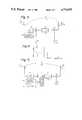
- FIG. 1is a block diagram of a prior booster
- FIG. 2is a block diagram of the prior apparatus for measuring the transmission loss between a transmitter antenna and a receiver antenna
- FIG. 3is a block diagram of the wireless repeater system according to the present invention.
- FIG. 4shows the spectrum of the signal applied to the signal detector 14 in FIG. 3, where f 1 is the receiver frequency and f 1 + ⁇ f is the offset received frequency,
- FIG. 5is another embodiment of the wireless repeater system according to the present invention.
- FIG. 6is still another embodiment of the wireless repeater system according to the present invention.
- FIG. 7is still another embodiment of the wireless repeater system according to the present invention.
- FIG. 8shows the experimental curves of the present invention
- FIG. 9is a block diagram of still another embodiment of the wireless repeater system according to the present invention.
- FIG. 10is a block diagram of the phase modulator 26 in FIG. 9,
- FIG. 11is a vector diagram which shows the operation of the phase modulator in FIG. 10,
- FIG. 12is a block diagram of still another embodiment of the wireless repeater system according to the present invention.
- FIG. 13is a block diagram of still another embodiment of the wireless repeater system according to the present invention.
- FIG. 14is a block diagram of the gain control in FIG. 13.
- FIG. 3is a block diagram of the first embodiment of the wireless repeater system or the booster according to the present invention.
- the numeral 1is a receiver antenna
- 3is a transmitter antenna
- 4is a received signal
- 5is a transmitted signal
- 6is a spillover signal from a transmitter antenna to a receiver antenna
- 9is a first mixer
- 10is a second mixer
- 11is a first local oscillator
- 12is a second local oscillator
- 13is a sampling means such as a directional coupler
- 14is a signal detector and 15 is an amplifier.
- the received signal in service with frequency f 1 and level A 1is received by the receiver antenna 1 which outputs the signal with level G 1 A 1 where G 1 is the gain of the receiver antenna 1.
- the received signalis frequency-converted by the first mixer 9 so that the output frequency of the mixer 9 is f IF , then, the intermediate frequency f IF is amplified by the amplifier 15 which has the gain G 15 .
- the output of the amplifier 15is applied to the second mixer 10 so that the intermediate frequency f IF is converted to the radio frequency f 1 with a small frequency shift ⁇ f. Therefore, the transmitted frequency from the transmitter antenna is f 1 + ⁇ f.
- That frequency difference ⁇ f between the receive frequency f 1 and the transmit frequency f 1 + ⁇ fis achieved by shifting the frequency of the second local oscillator 12 from that of the first local oscillator 11 so that the frequency of the first local oscillator 11 is f L , and the frequency of the second local oscillator 12 is f L + ⁇ f, where f L is f 1 -f IF .
- the level A 2 of the transmitted signal from the transmitter antenna 3is;
- G 4is the gain of the mixer 9
- G 5is the gain of the second mixer 10.
- G allis the total gain of the repeater, that is;
- a part of the transmitted signalleaks to the receiver antenna 1 as a spillover signal with the transmission loss L 5 between the transmitter antenna 3 and the receiver antenna 1.
- a part of the received signalis sampled by the directional coupler 13 which is located upstream of the first mixer 9, and the sampled signal is applied to the signal detector 14.
- the spectra of those two signalsare shown in FIG. 4.
- the received signal 4 in serviceis e i (A 1 cos 2 f 1 t)
- the spillover signal 6is e r (A r cos(2 f 1 t+2 ft)
- the input signal to the signal detector 14is e i +e r .
- the signal detector 14is simply implemented by using, for instance, an envelope detector. The output of the envelope detector of that signal is;
- the envelope of input signalshows a beat with frequency ⁇ f.
- the ratio of DC and AC elements of the envelopeis;
- the loop gain of spillover signalis directly obtained by measuring the beat of the input signal envelope.
- the offset frequency ⁇ fis selected so that it is higher than the fading frequency which is about 40 Hz (a case of 900 MHz radio frequency band and about 50 km/h mobile speed) depending upon the speed of a mobile which carries a telephone, and lower than the margin of a receiver. Still preferably, the offset frequency is lower than the 1/10 of the channel period. In a practical design, the offset frequency ⁇ f is selected around 50 Hz-200 Hz.
- the above embodimenthas the advantage that no particular measuring apparatus is necessary except for a booster itself, and the transmission loss is measured when the system is in service.
- FIG. 5shows the second embodiment of the present invention.
- the numerals 1 through 15are the same as those in FIG. 3, 16 is a control, and 17 is a variable attenuator.
- the control 16controls the variable attenuator 17 according to the transmission attenuation L 5 which is provided by the signal detector 14 so that the input level of the amplifier 15 is adjusted.
- the adjustment of the variable attenuator 17is equivalent to the adjustment of the gain of the amplifier 15.
- the transmission loss L 5 between the antennasis large, the attenuation in the variable attenuator 17 is adjusted to be small so that the gain of the repeater is large.
- the gain of the repeateris adjusted to be small so that the system does not oscillate.
- the gain of the repeatermay be the maximum within the range that the system does not oscillate.
- the gain of a repeateris smaller than that of the present invention, because the gain of the prior art is fixed to the value that the system is in the worst condition. So, even when the transmission loss is large in a prior art, the gain is not adaptively increased in a prior art.
- FIG. 6shows the third embodiment of the present invention.
- the numerals 1 through 15are the same as those in FIG. 3, and the numeral 16 is a control, 18 is a combiner, 19 is a sampling means such as a directional coupler, 20 is a variable phase shifter, 21 is a variable gain attenuator, and 22 is a delay circuit.
- the output of the second mixer 10is divided by the directional coupler 19.
- One output of the directional coupler 19is transmitted in the air through the transmission antenna 3, and the other output of the directional coupler 19 is applied through the variable phase shifter 20, the variable attenuator 21 and the delay circuit 22 to the combiner 18, which also receives the spillover signal 6, together with the reception service signal.
- the control 16controls the variable phase shifter 20, the variable attenuator 21 and the delay circuit 22 so that the output signal of the delay circuit 22 has the same level, the opposite phase and the same arrival time as those of the spillover signal 6, according to the measured result of the spillover signal by the detector 14. Then, the spillover signal is cancelled in the combiner 18.
- the embodiment of FIG. 6has the advantage that the gain of the booster is not restricted by a spillover signal.
- FIG. 7is the modification of the embodiment of FIG. 5.
- the feature of the FIG. 7is that the repeater operates in the radio frequency, while the embodiment of FIG. 5 converts the receive radio frequency to intermediate frequency (IF), which is amplified, then, re-converted to the radio frequency.
- IFintermediate frequency
- the amplifier 2operates in the radio frequency, therefore, no mixers (9 and 10 in FIG. 5), nor local oscillators (11 and 12 in FIG. 5) are provided in FIG. 7. Instead, the local oscillator 24 in FIG. 7 provides the offset frequency ⁇ f, which is applied to the frequency converter 25 which shifts the radio frequency by ⁇ f.
- the frequency converter 25 and the local oscillator 24 in FIG. 7are provided at the input of the amplifier 2.
- the frequency converter 25 and the local oscillator 24may be provided at the output of the amplifier 2. The location of those members does not effect to the operation of the repeater, since the whole system operates linearly to an input signal.
- FIG. 8shows the experimental curves of the present invention.
- the horizontal axisshows the loop gain for spillover signal. When that loop gain exceeds 0 dB, the system oscillates, therefore, that loop gain must be lower than 0 dB.
- the vertical axisshows the spillover signal detection level, and the booster output level.
- the booster outputis almost constant when the loop gain is less than -10 dB, and it increases suddenly and oscillates when the loop gain is close to 0 dB. It is shown that the spillover is accurately detected in the region where loop gain is -50 dB to 0 dB. In the experiment of FIG. 8, the booster gain is fixed to 50 dB.
- FIG. 9shows another embodiment of the present invention, and the feature of FIG. 9 is the use of a frequency converter made of an infinite phase shifter.
- the embodiment of FIG. 9has the advantage that the required accuracy of the local oscillator 11 is not as stringent when compared with the previous embodiments.
- the numerals 1 through 25are the same as those in FIG. 5, except that the amplifier 26 functions as a variable gain amplifier.
- the numeral 10is a second mixer, which takes the local oscillator 11, which is common both to the first mixer 9 and the second mixer 10. It should be appreciated of course that the mixers 9 and 10 together with the local oscillator 11 may be omitted if the amplifier 26 operates in the radio frequency as is the case of the embodiment of FIG. 7.
- the receive frequency f 1is converted to the intermediate frequency (IF) by the first mixer 9, and then, amplified by the variable gain amplifier 26, then, the output of the amplifier 26 is re-converted to the radio frequency f 1 by the second mixer 10.
- the frequency of the output of the second mixer 10is shifted by the frequency converter 25 by ⁇ f, which is transmitted through the transmission antenna 3.
- the operation of the directional coupler 13, the signal detector 14 and the control 16 for measuring the spillover signal and controlling the gain of the amplifieris the same as the previous embodiments.
- FIG. 10shows a block diagram of the frequency converter 25 or the infinite phase shifter.
- the numeral 32is a 90° hybrid circuit which divides an input signal to a pair of signals having the same amplitude and 90° phase difference with each other.
- the numerals 33a and 33bare 180° hybrid circuits each of which divides an input signal to a pair of outputs having the equal amplitude and 180° phase difference with each other.
- the numerals 34a, 34b, 34c and 34dare variable attenuators which are adjusted by a control signal.
- the input levels of the variable attenuators 34a through 34dare equal with one another, and the phase of each input signal to those variable attenuators is shifted by 90° with one another by the hybrid circuits 32, 33a and 33b, so that the input of the first attenuator 34a is 0°, the phase of the second attenuator 34b is 180°, the phase of the third attenuator 34c is 90°, and the phase of the fourth attenuator 34d is 270°.
- the numeral 35is a combiner for combining the outputs of the attenuators.
- the numerals 36a, 36b, 36c and 36dare phase shifters each of which shifts (leads) the low frequency signal of the oscillator 24 by 0°, 180°, 90°, and 270°, respectively.
- the outputs of the phase shifters 36a through 36dcontrol the variable attenuators 34a through 34d, respectively.
- FIG. 11shows the operation of the frequency converter of FIG. 10.
- the output vectors of the attenuators 34a and 34bare located on the line 0°-180° with opposite phase with each other, and the composite vector of the two vectors vibration as simple harmonic motion.
- the vectors of the attenuators 34c and 34dare located on the line 90°-270° with opposite phases from each other, and the composite vector of the two vectors vibrate in a simple harmonic motion. Therefore, the vectors of the attenuators 34a and 34b, has the phase difference by 90° as compared with that of the attenuators 34c and 34d.
- the combination of the vectors of the four attenuators in the combiner 35provides a vector which rotates on a unit circle by 360° for each cycle of the output signal ⁇ f of the low frequency oscillator 24.
- the transmission frequency f 1 + ⁇ fis obtained at the output of the frequency converter 25 in FIG. 9 by using the offset low frequency ⁇ f, and the radio frequency is directly shifted by ⁇ f.
- FIGS. 12 and 13show still another embodiment of the present invention, and the feature of the embodiment is that a plurality of radio channels are amplified by a single common amplifier, and that the gain of the amplifier is controlled for each channel.
- This embodimentis advantageous when the transmission loss or the spillover signal has the frequency characteristics.
- FIG. 12is the embodiment that the amplification for each channel is accomplished in the intermediate frequency stage
- FIG. 13is the embodiment that the amplification for each channel is accomplished in the radio frequency stage.
- the numeral 1is a receiver antenna
- 3is a transmitter antenna
- 4is a received signal
- 5is a transmitted signal
- 6is a spillover signal
- 13is a directional coupler
- 40is a variable gain amplifier or a variable attenuator
- 25is a frequency converter
- 2is a fixed gain amplifier
- 46is a mixer
- 48is a bandpass filter for deriving IF signal for each channel
- 50is a signal detector which is similar to that of FIG. 5, 16 is a control, 24 is an offset frequency oscillator.
- the control 16switches the local frequency of the local oscillator 52 so that desired frequency band is obtained at the output of the mixer 46, the output of which is applied to the detector 50 through the bandpass filter 48.
- the detector 50detects the spillover signal by detecting the offset frequency component ( ⁇ f) as is the case of the previous embodiments, and the result of the detection for each band is applied to the control 16.
- the control 16sends the control signal to the variable gain amplifier 40 so that the gain for the current measured band is adjusted according to the current spillover signal level.
- the gain of the repeateris adjusted so that it is optimum for each band.
- the loop gain of the spillover signalis uniform for all the bands, and all the bands can have the maximum gain keeping the predetermined margin for oscillation.
- variable gain amplifier 40the total gain by the variable gain amplifier 40 and the fixed gain amplifier 2 is variable.
- variable gain amplifier 40the frequency converter 25 and the amplifier 2
- the amplifier 2may be located at the input of the frequency converter 25, although the embodiment locates the same at the output of the frequency converter 25.
- FIG. 13is the modification of FIG. 12, and the feature of FIG. 13 is that the detection of the spillover signal by the detector 50 is accomplished in the radio frequency, while FIG. 12 detects the same in the IF frequency band.
- the numeral 60is a plurality of bandpass filters
- 62is a switch for selecting one of the outputs of the bandpass filters 60.
- the control 16controls the switch 62 so that the reception frequency bands are scanned, and controls the gain (or attenuation) of the gain control 40 for the selected band.
- FIG. 14is a block diagram of the gain control which is used as the variable gain amplifier 40 (or a variable attenuator) in FIG. 12 and 13.
- the numeral 70is a plurality of bandpass filters coupled with the directional coupler 13
- 72is a plurality of attenuators which are controlled by the control 16
- the numeral 74is a plurality of bandpass filters coupled with the frequency converter 10.
- the bandpass filters 70divide the frequency band of the input signal to a plurality of narrow bands. Each bandwidth of the output of the filter 70 is designed so that the frequency characteristics of the spillover signal is flat in that band, and that band corresponds to the band of the filter 60 in FIG. 13.
- variable gain amplifier 72are provided for each band relating outputs of the filter 70, and are controlled by the control 16 so that the gain of the repeater in each band is the optimum depending upon the spillover level of each band.
- the filter 74has the similar configuration to that of the filter 70, and combines the outputs of the variable gain amplifier 72 so that the combined signal is coupled with the frequency converter 25. Thus, by using the gain control of FIG. 14, the gain of the repeater is controlled for each frequency band.
Landscapes
- Engineering & Computer Science (AREA)
- Computer Networks & Wireless Communication (AREA)
- Signal Processing (AREA)
- Radio Relay Systems (AREA)
Abstract
Description
L.sub.5 =(A.sub.1 /A.sub.0)×G.sub.1 ×G.sub.2 ×G.sub.3
A.sub.2 =A.sub.1 ×G.sub.1 ×G.sub.15 ×G.sub.3 ×G.sub.4 ×G.sub.5
G.sub.all =G.sub.1 ×G.sub.15 ×G.sub.3 ×G.sub.4 ×G.sub.4 ×G.sub.5
(A.sub.1.sup.2 +2A.sub.1 A.sub.r cos 2 Δft+A.sub.r.sup.2).sup.1/2
A.sub.1 +A.sub.r cos 2 Δft
A.sub.r /A.sub.1 =A.sub.2 /(L.sub.5 ×A.sub.1)=G.sub.all /L.sub.5
Claims (10)
Applications Claiming Priority (6)
| Application Number | Priority Date | Filing Date | Title |
|---|---|---|---|
| JP61-111088 | 1985-05-15 | ||
| JP60-281219 | 1985-12-16 | ||
| JP60281219AJPH0695654B2 (en) | 1985-12-16 | 1985-12-16 | Wireless repeater |
| JP11108886AJPH06105881B2 (en) | 1986-05-15 | 1986-05-15 | Wireless repeater |
| JP61-223496 | 1986-09-24 | ||
| JP22349686AJPH0652881B2 (en) | 1986-09-24 | 1986-09-24 | Wireless repeater |
Publications (1)
| Publication Number | Publication Date |
|---|---|
| US4776032Atrue US4776032A (en) | 1988-10-04 |
Family
ID=27311883
Family Applications (1)
| Application Number | Title | Priority Date | Filing Date |
|---|---|---|---|
| US06/940,134Expired - LifetimeUS4776032A (en) | 1985-05-15 | 1986-12-10 | Repeater for a same frequency with spillover measurement |
Country Status (3)
| Country | Link |
|---|---|
| US (1) | US4776032A (en) |
| EP (1) | EP0227393B1 (en) |
| DE (1) | DE3650241T2 (en) |
Cited By (82)
| Publication number | Priority date | Publication date | Assignee | Title |
|---|---|---|---|---|
| US5095528A (en)* | 1988-10-28 | 1992-03-10 | Orion Industries, Inc. | Repeater with feedback oscillation control |
| US5115514A (en)* | 1987-08-03 | 1992-05-19 | Orion Industries, Inc. | Measuring and controlling signal feedback between the transmit and receive antennas of a communications booster |
| US5230097A (en)* | 1990-03-09 | 1993-07-20 | Scientific-Atlanta, Inc. | Offset frequency converter for phase/amplitude data measurement receivers |
| US5369782A (en)* | 1990-08-22 | 1994-11-29 | Mitsubishi Denki Kabushiki Kaisha | Radio relay system, including interference signal cancellation |
| US5471642A (en)* | 1994-01-28 | 1995-11-28 | Palmer; James K. | Re-broadcast system for a plurality of AM signals |
| WO1997033381A1 (en)* | 1996-03-04 | 1997-09-12 | Allgon Ab | A method and device for monitoring a mobile telephone repeater |
| US5963847A (en)* | 1995-10-26 | 1999-10-05 | Ntt Mobile Communications Network Inc. | Booster system |
| US6011962A (en)* | 1996-05-07 | 2000-01-04 | Fuba Automotive Gmbh | Circuit for testing the function of mobile receiving installations |
| EP0957587A3 (en)* | 1998-05-13 | 2000-04-05 | Lucent Technologies Inc. | Method and apparatus to reduce transmitter overload in a transmit scanning receiver |
| EP1039716A1 (en)* | 1999-03-25 | 2000-09-27 | Kabushiki Kaisha Toshiba | OFDM transmission signal repeater and receiver |
| WO2000077941A1 (en)* | 1999-06-11 | 2000-12-21 | Allgon Ab | Method and apparatus for stability margin determination in a repeater |
| EP0920126A3 (en)* | 1997-11-26 | 2001-01-17 | Deutsche Telekom AG | Method and apparatus for adaptively controlling the gain of an amplifier |
| EP1056198A3 (en)* | 1999-05-25 | 2001-01-31 | Deutsche Telekom AG | Circuitry and Method of Adaptive Control of the Gain of a Feedback Amplifier |
| KR20010088138A (en)* | 2000-03-10 | 2001-09-26 | 조태영 | Radio relay system having a turnaround wave sense circuit |
| US6336042B1 (en)* | 1998-06-05 | 2002-01-01 | Transcept, Inc. | Reverse link antenna diversity in a wireless telephony system |
| US20020045431A1 (en)* | 2000-10-18 | 2002-04-18 | Spotwave Wireless Inc. | Intelligent gain control in an on-frequency repeater |
| US20020127968A1 (en)* | 2001-03-06 | 2002-09-12 | Matsushita Electric Industrial Co., Ltd. | Relay apparatus |
| US6493537B1 (en)* | 1999-03-31 | 2002-12-10 | Harada Industry Co., Ltd. | Apparatus and method for preventing oscillations in a radio repeater device |
| US6832075B1 (en)* | 1999-10-05 | 2004-12-14 | Ericsson Inc. | Method for calibrating the power output of a mobile device |
| US20060189276A1 (en)* | 2004-12-08 | 2006-08-24 | Michael Halinski | Methods and systems for intelligent adaptive gain control |
| US20080113638A1 (en)* | 2006-11-15 | 2008-05-15 | Michael Thomas Curtin | Controlled signal-to-noise ratio generator circuit |
| US20080225929A1 (en)* | 2007-03-02 | 2008-09-18 | Qualcomm Incorporated | Closed Form Calculation of Temporal Equalizer Weights Used in a Repeater Transmitter Leakage Cancellation System |
| US20100167639A1 (en)* | 2008-12-31 | 2010-07-01 | Chris Ranson | System and method for feedback cancellation in repeaters |
| US20110143658A1 (en)* | 2009-12-11 | 2011-06-16 | Van Hanson | System and method for determining and controlling gain margin in an rf repeater |
| US20140194054A1 (en)* | 2013-01-08 | 2014-07-10 | Advanced Rf Technologies, Inc. | Mobile telecommunication repeater for canceling feedback signals |
| US9602148B2 (en) | 2013-04-30 | 2017-03-21 | Novero Dabendorf Gmbh | Compensation for a signal damping while transmitting transmission signals of a wireless mobile device |
| US10056966B2 (en) | 2013-05-30 | 2018-08-21 | Advanced Rf Technologies, Inc. | Interference cancellation repeater and repeating method |
| US10148341B2 (en) | 2017-02-02 | 2018-12-04 | Wilson Electronics, Llc | Independent band detection for network protection |
| US10153826B2 (en) | 2015-11-17 | 2018-12-11 | Wilson Electronics, Llc | Cellular signal booster with multiple signal chains |
| US10212716B2 (en) | 2015-10-14 | 2019-02-19 | Wilson Electronics, Llc | Channelization for signal boosters |
| US10251127B2 (en) | 2015-08-18 | 2019-04-02 | Wilson Electronics, Llc | Wireless device signal amplifier |
| US10348392B2 (en) | 2016-11-15 | 2019-07-09 | Wilson Electronics, Llc | Desktop signal booster |
| US10356732B2 (en) | 2016-04-05 | 2019-07-16 | Wilson Electronics, Llc | Narrowband signal detection for network protection |
| US10374698B2 (en) | 2017-01-31 | 2019-08-06 | Wilson Electronics, Llc | Reducing oscillation in a signal booster |
| US10389430B2 (en) | 2016-10-07 | 2019-08-20 | Wilson Electronics, Llc | Multi-amplifier booster for a wireless communication system |
| US10424822B2 (en) | 2015-10-14 | 2019-09-24 | Wilson Electronics, Llc | Multi-common port multiband filters |
| US10432294B2 (en) | 2017-02-02 | 2019-10-01 | Wilson Electronics, Llc | Signal booster with spectrally adjacent bands |
| US10432332B2 (en) | 2016-10-07 | 2019-10-01 | Wilson Electronics, Llc | Narrowband signal detection |
| US10485057B2 (en) | 2017-04-11 | 2019-11-19 | Wilson Electronics, Llc | Signal booster with coaxial cable connections |
| US10523160B2 (en) | 2017-08-31 | 2019-12-31 | Wilson Electronics, Llc | Protection of power amplifiers in a signal booster |
| US10523305B2 (en) | 2017-05-11 | 2019-12-31 | Wilson Electronics, Llc | Variable channelized bandwidth booster |
| US10585460B2 (en) | 2017-06-16 | 2020-03-10 | Wilson Electronics, Llc | Pole integrated repeater system |
| US10630374B2 (en) | 2017-04-06 | 2020-04-21 | Wilson Electronics, Llc | Allocating and adjusting power between active ports of a multi-port booster |
| US10637557B2 (en) | 2017-04-07 | 2020-04-28 | Wilson Electronics, Llc | Multi-amplifier repeater system for wireless communication |
| US10644790B2 (en) | 2016-09-23 | 2020-05-05 | Wilson Electronics, Llc | Booster with an integrated satellite location system module |
| US10659142B1 (en) | 2018-12-04 | 2020-05-19 | Wilson Electronics, Llc | Independent band detection for network protection |
| US10674526B2 (en) | 2016-09-23 | 2020-06-02 | Wilson Electronics, Llc | Location based access to selected communication bands |
| US10673518B2 (en) | 2017-06-27 | 2020-06-02 | Wilson Electronics, Llc | Crossover isolation reduction in a signal booster |
| US10673517B2 (en) | 2016-11-15 | 2020-06-02 | Wilson Electronics, Llc | Desktop signal booster |
| US10715302B2 (en) | 2015-10-14 | 2020-07-14 | Wilson Electronics, Llc | Channelization for signal boosters |
| US10715244B2 (en) | 2017-12-29 | 2020-07-14 | Wilson Electronics, Llc | Signal booster with balanced gain control |
| US10855363B2 (en) | 2018-05-07 | 2020-12-01 | Wilson Electronics, Llc | Multiple-input multiple-output (MIMO) repeater system |
| US10862533B2 (en) | 2018-01-04 | 2020-12-08 | Wilson Electronics, Llc | Line loss detection in a signal booster system |
| US10862529B2 (en) | 2015-08-18 | 2020-12-08 | Wilson Electronics, Llc | Separate uplink and downlink antenna repeater architecture |
| US20200389142A1 (en)* | 2019-06-05 | 2020-12-10 | Wilson Electronics, Llc | Power amplifier (pa)-filter output power tuning |
| US10873387B2 (en) | 2017-02-02 | 2020-12-22 | Wilson Electronics, Llc | Signal booster with spectrally adjacent bands |
| US10879995B2 (en) | 2018-04-10 | 2020-12-29 | Wilson Electronics, Llc | Feedback cancellation on multiband booster |
| US10897070B2 (en) | 2018-08-01 | 2021-01-19 | Wilson Electronics, Llc | Connect RV mount |
| US10979130B2 (en) | 2017-02-09 | 2021-04-13 | Wilson Electronics, Llc | Amplification adjustment techniques for a wireless repeater |
| US11031994B2 (en) | 2016-11-15 | 2021-06-08 | Wilson Electronics, Llc | Signal booster for boosting signals in contiguous bands |
| US11031995B2 (en) | 2019-05-15 | 2021-06-08 | Wilson Electronics, Llc | Multi-use booster |
| US11038542B2 (en) | 2018-12-31 | 2021-06-15 | Wilson Electronics, Llc | Active multiplexer repeater accessory |
| US11201664B2 (en) | 2019-04-29 | 2021-12-14 | Wilson Electronics, Llc | Adjusting repeater gain based on antenna feedback path loss |
| US11218237B2 (en) | 2018-09-27 | 2022-01-04 | Wilson Electronics, Llc | Intermediate frequency (IF) filtering for enhanced crossover attenuation in a repeater |
| US11223415B2 (en) | 2019-05-24 | 2022-01-11 | Wilson Electronics, Llc | Repeater with low power mode for mobile operations |
| US20220109493A1 (en)* | 2019-04-29 | 2022-04-07 | Wilson Electronics, Llc | Adjusting Repeater Gain Based on Antenna Feedback Path Loss |
| US11303369B2 (en) | 2018-10-09 | 2022-04-12 | Wilson Electronics, Llc | Booster gain adjustment based on user equipment (UE) need |
| US11362798B2 (en) | 2018-09-07 | 2022-06-14 | Wilson Electronics, Llc | Channelization options for reducing network sensitivity |
| US11362729B2 (en) | 2020-07-01 | 2022-06-14 | Wilson Electronics, Llc | Pre-amplifier for a modem |
| US11387893B2 (en) | 2019-12-31 | 2022-07-12 | Wilson Electronics, Llc | Repeater with carrier-specific information |
| US11418253B2 (en) | 2018-12-31 | 2022-08-16 | Wilson Electronics, Llc | Time division duplex (TDD) repeater configured to communicate with a spectrum access system (SAS) |
| US11418251B2 (en) | 2020-05-22 | 2022-08-16 | Wilson Electronics, Llc | Signal booster for spectrally adjacent bands |
| US11527898B2 (en) | 2018-02-21 | 2022-12-13 | Wilson Electronics, Llc | Wireless device cradles |
| US11601187B2 (en) | 2019-04-17 | 2023-03-07 | Wilson Electronics, Llc | Carrier-aggregation repeater |
| US11627482B2 (en) | 2018-04-19 | 2023-04-11 | Wilson Electronics, Llc | Repeater with integrated modem for remote monitoring |
| US11705958B2 (en) | 2020-07-10 | 2023-07-18 | Wilson Electronics, Llc | Software-defined filtering in a repeater |
| US11742931B2 (en) | 2020-06-26 | 2023-08-29 | Wilson Electronics, Llc | Time division duplex (TDD) network protection repeater |
| US11894910B2 (en) | 2018-12-31 | 2024-02-06 | Wilson Electronics, Llc | Cellular and public safety repeater |
| US12052086B2 (en) | 2019-04-01 | 2024-07-30 | Wilson Electronics, Llc | Combined duplexer |
| US12120620B2 (en) | 2019-05-29 | 2024-10-15 | Wilson Electronics, Llc | Multiplex time division duplex (TDD) sync detection module |
| US12191972B2 (en) | 2020-08-06 | 2025-01-07 | Wilson Electronics, Llc | Multiband repeater architecture |
| US12218738B2 (en) | 2019-12-31 | 2025-02-04 | Wilson Electronics, Llc | Repeater with carrier-specific information |
Families Citing this family (9)
| Publication number | Priority date | Publication date | Assignee | Title |
|---|---|---|---|---|
| GB2258586B (en)* | 1991-08-05 | 1995-05-10 | Mercury Personal Communication | Radio signal enhancer |
| GB9423027D0 (en) | 1994-11-15 | 1995-01-04 | Univ Bristol | Full-duplex radio transmitter/receiver |
| GB9522198D0 (en)* | 1995-10-30 | 1996-01-03 | British Broadcasting Corp | Ofdm active deflectors |
| US5835848A (en)* | 1996-12-30 | 1998-11-10 | Lucent Technologies Inc. | Range repeater for a transmission system |
| KR100331786B1 (en)* | 1999-08-31 | 2002-04-17 | 이돈신 | Frequency conversion relay system in series type |
| US7123676B2 (en)* | 2003-11-17 | 2006-10-17 | Quellan, Inc. | Method and system for antenna interference cancellation |
| GB0510385D0 (en) | 2005-05-20 | 2005-06-29 | British Broadcasting Corp | Improvements relating to on-channel repeaters |
| WO2007087649A1 (en)* | 2006-01-27 | 2007-08-02 | Qualcomm Incorporated | Repeater open loop gain measurement |
| US9215019B2 (en) | 2012-02-13 | 2015-12-15 | Alcatel Lucent | Method and apparatus for interference cancellation in hybrid satellite-terrestrial network |
Citations (9)
| Publication number | Priority date | Publication date | Assignee | Title |
|---|---|---|---|---|
| US3448383A (en)* | 1967-08-02 | 1969-06-03 | Bendix Corp | Single frequency communication repeater |
| US3696429A (en)* | 1971-05-24 | 1972-10-03 | Cutler Hammer Inc | Signal cancellation system |
| GB2065421A (en)* | 1979-06-08 | 1981-06-24 | Plessey Co Ltd | Improvements in or relating to duplex transceivers |
| US4317217A (en)* | 1980-08-11 | 1982-02-23 | Motorola, Inc. | Tag generator for a same-frequency repeater |
| US4383331A (en)* | 1981-07-02 | 1983-05-10 | Motorola, Inc. | Method and means of preventing oscillations in a same-frequency repeater |
| US4475243A (en)* | 1982-12-21 | 1984-10-02 | Motorola, Inc. | Isolation method and apparatus for a same frequency repeater |
| US4475246A (en)* | 1982-12-21 | 1984-10-02 | Motorola, Inc. | Simulcast same frequency repeater system |
| US4493111A (en)* | 1981-12-18 | 1985-01-08 | Thomson-Csf | Electronic antenna decoupling process and device |
| US4725842A (en)* | 1982-09-27 | 1988-02-16 | Teledyne Industries, Inc. | Isolation apparatus for a continuous-wave radar system |
Family Cites Families (8)
| Publication number | Priority date | Publication date | Assignee | Title |
|---|---|---|---|---|
| US1397093A (en)* | 1919-09-27 | 1921-11-15 | American Telephone & Telegraph | Radiorepeating system |
| US2106806A (en)* | 1936-07-08 | 1938-02-01 | Rca Corp | Relay system |
| GB613854A (en)* | 1946-01-21 | 1948-12-03 | Gen Electric Co Ltd | Improvements in and relating to repeater systems for high frequency electric waves |
| US3611139A (en)* | 1970-02-25 | 1971-10-05 | Us Navy | Orthogonal mixer f{11 {0 f{11 {0 repeater |
| JPS4929921A (en) | 1972-07-20 | 1974-03-16 | ||
| DE2729013C2 (en)* | 1977-06-28 | 1986-08-21 | Licentia Patent-Verwaltungs-Gmbh, 6000 Frankfurt | Single frequency transceiver |
| JPS5466025A (en) | 1977-11-05 | 1979-05-28 | Matsushita Electric Ind Co Ltd | Preventing device for oscillation of television receiving booster |
| JPS60186133A (en)* | 1984-03-06 | 1985-09-21 | Toyo Commun Equip Co Ltd | Automatic repeating system |
- 1986
- 1986-12-10USUS06/940,134patent/US4776032A/ennot_activeExpired - Lifetime
- 1986-12-12EPEP86309705Apatent/EP0227393B1/ennot_activeExpired - Lifetime
- 1986-12-12DEDE3650241Tpatent/DE3650241T2/ennot_activeExpired - Lifetime
Patent Citations (9)
| Publication number | Priority date | Publication date | Assignee | Title |
|---|---|---|---|---|
| US3448383A (en)* | 1967-08-02 | 1969-06-03 | Bendix Corp | Single frequency communication repeater |
| US3696429A (en)* | 1971-05-24 | 1972-10-03 | Cutler Hammer Inc | Signal cancellation system |
| GB2065421A (en)* | 1979-06-08 | 1981-06-24 | Plessey Co Ltd | Improvements in or relating to duplex transceivers |
| US4317217A (en)* | 1980-08-11 | 1982-02-23 | Motorola, Inc. | Tag generator for a same-frequency repeater |
| US4383331A (en)* | 1981-07-02 | 1983-05-10 | Motorola, Inc. | Method and means of preventing oscillations in a same-frequency repeater |
| US4493111A (en)* | 1981-12-18 | 1985-01-08 | Thomson-Csf | Electronic antenna decoupling process and device |
| US4725842A (en)* | 1982-09-27 | 1988-02-16 | Teledyne Industries, Inc. | Isolation apparatus for a continuous-wave radar system |
| US4475243A (en)* | 1982-12-21 | 1984-10-02 | Motorola, Inc. | Isolation method and apparatus for a same frequency repeater |
| US4475246A (en)* | 1982-12-21 | 1984-10-02 | Motorola, Inc. | Simulcast same frequency repeater system |
Non-Patent Citations (4)
| Title |
|---|
| Anaren, Microwave Components Catalog.* |
| Cell Enhancer: Beyond the Outer Limits, Cellular Business, Rosenbloom et al, Kuly, 1986, pp. 40 and 42.* |
| The Cell Enhancer, IEEE, Quinn, 1986, pp. 77 83.* |
| The Cell Enhancer, IEEE, Quinn, 1986, pp. 77-83. |
Cited By (123)
| Publication number | Priority date | Publication date | Assignee | Title |
|---|---|---|---|---|
| US5115514A (en)* | 1987-08-03 | 1992-05-19 | Orion Industries, Inc. | Measuring and controlling signal feedback between the transmit and receive antennas of a communications booster |
| US5095528A (en)* | 1988-10-28 | 1992-03-10 | Orion Industries, Inc. | Repeater with feedback oscillation control |
| US5230097A (en)* | 1990-03-09 | 1993-07-20 | Scientific-Atlanta, Inc. | Offset frequency converter for phase/amplitude data measurement receivers |
| US5369782A (en)* | 1990-08-22 | 1994-11-29 | Mitsubishi Denki Kabushiki Kaisha | Radio relay system, including interference signal cancellation |
| US5471642A (en)* | 1994-01-28 | 1995-11-28 | Palmer; James K. | Re-broadcast system for a plurality of AM signals |
| US5963847A (en)* | 1995-10-26 | 1999-10-05 | Ntt Mobile Communications Network Inc. | Booster system |
| WO1997033381A1 (en)* | 1996-03-04 | 1997-09-12 | Allgon Ab | A method and device for monitoring a mobile telephone repeater |
| US6009324A (en)* | 1996-03-04 | 1999-12-28 | Allgon Ab | Method and device for monitoring a mobile telephone repeater |
| US6011962A (en)* | 1996-05-07 | 2000-01-04 | Fuba Automotive Gmbh | Circuit for testing the function of mobile receiving installations |
| EP0920126A3 (en)* | 1997-11-26 | 2001-01-17 | Deutsche Telekom AG | Method and apparatus for adaptively controlling the gain of an amplifier |
| EP0957587A3 (en)* | 1998-05-13 | 2000-04-05 | Lucent Technologies Inc. | Method and apparatus to reduce transmitter overload in a transmit scanning receiver |
| US6336042B1 (en)* | 1998-06-05 | 2002-01-01 | Transcept, Inc. | Reverse link antenna diversity in a wireless telephony system |
| EP1039716A1 (en)* | 1999-03-25 | 2000-09-27 | Kabushiki Kaisha Toshiba | OFDM transmission signal repeater and receiver |
| US6493537B1 (en)* | 1999-03-31 | 2002-12-10 | Harada Industry Co., Ltd. | Apparatus and method for preventing oscillations in a radio repeater device |
| EP1056198A3 (en)* | 1999-05-25 | 2001-01-31 | Deutsche Telekom AG | Circuitry and Method of Adaptive Control of the Gain of a Feedback Amplifier |
| WO2000077941A1 (en)* | 1999-06-11 | 2000-12-21 | Allgon Ab | Method and apparatus for stability margin determination in a repeater |
| US6745007B1 (en) | 1999-06-11 | 2004-06-01 | Allgon, Ab | Method and apparatus for stability margin determination in a repeater |
| US7398053B2 (en) | 1999-06-11 | 2008-07-08 | Allgon Ab | Method and apparatus for stability margin determination in a repeater |
| US6832075B1 (en)* | 1999-10-05 | 2004-12-14 | Ericsson Inc. | Method for calibrating the power output of a mobile device |
| KR20010088138A (en)* | 2000-03-10 | 2001-09-26 | 조태영 | Radio relay system having a turnaround wave sense circuit |
| US6889033B2 (en)* | 2000-10-18 | 2005-05-03 | Spotwave Wireless Inc. | Intelligent gain control in an on-frequency repeater |
| US20020045431A1 (en)* | 2000-10-18 | 2002-04-18 | Spotwave Wireless Inc. | Intelligent gain control in an on-frequency repeater |
| US20020127968A1 (en)* | 2001-03-06 | 2002-09-12 | Matsushita Electric Industrial Co., Ltd. | Relay apparatus |
| EP1239610A3 (en)* | 2001-03-06 | 2006-01-04 | Matsushita Electric Industrial Co., Ltd. | Repeater apparatus comprising a means for canceling loop feedback between a reception and a transmission antenna |
| US7046960B2 (en) | 2001-03-06 | 2006-05-16 | Matsushita Electric Industrial Co., Ltd. | Relay apparatus |
| US20060189276A1 (en)* | 2004-12-08 | 2006-08-24 | Michael Halinski | Methods and systems for intelligent adaptive gain control |
| US20080113638A1 (en)* | 2006-11-15 | 2008-05-15 | Michael Thomas Curtin | Controlled signal-to-noise ratio generator circuit |
| US7634236B2 (en)* | 2006-11-15 | 2009-12-15 | Northrop Grumman Corporation | Controlled signal-to-noise ratio generator circuit |
| US8619837B2 (en) | 2007-03-02 | 2013-12-31 | Qualcomm Incorporated | Use of adaptive antenna array in conjunction with an on-channel repeater to improve signal quality |
| US8599906B2 (en) | 2007-03-02 | 2013-12-03 | Qualcomm Incorporated | Closed form calculation of temporal equalizer weights used in a repeater transmitter leakage cancellation system |
| US20080311848A1 (en)* | 2007-03-02 | 2008-12-18 | Qualcomm Incorporated | Configuration of a Repeater |
| US20080225931A1 (en)* | 2007-03-02 | 2008-09-18 | Qualcomm Incorporated | Use of Adaptive Antenna Array in Conjunction with an On-Channel Repeater to Improve Signal Quality |
| US20080225930A1 (en)* | 2007-03-02 | 2008-09-18 | Qualcomm Incorporated | Use of a Filterbank in an Adaptive On-Channel Repeater Utilizing Adaptive Antenna Arrays |
| US20080225929A1 (en)* | 2007-03-02 | 2008-09-18 | Qualcomm Incorporated | Closed Form Calculation of Temporal Equalizer Weights Used in a Repeater Transmitter Leakage Cancellation System |
| US8116239B2 (en) | 2007-03-02 | 2012-02-14 | Qualcomm Incorporated | Use of a filterbank in an adaptive on-channel repeater utilizing adaptive antenna arrays |
| US8121535B2 (en) | 2007-03-02 | 2012-02-21 | Qualcomm Incorporated | Configuration of a repeater |
| US8135339B2 (en) | 2008-12-31 | 2012-03-13 | Andrew Llc | System and method for feedback cancellation in repeaters |
| US8351851B2 (en) | 2008-12-31 | 2013-01-08 | Andrew Llc | System and method for feedback cancellation in repeaters |
| US8571470B2 (en) | 2008-12-31 | 2013-10-29 | Andrew Llc | System and method for feedback cancellation in repeaters |
| US20100167639A1 (en)* | 2008-12-31 | 2010-07-01 | Chris Ranson | System and method for feedback cancellation in repeaters |
| USRE47075E1 (en)* | 2009-12-11 | 2018-10-02 | Commscope Technologies Llc | System and method for determining and controlling gain margin in an RF repeater |
| US8948687B2 (en)* | 2009-12-11 | 2015-02-03 | Andrew Llc | System and method for determining and controlling gain margin in an RF repeater |
| US20110143658A1 (en)* | 2009-12-11 | 2011-06-16 | Van Hanson | System and method for determining and controlling gain margin in an rf repeater |
| US20140194054A1 (en)* | 2013-01-08 | 2014-07-10 | Advanced Rf Technologies, Inc. | Mobile telecommunication repeater for canceling feedback signals |
| US10305575B2 (en)* | 2013-01-08 | 2019-05-28 | Advanced Rf Technologies, Inc. | Mobile telecommunication repeater for canceling feedback signals |
| US9602148B2 (en) | 2013-04-30 | 2017-03-21 | Novero Dabendorf Gmbh | Compensation for a signal damping while transmitting transmission signals of a wireless mobile device |
| US10056966B2 (en) | 2013-05-30 | 2018-08-21 | Advanced Rf Technologies, Inc. | Interference cancellation repeater and repeating method |
| US10862529B2 (en) | 2015-08-18 | 2020-12-08 | Wilson Electronics, Llc | Separate uplink and downlink antenna repeater architecture |
| US11223384B2 (en) | 2015-08-18 | 2022-01-11 | Wilson Electronics, Llc | Low noise signal chain architecture |
| US10251127B2 (en) | 2015-08-18 | 2019-04-02 | Wilson Electronics, Llc | Wireless device signal amplifier |
| US10424822B2 (en) | 2015-10-14 | 2019-09-24 | Wilson Electronics, Llc | Multi-common port multiband filters |
| US10715302B2 (en) | 2015-10-14 | 2020-07-14 | Wilson Electronics, Llc | Channelization for signal boosters |
| US10212716B2 (en) | 2015-10-14 | 2019-02-19 | Wilson Electronics, Llc | Channelization for signal boosters |
| US10847856B2 (en) | 2015-10-14 | 2020-11-24 | Wilson Electronics, Llc | Multi-common port multiband filters |
| US11539498B2 (en) | 2015-10-14 | 2022-12-27 | Wilson Electronics, Llc | Channelization for signal boosters |
| US10225845B2 (en) | 2015-10-14 | 2019-03-05 | Wilson Electronics, Llc | Channelization for signal boosters |
| US10153826B2 (en) | 2015-11-17 | 2018-12-11 | Wilson Electronics, Llc | Cellular signal booster with multiple signal chains |
| US10630372B2 (en) | 2015-11-17 | 2020-04-21 | Wilson Electronics, Llc | Cellular signal booster with redundant paths for the same selected band |
| US10356732B2 (en) | 2016-04-05 | 2019-07-16 | Wilson Electronics, Llc | Narrowband signal detection for network protection |
| US10644790B2 (en) | 2016-09-23 | 2020-05-05 | Wilson Electronics, Llc | Booster with an integrated satellite location system module |
| US10674526B2 (en) | 2016-09-23 | 2020-06-02 | Wilson Electronics, Llc | Location based access to selected communication bands |
| US11102801B2 (en) | 2016-09-23 | 2021-08-24 | Wilson Electronics, Llc | Location based access to selected communication bands |
| US10432332B2 (en) | 2016-10-07 | 2019-10-01 | Wilson Electronics, Llc | Narrowband signal detection |
| US10389430B2 (en) | 2016-10-07 | 2019-08-20 | Wilson Electronics, Llc | Multi-amplifier booster for a wireless communication system |
| US10805026B2 (en) | 2016-10-07 | 2020-10-13 | Wilson Electronics, Llc | Narrowband signal detection |
| US10348392B2 (en) | 2016-11-15 | 2019-07-09 | Wilson Electronics, Llc | Desktop signal booster |
| US10673517B2 (en) | 2016-11-15 | 2020-06-02 | Wilson Electronics, Llc | Desktop signal booster |
| US10992371B2 (en) | 2016-11-15 | 2021-04-27 | Wilson Electronics, Llc | Desktop signal booster |
| US11012143B2 (en) | 2016-11-15 | 2021-05-18 | Wilson Electronics, Llc | Desktop signal booster |
| US11095359B2 (en) | 2016-11-15 | 2021-08-17 | Wilson Electronics, Llc | Multiple antenna repeater architecture |
| US12063094B2 (en) | 2016-11-15 | 2024-08-13 | Wilson Electronics, Llc | Desktop signal booster |
| US11031994B2 (en) | 2016-11-15 | 2021-06-08 | Wilson Electronics, Llc | Signal booster for boosting signals in contiguous bands |
| US10374698B2 (en) | 2017-01-31 | 2019-08-06 | Wilson Electronics, Llc | Reducing oscillation in a signal booster |
| US10432294B2 (en) | 2017-02-02 | 2019-10-01 | Wilson Electronics, Llc | Signal booster with spectrally adjacent bands |
| US10630371B2 (en) | 2017-02-02 | 2020-04-21 | Wilson Electronics, Llc | Signal booster with spectrally adjacent bands |
| US10148341B2 (en) | 2017-02-02 | 2018-12-04 | Wilson Electronics, Llc | Independent band detection for network protection |
| US10873387B2 (en) | 2017-02-02 | 2020-12-22 | Wilson Electronics, Llc | Signal booster with spectrally adjacent bands |
| US10979130B2 (en) | 2017-02-09 | 2021-04-13 | Wilson Electronics, Llc | Amplification adjustment techniques for a wireless repeater |
| US10630374B2 (en) | 2017-04-06 | 2020-04-21 | Wilson Electronics, Llc | Allocating and adjusting power between active ports of a multi-port booster |
| US10637557B2 (en) | 2017-04-07 | 2020-04-28 | Wilson Electronics, Llc | Multi-amplifier repeater system for wireless communication |
| US10512120B2 (en) | 2017-04-11 | 2019-12-17 | Wilson Electronics, Llc | Signal booster with coaxial cable connections |
| US10485057B2 (en) | 2017-04-11 | 2019-11-19 | Wilson Electronics, Llc | Signal booster with coaxial cable connections |
| US10925115B2 (en) | 2017-04-11 | 2021-02-16 | Wilson Electronics, Llc | Signal booster with coaxial cable connections |
| US10523305B2 (en) | 2017-05-11 | 2019-12-31 | Wilson Electronics, Llc | Variable channelized bandwidth booster |
| US10585460B2 (en) | 2017-06-16 | 2020-03-10 | Wilson Electronics, Llc | Pole integrated repeater system |
| US10673518B2 (en) | 2017-06-27 | 2020-06-02 | Wilson Electronics, Llc | Crossover isolation reduction in a signal booster |
| US10523160B2 (en) | 2017-08-31 | 2019-12-31 | Wilson Electronics, Llc | Protection of power amplifiers in a signal booster |
| US10715244B2 (en) | 2017-12-29 | 2020-07-14 | Wilson Electronics, Llc | Signal booster with balanced gain control |
| US10862533B2 (en) | 2018-01-04 | 2020-12-08 | Wilson Electronics, Llc | Line loss detection in a signal booster system |
| US11527898B2 (en) | 2018-02-21 | 2022-12-13 | Wilson Electronics, Llc | Wireless device cradles |
| US10879995B2 (en) | 2018-04-10 | 2020-12-29 | Wilson Electronics, Llc | Feedback cancellation on multiband booster |
| US11627482B2 (en) | 2018-04-19 | 2023-04-11 | Wilson Electronics, Llc | Repeater with integrated modem for remote monitoring |
| US10855363B2 (en) | 2018-05-07 | 2020-12-01 | Wilson Electronics, Llc | Multiple-input multiple-output (MIMO) repeater system |
| US11394453B2 (en) | 2018-05-07 | 2022-07-19 | Wilson Electronics, Llc | Multiple-input multiple-output (MIMO) repeater system |
| US10897070B2 (en) | 2018-08-01 | 2021-01-19 | Wilson Electronics, Llc | Connect RV mount |
| US11362798B2 (en) | 2018-09-07 | 2022-06-14 | Wilson Electronics, Llc | Channelization options for reducing network sensitivity |
| US11218237B2 (en) | 2018-09-27 | 2022-01-04 | Wilson Electronics, Llc | Intermediate frequency (IF) filtering for enhanced crossover attenuation in a repeater |
| US11303369B2 (en) | 2018-10-09 | 2022-04-12 | Wilson Electronics, Llc | Booster gain adjustment based on user equipment (UE) need |
| US10659142B1 (en) | 2018-12-04 | 2020-05-19 | Wilson Electronics, Llc | Independent band detection for network protection |
| US11418253B2 (en) | 2018-12-31 | 2022-08-16 | Wilson Electronics, Llc | Time division duplex (TDD) repeater configured to communicate with a spectrum access system (SAS) |
| US11894910B2 (en) | 2018-12-31 | 2024-02-06 | Wilson Electronics, Llc | Cellular and public safety repeater |
| US11038542B2 (en) | 2018-12-31 | 2021-06-15 | Wilson Electronics, Llc | Active multiplexer repeater accessory |
| US12052086B2 (en) | 2019-04-01 | 2024-07-30 | Wilson Electronics, Llc | Combined duplexer |
| US11601187B2 (en) | 2019-04-17 | 2023-03-07 | Wilson Electronics, Llc | Carrier-aggregation repeater |
| US20220109493A1 (en)* | 2019-04-29 | 2022-04-07 | Wilson Electronics, Llc | Adjusting Repeater Gain Based on Antenna Feedback Path Loss |
| US11777591B2 (en)* | 2019-04-29 | 2023-10-03 | Wilson Electronics, Llc | Adjusting repeater gain based on antenna feedback path loss |
| US11201664B2 (en) | 2019-04-29 | 2021-12-14 | Wilson Electronics, Llc | Adjusting repeater gain based on antenna feedback path loss |
| US11031995B2 (en) | 2019-05-15 | 2021-06-08 | Wilson Electronics, Llc | Multi-use booster |
| US11223415B2 (en) | 2019-05-24 | 2022-01-11 | Wilson Electronics, Llc | Repeater with low power mode for mobile operations |
| US12120620B2 (en) | 2019-05-29 | 2024-10-15 | Wilson Electronics, Llc | Multiplex time division duplex (TDD) sync detection module |
| US11233492B2 (en) | 2019-06-05 | 2022-01-25 | Wilson Electronics, Llc | Power amplifier (PA)-filter output power tuning |
| US20200389142A1 (en)* | 2019-06-05 | 2020-12-10 | Wilson Electronics, Llc | Power amplifier (pa)-filter output power tuning |
| US11848654B2 (en)* | 2019-06-05 | 2023-12-19 | Wilson Electronics, Llc | Power amplifier (PA)-filter output power tuning |
| US11387893B2 (en) | 2019-12-31 | 2022-07-12 | Wilson Electronics, Llc | Repeater with carrier-specific information |
| US12218738B2 (en) | 2019-12-31 | 2025-02-04 | Wilson Electronics, Llc | Repeater with carrier-specific information |
| US11418251B2 (en) | 2020-05-22 | 2022-08-16 | Wilson Electronics, Llc | Signal booster for spectrally adjacent bands |
| US11742931B2 (en) | 2020-06-26 | 2023-08-29 | Wilson Electronics, Llc | Time division duplex (TDD) network protection repeater |
| US11750272B2 (en) | 2020-06-26 | 2023-09-05 | Wilson Electronics, Llc | Time division duplex (TDD) network protection repeater |
| US11863287B2 (en) | 2020-07-01 | 2024-01-02 | Wilson Electronics, Llc | Pre-amplifier for a modem |
| US11362729B2 (en) | 2020-07-01 | 2022-06-14 | Wilson Electronics, Llc | Pre-amplifier for a modem |
| US11764859B2 (en) | 2020-07-10 | 2023-09-19 | Wilson Electronics, Llc | Software-defined filtering in a repeater |
| US11705958B2 (en) | 2020-07-10 | 2023-07-18 | Wilson Electronics, Llc | Software-defined filtering in a repeater |
| US12191972B2 (en) | 2020-08-06 | 2025-01-07 | Wilson Electronics, Llc | Multiband repeater architecture |
Also Published As
| Publication number | Publication date |
|---|---|
| DE3650241D1 (en) | 1995-03-30 |
| EP0227393A2 (en) | 1987-07-01 |
| EP0227393A3 (en) | 1988-11-02 |
| DE3650241T2 (en) | 1995-06-14 |
| EP0227393B1 (en) | 1995-02-22 |
Similar Documents
| Publication | Publication Date | Title |
|---|---|---|
| US4776032A (en) | Repeater for a same frequency with spillover measurement | |
| JP3866283B2 (en) | Wireless transmission system and wireless device used in this system | |
| NO175510B (en) | Signal level amplifier for high frequency signals | |
| KR100823833B1 (en) | Transceiver and Transceiver Calibration Methods | |
| JP2916265B2 (en) | Structure for measuring the condition of the receiving antenna | |
| JPH08505495A (en) | Apparatus and method for tuning a bandpass filter | |
| JPH08265250A (en) | Satellite communication equipment for mobile object | |
| JPH10224138A (en) | Directivity control circuit of adaptive array antenna | |
| CN118400018A (en) | Ka frequency band ultra-wideband satellite-borne radio frequency receiving and transmitting system | |
| WO1991019364A1 (en) | Radio test loop for a radio transceiver | |
| US6347222B1 (en) | Tuning method and transceiver unit | |
| US3309699A (en) | Tracking system for communication satellites | |
| JPH0652881B2 (en) | Wireless repeater | |
| JP3456405B2 (en) | Dual polarization space diversity radio equipment | |
| JP2802089B2 (en) | Microwave relay method | |
| US4760399A (en) | Method for generating antenna follow-up signals | |
| JP2987077B2 (en) | Synchronous relay method and apparatus for FM broadcast | |
| JPH0693640B2 (en) | Wireless repeater | |
| JPH04281626A (en) | Satellite repeater | |
| JPS61264276A (en) | Multifunction radar | |
| JPS6397023A (en) | Antenna switching system for radio communication system | |
| JPH01129535A (en) | Mobile radio telephone equipment | |
| JPH0677913A (en) | Wireless transmitter / receiver folding method | |
| JPS62141826A (en) | Radio repeating installation | |
| Ohdate | A frequency offset booster with an oscillation prevention function for land mobile communication |
Legal Events
| Date | Code | Title | Description |
|---|---|---|---|
| AS | Assignment | Owner name:NIPPON TELEGRAPH AND TELEPHONE CORPORATION, 1-6, U Free format text:ASSIGNMENT OF ASSIGNORS INTEREST.;ASSIGNORS:ODATE, HITOSHI;TAKAHASHI, HISAO;SUZUKI, TOSHIO;AND OTHERS;REEL/FRAME:004677/0261 Effective date:19861128 | |
| STCF | Information on status: patent grant | Free format text:PATENTED CASE | |
| CC | Certificate of correction | ||
| FEPP | Fee payment procedure | Free format text:PAYOR NUMBER ASSIGNED (ORIGINAL EVENT CODE: ASPN); ENTITY STATUS OF PATENT OWNER: LARGE ENTITY | |
| FPAY | Fee payment | Year of fee payment:4 | |
| AS | Assignment | Owner name:NTT MOBILE COMMUNICATIONS NETWORK INC., JAPAN Free format text:ASSIGNOR ASSIGNS AN UNDIVIDED FIFTY PERCENT (50%) INTEREST TO THE ASSIGNEE.;ASSIGNOR:NIPPON TELEGRAPH AND TELEPHONE CORPORATION;REEL/FRAME:006806/0881 Effective date:19931130 | |
| AS | Assignment | Owner name:NIPPON TELEGRAPH AND TELEPHONE CORPORATION, JAPAN Free format text:CHANGE OF ADDRESS;ASSIGNOR:NIPPON TELEGRAPH AND TELEPHONE CORPORATION;REEL/FRAME:008022/0377 Effective date:19950918 | |
| FPAY | Fee payment | Year of fee payment:8 | |
| FPAY | Fee payment | Year of fee payment:12 |