US4775217A - Night vision viewing system - Google Patents
Night vision viewing systemDownload PDFInfo
- Publication number
- US4775217A US4775217AUS07/028,904US2890487AUS4775217AUS 4775217 AUS4775217 AUS 4775217AUS 2890487 AUS2890487 AUS 2890487AUS 4775217 AUS4775217 AUS 4775217A
- Authority
- US
- United States
- Prior art keywords
- wearer
- optical
- viewing
- eye
- image
- Prior art date
- Legal status (The legal status is an assumption and is not a legal conclusion. Google has not performed a legal analysis and makes no representation as to the accuracy of the status listed.)
- Expired - Lifetime
Links
- 230000004297night visionEffects0.000titleclaimsabstractdescription25
- 230000003287optical effectEffects0.000claimsabstractdescription77
- 239000000463materialSubstances0.000claimsabstractdescription11
- 239000011248coating agentSubstances0.000claimsdescription6
- 238000000576coating methodMethods0.000claimsdescription6
- 239000002131composite materialSubstances0.000claimsdescription6
- 230000005540biological transmissionEffects0.000abstract1
- 230000007547defectEffects0.000description3
- 230000000007visual effectEffects0.000description3
- 230000000295complement effectEffects0.000description2
- 230000004438eyesightEffects0.000description2
- 239000011521glassSubstances0.000description2
- 230000004048modificationEffects0.000description2
- 238000012986modificationMethods0.000description2
- 206010010071ComaDiseases0.000description1
- 230000001133accelerationEffects0.000description1
- 230000004913activationEffects0.000description1
- 230000004075alterationEffects0.000description1
- 230000003321amplificationEffects0.000description1
- 238000003491arrayMethods0.000description1
- 201000009310astigmatismDiseases0.000description1
- 238000010276constructionMethods0.000description1
- 238000006073displacement reactionMethods0.000description1
- 230000009977dual effectEffects0.000description1
- 230000001747exhibiting effectEffects0.000description1
- 238000005286illuminationMethods0.000description1
- 238000003384imaging methodMethods0.000description1
- 230000000116mitigating effectEffects0.000description1
- 238000003199nucleic acid amplification methodMethods0.000description1
- 230000005043peripheral visionEffects0.000description1
- 239000004033plasticSubstances0.000description1
- 229920003023plasticPolymers0.000description1
- 230000001681protective effectEffects0.000description1
- 238000011144upstream manufacturingMethods0.000description1
Images


Classifications
- A—HUMAN NECESSITIES
- A42—HEADWEAR
- A42B—HATS; HEAD COVERINGS
- A42B3/00—Helmets; Helmet covers ; Other protective head coverings
- A42B3/04—Parts, details or accessories of helmets
- A42B3/0406—Accessories for helmets
- A42B3/042—Optical devices
- G—PHYSICS
- G02—OPTICS
- G02B—OPTICAL ELEMENTS, SYSTEMS OR APPARATUS
- G02B13/00—Optical objectives specially designed for the purposes specified below
- G02B13/16—Optical objectives specially designed for the purposes specified below for use in conjunction with image converters or intensifiers, or for use with projectors, e.g. objectives for projection TV
- G—PHYSICS
- G02—OPTICS
- G02B—OPTICAL ELEMENTS, SYSTEMS OR APPARATUS
- G02B23/00—Telescopes, e.g. binoculars; Periscopes; Instruments for viewing the inside of hollow bodies; Viewfinders; Optical aiming or sighting devices
- G02B23/12—Telescopes, e.g. binoculars; Periscopes; Instruments for viewing the inside of hollow bodies; Viewfinders; Optical aiming or sighting devices with means for image conversion or intensification
- G02B23/125—Telescopes, e.g. binoculars; Periscopes; Instruments for viewing the inside of hollow bodies; Viewfinders; Optical aiming or sighting devices with means for image conversion or intensification head-mounted
- G—PHYSICS
- G02—OPTICS
- G02B—OPTICAL ELEMENTS, SYSTEMS OR APPARATUS
- G02B27/00—Optical systems or apparatus not provided for by any of the groups G02B1/00 - G02B26/00, G02B30/00
- G02B27/01—Head-up displays
- G02B27/017—Head mounted
- G02B27/0172—Head mounted characterised by optical features
- G—PHYSICS
- G02—OPTICS
- G02B—OPTICAL ELEMENTS, SYSTEMS OR APPARATUS
- G02B27/00—Optical systems or apparatus not provided for by any of the groups G02B1/00 - G02B26/00, G02B30/00
- G02B27/01—Head-up displays
- G02B27/017—Head mounted
- G02B27/0176—Head mounted characterised by mechanical features
- G—PHYSICS
- G02—OPTICS
- G02B—OPTICAL ELEMENTS, SYSTEMS OR APPARATUS
- G02B27/00—Optical systems or apparatus not provided for by any of the groups G02B1/00 - G02B26/00, G02B30/00
- G02B27/01—Head-up displays
- G02B27/0101—Head-up displays characterised by optical features
- G02B2027/011—Head-up displays characterised by optical features comprising device for correcting geometrical aberrations, distortion
- G—PHYSICS
- G02—OPTICS
- G02B—OPTICAL ELEMENTS, SYSTEMS OR APPARATUS
- G02B27/00—Optical systems or apparatus not provided for by any of the groups G02B1/00 - G02B26/00, G02B30/00
- G02B27/01—Head-up displays
- G02B27/0101—Head-up displays characterised by optical features
- G02B2027/0132—Head-up displays characterised by optical features comprising binocular systems
- G—PHYSICS
- G02—OPTICS
- G02B—OPTICAL ELEMENTS, SYSTEMS OR APPARATUS
- G02B27/00—Optical systems or apparatus not provided for by any of the groups G02B1/00 - G02B26/00, G02B30/00
- G02B27/01—Head-up displays
- G02B27/0101—Head-up displays characterised by optical features
- G02B2027/0138—Head-up displays characterised by optical features comprising image capture systems, e.g. camera
- G—PHYSICS
- G02—OPTICS
- G02B—OPTICAL ELEMENTS, SYSTEMS OR APPARATUS
- G02B27/00—Optical systems or apparatus not provided for by any of the groups G02B1/00 - G02B26/00, G02B30/00
- G02B27/01—Head-up displays
- G02B27/0101—Head-up displays characterised by optical features
- G02B2027/0143—Head-up displays characterised by optical features the two eyes not being equipped with identical nor symmetrical optical devices
- G—PHYSICS
- G02—OPTICS
- G02B—OPTICAL ELEMENTS, SYSTEMS OR APPARATUS
- G02B27/00—Optical systems or apparatus not provided for by any of the groups G02B1/00 - G02B26/00, G02B30/00
- G02B27/01—Head-up displays
- G02B27/0149—Head-up displays characterised by mechanical features
- G02B2027/0154—Head-up displays characterised by mechanical features with movable elements
- G02B2027/0156—Head-up displays characterised by mechanical features with movable elements with optionally usable elements
- G—PHYSICS
- G02—OPTICS
- G02B—OPTICAL ELEMENTS, SYSTEMS OR APPARATUS
- G02B27/00—Optical systems or apparatus not provided for by any of the groups G02B1/00 - G02B26/00, G02B30/00
- G02B27/01—Head-up displays
- G02B27/0149—Head-up displays characterised by mechanical features
- G02B2027/0154—Head-up displays characterised by mechanical features with movable elements
- G02B2027/0159—Head-up displays characterised by mechanical features with movable elements with mechanical means other than scaning means for positioning the whole image
- G—PHYSICS
- G02—OPTICS
- G02B—OPTICAL ELEMENTS, SYSTEMS OR APPARATUS
- G02B27/00—Optical systems or apparatus not provided for by any of the groups G02B1/00 - G02B26/00, G02B30/00
- G02B27/01—Head-up displays
- G02B27/017—Head mounted
- G02B27/0172—Head mounted characterised by optical features
- G02B2027/0174—Head mounted characterised by optical features holographic
- G—PHYSICS
- G02—OPTICS
- G02B—OPTICAL ELEMENTS, SYSTEMS OR APPARATUS
- G02B27/00—Optical systems or apparatus not provided for by any of the groups G02B1/00 - G02B26/00, G02B30/00
- G02B27/01—Head-up displays
- G02B27/017—Head mounted
Definitions
- This inventionrelates to night vision viewing systems.
- the inventionrelates to night vision viewing systems of the kind comprising a night vision goggle supported on a helmet.
- the gogglepreferably provides a wearer of the helmet with an intensifed view of the scene ahead of the wearer superimposed on and in register with his view of any objects in the scene bright enough to be viewed directly.
- the goggleis required to provide the wearer with a direct view of the scene ahead, and to combine the intensified image in register with the wearer's direct view. All this requires a complex optical arrangement and as a result, available forms of night vision goggle are, in general, unsuitable for use in the cockpit environment of high performance aircraft, being rather bulky and cumbersome and exhibiting unsuitable optical performance.
- a biocular arrangementhas the disadvantages that a true stereoscopic view is not provided, that a beam splitting device is required and that the centrally located intensifier presents an obstruction to the wearer's peripheral vision.
- a beam splitting deviceis required and that the centrally located intensifier presents an obstruction to the wearer's peripheral vision.
- the above-mentioned specificationsshow only schematic optical arrangements and do not address themselves to the practical problems of producing a compact form of night vision goggle for use in a high performance aircraft, e.g.
- It is thus an object of the present invention to provide a night vision viewing systemcomprising helmet mounted night vision goggle which is of such a form as to be capable of being designed to overcome all the above-mentioned problems.
- the present inventionprovides a night vision viewing system comprising: a helmet having a face aperture; and a night vision goggle arrangement supported on the helmet from a position above said face aperture, said night vision goggle arrangement including two independent viewing arrangements, one for each eye of a wearer of the helmet, each said viewing arrangement providing the associated eye of the wearer with a direct view of a portion of the scene ahead of the wearer on which is superimposed in register for simultaneous viewing an intensified image of said portion of the said scene:
- each said viewing arrangementincluding a frame part; an optical projector supported by said frame part, said optical projector having an image intensifier and an optical means having the optical effect of a roof prism arranged in conjunction with said image intensifier so that when the helmet is being worn they will project an intensified image of said portion of the scene ahead of the wearer in a substantially downwards direction in relation to said face aperture; and a body of light-refractive material below said projector and in front of a respective one of the eyes of the wearer, said body having an upper surface, flat parallel fore and aft further surfaces spanned by said upper surface, and an additional internal surface within said body between said fore and aft further surfaces and concavely curved towards said aft further surface, said additional internal surface possessing both light-reflecting and light-transmitting properties and defining an optical axis intercepting said aft further surface, said upper surface, said fore and aft further surfaces and said concavely curved additional surface being angularly mutually
- At least one of the viewing arrangementsmay include means for injecting into the field of view of a wearer of the helmet optical data such as a cross or other director or the output of an imaging forming device such as a cathode ray tube or a light emitting diode array.
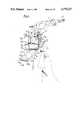
- FIG. 1is a perspective view of the first system
- FIG. 2is a front elevation of the system of FIG. 1;
- FIG. 3is a plan view of the system of FIG. 1;
- FIG. 4is a part-section on line IV--IV of FIG. 3;
- FIG. 5is a part-section on line V--V of FIG. 3;
- FIG. 6is a sectional view of components 35a and 43a of FIG. 4;
- FIG. 8is a pictorial representation of the optical elements of one half of a goggle of the system; optical elements.
- FIG. 9is an exploded diagrammatic view of part of the second system.
- FIG. 10is a front view of the second system and
- the first system to be describedcomprises a night vision goggle 11 secured to a helmet 13 by a mounting 15.
- the optical arrangements 17a, 17bare supported from and within a housing 20 which is attached to the mounting 15.
- the eyepieces 21a, 21bare separated in accordance with a prescribed interocular spacing.
- the mounting 15is a channel section member the flanges 23 of which taper from front to rear and are provided with bent-out lugs 25, the whole conforming substantially to the contours of the outer skin of the helmet 13 and being fixed to the helmet by screws 27 through the lugs 25.
- the housing 20is a light weight housing and defines three principal chambers 31a, 31b and 31c. Two of the chambers 31a, 31b, accommodate optical elements of the optical projectors 19a, 19b, respectively.
- the other chamber 31chouses power supplies for the optical projectors.
- each of the chambers 31a, 31bhouses an image intensifier 33a or 33b and a roof prism 35a or 35b, and each chamber has afront wall 37a or 37b into a threaded aperture in which a casing 41a or 41bis screwed which houses an objective lens 39a or 39b of the optical projector, 19a or 19b.
- Each roof prism 35a or 35bis secured to a bracket, as 43a (see FIG. 6).
- Each bracket as 43ahas a web portion, as 45a, which seats on abutments, as 47a, 49a or 47b, 49b in the relevant chamber 31a or 31b.
- the prisms 35a, 35bare isolated from their brackets by rubber mounts, as 50a in FIG.6.
- the brackets, as 43aare secured to their associated abutments, as 47a 49a, by screws 51.
- the roof prisms 35a, 35bare in the optical paths at the intersection of the optical axes of the objectives 39a, 39b, respectively, and the opticalaxes of the image intensifiers 33a, 33b, respectively, the optical axis of each objective and the optical axis of the associated image intensifer being perpindicular to one another.
- the third chamber 31cis central between the chambers 31a and 31b and, as already remarked, houses power supplies 51a, 51b in particular, for the image intensifiers 33a, 33b respectively.
- the power supplies 51a, 51bare connectable to a battery pack (not shown) by means of a lead 52 extending through the channel section mounting 15.
- the eyepieces 21a, 21bare collimating eyepieces.
- Each eyepieceas 21a in FIG. 4, comprises a two-part body of optically refractive material, such as glass or plastics material, within a frame 53secured to housing 20. Between the two parts 55, 57, or each eyepiece 21a or 21b there is a collimating spherical partially light-transmissive, partially light-reflective surface 54.
- the part 55 of each eyepiece 21a or21bhas an input face 59 and an output face 63.
- the input face 59lies in a plane generally parallel to the output face 61 of the image intensifier 33.
- the output face 63is planar and is inclined acutely with respect to the input face 59.
- each eyepiece 21a or 21bis in form generally complementary to the part 55.
- the part 57has a planar input surface 67 parallel to the output face 63 of the part 55.
- the optical axis of the mirror surface constituted by each interfaceis parallel to the optical axes of the objectives 39a, 39b.
- the goggleis displaceable (see FIG. 5) between operational and stowed positions A and B, respectively. Displacement is by pivotal movement of the housing 20 about a hinge axis between the housing and the mounting 15.
- the goggle 11is latched in each position, operational or stowed, by a detent arrangement comprising a ball ended stud 71 on a projection 73 of the housing 20 and a leaf spring 75 secured at one end to the mounting 15.
- the ball ended stud 71engages the leaf spring in one or the other of two apertures 77, 79 respectively, depending on the position at which the goggle 11 is to be held.
- each optical arrangement 17a, 17bOperation of each optical arrangement 17a, 17b is best understood by reference to FIG. 8 from which it may be seen that rays from a distant scene forward of an observer wearing the goggle, the same being represented for simplicity by a symbol F, are, after inversion by the objective 39 and folding and inversion by the roof prism 35, directed ontothe image intensifier 33 to form an intensified real image of the forward scene at the output face 61 of the intensifier. Rays from this intensifiedreal image then enter the eyepiece 21 via input face 59 undergoing refraction, are then totally reflected at the output face 63 of the eyepiece, tben reflected at the collimating spherical partially reflectivesurface 54 and are finally transmitted through the output face 63 to the observer.
- the parallelism between the face 67 and the face 63the distant scene may be simultaneously directed viewed by the observer, through the eyepiece 21, without distortion, superimposed on and in register with his view of the intensified image of the forward scene.
- the optical arrangements 17a, 17bare designed so that, in respect of points in a major part of the area of the real image at the output face 61, rays over a wide range of angles are refracted at the input face 59 and emerge from the output face 63.
- reflection at the output face 63occurs by reason of rays being incident at angles equal to or greater than the critical angle for the material of the eyepiece 21.
- one or more marginal portions of the output face 63may be provided with a fully reflective coating so as to reflect rays incident on such marginal portions of the face 63 at angles less thanthe critical angle.
- light entering the eyepiece 21 via input face 59may alternatively be reflected forwardlytowards surface 54 at an internal partially light-transmissive surface of the eyepiece 21 provided at the interface of two components parts of the eyepiece in similar manner to the spherical surface 54.
- the spherical reflective surface 54may be provided by a conventional partially light-transmissive partially light-reflective coating.
- the surface 54is provided by an optically tuned coating, such for example, as a multilayer coating or a holographic coating formed as described e.g. in U.K. Patent Specification No. 2,971,866.
- the light path to one of the eyepieces of the goggle 11, say eyepiece 21b,has a composite prism 36 to serve as a beam splitter.
- the prism 36comprises a roof prism 35b as hereinbefore described surmounted by a further prism element 35c, the surface of the prism element 35c at the interface being complementary to the roof surface of the roof prism 35b.
- a ray folding elementserves to deflect light from a display device in the form of a cathode ray tube (CRT) 42 to the composite prism 36 by way of the relay lens 38.
- the input face of the image intensifier 33blies in the focal plane of the relay lens 38 so that a real image cf the CRT display is formed at the output face of the intensifier.
- the CRT 42may constitute the final element of a subsystem which includes a remotely mounted infra-red or low light television sensor(not shown). Signals from the remote latter sensor are utilized in the control of bright up during CRT scanning thereby to form a visual representation of the real world forward scene at the CRT screen.
- aCRThas been referred to specifically, other image forming devices such as,for example as light emitting diode (LED) arrays may be employed.
- the gogglemay, for this purpose, be provided with a reticle 44 located in the light path to one of the eyepieces, say eyepiece 21b.
- the reticle 44may, as shown, be a graticule and an associated illumination source 48 disposed between the output face of the image intensifier 33b and the input face of the eyepiece 21b.
- the graticule showncomprises a disc of glass 46 etched withthe synthetic data, for example, a cross as shown or other director.
- the reticlemay comprise a group of optical fibres not shown each of which is illuminated at one end, for example, by a light emitting diode (LED), and has its other end disposed between the output face of the image intensifier 33b and the eyepiece 21b.
- LEDlight emitting diode
- Activation of the several LEDscreates at the remote ends of the corresponding optical fibres a pattern of bright spots constituting the synthetic data to be viewed through the eyepiece.
- Such synthetic visual dataappears superimposed on the view of the forward scene seen directly through the eyepiece 21b or the representation of the forward scene reflected to the user by the eyepiece 21b after amplification by the imageintensifier 33b.
- FIGS. 10 and 11The goggle of FIG. 9 is further illustrated in FIGS. 10 and 11 supported ona helmet where it will be seen that the cathode ray and associated HV powersupply are housed within a transversely projecting protective cover 48.
- the interocular spacing of the eyepiecesis adjustable by means of a centrally positioned adjustment screw and knurled wheel 82, the power supplies 83a,83b for the image intensifiers being housed to the left and right respectively of the optical projectors 19a, 19b.
- the eyepieces 21have been represented in the above described embodiments each as two parts 55 and 57 of optically refractive material with a partially light-transmissive, partially light-reflective surface, concavely curved at the interface 54 between the two parts, in the described embodiment, spherically, towards the output surface 63, for improved optical performance one or the other or both of the two parts maybe of composite construction, the or each composite part comprising two or more segments of different refractive index. By such an expedient chromatic aberration may be reduced or avoided altogether.
- the large eye reliefi.e. the space between the eyes and the eyepiecesenables the wearer to see around the eyepieces thereby permitting the wearer to view cockpit instruments and other parts of the real world scene; it also permits personal correcting spectacles to be worn.
- the goggleis small thereby allowing the pilot to eject wearing the helmet and goggle.
- Each image intensifierneed cover only relatively a small angle, 30° in the described embodiment. The resolution is accordingly improved.
- the aforedescribed goggleis not necessarily devoid of optical defects such for example as optical distortion, astigmatism and coma. Whilst means for mitigating such defects have not been specifically described it is, of course, possible to introduce into the optical system of a goggle optical elements in the form of prisms and/or lenses for the purpose of minimising such defects.
- the additional optical elementscan be located between the observer's viewing position and the surface 63 of the eyepiece 21a, 21b; or they can occupy a positionadjacent the input surface 59 of the eyepieces 21a, 21b or they can be present at both such places or at other points in the optical paths of thesystem.
Landscapes
- Physics & Mathematics (AREA)
- General Physics & Mathematics (AREA)
- Optics & Photonics (AREA)
- Astronomy & Astrophysics (AREA)
Abstract
Description
Claims (17)
Applications Claiming Priority (4)
| Application Number | Priority Date | Filing Date | Title |
|---|---|---|---|
| GB8131011 | 1981-10-14 | ||
| GB8131011 | 1981-10-14 | ||
| GB8211499 | 1982-04-21 | ||
| GB8211499 | 1982-04-21 |
Related Parent Applications (1)
| Application Number | Title | Priority Date | Filing Date |
|---|---|---|---|
| US06908375Continuation | 1986-09-17 |
Publications (1)
| Publication Number | Publication Date |
|---|---|
| US4775217Atrue US4775217A (en) | 1988-10-04 |
Family
ID=26280966
Family Applications (1)
| Application Number | Title | Priority Date | Filing Date |
|---|---|---|---|
| US07/028,904Expired - LifetimeUS4775217A (en) | 1981-10-14 | 1987-03-23 | Night vision viewing system |
Country Status (6)
| Country | Link |
|---|---|
| US (1) | US4775217A (en) |
| EP (1) | EP0077193B1 (en) |
| BR (1) | BR8205968A (en) |
| DE (1) | DE3266408D1 (en) |
| GB (1) | GB2108702B (en) |
| IL (1) | IL66972A0 (en) |
Cited By (128)
| Publication number | Priority date | Publication date | Assignee | Title |
|---|---|---|---|---|
| WO1989004008A1 (en)* | 1987-10-27 | 1989-05-05 | Night Vision General Partnership | Compact see-through night vision goggles |
| US4961626A (en)* | 1989-02-21 | 1990-10-09 | United Techologies Corporation | Direct incorporation of night vision in a helmet mounted display |
| US4968123A (en)* | 1989-04-24 | 1990-11-06 | United Technologies Corporation | Helmet mounted display configured for simulator use |
| US4969714A (en)* | 1989-02-21 | 1990-11-13 | United Technologies Corporation | Helmet mounted display having dual interchangeable optical eyepieces |
| US5084780A (en)* | 1989-09-12 | 1992-01-28 | Itt Corporation | Telescopic sight for day/night viewing |
| US5254852A (en)* | 1992-05-28 | 1993-10-19 | Night Vision General Partnership | Helmet-mounted night vision system and secondary imager |
| US5267061A (en)* | 1990-02-20 | 1993-11-30 | Hughes Aircraft Company | Non-interfering viewing systems for use in catadioptric projection systems |
| US5396069A (en)* | 1993-07-01 | 1995-03-07 | The United States Of America As Represented By The Secretary Of The Air Force | Portable monocular night vision apparatus |
| US5416315A (en)* | 1994-01-24 | 1995-05-16 | Night Vision General Partnership | Visor-mounted night vision visor |
| US5526022A (en)* | 1993-01-06 | 1996-06-11 | Virtual I/O, Inc. | Sourceless orientation sensor |
| US5619377A (en)* | 1992-02-07 | 1997-04-08 | Virtual I/O, Inc. | Optically corrected helmet mounted display |
| EP0790513A2 (en) | 1996-02-15 | 1997-08-20 | Canon Kabushiki Kaisha | Zoom lens |
| US5701202A (en)* | 1995-05-18 | 1997-12-23 | Olympus Optical Co., Ltd. | Head or face mounted image display apparatus |
| DE19625435A1 (en)* | 1996-06-25 | 1998-01-02 | Klaus Dr Ing Schlueter | Spectacles with information blended on to lenses |
| US5706136A (en)* | 1995-02-28 | 1998-01-06 | Canon Kabushiki Kaisha | Optical system, and image observing apparatus and image pickup apparatus using it |
| EP0788003A3 (en)* | 1996-01-29 | 1998-04-29 | Canon Kabushiki Kaisha | Phototaking optical system and optical device |
| US5864326A (en)* | 1992-02-07 | 1999-01-26 | I-O Display Systems Llc | Depixelated visual display |
| US5903396A (en)* | 1997-10-17 | 1999-05-11 | I/O Display Systems, Llc | Intensified visual display |
| US5903395A (en)* | 1994-08-31 | 1999-05-11 | I-O Display Systems Llc | Personal visual display system |
| US5923477A (en)* | 1994-02-07 | 1999-07-13 | Olympus Optical Co., Ltd. | Image display apparatus having a reflecting surface that bends light rays |
| US5973858A (en)* | 1996-01-29 | 1999-10-26 | Canon Kabushiki Kaisha | Reflecting optical system and optical apparatus |
| US5991087A (en)* | 1993-11-12 | 1999-11-23 | I-O Display System Llc | Non-orthogonal plate in a virtual reality or heads up display |
| US5991085A (en) | 1995-04-21 | 1999-11-23 | I-O Display Systems Llc | Head-mounted personal visual display apparatus with image generator and holder |
| US5995287A (en)* | 1995-09-27 | 1999-11-30 | Canon Kabushiki Kaisha | Optical element having a plurality of decentered reflecting curved surfaces, and optical instrument including the same |
| US5999311A (en)* | 1996-03-26 | 1999-12-07 | Canon Kabushiki Kaisha | Small-sized variable magnification optical system |
| US6021004A (en)* | 1995-02-28 | 2000-02-01 | Canon Kabushiki Kaisha | Reflecting type of zoom lens |
| EP0908750A3 (en)* | 1997-09-16 | 2000-02-23 | Canon Kabushiki Kaisha | Optical element and optical system having the same |
| US6034823A (en)* | 1997-02-07 | 2000-03-07 | Olympus Optical Co., Ltd. | Decentered prism optical system |
| US6075644A (en)* | 1996-12-20 | 2000-06-13 | Night Vision General Partnership | Panoramic night vision goggles |
| US6097543A (en)* | 1992-02-07 | 2000-08-01 | I-O Display Systems Llc | Personal visual display |
| US6097550A (en)* | 1997-02-12 | 2000-08-01 | Canon Kabushiki Kaisha | Optical system and image taking apparatus |
| US6120156A (en)* | 1997-10-16 | 2000-09-19 | Canon Kabushiki Kaisha | Optical element and optical system having the same |
| US6124986A (en)* | 1996-08-27 | 2000-09-26 | Canon Kabushiki Kaisha | Zoom optical system and image pickup apparatus |
| US6160666A (en)* | 1994-02-07 | 2000-12-12 | I-O Display Systems Llc | Personal visual display system |
| US6163400A (en)* | 1996-07-19 | 2000-12-19 | Canon Kabushiki Kaisha | Variable magnification optical system and image pickup apparatus using the same |
| US6166859A (en)* | 1998-08-05 | 2000-12-26 | Canon Kabushiki Kaisha | Viewfinder optical system and optical apparatus having the same |
| US6166866A (en)* | 1995-02-28 | 2000-12-26 | Canon Kabushiki Kaisha | Reflecting type optical system |
| US6191892B1 (en) | 1996-04-02 | 2001-02-20 | Canon Kabushiki Kaisha | Image display apparatus |
| US6195206B1 (en) | 1998-01-13 | 2001-02-27 | Elbit Systems Ltd. | Optical system for day and night use |
| US6252721B1 (en) | 1998-09-16 | 2001-06-26 | Canon Kabushiki Kaisha | Mold for molding optical element, mold structure for molding optical element, molding apparatus, optical element molded from resin material, and optical element constituted by plurality of optical surfaces |
| US6268963B1 (en) | 1997-08-22 | 2001-07-31 | Canon Kabushiki Kaisha | Optical system having a reflecting surface |
| US6278553B1 (en) | 1998-02-27 | 2001-08-21 | Canon Kabushiki Kaisha | Optical system having refractive index distribution |
| US6278554B1 (en) | 1998-10-30 | 2001-08-21 | Canon Kabushiki Kaisha | Image pickup optical system |
| US6301064B1 (en) | 1996-08-27 | 2001-10-09 | Canon Kabushiki Kaisha | Optical apparatus |
| US6304386B1 (en)* | 1997-06-20 | 2001-10-16 | Sextant Avionique | Display device for helmet-mounted display |
| US6310728B1 (en) | 1998-06-19 | 2001-10-30 | Canon Kabushiki Kaisha | Image viewing apparatus |
| US6351338B2 (en) | 1998-02-26 | 2002-02-26 | Canon Kabushiki Kaisha | Image pickup optical system |
| US6379009B1 (en) | 1996-04-24 | 2002-04-30 | James L. Fergason | Conjugate optics projection display with image enhancement |
| JP3292174B2 (en) | 1999-05-11 | 2002-06-17 | キヤノン株式会社 | Optical system and imaging apparatus using the same |
| JP3291974B2 (en) | 1995-04-24 | 2002-06-17 | キヤノン株式会社 | Zoom optical system and imaging apparatus including the same |
| JP3292173B2 (en) | 1999-05-11 | 2002-06-17 | キヤノン株式会社 | Optical element and imaging device having the same |
| JP3291975B2 (en) | 1995-04-24 | 2002-06-17 | キヤノン株式会社 | Zoom optical system and imaging apparatus using the same |
| US6426841B1 (en) | 1997-08-27 | 2002-07-30 | Canon Kabushiki Kaisha | Optical apparatus |
| JP3320252B2 (en) | 1995-04-24 | 2002-09-03 | キヤノン株式会社 | Reflection type optical system and imaging apparatus using the same |
| JP3332890B2 (en) | 1999-05-11 | 2002-10-07 | キヤノン株式会社 | Optical element and imaging device having the same |
| US6490095B2 (en) | 2000-03-23 | 2002-12-03 | Canon Kabushiki Kaisha | Image display apparatus |
| US6549332B2 (en) | 1996-02-15 | 2003-04-15 | Canon Kabushiki Kaisha | Reflecting optical system |
| US6552854B2 (en) | 2000-04-28 | 2003-04-22 | Canon Kabushiki Kaisha | Image display apparatus and optical system |
| US6556360B2 (en) | 1998-12-30 | 2003-04-29 | Canon Kabushiki Kaisha | Optical element and optical device having it |
| US20030107816A1 (en)* | 2001-11-14 | 2003-06-12 | Akinari Takagi | Display optical system, image display apparatus, image taking optical system, and image taking apparatus |
| US6590713B2 (en) | 2000-10-26 | 2003-07-08 | Canon Kabushiki Kaisha | Image observation apparatus and image observation system |
| US6594085B2 (en) | 2000-04-28 | 2003-07-15 | Canon Kabushiki Kaisha | Image display apparatus and optical system |
| US20030156327A1 (en)* | 2002-02-15 | 2003-08-21 | Yukari Terakawa | Optical element and optical device using the same |
| US6616287B2 (en) | 1997-12-02 | 2003-09-09 | Canon Kabushiki Kaisha | Optical element |
| WO2003081320A1 (en)* | 2002-03-21 | 2003-10-02 | Lumus Ltd. | Light guide optical device |
| US6636360B1 (en) | 1995-02-28 | 2003-10-21 | Canon Kabushiki Kaisha | Reflecting type of zoom lens |
| US20030197943A1 (en)* | 2001-11-14 | 2003-10-23 | Shoichi Yamazaki | Optical system, image display apparatus, and image taking apparatus |
| US6637899B2 (en) | 1998-09-25 | 2003-10-28 | Canon Kabushiki Kaisha | Optical element and optical system having the same |
| US6814442B2 (en) | 2000-04-28 | 2004-11-09 | Canon Kabushiki Kaisha | Image display apparatus and optical system |
| US7253960B2 (en) | 1994-06-13 | 2007-08-07 | Canon Kabushiki Kaisha | Head-up display device with rotationally asymmetric curved surface |
| US7599561B2 (en) | 2006-02-28 | 2009-10-06 | Microsoft Corporation | Compact interactive tabletop with projection-vision |
| US20090284832A1 (en)* | 2008-05-16 | 2009-11-19 | Day & Night Display Systems, Llc | Night vision glasses |
| US20100103267A1 (en)* | 2008-10-27 | 2010-04-29 | O'rourke Brian | Night vision system |
| US20100128135A1 (en)* | 2000-09-15 | 2010-05-27 | Night Vision Corporation | Modular night vision goggles with pellicle |
| US20100177201A1 (en)* | 2000-09-15 | 2010-07-15 | Night Vision Corporation | Expandable night vision goggles |
| US20100315720A1 (en)* | 2008-03-13 | 2010-12-16 | Day And Night Displays Systems, Llc | Visor heads-up display |
| US20130155244A1 (en)* | 2008-10-27 | 2013-06-20 | Brian O'Rourke | Night vision system |
| US8611667B2 (en) | 2006-02-28 | 2013-12-17 | Microsoft Corporation | Compact interactive tabletop with projection-vision |
| DE102015116402A1 (en) | 2015-09-28 | 2017-03-30 | Carl Zeiss Smart Optics Gmbh | Optical component and method for its production |
| US9729767B2 (en) | 2013-03-22 | 2017-08-08 | Seiko Epson Corporation | Infrared video display eyewear |
| US10026177B2 (en) | 2006-02-28 | 2018-07-17 | Microsoft Technology Licensing, Llc | Compact interactive tabletop with projection-vision |
| US10073264B2 (en) | 2007-08-03 | 2018-09-11 | Lumus Ltd. | Substrate-guide optical device |
| US10133070B2 (en) | 2016-10-09 | 2018-11-20 | Lumus Ltd. | Aperture multiplier using a rectangular waveguide |
| US10261321B2 (en) | 2005-11-08 | 2019-04-16 | Lumus Ltd. | Polarizing optical system |
| US10302835B2 (en) | 2017-02-22 | 2019-05-28 | Lumus Ltd. | Light guide optical assembly |
| US10437031B2 (en) | 2016-11-08 | 2019-10-08 | Lumus Ltd. | Light-guide device with optical cutoff edge and corresponding production methods |
| US10481319B2 (en) | 2017-03-22 | 2019-11-19 | Lumus Ltd. | Overlapping facets |
| US10488660B2 (en) | 2008-03-13 | 2019-11-26 | Everysight Ltd. | Wearable optical display system for unobstructed viewing |
| US10506220B2 (en) | 2018-01-02 | 2019-12-10 | Lumus Ltd. | Augmented reality displays with active alignment and corresponding methods |
| US10520732B2 (en) | 2012-05-21 | 2019-12-31 | Lumus Ltd. | Head-mounted display eyeball tracker integrated system |
| US10520731B2 (en) | 2014-11-11 | 2019-12-31 | Lumus Ltd. | Compact head-mounted display system protected by a hyperfine structure |
| US10551544B2 (en) | 2018-01-21 | 2020-02-04 | Lumus Ltd. | Light-guide optical element with multiple-axis internal aperture expansion |
| US10732415B2 (en) | 2005-02-10 | 2020-08-04 | Lumus Ltd. | Substrate-guide optical device |
| US10809528B2 (en) | 2014-04-23 | 2020-10-20 | Lumus Ltd. | Compact head-mounted display system |
| US10845604B2 (en) | 2012-09-26 | 2020-11-24 | Sony Corporation | Mounting apparatus for head-mounted display |
| US10895679B2 (en) | 2017-04-06 | 2021-01-19 | Lumus Ltd. | Light-guide optical element and method of its manufacture |
| US11243434B2 (en) | 2017-07-19 | 2022-02-08 | Lumus Ltd. | LCOS illumination via LOE |
| US11256094B2 (en) | 2008-03-13 | 2022-02-22 | Everysight Ltd. | Wearable optical display system for unobstructed viewing |
| US11262587B2 (en) | 2018-05-22 | 2022-03-01 | Lumus Ltd. | Optical system and method for improvement of light field uniformity |
| US20220197006A1 (en)* | 2020-12-23 | 2022-06-23 | Brian Reynolds | Wearable, adjustable, hands-free binocular device |
| US11415812B2 (en) | 2018-06-26 | 2022-08-16 | Lumus Ltd. | Compact collimating optical device and system |
| US11448816B2 (en) | 2019-01-24 | 2022-09-20 | Lumus Ltd. | Optical systems including light-guide optical elements with two-dimensional expansion |
| US11500143B2 (en) | 2017-01-28 | 2022-11-15 | Lumus Ltd. | Augmented reality imaging system |
| US11513349B2 (en) | 2008-03-13 | 2022-11-29 | Everysight Ltd. | Optical see-through (OST) near-eye display (NED) system integrating ophthalmic correction |
| US11523092B2 (en) | 2019-12-08 | 2022-12-06 | Lumus Ltd. | Optical systems with compact image projector |
| US11526003B2 (en) | 2018-05-23 | 2022-12-13 | Lumus Ltd. | Optical system including light-guide optical element with partially-reflective internal surfaces |
| US11543583B2 (en) | 2018-09-09 | 2023-01-03 | Lumus Ltd. | Optical systems including light-guide optical elements with two-dimensional expansion |
| US11561335B2 (en) | 2019-12-05 | 2023-01-24 | Lumus Ltd. | Light-guide optical element employing complementary coated partial reflectors, and light-guide optical element having reduced light scattering |
| US11567323B2 (en)* | 2019-12-01 | 2023-01-31 | Vision Products, Llc | Partial electronic see-through head-mounted display |
| US11630260B2 (en) | 2020-05-24 | 2023-04-18 | Lumus Ltd. | Production method and corresponding structures of compound light-guide optical elements |
| US11644676B2 (en) | 2020-09-11 | 2023-05-09 | Lumus Ltd. | Image projector coupled to a light guide optical element |
| US11789264B2 (en) | 2021-07-04 | 2023-10-17 | Lumus Ltd. | Display with stacked light-guide elements providing different parts of field of view |
| US11796729B2 (en) | 2021-02-25 | 2023-10-24 | Lumus Ltd. | Optical aperture multipliers having a rectangular waveguide |
| US11822088B2 (en) | 2021-05-19 | 2023-11-21 | Lumus Ltd. | Active optical engine |
| US11849262B2 (en) | 2019-03-12 | 2023-12-19 | Lumus Ltd. | Image projector |
| US11860369B2 (en) | 2021-03-01 | 2024-01-02 | Lumus Ltd. | Optical system with compact coupling from a projector into a waveguide |
| US11886008B2 (en) | 2021-08-23 | 2024-01-30 | Lumus Ltd. | Methods of fabrication of compound light-guide optical elements having embedded coupling-in reflectors |
| US11885966B2 (en) | 2019-12-30 | 2024-01-30 | Lumus Ltd. | Optical systems including light-guide optical elements with two-dimensional expansion |
| US11914161B2 (en) | 2019-06-27 | 2024-02-27 | Lumus Ltd. | Apparatus and methods for eye tracking based on eye imaging via light-guide optical element |
| US11914187B2 (en) | 2019-07-04 | 2024-02-27 | Lumus Ltd. | Image waveguide with symmetric beam multiplication |
| US12124037B2 (en) | 2020-05-24 | 2024-10-22 | Lumus Ltd. | Compound light-guide optical elements |
| US12124050B2 (en) | 2019-02-28 | 2024-10-22 | Lumus Ltd. | Compact collimated image projector |
| US12135445B2 (en) | 2019-04-15 | 2024-11-05 | Lumus Ltd. | Method of fabricating a light-guide optical element |
| US12140790B2 (en) | 2019-07-18 | 2024-11-12 | Lumus Ltd. | Encapsulated light-guide optical element |
| US12210157B2 (en) | 2019-04-04 | 2025-01-28 | Lumus Ltd. | Air-gap free perpendicular near-eye display |
| US12222508B2 (en) | 2020-08-26 | 2025-02-11 | Lumus Ltd. | Generation of color images using white light as source |
| US12320983B1 (en) | 2022-08-18 | 2025-06-03 | Lumus Ltd. | Image projector with polarizing catadioptric collimator |
| US12436400B2 (en) | 2020-08-23 | 2025-10-07 | Lumus Ltd. | Optical system |
Families Citing this family (30)
| Publication number | Priority date | Publication date | Assignee | Title |
|---|---|---|---|---|
| FR2542459B1 (en)* | 1983-03-07 | 1987-01-30 | Thomson Csf | HIGH HEAD SIGHT |
| GB8320945D0 (en)* | 1983-08-03 | 1983-09-07 | Marconi Avionics | Night vision goggles |
| JPS6138504A (en)* | 1984-07-30 | 1986-02-24 | バルナウルスコエ オピトノ−コンストルクトルスコエ ビユ−ロ アフトマチキ ナウチノ−プロイズヴオドストヴエンノゴ オビエデイネニア“ヒマクトマチカ” | Measuring device for wire diameter |
| FR2593932B1 (en)* | 1986-02-04 | 1989-12-01 | Thomson Csf | LARGE FIELD VISUALIZATION DEVICE WITH HIGH OPTICAL EFFICIENCY |
| GB8622378D0 (en)* | 1986-09-17 | 1987-01-14 | Gec Avionics | Helmet systems |
| US6008779A (en)* | 1987-03-24 | 1999-12-28 | Gec-Marconi Limited | Night vision viewing systems |
| FR2613497B1 (en)* | 1987-03-31 | 1991-08-16 | Thomson Csf | BINOCULAR, HOLOGRAPHIC AND LARGE FIELD SIGHT, USED ON HELMET |
| GB8714203D0 (en)* | 1987-06-17 | 1987-11-18 | Gec Avionics | Gun sights |
| US4859030A (en)* | 1987-07-29 | 1989-08-22 | Honeywell, Inc. | Helmet mounted display with improved brightness |
| EP0365406B1 (en)* | 1988-10-21 | 1993-09-29 | Thomson-Csf | Optical collimating system for a helmet visual |
| GB8825204D0 (en)* | 1988-10-27 | 1989-04-19 | Marconi Gec Ltd | Helmet systems |
| FR2648573B1 (en)* | 1989-06-14 | 1991-08-30 | Thomson Csf | VISUALIZATION DEVICE FOR A VIEW OF AN ERGONOMIC HELMET WITH A LARGE FIELD OF OBSERVATION |
| EP0488987B1 (en)* | 1990-11-26 | 1996-01-31 | Michael Dr. Truppe | Method for representing moving bodies |
| US5823958A (en)* | 1990-11-26 | 1998-10-20 | Truppe; Michael | System and method for displaying a structural data image in real-time correlation with moveable body |
| US5880773A (en)* | 1991-12-27 | 1999-03-09 | Sony Corporation | Head mounted display configured to a user's physical features |
| GB9217058D0 (en)* | 1992-08-12 | 1992-11-04 | Marconi Gec Ltd | Display system |
| JP3163786B2 (en) | 1992-10-09 | 2001-05-08 | ソニー株式会社 | Glasses-type image display device |
| IL103900A (en)* | 1992-11-26 | 1998-06-15 | Electro Optics Ind Ltd | Optical system |
| JPH06331928A (en)* | 1993-05-24 | 1994-12-02 | Sony Corp | Spectacles type display device |
| US5543816A (en)* | 1993-10-07 | 1996-08-06 | Virtual Vision | Head mounted display system with aspheric optics |
| NL9401110A (en)* | 1994-07-01 | 1996-02-01 | Optische Ind Oede Oude Delftoe | Display system designed to superimpose three images to obtain a mixed image. |
| NL9401109A (en)* | 1994-07-01 | 1996-02-01 | Optische Ind Oede Oude Delftoe | Display system intended for mounting on the head or on a helmet and a helmet provided with such a display system. |
| US5748264A (en)* | 1995-01-10 | 1998-05-05 | Hughes Electronics | Distortion Corrected display |
| WO1996036898A2 (en)* | 1995-05-15 | 1996-11-21 | He Holdings, Inc., Doing Business As Hughes Electronics | Low-cost light-weight head-mounted virtual-image projection display with low moments of inertia and low center of gravity |
| WO1997009652A1 (en)* | 1995-09-06 | 1997-03-13 | B.V. Optische Industrie 'de Oude Delft' | Display system intended to be attached to the head or to a helmet, and a helmet provided with such a display system |
| WO2000014585A1 (en)* | 1998-09-02 | 2000-03-16 | Cairns And Brother Inc | Display system |
| JP4341108B2 (en)* | 1999-07-14 | 2009-10-07 | ソニー株式会社 | Virtual image observation optical device |
| EP2376971B1 (en) | 2008-12-12 | 2019-02-20 | BAE Systems PLC | Improvements in or relating to waveguides |
| EP2196842A1 (en)* | 2008-12-12 | 2010-06-16 | BAE Systems PLC | Improvements in or relating to waveguides |
| DE102014007283A1 (en)* | 2014-05-20 | 2015-11-26 | Clarigon Electronics Gmbh Austria | Night vision device |
Citations (3)
| Publication number | Priority date | Publication date | Assignee | Title |
|---|---|---|---|---|
| US3923370A (en)* | 1974-10-15 | 1975-12-02 | Honeywell Inc | Head mounted displays |
| US4361384A (en)* | 1980-06-27 | 1982-11-30 | The United States Of America As Represented By The Secretary Of The Army | High luminance miniature display |
| US4563061A (en)* | 1983-08-03 | 1986-01-07 | Marconi Avionics Limited | Night vision viewing systems |
Family Cites Families (5)
| Publication number | Priority date | Publication date | Assignee | Title |
|---|---|---|---|---|
| GB1264343A (en)* | 1968-08-12 | 1972-02-23 | ||
| GB1433333A (en)* | 1972-05-17 | 1976-04-28 | Fidelity Instr Co Ltd | Optical viewing devices |
| CH566562A5 (en)* | 1973-04-06 | 1975-09-15 | Weiss Helmut | |
| US4000419A (en)* | 1975-09-26 | 1976-12-28 | The United States Of America As Represented By The Secretary Of The Army | Apparatus for adding electronic display information to a night vision goggle display |
| IL55547A (en)* | 1977-10-17 | 1981-03-31 | Hughes Aircraft Co | Holographic one-tube goggle |
- 1982
- 1982-10-08DEDE8282305370Tpatent/DE3266408D1/ennot_activeExpired
- 1982-10-08GBGB08228835Apatent/GB2108702B/ennot_activeExpired
- 1982-10-08EPEP82305370Apatent/EP0077193B1/ennot_activeExpired
- 1982-10-12ILIL66972Apatent/IL66972A0/ennot_activeIP Right Cessation
- 1982-10-13BRBR8205968Apatent/BR8205968A/enunknown
- 1987
- 1987-03-23USUS07/028,904patent/US4775217A/ennot_activeExpired - Lifetime
Patent Citations (3)
| Publication number | Priority date | Publication date | Assignee | Title |
|---|---|---|---|---|
| US3923370A (en)* | 1974-10-15 | 1975-12-02 | Honeywell Inc | Head mounted displays |
| US4361384A (en)* | 1980-06-27 | 1982-11-30 | The United States Of America As Represented By The Secretary Of The Army | High luminance miniature display |
| US4563061A (en)* | 1983-08-03 | 1986-01-07 | Marconi Avionics Limited | Night vision viewing systems |
Cited By (204)
| Publication number | Priority date | Publication date | Assignee | Title |
|---|---|---|---|---|
| US5079416A (en)* | 1987-10-27 | 1992-01-07 | Night Vision General Partnership | Compact see-through night vision goggles |
| WO1989004008A1 (en)* | 1987-10-27 | 1989-05-05 | Night Vision General Partnership | Compact see-through night vision goggles |
| US4961626A (en)* | 1989-02-21 | 1990-10-09 | United Techologies Corporation | Direct incorporation of night vision in a helmet mounted display |
| US4969714A (en)* | 1989-02-21 | 1990-11-13 | United Technologies Corporation | Helmet mounted display having dual interchangeable optical eyepieces |
| US4968123A (en)* | 1989-04-24 | 1990-11-06 | United Technologies Corporation | Helmet mounted display configured for simulator use |
| US5084780A (en)* | 1989-09-12 | 1992-01-28 | Itt Corporation | Telescopic sight for day/night viewing |
| US5267061A (en)* | 1990-02-20 | 1993-11-30 | Hughes Aircraft Company | Non-interfering viewing systems for use in catadioptric projection systems |
| US5642227A (en)* | 1992-02-07 | 1997-06-24 | Virtual I/O, Inc. | Optical correction for virtual reality and heads up displays |
| US5619377A (en)* | 1992-02-07 | 1997-04-08 | Virtual I/O, Inc. | Optically corrected helmet mounted display |
| US6097543A (en)* | 1992-02-07 | 2000-08-01 | I-O Display Systems Llc | Personal visual display |
| US5949583A (en)* | 1992-02-07 | 1999-09-07 | I-O Display Systems Llc | Head-mounted display with image generator, fold mirror and mirror for transmission to the eye position of the user |
| US5864326A (en)* | 1992-02-07 | 1999-01-26 | I-O Display Systems Llc | Depixelated visual display |
| US5254852A (en)* | 1992-05-28 | 1993-10-19 | Night Vision General Partnership | Helmet-mounted night vision system and secondary imager |
| US5526022A (en)* | 1993-01-06 | 1996-06-11 | Virtual I/O, Inc. | Sourceless orientation sensor |
| US5396069A (en)* | 1993-07-01 | 1995-03-07 | The United States Of America As Represented By The Secretary Of The Air Force | Portable monocular night vision apparatus |
| US5991087A (en)* | 1993-11-12 | 1999-11-23 | I-O Display System Llc | Non-orthogonal plate in a virtual reality or heads up display |
| US5416315A (en)* | 1994-01-24 | 1995-05-16 | Night Vision General Partnership | Visor-mounted night vision visor |
| US5923477A (en)* | 1994-02-07 | 1999-07-13 | Olympus Optical Co., Ltd. | Image display apparatus having a reflecting surface that bends light rays |
| US6160666A (en)* | 1994-02-07 | 2000-12-12 | I-O Display Systems Llc | Personal visual display system |
| US7538950B2 (en) | 1994-06-13 | 2009-05-26 | Canon Kabushiki Kaisha | Display device |
| US7495836B2 (en) | 1994-06-13 | 2009-02-24 | Canon Kabushiki Kaisha | Display device |
| US7262919B1 (en) | 1994-06-13 | 2007-08-28 | Canon Kabushiki Kaisha | Head-up display device with curved optical surface having total reflection |
| US7505207B2 (en) | 1994-06-13 | 2009-03-17 | Canon Kabushiki Kaisha | Display device |
| US7253960B2 (en) | 1994-06-13 | 2007-08-07 | Canon Kabushiki Kaisha | Head-up display device with rotationally asymmetric curved surface |
| US20080055735A1 (en)* | 1994-06-13 | 2008-03-06 | Canon Kabushiki Kaisha | Display device |
| US7355795B1 (en) | 1994-06-13 | 2008-04-08 | Canon Kabushiki Kaisha | Head-up display device with curved optical surface having total reflection |
| US20080094719A1 (en)* | 1994-06-13 | 2008-04-24 | Canon Kabushiki Kaisha | Display device |
| US7567385B2 (en) | 1994-06-13 | 2009-07-28 | Canon Kabushiki Kaisha | Head-up display device with curved optical surface having total reflection |
| US5903395A (en)* | 1994-08-31 | 1999-05-11 | I-O Display Systems Llc | Personal visual display system |
| US20020105734A1 (en)* | 1995-02-28 | 2002-08-08 | Kenichi Kimura | Reflecting type optical system |
| US6021004A (en)* | 1995-02-28 | 2000-02-01 | Canon Kabushiki Kaisha | Reflecting type of zoom lens |
| US6785060B2 (en) | 1995-02-28 | 2004-08-31 | Canon Kabushiki Kaisha | Reflecting type optical system |
| US6639729B2 (en) | 1995-02-28 | 2003-10-28 | Canon Kabushiki Kaisha | Reflecting type of zoom lens |
| US6366411B1 (en) | 1995-02-28 | 2002-04-02 | Canon Kabushiki Kaisha | Reflecting type optical system |
| US6166866A (en)* | 1995-02-28 | 2000-12-26 | Canon Kabushiki Kaisha | Reflecting type optical system |
| US5706136A (en)* | 1995-02-28 | 1998-01-06 | Canon Kabushiki Kaisha | Optical system, and image observing apparatus and image pickup apparatus using it |
| US6636360B1 (en) | 1995-02-28 | 2003-10-21 | Canon Kabushiki Kaisha | Reflecting type of zoom lens |
| US6292309B1 (en) | 1995-02-28 | 2001-09-18 | Canon Kabushiki Kaisha | Reflecting type of zoom lens |
| US5991085A (en) | 1995-04-21 | 1999-11-23 | I-O Display Systems Llc | Head-mounted personal visual display apparatus with image generator and holder |
| JP3291975B2 (en) | 1995-04-24 | 2002-06-17 | キヤノン株式会社 | Zoom optical system and imaging apparatus using the same |
| JP3291974B2 (en) | 1995-04-24 | 2002-06-17 | キヤノン株式会社 | Zoom optical system and imaging apparatus including the same |
| JP3320252B2 (en) | 1995-04-24 | 2002-09-03 | キヤノン株式会社 | Reflection type optical system and imaging apparatus using the same |
| US6018423A (en)* | 1995-05-18 | 2000-01-25 | Olympus Optical Co., Ltd. | Optical system and optical apparatus |
| US5875056A (en)* | 1995-05-18 | 1999-02-23 | Olympus Optical Co., Ltd. | Head or face mounted image display apparatus |
| US5701202A (en)* | 1995-05-18 | 1997-12-23 | Olympus Optical Co., Ltd. | Head or face mounted image display apparatus |
| US6195207B1 (en) | 1995-05-18 | 2001-02-27 | Olympus Optical Co., Ltd. | Head or face mounted image display apparatus |
| US6317267B1 (en) | 1995-05-18 | 2001-11-13 | Olympus Optical Co., Ltd. | Head or face mounted image display apparatus |
| US6181470B1 (en) | 1995-09-27 | 2001-01-30 | Canon Kabushiki Kaisha | Optical element having a plurality of decentered reflecting curved surfaces, and optical instrument including the same |
| US5995287A (en)* | 1995-09-27 | 1999-11-30 | Canon Kabushiki Kaisha | Optical element having a plurality of decentered reflecting curved surfaces, and optical instrument including the same |
| EP0788003A3 (en)* | 1996-01-29 | 1998-04-29 | Canon Kabushiki Kaisha | Phototaking optical system and optical device |
| US5973858A (en)* | 1996-01-29 | 1999-10-26 | Canon Kabushiki Kaisha | Reflecting optical system and optical apparatus |
| US5917662A (en)* | 1996-01-29 | 1999-06-29 | Canon Kabushiki Kaisha | Phototaking optical system and optical device |
| US6728044B2 (en) | 1996-02-15 | 2004-04-27 | Canon Kabushiki Kaisha | Zoom lens |
| US6549332B2 (en) | 1996-02-15 | 2003-04-15 | Canon Kabushiki Kaisha | Reflecting optical system |
| US6522475B2 (en) | 1996-02-15 | 2003-02-18 | Canon Kabushiki Kaisha | Zoom lens |
| EP0790513A2 (en) | 1996-02-15 | 1997-08-20 | Canon Kabushiki Kaisha | Zoom lens |
| US6313942B1 (en) | 1996-03-26 | 2001-11-06 | Canon Kabushiki Kaisha | Small-sized variable magnification optical system |
| US5999311A (en)* | 1996-03-26 | 1999-12-07 | Canon Kabushiki Kaisha | Small-sized variable magnification optical system |
| US6459530B2 (en) | 1996-03-26 | 2002-10-01 | Canon Kabushiki Kaisha | Small-sized variable magnification optical system |
| US6191892B1 (en) | 1996-04-02 | 2001-02-20 | Canon Kabushiki Kaisha | Image display apparatus |
| US6379009B1 (en) | 1996-04-24 | 2002-04-30 | James L. Fergason | Conjugate optics projection display with image enhancement |
| DE19625435A1 (en)* | 1996-06-25 | 1998-01-02 | Klaus Dr Ing Schlueter | Spectacles with information blended on to lenses |
| US6163400A (en)* | 1996-07-19 | 2000-12-19 | Canon Kabushiki Kaisha | Variable magnification optical system and image pickup apparatus using the same |
| US6301064B1 (en) | 1996-08-27 | 2001-10-09 | Canon Kabushiki Kaisha | Optical apparatus |
| US6124986A (en)* | 1996-08-27 | 2000-09-26 | Canon Kabushiki Kaisha | Zoom optical system and image pickup apparatus |
| US6075644A (en)* | 1996-12-20 | 2000-06-13 | Night Vision General Partnership | Panoramic night vision goggles |
| US6034823A (en)* | 1997-02-07 | 2000-03-07 | Olympus Optical Co., Ltd. | Decentered prism optical system |
| US6097550A (en)* | 1997-02-12 | 2000-08-01 | Canon Kabushiki Kaisha | Optical system and image taking apparatus |
| US6304386B1 (en)* | 1997-06-20 | 2001-10-16 | Sextant Avionique | Display device for helmet-mounted display |
| US6268963B1 (en) | 1997-08-22 | 2001-07-31 | Canon Kabushiki Kaisha | Optical system having a reflecting surface |
| US6426841B1 (en) | 1997-08-27 | 2002-07-30 | Canon Kabushiki Kaisha | Optical apparatus |
| EP0908750A3 (en)* | 1997-09-16 | 2000-02-23 | Canon Kabushiki Kaisha | Optical element and optical system having the same |
| US6351333B2 (en) | 1997-09-16 | 2002-02-26 | Canon Kabushiki Kaisha | Optical element and optical system having the same |
| US6120156A (en)* | 1997-10-16 | 2000-09-19 | Canon Kabushiki Kaisha | Optical element and optical system having the same |
| US5903396A (en)* | 1997-10-17 | 1999-05-11 | I/O Display Systems, Llc | Intensified visual display |
| US6616287B2 (en) | 1997-12-02 | 2003-09-09 | Canon Kabushiki Kaisha | Optical element |
| US6195206B1 (en) | 1998-01-13 | 2001-02-27 | Elbit Systems Ltd. | Optical system for day and night use |
| US6351338B2 (en) | 1998-02-26 | 2002-02-26 | Canon Kabushiki Kaisha | Image pickup optical system |
| US6278553B1 (en) | 1998-02-27 | 2001-08-21 | Canon Kabushiki Kaisha | Optical system having refractive index distribution |
| US6310728B1 (en) | 1998-06-19 | 2001-10-30 | Canon Kabushiki Kaisha | Image viewing apparatus |
| US6166859A (en)* | 1998-08-05 | 2000-12-26 | Canon Kabushiki Kaisha | Viewfinder optical system and optical apparatus having the same |
| US6252721B1 (en) | 1998-09-16 | 2001-06-26 | Canon Kabushiki Kaisha | Mold for molding optical element, mold structure for molding optical element, molding apparatus, optical element molded from resin material, and optical element constituted by plurality of optical surfaces |
| US6637899B2 (en) | 1998-09-25 | 2003-10-28 | Canon Kabushiki Kaisha | Optical element and optical system having the same |
| US6278554B1 (en) | 1998-10-30 | 2001-08-21 | Canon Kabushiki Kaisha | Image pickup optical system |
| US6556360B2 (en) | 1998-12-30 | 2003-04-29 | Canon Kabushiki Kaisha | Optical element and optical device having it |
| JP3292174B2 (en) | 1999-05-11 | 2002-06-17 | キヤノン株式会社 | Optical system and imaging apparatus using the same |
| JP3332890B2 (en) | 1999-05-11 | 2002-10-07 | キヤノン株式会社 | Optical element and imaging device having the same |
| JP3292173B2 (en) | 1999-05-11 | 2002-06-17 | キヤノン株式会社 | Optical element and imaging device having the same |
| US6490095B2 (en) | 2000-03-23 | 2002-12-03 | Canon Kabushiki Kaisha | Image display apparatus |
| US6814442B2 (en) | 2000-04-28 | 2004-11-09 | Canon Kabushiki Kaisha | Image display apparatus and optical system |
| US6552854B2 (en) | 2000-04-28 | 2003-04-22 | Canon Kabushiki Kaisha | Image display apparatus and optical system |
| US6594085B2 (en) | 2000-04-28 | 2003-07-15 | Canon Kabushiki Kaisha | Image display apparatus and optical system |
| US7800043B2 (en) | 2000-09-15 | 2010-09-21 | Night Vision Corporation | Night vision goggles with detachable or reattachable modular components |
| US20100177201A1 (en)* | 2000-09-15 | 2010-07-15 | Night Vision Corporation | Expandable night vision goggles |
| US20100128135A1 (en)* | 2000-09-15 | 2010-05-27 | Night Vision Corporation | Modular night vision goggles with pellicle |
| US8269159B2 (en) | 2000-09-15 | 2012-09-18 | Night Vision Corporation | Modular panoramic night vision goggles having configurable attachments |
| US8431881B2 (en) | 2000-09-15 | 2013-04-30 | Kollsman, Inc. | Night vision goggles with pellicle |
| US6590713B2 (en) | 2000-10-26 | 2003-07-08 | Canon Kabushiki Kaisha | Image observation apparatus and image observation system |
| US20060126188A1 (en)* | 2001-11-14 | 2006-06-15 | Akinari Takagi | Display optical system, image display apparatus, imae taking optical system, and image taking apparatus |
| US7019909B2 (en) | 2001-11-14 | 2006-03-28 | Canon Kabushiki Kaisha | Optical system, image display apparatus, and image taking apparatus |
| US7012756B2 (en) | 2001-11-14 | 2006-03-14 | Canon Kabushiki Kaisha | Display optical system, image display apparatus, image taking optical system, and image taking apparatus |
| US20030107816A1 (en)* | 2001-11-14 | 2003-06-12 | Akinari Takagi | Display optical system, image display apparatus, image taking optical system, and image taking apparatus |
| US20030197943A1 (en)* | 2001-11-14 | 2003-10-23 | Shoichi Yamazaki | Optical system, image display apparatus, and image taking apparatus |
| US7446943B2 (en) | 2001-11-14 | 2008-11-04 | Canon Kabushiki Kaisha | Display optical system, image display apparatus, image taking optical system, and image taking apparatus |
| US6957006B2 (en)* | 2002-02-15 | 2005-10-18 | Omron Corporation | Optical element and optical device using the same |
| US20030156327A1 (en)* | 2002-02-15 | 2003-08-21 | Yukari Terakawa | Optical element and optical device using the same |
| US20080158685A1 (en)* | 2002-03-21 | 2008-07-03 | Yaakov Amitai | Light guide optical device |
| US20090097127A1 (en)* | 2002-03-21 | 2009-04-16 | Lumus Ltd. | Light guide optical device |
| US20090052046A1 (en)* | 2002-03-21 | 2009-02-26 | Lumus Ltd. | Light guide optical device |
| US7457040B2 (en) | 2002-03-21 | 2008-11-25 | Lumus Ltd. | Light guide optical device |
| US7576916B2 (en) | 2002-03-21 | 2009-08-18 | Lumus Ltd. | Light guide optical device |
| EP3260907A1 (en)* | 2002-03-21 | 2017-12-27 | Lumus Ltd | Light guide optical device |
| WO2003081320A1 (en)* | 2002-03-21 | 2003-10-02 | Lumus Ltd. | Light guide optical device |
| US20050180687A1 (en)* | 2002-03-21 | 2005-08-18 | Yaakov Amitai | Light guide optical device |
| CN101013178B (en)* | 2002-03-21 | 2012-09-05 | 鲁姆斯有限公司 | Light guide optical device |
| US7724441B2 (en) | 2002-03-21 | 2010-05-25 | Lumus Ltd. | Light guide optical device |
| AU2003214615B2 (en)* | 2002-03-21 | 2007-08-16 | Lumus Ltd | Light guide optical device |
| US8004765B2 (en) | 2002-03-21 | 2011-08-23 | Lumus Ltd. | Light guide optical device |
| CN1327265C (en)* | 2002-03-21 | 2007-07-18 | 鲁姆斯有限公司 | Light Guide Optical Devices |
| EP1566682A1 (en)* | 2002-03-21 | 2005-08-24 | Lumus Ltd | Optical light guide |
| US10732415B2 (en) | 2005-02-10 | 2020-08-04 | Lumus Ltd. | Substrate-guide optical device |
| US10962784B2 (en) | 2005-02-10 | 2021-03-30 | Lumus Ltd. | Substrate-guide optical device |
| US11099389B2 (en) | 2005-02-10 | 2021-08-24 | Lumus Ltd. | Substrate-guide optical device |
| US10649214B2 (en) | 2005-02-10 | 2020-05-12 | Lumus Ltd. | Substrate-guide optical device |
| US10261321B2 (en) | 2005-11-08 | 2019-04-16 | Lumus Ltd. | Polarizing optical system |
| US10598937B2 (en) | 2005-11-08 | 2020-03-24 | Lumus Ltd. | Polarizing optical system |
| US8611667B2 (en) | 2006-02-28 | 2013-12-17 | Microsoft Corporation | Compact interactive tabletop with projection-vision |
| US20100066675A1 (en)* | 2006-02-28 | 2010-03-18 | Microsoft Corporation | Compact Interactive Tabletop With Projection-Vision |
| US10026177B2 (en) | 2006-02-28 | 2018-07-17 | Microsoft Technology Licensing, Llc | Compact interactive tabletop with projection-vision |
| US7599561B2 (en) | 2006-02-28 | 2009-10-06 | Microsoft Corporation | Compact interactive tabletop with projection-vision |
| US7970211B2 (en) | 2006-02-28 | 2011-06-28 | Microsoft Corporation | Compact interactive tabletop with projection-vision |
| US10073264B2 (en) | 2007-08-03 | 2018-09-11 | Lumus Ltd. | Substrate-guide optical device |
| US8970962B2 (en) | 2008-03-13 | 2015-03-03 | Elbit Systems Ltd | Visor heads-up display |
| US11513349B2 (en) | 2008-03-13 | 2022-11-29 | Everysight Ltd. | Optical see-through (OST) near-eye display (NED) system integrating ophthalmic correction |
| US10488660B2 (en) | 2008-03-13 | 2019-11-26 | Everysight Ltd. | Wearable optical display system for unobstructed viewing |
| US11256094B2 (en) | 2008-03-13 | 2022-02-22 | Everysight Ltd. | Wearable optical display system for unobstructed viewing |
| US20100315720A1 (en)* | 2008-03-13 | 2010-12-16 | Day And Night Displays Systems, Llc | Visor heads-up display |
| US8830569B2 (en) | 2008-05-16 | 2014-09-09 | Elbit Systems Ltd. | Night vision glasses |
| US20100277792A1 (en)* | 2008-05-16 | 2010-11-04 | Day And Night Displays Systems, Llc | Night vision glasses |
| US7755831B2 (en)* | 2008-05-16 | 2010-07-13 | Day And Night Display Systems, Inc. | Night vision glasses |
| US20090284832A1 (en)* | 2008-05-16 | 2009-11-19 | Day & Night Display Systems, Llc | Night vision glasses |
| EP2106252A4 (en)* | 2008-05-16 | 2010-12-08 | Day & Night Display Systems Ll | Night vision glasses |
| US20130155244A1 (en)* | 2008-10-27 | 2013-06-20 | Brian O'Rourke | Night vision system |
| US8773537B2 (en)* | 2008-10-27 | 2014-07-08 | Devcar, Llc | Night vision system |
| US8400510B2 (en)* | 2008-10-27 | 2013-03-19 | Devcar, Llc | Night vision system |
| US20100103267A1 (en)* | 2008-10-27 | 2010-04-29 | O'rourke Brian | Night vision system |
| US10520732B2 (en) | 2012-05-21 | 2019-12-31 | Lumus Ltd. | Head-mounted display eyeball tracker integrated system |
| US10845604B2 (en) | 2012-09-26 | 2020-11-24 | Sony Corporation | Mounting apparatus for head-mounted display |
| US10218884B2 (en) | 2013-03-22 | 2019-02-26 | Seiko Epson Corporation | Infrared video display eyewear |
| US9729767B2 (en) | 2013-03-22 | 2017-08-08 | Seiko Epson Corporation | Infrared video display eyewear |
| US10908426B2 (en) | 2014-04-23 | 2021-02-02 | Lumus Ltd. | Compact head-mounted display system |
| US10809528B2 (en) | 2014-04-23 | 2020-10-20 | Lumus Ltd. | Compact head-mounted display system |
| US10782532B2 (en) | 2014-11-11 | 2020-09-22 | Lumus Ltd. | Compact head-mounted display system protected by a hyperfine structure |
| US10520731B2 (en) | 2014-11-11 | 2019-12-31 | Lumus Ltd. | Compact head-mounted display system protected by a hyperfine structure |
| US11543661B2 (en) | 2014-11-11 | 2023-01-03 | Lumus Ltd. | Compact head-mounted display system protected by a hyperfine structure |
| US11420364B2 (en) | 2015-09-28 | 2022-08-23 | tooz technologies GmbH | Optical component and method for the production of same |
| DE102015116402A1 (en) | 2015-09-28 | 2017-03-30 | Carl Zeiss Smart Optics Gmbh | Optical component and method for its production |
| US10564417B2 (en) | 2016-10-09 | 2020-02-18 | Lumus Ltd. | Aperture multiplier using a rectangular waveguide |
| US10133070B2 (en) | 2016-10-09 | 2018-11-20 | Lumus Ltd. | Aperture multiplier using a rectangular waveguide |
| US11567316B2 (en) | 2016-10-09 | 2023-01-31 | Lumus Ltd. | Aperture multiplier with depolarizer |
| US10437031B2 (en) | 2016-11-08 | 2019-10-08 | Lumus Ltd. | Light-guide device with optical cutoff edge and corresponding production methods |
| US11378791B2 (en) | 2016-11-08 | 2022-07-05 | Lumus Ltd. | Light-guide device with optical cutoff edge and corresponding production methods |
| US11500143B2 (en) | 2017-01-28 | 2022-11-15 | Lumus Ltd. | Augmented reality imaging system |
| US10684403B2 (en) | 2017-02-22 | 2020-06-16 | Lumus Ltd. | Light guide optical assembly |
| US10473841B2 (en) | 2017-02-22 | 2019-11-12 | Lumus Ltd. | Light guide optical assembly |
| US10302835B2 (en) | 2017-02-22 | 2019-05-28 | Lumus Ltd. | Light guide optical assembly |
| US11194084B2 (en) | 2017-02-22 | 2021-12-07 | Lumus Ltd. | Light guide optical assembly |
| US10481319B2 (en) | 2017-03-22 | 2019-11-19 | Lumus Ltd. | Overlapping facets |
| US11125927B2 (en) | 2017-03-22 | 2021-09-21 | Lumus Ltd. | Overlapping facets |
| US10895679B2 (en) | 2017-04-06 | 2021-01-19 | Lumus Ltd. | Light-guide optical element and method of its manufacture |
| US11243434B2 (en) | 2017-07-19 | 2022-02-08 | Lumus Ltd. | LCOS illumination via LOE |
| US10869024B2 (en) | 2018-01-02 | 2020-12-15 | Lumus Ltd. | Augmented reality displays with active alignment and corresponding methods |
| US10506220B2 (en) | 2018-01-02 | 2019-12-10 | Lumus Ltd. | Augmented reality displays with active alignment and corresponding methods |
| US11385393B2 (en) | 2018-01-21 | 2022-07-12 | Lumus Ltd. | Light-guide optical element with multiple-axis internal aperture expansion |
| US10551544B2 (en) | 2018-01-21 | 2020-02-04 | Lumus Ltd. | Light-guide optical element with multiple-axis internal aperture expansion |
| US11262587B2 (en) | 2018-05-22 | 2022-03-01 | Lumus Ltd. | Optical system and method for improvement of light field uniformity |
| US11526003B2 (en) | 2018-05-23 | 2022-12-13 | Lumus Ltd. | Optical system including light-guide optical element with partially-reflective internal surfaces |
| US11415812B2 (en) | 2018-06-26 | 2022-08-16 | Lumus Ltd. | Compact collimating optical device and system |
| US11543583B2 (en) | 2018-09-09 | 2023-01-03 | Lumus Ltd. | Optical systems including light-guide optical elements with two-dimensional expansion |
| US11448816B2 (en) | 2019-01-24 | 2022-09-20 | Lumus Ltd. | Optical systems including light-guide optical elements with two-dimensional expansion |
| US12124050B2 (en) | 2019-02-28 | 2024-10-22 | Lumus Ltd. | Compact collimated image projector |
| US11849262B2 (en) | 2019-03-12 | 2023-12-19 | Lumus Ltd. | Image projector |
| US12210157B2 (en) | 2019-04-04 | 2025-01-28 | Lumus Ltd. | Air-gap free perpendicular near-eye display |
| US12135445B2 (en) | 2019-04-15 | 2024-11-05 | Lumus Ltd. | Method of fabricating a light-guide optical element |
| US11914161B2 (en) | 2019-06-27 | 2024-02-27 | Lumus Ltd. | Apparatus and methods for eye tracking based on eye imaging via light-guide optical element |
| US11914187B2 (en) | 2019-07-04 | 2024-02-27 | Lumus Ltd. | Image waveguide with symmetric beam multiplication |
| US12140790B2 (en) | 2019-07-18 | 2024-11-12 | Lumus Ltd. | Encapsulated light-guide optical element |
| US11567323B2 (en)* | 2019-12-01 | 2023-01-31 | Vision Products, Llc | Partial electronic see-through head-mounted display |
| US11561335B2 (en) | 2019-12-05 | 2023-01-24 | Lumus Ltd. | Light-guide optical element employing complementary coated partial reflectors, and light-guide optical element having reduced light scattering |
| US11523092B2 (en) | 2019-12-08 | 2022-12-06 | Lumus Ltd. | Optical systems with compact image projector |
| US11885966B2 (en) | 2019-12-30 | 2024-01-30 | Lumus Ltd. | Optical systems including light-guide optical elements with two-dimensional expansion |
| US12124037B2 (en) | 2020-05-24 | 2024-10-22 | Lumus Ltd. | Compound light-guide optical elements |
| US11630260B2 (en) | 2020-05-24 | 2023-04-18 | Lumus Ltd. | Production method and corresponding structures of compound light-guide optical elements |
| US12436400B2 (en) | 2020-08-23 | 2025-10-07 | Lumus Ltd. | Optical system |
| US12222508B2 (en) | 2020-08-26 | 2025-02-11 | Lumus Ltd. | Generation of color images using white light as source |
| US11644676B2 (en) | 2020-09-11 | 2023-05-09 | Lumus Ltd. | Image projector coupled to a light guide optical element |
| US11536945B2 (en)* | 2020-12-23 | 2022-12-27 | Brian Reynolds | Wearable, adjustable, hands-free binocular device |
| US20220197006A1 (en)* | 2020-12-23 | 2022-06-23 | Brian Reynolds | Wearable, adjustable, hands-free binocular device |
| US11796729B2 (en) | 2021-02-25 | 2023-10-24 | Lumus Ltd. | Optical aperture multipliers having a rectangular waveguide |
| US11860369B2 (en) | 2021-03-01 | 2024-01-02 | Lumus Ltd. | Optical system with compact coupling from a projector into a waveguide |
| US11822088B2 (en) | 2021-05-19 | 2023-11-21 | Lumus Ltd. | Active optical engine |
| US11789264B2 (en) | 2021-07-04 | 2023-10-17 | Lumus Ltd. | Display with stacked light-guide elements providing different parts of field of view |
| US11886008B2 (en) | 2021-08-23 | 2024-01-30 | Lumus Ltd. | Methods of fabrication of compound light-guide optical elements having embedded coupling-in reflectors |
| US12320983B1 (en) | 2022-08-18 | 2025-06-03 | Lumus Ltd. | Image projector with polarizing catadioptric collimator |
Also Published As
| Publication number | Publication date |
|---|---|
| DE3266408D1 (en) | 1985-10-24 |
| GB2108702B (en) | 1985-06-19 |
| GB2108702A (en) | 1983-05-18 |
| EP0077193A3 (en) | 1983-10-12 |
| EP0077193B1 (en) | 1985-09-18 |
| IL66972A0 (en) | 1983-02-23 |
| EP0077193A2 (en) | 1983-04-20 |
| BR8205968A (en) | 1983-09-13 |
Similar Documents
| Publication | Publication Date | Title |
|---|---|---|
| US4775217A (en) | Night vision viewing system | |
| US4563061A (en) | Night vision viewing systems | |
| US8079713B2 (en) | Near eye display system | |
| US5079416A (en) | Compact see-through night vision goggles | |
| US5035474A (en) | Biocular holographic helmet mounted display | |
| US4269476A (en) | Helmet-mounted display system | |
| US6088165A (en) | Enhanced night vision device | |
| US5646783A (en) | Helmet-mounted optical systems | |
| US4761056A (en) | Compact helmet mounted display | |
| US4961626A (en) | Direct incorporation of night vision in a helmet mounted display | |
| US4468101A (en) | Night vision goggles | |
| US4969714A (en) | Helmet mounted display having dual interchangeable optical eyepieces | |
| US5880888A (en) | Helmet mounted display system | |
| KR100277557B1 (en) | Low cost, low head mounted virtual projection display with low moment of inertia and low center of gravity | |
| US6147807A (en) | High brightness see-through head-mounted display | |
| EP0834097B1 (en) | Head gear display system | |
| US4655562A (en) | Objective lens system, relay lens system, and eyepiece lens system for night-vision goggles | |
| EP0179124B1 (en) | Binocular holographic helmet mounted display | |
| US6141146A (en) | Night vision goggle with improved optical system | |
| JPH0519130B2 (en) | ||
| US4993788A (en) | Head-up display systems | |
| CA1298500C (en) | Compact see-through night vision goggles | |
| CA2100520A1 (en) | Biocular helmet-mounted display optical system with interpupillar distance adjustment | |
| GB2279153A (en) | Night vision system |
Legal Events
| Date | Code | Title | Description |
|---|---|---|---|
| STCF | Information on status: patent grant | Free format text:PATENTED CASE | |
| FEPP | Fee payment procedure | Free format text:PAYOR NUMBER ASSIGNED (ORIGINAL EVENT CODE: ASPN); ENTITY STATUS OF PATENT OWNER: LARGE ENTITY | |
| FPAY | Fee payment | Year of fee payment:4 | |
| AS | Assignment | Owner name:GEC-MARCONI LIMITED Free format text:ASSIGNMENT OF ASSIGNORS INTEREST;ASSIGNOR:GEC-MARCONI (HOLDINGS) LIMITED;REEL/FRAME:006627/0425 Effective date:19930526 | |
| FPAY | Fee payment | Year of fee payment:8 | |
| FPAY | Fee payment | Year of fee payment:12 | |
| SULP | Surcharge for late payment | ||
| AS | Assignment | Owner name:BAE SYSTEMS ELECTRONICS LIMITED, UNITED KINGDOM Free format text:ASSIGNMENT OF ASSIGNORS INTEREST;ASSIGNOR:MARCONI (HOLDINGS) LIMITED;REEL/FRAME:013221/0417 Effective date:20020423 Owner name:MARCONI (HOLDINGS) LIMITED, UNITED KINGDOM Free format text:CHANGE OF NAME;ASSIGNOR:GEC AVIONICS LIMITED;REEL/FRAME:013221/0410 Effective date:20011209 | |
| AS | Assignment | Owner name:BAE SYSTEMS PLC, UNITED KINGDOM Free format text:ASSIGNMENT OF ASSIGNORS INTEREST;ASSIGNOR:BAE SYSTEMS ELECTRONICS LIMITED;REEL/FRAME:017730/0039 Effective date:20050831 |