US4775068A - Collapsible container with removable access panel - Google Patents
Collapsible container with removable access panelDownload PDFInfo
- Publication number
- US4775068A US4775068AUS07/141,722US14172288AUS4775068AUS 4775068 AUS4775068 AUS 4775068AUS 14172288 AUS14172288 AUS 14172288AUS 4775068 AUS4775068 AUS 4775068A
- Authority
- US
- United States
- Prior art keywords
- access panel
- wall
- frame section
- walls
- container
- Prior art date
- Legal status (The legal status is an assumption and is not a legal conclusion. Google has not performed a legal analysis and makes no representation as to the accuracy of the status listed.)
- Expired - Lifetime
Links
- 210000002105tongueAnatomy0.000claimsdescription35
- 238000010276constructionMethods0.000description5
- 238000001746injection mouldingMethods0.000description3
- 229920001903high density polyethylenePolymers0.000description2
- 239000004700high-density polyethyleneSubstances0.000description2
- 238000004519manufacturing processMethods0.000description2
- 238000000034methodMethods0.000description2
- 230000008520organizationEffects0.000description2
- 230000002250progressing effectEffects0.000description2
- 230000003014reinforcing effectEffects0.000description2
- 238000006073displacement reactionMethods0.000description1
- 238000010348incorporationMethods0.000description1
- 238000003780insertionMethods0.000description1
- 230000037431insertionEffects0.000description1
- 239000000463materialSubstances0.000description1
- 238000000465mouldingMethods0.000description1
- 229920003023plasticPolymers0.000description1
- 239000004033plasticSubstances0.000description1
- 238000005728strengtheningMethods0.000description1
Images


Classifications
- B—PERFORMING OPERATIONS; TRANSPORTING
- B65—CONVEYING; PACKING; STORING; HANDLING THIN OR FILAMENTARY MATERIAL
- B65D—CONTAINERS FOR STORAGE OR TRANSPORT OF ARTICLES OR MATERIALS, e.g. BAGS, BARRELS, BOTTLES, BOXES, CANS, CARTONS, CRATES, DRUMS, JARS, TANKS, HOPPERS, FORWARDING CONTAINERS; ACCESSORIES, CLOSURES, OR FITTINGS THEREFOR; PACKAGING ELEMENTS; PACKAGES
- B65D19/00—Pallets or like platforms, with or without side walls, for supporting loads to be lifted or lowered
- B65D19/02—Rigid pallets with side walls, e.g. box pallets
- B65D19/06—Rigid pallets with side walls, e.g. box pallets with bodies formed by uniting or interconnecting two or more components
- B65D19/18—Rigid pallets with side walls, e.g. box pallets with bodies formed by uniting or interconnecting two or more components made wholly or mainly of plastics material
- B—PERFORMING OPERATIONS; TRANSPORTING
- B65—CONVEYING; PACKING; STORING; HANDLING THIN OR FILAMENTARY MATERIAL
- B65D—CONTAINERS FOR STORAGE OR TRANSPORT OF ARTICLES OR MATERIALS, e.g. BAGS, BARRELS, BOTTLES, BOXES, CANS, CARTONS, CRATES, DRUMS, JARS, TANKS, HOPPERS, FORWARDING CONTAINERS; ACCESSORIES, CLOSURES, OR FITTINGS THEREFOR; PACKAGING ELEMENTS; PACKAGES
- B65D2519/00—Pallets or like platforms, with or without side walls, for supporting loads to be lifted or lowered
- B65D2519/00004—Details relating to pallets
- B65D2519/00009—Materials
- B65D2519/00014—Materials for the load supporting surface
- B65D2519/00034—Plastic
- B—PERFORMING OPERATIONS; TRANSPORTING
- B65—CONVEYING; PACKING; STORING; HANDLING THIN OR FILAMENTARY MATERIAL
- B65D—CONTAINERS FOR STORAGE OR TRANSPORT OF ARTICLES OR MATERIALS, e.g. BAGS, BARRELS, BOTTLES, BOXES, CANS, CARTONS, CRATES, DRUMS, JARS, TANKS, HOPPERS, FORWARDING CONTAINERS; ACCESSORIES, CLOSURES, OR FITTINGS THEREFOR; PACKAGING ELEMENTS; PACKAGES
- B65D2519/00—Pallets or like platforms, with or without side walls, for supporting loads to be lifted or lowered
- B65D2519/00004—Details relating to pallets
- B65D2519/00009—Materials
- B65D2519/00049—Materials for the base surface
- B65D2519/00069—Plastic
- B—PERFORMING OPERATIONS; TRANSPORTING
- B65—CONVEYING; PACKING; STORING; HANDLING THIN OR FILAMENTARY MATERIAL
- B65D—CONTAINERS FOR STORAGE OR TRANSPORT OF ARTICLES OR MATERIALS, e.g. BAGS, BARRELS, BOTTLES, BOXES, CANS, CARTONS, CRATES, DRUMS, JARS, TANKS, HOPPERS, FORWARDING CONTAINERS; ACCESSORIES, CLOSURES, OR FITTINGS THEREFOR; PACKAGING ELEMENTS; PACKAGES
- B65D2519/00—Pallets or like platforms, with or without side walls, for supporting loads to be lifted or lowered
- B65D2519/00004—Details relating to pallets
- B65D2519/00009—Materials
- B65D2519/00154—Materials for the side walls
- B65D2519/00174—Plastic
- B—PERFORMING OPERATIONS; TRANSPORTING
- B65—CONVEYING; PACKING; STORING; HANDLING THIN OR FILAMENTARY MATERIAL
- B65D—CONTAINERS FOR STORAGE OR TRANSPORT OF ARTICLES OR MATERIALS, e.g. BAGS, BARRELS, BOTTLES, BOXES, CANS, CARTONS, CRATES, DRUMS, JARS, TANKS, HOPPERS, FORWARDING CONTAINERS; ACCESSORIES, CLOSURES, OR FITTINGS THEREFOR; PACKAGING ELEMENTS; PACKAGES
- B65D2519/00—Pallets or like platforms, with or without side walls, for supporting loads to be lifted or lowered
- B65D2519/00004—Details relating to pallets
- B65D2519/00258—Overall construction
- B65D2519/00263—Overall construction of the pallet
- B65D2519/00268—Overall construction of the pallet made of one piece
- B—PERFORMING OPERATIONS; TRANSPORTING
- B65—CONVEYING; PACKING; STORING; HANDLING THIN OR FILAMENTARY MATERIAL
- B65D—CONTAINERS FOR STORAGE OR TRANSPORT OF ARTICLES OR MATERIALS, e.g. BAGS, BARRELS, BOTTLES, BOXES, CANS, CARTONS, CRATES, DRUMS, JARS, TANKS, HOPPERS, FORWARDING CONTAINERS; ACCESSORIES, CLOSURES, OR FITTINGS THEREFOR; PACKAGING ELEMENTS; PACKAGES
- B65D2519/00—Pallets or like platforms, with or without side walls, for supporting loads to be lifted or lowered
- B65D2519/00004—Details relating to pallets
- B65D2519/00258—Overall construction
- B65D2519/00283—Overall construction of the load supporting surface
- B65D2519/00288—Overall construction of the load supporting surface made of one piece
- B—PERFORMING OPERATIONS; TRANSPORTING
- B65—CONVEYING; PACKING; STORING; HANDLING THIN OR FILAMENTARY MATERIAL
- B65D—CONTAINERS FOR STORAGE OR TRANSPORT OF ARTICLES OR MATERIALS, e.g. BAGS, BARRELS, BOTTLES, BOXES, CANS, CARTONS, CRATES, DRUMS, JARS, TANKS, HOPPERS, FORWARDING CONTAINERS; ACCESSORIES, CLOSURES, OR FITTINGS THEREFOR; PACKAGING ELEMENTS; PACKAGES
- B65D2519/00—Pallets or like platforms, with or without side walls, for supporting loads to be lifted or lowered
- B65D2519/00004—Details relating to pallets
- B65D2519/00258—Overall construction
- B65D2519/00313—Overall construction of the base surface
- B65D2519/00318—Overall construction of the base surface made of one piece
- B—PERFORMING OPERATIONS; TRANSPORTING
- B65—CONVEYING; PACKING; STORING; HANDLING THIN OR FILAMENTARY MATERIAL
- B65D—CONTAINERS FOR STORAGE OR TRANSPORT OF ARTICLES OR MATERIALS, e.g. BAGS, BARRELS, BOTTLES, BOXES, CANS, CARTONS, CRATES, DRUMS, JARS, TANKS, HOPPERS, FORWARDING CONTAINERS; ACCESSORIES, CLOSURES, OR FITTINGS THEREFOR; PACKAGING ELEMENTS; PACKAGES
- B65D2519/00—Pallets or like platforms, with or without side walls, for supporting loads to be lifted or lowered
- B65D2519/00004—Details relating to pallets
- B65D2519/00258—Overall construction
- B65D2519/00313—Overall construction of the base surface
- B65D2519/00328—Overall construction of the base surface shape of the contact surface of the base
- B65D2519/00338—Overall construction of the base surface shape of the contact surface of the base contact surface having a discrete foot-like shape
- B—PERFORMING OPERATIONS; TRANSPORTING
- B65—CONVEYING; PACKING; STORING; HANDLING THIN OR FILAMENTARY MATERIAL
- B65D—CONTAINERS FOR STORAGE OR TRANSPORT OF ARTICLES OR MATERIALS, e.g. BAGS, BARRELS, BOTTLES, BOXES, CANS, CARTONS, CRATES, DRUMS, JARS, TANKS, HOPPERS, FORWARDING CONTAINERS; ACCESSORIES, CLOSURES, OR FITTINGS THEREFOR; PACKAGING ELEMENTS; PACKAGES
- B65D2519/00—Pallets or like platforms, with or without side walls, for supporting loads to be lifted or lowered
- B65D2519/00004—Details relating to pallets
- B65D2519/00258—Overall construction
- B65D2519/00398—Overall construction reinforcements
- B65D2519/00402—Integral, e.g. ribs
- B65D2519/00407—Integral, e.g. ribs on the load supporting surface
- B—PERFORMING OPERATIONS; TRANSPORTING
- B65—CONVEYING; PACKING; STORING; HANDLING THIN OR FILAMENTARY MATERIAL
- B65D—CONTAINERS FOR STORAGE OR TRANSPORT OF ARTICLES OR MATERIALS, e.g. BAGS, BARRELS, BOTTLES, BOXES, CANS, CARTONS, CRATES, DRUMS, JARS, TANKS, HOPPERS, FORWARDING CONTAINERS; ACCESSORIES, CLOSURES, OR FITTINGS THEREFOR; PACKAGING ELEMENTS; PACKAGES
- B65D2519/00—Pallets or like platforms, with or without side walls, for supporting loads to be lifted or lowered
- B65D2519/00004—Details relating to pallets
- B65D2519/00258—Overall construction
- B65D2519/00398—Overall construction reinforcements
- B65D2519/00402—Integral, e.g. ribs
- B65D2519/00412—Integral, e.g. ribs on the base surface
- B—PERFORMING OPERATIONS; TRANSPORTING
- B65—CONVEYING; PACKING; STORING; HANDLING THIN OR FILAMENTARY MATERIAL
- B65D—CONTAINERS FOR STORAGE OR TRANSPORT OF ARTICLES OR MATERIALS, e.g. BAGS, BARRELS, BOTTLES, BOXES, CANS, CARTONS, CRATES, DRUMS, JARS, TANKS, HOPPERS, FORWARDING CONTAINERS; ACCESSORIES, CLOSURES, OR FITTINGS THEREFOR; PACKAGING ELEMENTS; PACKAGES
- B65D2519/00—Pallets or like platforms, with or without side walls, for supporting loads to be lifted or lowered
- B65D2519/00004—Details relating to pallets
- B65D2519/00258—Overall construction
- B65D2519/00398—Overall construction reinforcements
- B65D2519/00402—Integral, e.g. ribs
- B65D2519/00422—Integral, e.g. ribs on the walls
- B—PERFORMING OPERATIONS; TRANSPORTING
- B65—CONVEYING; PACKING; STORING; HANDLING THIN OR FILAMENTARY MATERIAL
- B65D—CONTAINERS FOR STORAGE OR TRANSPORT OF ARTICLES OR MATERIALS, e.g. BAGS, BARRELS, BOTTLES, BOXES, CANS, CARTONS, CRATES, DRUMS, JARS, TANKS, HOPPERS, FORWARDING CONTAINERS; ACCESSORIES, CLOSURES, OR FITTINGS THEREFOR; PACKAGING ELEMENTS; PACKAGES
- B65D2519/00—Pallets or like platforms, with or without side walls, for supporting loads to be lifted or lowered
- B65D2519/00004—Details relating to pallets
- B65D2519/00258—Overall construction
- B65D2519/00492—Overall construction of the side walls
- B65D2519/00497—Overall construction of the side walls whereby at least one side wall is made of one piece
- B—PERFORMING OPERATIONS; TRANSPORTING
- B65—CONVEYING; PACKING; STORING; HANDLING THIN OR FILAMENTARY MATERIAL
- B65D—CONTAINERS FOR STORAGE OR TRANSPORT OF ARTICLES OR MATERIALS, e.g. BAGS, BARRELS, BOTTLES, BOXES, CANS, CARTONS, CRATES, DRUMS, JARS, TANKS, HOPPERS, FORWARDING CONTAINERS; ACCESSORIES, CLOSURES, OR FITTINGS THEREFOR; PACKAGING ELEMENTS; PACKAGES
- B65D2519/00—Pallets or like platforms, with or without side walls, for supporting loads to be lifted or lowered
- B65D2519/00004—Details relating to pallets
- B65D2519/00547—Connections
- B65D2519/00552—Structures connecting the constitutive elements of the pallet to each other, i.e. load supporting surface, base surface and/or separate spacer
- B65D2519/00557—Structures connecting the constitutive elements of the pallet to each other, i.e. load supporting surface, base surface and/or separate spacer without separate auxiliary elements
- B—PERFORMING OPERATIONS; TRANSPORTING
- B65—CONVEYING; PACKING; STORING; HANDLING THIN OR FILAMENTARY MATERIAL
- B65D—CONTAINERS FOR STORAGE OR TRANSPORT OF ARTICLES OR MATERIALS, e.g. BAGS, BARRELS, BOTTLES, BOXES, CANS, CARTONS, CRATES, DRUMS, JARS, TANKS, HOPPERS, FORWARDING CONTAINERS; ACCESSORIES, CLOSURES, OR FITTINGS THEREFOR; PACKAGING ELEMENTS; PACKAGES
- B65D2519/00—Pallets or like platforms, with or without side walls, for supporting loads to be lifted or lowered
- B65D2519/00004—Details relating to pallets
- B65D2519/00547—Connections
- B65D2519/00577—Connections structures connecting side walls, including corner posts, to each other
- B65D2519/00582—Connections structures connecting side walls, including corner posts, to each other structures intended to be disassembled, i.e. collapsible or dismountable
- B65D2519/00587—Connections structures connecting side walls, including corner posts, to each other structures intended to be disassembled, i.e. collapsible or dismountable side walls directly connected to each other
- B65D2519/00592—Connections structures connecting side walls, including corner posts, to each other structures intended to be disassembled, i.e. collapsible or dismountable side walls directly connected to each other by means of hinges
- B65D2519/00597—Connections structures connecting side walls, including corner posts, to each other structures intended to be disassembled, i.e. collapsible or dismountable side walls directly connected to each other by means of hinges integrally formed
- B—PERFORMING OPERATIONS; TRANSPORTING
- B65—CONVEYING; PACKING; STORING; HANDLING THIN OR FILAMENTARY MATERIAL
- B65D—CONTAINERS FOR STORAGE OR TRANSPORT OF ARTICLES OR MATERIALS, e.g. BAGS, BARRELS, BOTTLES, BOXES, CANS, CARTONS, CRATES, DRUMS, JARS, TANKS, HOPPERS, FORWARDING CONTAINERS; ACCESSORIES, CLOSURES, OR FITTINGS THEREFOR; PACKAGING ELEMENTS; PACKAGES
- B65D2519/00—Pallets or like platforms, with or without side walls, for supporting loads to be lifted or lowered
- B65D2519/00004—Details relating to pallets
- B65D2519/00547—Connections
- B65D2519/00636—Connections structures connecting side walls to the pallet
- B65D2519/00641—Structures intended to be disassembled
- B65D2519/00646—Structures intended to be disassembled by means of hinges
- B—PERFORMING OPERATIONS; TRANSPORTING
- B65—CONVEYING; PACKING; STORING; HANDLING THIN OR FILAMENTARY MATERIAL
- B65D—CONTAINERS FOR STORAGE OR TRANSPORT OF ARTICLES OR MATERIALS, e.g. BAGS, BARRELS, BOTTLES, BOXES, CANS, CARTONS, CRATES, DRUMS, JARS, TANKS, HOPPERS, FORWARDING CONTAINERS; ACCESSORIES, CLOSURES, OR FITTINGS THEREFOR; PACKAGING ELEMENTS; PACKAGES
- B65D2519/00—Pallets or like platforms, with or without side walls, for supporting loads to be lifted or lowered
- B65D2519/00004—Details relating to pallets
- B65D2519/00547—Connections
- B65D2519/00636—Connections structures connecting side walls to the pallet
- B65D2519/00666—Structures not intended to be disassembled
- B—PERFORMING OPERATIONS; TRANSPORTING
- B65—CONVEYING; PACKING; STORING; HANDLING THIN OR FILAMENTARY MATERIAL
- B65D—CONTAINERS FOR STORAGE OR TRANSPORT OF ARTICLES OR MATERIALS, e.g. BAGS, BARRELS, BOTTLES, BOXES, CANS, CARTONS, CRATES, DRUMS, JARS, TANKS, HOPPERS, FORWARDING CONTAINERS; ACCESSORIES, CLOSURES, OR FITTINGS THEREFOR; PACKAGING ELEMENTS; PACKAGES
- B65D2519/00—Pallets or like platforms, with or without side walls, for supporting loads to be lifted or lowered
- B65D2519/00004—Details relating to pallets
- B65D2519/00736—Details
- B65D2519/00805—Means for facilitating the removal of the load
- B—PERFORMING OPERATIONS; TRANSPORTING
- B65—CONVEYING; PACKING; STORING; HANDLING THIN OR FILAMENTARY MATERIAL
- B65D—CONTAINERS FOR STORAGE OR TRANSPORT OF ARTICLES OR MATERIALS, e.g. BAGS, BARRELS, BOTTLES, BOXES, CANS, CARTONS, CRATES, DRUMS, JARS, TANKS, HOPPERS, FORWARDING CONTAINERS; ACCESSORIES, CLOSURES, OR FITTINGS THEREFOR; PACKAGING ELEMENTS; PACKAGES
- B65D2519/00—Pallets or like platforms, with or without side walls, for supporting loads to be lifted or lowered
- B65D2519/00004—Details relating to pallets
- B65D2519/00736—Details
- B65D2519/00865—Collapsible, i.e. at least two constitutive elements remaining hingedly connected
- B65D2519/00875—Collapsible, i.e. at least two constitutive elements remaining hingedly connected collapsible side walls
- B65D2519/009—Collapsible, i.e. at least two constitutive elements remaining hingedly connected collapsible side walls whereby all side walls are hingedly connected to the base panel
Definitions
- This inventionrelates to collapsible containers, sometimes referred to as bins, of the type which have a base which includes a portion forming the floor of the container, and upstanding side and end walls mounted on the base forming the sides of the container.
- the ends wallsare mounted in such a way as to enable them to be positioned in stacked relation over the base, either by pivoting the walls inwardly so that they fold over the base or by detachably mounting the walls whereby they may be detached and then stacked, thus to collapse the container.
- Containers of this descriptionhave a wide variety of uses.
- the containersrange in size from relatively large capacity cargo container units for rail and shipboard handling to rather small, lightweight containers designed for commodities such as bakery goods and farm produce.
- Containers of an intermediate sizehave been widely used in the automotive and other manufacturing industries in the handling of parts and supplies used in the manufacturing process. The collapsibility of the containers facilitates their return shipping to the original supplier.
- a popular form of collapsible container at the present timeis one made entirely or substantially entirely from plastic materials formed by molding such as injection molding techniques.
- the walls and base of the containermay be formed from a high density polyethylene and utilizing injection molding to form the components.
- Containers of this descriptionhave relatively light mass and are manufactured relatively inexpensively.
- a collapsible container of this descriptionforms the subject matter of Gyenge, et al., U.S. Pat. No. 4,674,647.
- a problem which arises in the construction of collapsible containersis the provision of means affording access to the container interior through a side of the container. Such access is desirable since it eliminates the requirement to lean over and into the container when withdrawing product from the container.
- So-called drop gateshave been proposed, provided in one or more walls in the container, which are pivotally mounted in place and swung to one side to open up an access opening.
- the size of such a gateis limited, if the gate is to hang vertically downwardly in an opened-up position and be out of the way.
- containers during useare subjected at times to considerable forces exerted outwardly on the container walls, thus to stress the walls.
- any construction provided permitting access through a side wallmust have a construction not significantly impairing the strength of the wall.
- itshould be in such a manner as not to affect the integrity of the corner structure in the container that maintains the walls of the container in their upright position.
- a general object of this inventionis to provide a collapsible container with a new and improved construction for providing access to the interior of the container through a side thereof.
- a related objectis to provide such a container where access is provided through incorporation in the container, in a side thereof, of a removable access panel which on removal opens up an access opening closed by the panel with the panel in place.
- a more specific objectis to provide a collapsible container which contains a removable access panel with a novel mounting for the panel where the wall mounting the panel is braced in such a way as to retain its strength.
- a related objectis to provide such a container where the mounting of the panel in a wall is through interfitting tongue and socket structure serving firmly to hold the access panel in the remainder of the wall.
- the containerincludes opposed side and end walls pivotally mounted on a base which includes a portion forming the floor of the container.
- the containeris collapsed by swinging the walls inwardly whereby they fold over each other over the container base.
- At least one of the wallsis a sectional wall including an outer frame section with portions forming the perimeter of the wall along the base and side margins of the wall, and an access panel detachably mounted in this outer frame section.
- the access panelhas downwardly projecting tongue portions along its opposite margins received within upwardly facing sockets presented by the frame section of the wall. The tongue and sockets interengage with shifting of the access panel downwardly into the frame section in a direction generally paralleling the plane of the sectional wall.
- the access panelWith the access panel seated and in place, it becomes firmly held in a unified manner with the frame section of the wall.
- the walleffectively withstands stresses such as bowing stresses exerted thereon by reason of a load contained within the container.
- the access panelis readily removed to provide a relatively large access opening to the container interior. After removal of the contents of the container, returning of the access panel and latching it into place, the panel and frame section of the sectional wall again become unified and swingable as a unit over the base of the container to prepare the container for return shipment to the supplier.
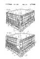
- FIG. 1is a perspective view, illustrating a container constructed as contemplated herein;
- FIG. 2is a perspective view, illustrating the container with one of its walls swung slightly inwardly and with a portion of the wall broken away to illustrate the floor of the container;
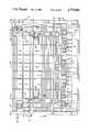
- FIG. 3is a side elevation of the side of the bin in FIGS. 1 and 2 which includes a sectional wall, this side being the side which faces toward the viewer and to the left in FIGS. 1 and 2;
- FIG. 4is a side elevation, illustrating a portion of a detachable access panel in the sectional wall
- FIG. 5is a side elevation, illustrating a portion of the outer frame in the sectional wall of the container
- FIG. 6is a view, taken generally along line 6--6 in FIG. 5;
- FIG. 7is a cross-sectional view, taken along the line 7--7 in FIG. 3;
- FIG. 8is a view, taken generally along the line 8--8 in FIG. 4, illustrating an edge in the access panel
- FIG. 9is a view, taken generally along the line 9--9 in FIG. 8, illustrating the back of the edge of the access panel
- FIG. 10is a view, taken generally along the line 10--10 in FIG. 5, illustrating an edge of a leg in the sectional frame of the wall;
- FIG. 11is a view, taken generally along the line 11--11 in FIG. 10, illustrating the back of the leg in the sectional frame.
- a collapsible bin or containeris shown generally at 10 which includes, in the erected condition illustrated in FIG. 1, a pair of opposed upstanding walls 12, referred to herein arbitrarily as side walls, and extending normal to these side walls 12, a pair of opposed upright walls 14, arbitrarily referred to as end walls.
- the side and end wallsare pivotablymounted on what is referred to herein as a pallet base 16.
- the side and end walls and pallet basemay be formed from a high-density polyethylene as molded parts using injection molding techniques. While theinner surfaces of the side walls and end walls, as well as the surface of the floor 18 of the bin (the floor being part of the pallet base) may be and preferable are formed as smooth, substantially uninterrupted surfaces,the walls and pallet base on their external sides are provided with appropriate strengthening webs distributed thereover as exemplified by thewebs and ridges illustrated at 20 and 22.
- the pallet basein addition to having floor 18, includes a support wall around the bottom periphery thereof and spaced apart openings 24, two per side, which adapt the pallet for lifting by the tines of a fork lift. Withthis organization, the bin may be picked up from any side by a fork lift for transport.
- the side and end wallsmay be pivotably mounted on the pallet base using various forms of hinge or pivot constructions.
- the pivot mounting of the wallsis through hinge structures which are the same as those described in U.S. Pat. No. 4,674,647.
- Hinge structure 26includes a substantially rectangular hinge body 30 extending from the bottom edge of the wall.
- the sides of the hinge bodyare providedwith slots 32 which fit about and thus engage suitable bosses or cylindrical protrusions presented by the pallet base.
- the slotsare open ended on the inward side of the wall, i.e., are U-shaped, to permit by lateral movement of the wall insertion of the bosses into the U-shaped slots.
- Hinge structure 27, used in conjunction with hinge structure 26,may be characterized as a "snap hinge", and has the added function of retaining the wall against removal from the pallet base.
- the hinge structurewhich like hinge structure 26 is molded integral with the wall, has two parts comprising a body 34 and a member 36.
- Body 36is similar to one side of hinge body 30, in that it contains an open ended slot 38 designed to receive a cylindrical hinge boss presented by the pallet base.
- Body 34has a relatively thin walled shank 39 terminating in a cylindrical hub 41 which is provided with a bore 43 for receiving a boss presented by the pallet base. Since shank 39 is somewhat flexible, it may be deformed to such an extent as to allow the boss to engage bore 43 to snap the hub into position.
- pivot axis 46 for the end wall 14 which is closest to the vieweris set forth, such extending across the bin in a horizontal direction and at an elevation which is slightly above the elevation of floor 18.
- a similarly located pivot axisis provided for the other end wall 14. This organization permits the end walls to be collapsed by swinging them inwardly so that both walls extend over the floor, with one wall overlapped and folded over the other wall.
- a similar pivot structuremay be provided for pivotally mounting side walls 12. In the case of the side walls, as exemplified by axis 50, the pivot axes for the walls extend horizontally across the bin but at a slightly higher elevation than axes 46 for walls 14.
- the various side and end wallsare interconnected along adjacent side edgesand with the walls in an upright position, by a joint which is effective tohold the walls upright and prevent them from pivoting outwardly from a vertical.
- the jointalso interlocks the side edges to prevent relative longitudinal displacement.
- flange 64(see FIG. 7) extending substantially its length which projects inwardly from the edge of the sidewall and is parallel to the inner face of side wall 12.
- This flangepartially bounds a groove 66 and is notched at 68 with notches distributedalong its length.
- Webs 70are provided spanning groove 66 which are similarto webs 62 described in connection with end wall 14. With the walls uprightand interconnected by the joint described, flange 64 moves into groove 58 and flange 56 moves into groove 66 with the flanges then lying side by side, the flanges and grooves preventing the respective walls from moving outwardly from a vertical. Interlocking the flanges to prevent relative longitudinal movement of the wall edges are webs 70 fitting within notches60 and webs 62 fitting within notches 68.
- a latch meansis provided at each of the corners of the bin for latching adjacent edges whereby an end wall is held from pivoting inwardly from an upright position.
- a slide latch member 72including a handle portion 74 and an extension 76 joined to the handle portion and projecting to one side thereof.
- the extensionis slidably mounted within an accommodating slot provided in a boss 80 and a reinforcing flange 82 which is part of the end wall, permitting the slide latch member to be shifted from a retracted position to an extended position where the extension such extends beyond the reinforcing flange.
- the end of extension 76moves into a suitable pocket provided in the adjacent edge ofside wall 12, to produce an interlocked connection.
- At least one of the walls of the bin(in the embodiment of the invention herein illustrated such comprising the end wall 14 which faces the viewer in FIG. 2, the wall being shown in greater detail in FIGS. 3-10) be a sectional wall, the wall including an outer frame section which detachablymounts what is referred to herein as a removable access panel.
- the end wallincludes what is referred to herein as an outer frame section 90 having what might be thought of as an inverted yokeshape formed by an elongate bottom expanse 92, and joined to this bottom expanse and projecting upwardly along side margins, leg expanses 94, 96.
- the bottom expanseextends along the wall as such is illustrated approximately in the region delineated between extensions of lines 98 and 100 where such extend across the end wall.
- the two leg expansesextend vertically in the regions approximately delineatedbetween lines 101 and 102 (in the case of leg 94) and lines 103, 104 (in the case of leg 96).
- the opposing legs and bottom expansedefine an opening generally shown at 106 in FIG. 5, this opening being the access opening which receives and is closed off by a detachably mounted access panel, shown at 108 in FIG. 4.
- FIG. 10(a view illustrating leg 94 as viewed from right to left in FIG. 5), FIG. 11 (illustrating the back of leg 94) leg 94is provided with three, what are referred to herein as back-up abutment plate segments 110, 112, 114.
- Eachhas a surface facing the exterior of the outer frame section, as illustrated for plate segment 110 at ll0a, that extends vertically but is recessed well inwardly of the general planeof the exterior of the outer frame section.
- flange surfaces 118, 120Extending partially about the perimeter of each of the plate segments, and as exemplified by segment 110, are flange surfaces 118, 120 extending normal to surface ll0a of the plate segment.
- the flange surfaces together with surface 110adefine a reception pocket recessed inwardly from the exterior surface of the wall frame section. Similar reception pockets are formed in conjunction with back-up abutment plate segments 112, 114.
- Socket structureis provided below each of the reception pockets defined bythe plate segments 110, 112, 114 and associated flange surfaces. Further explaining, and considering the socket structure associated with plate segment 110, shown at 124 is a socket expanse located generally toward theviewer as such is shown in FIG. 5 from plate segment 110.
- the socket expanse on its inner sidei.e., the side facing the interior of the bin, is provided with a tapered recess 125 bottomed by a floor 126 and sides 127, 128, side 127 converging on side 128 progressing downwardly.
- This tapered recessprovides a socket positioned below back-up abutment plate segment 110.
- Similar socketsare provided by socket expanses 130 and 132 located below plate segments 112 and 114.
- leg 96 of the outer frame sectionis provided with back-up abutment plate segments and socket expanses similar to those just described, located on the margin of the leg which borders opening 106.
- Bottom expanse 92is formed with a series of well sockets distributed alongthe length thereof.
- socket wells 134, 136appearing at spaced intervals along the exterior side of the bottom expanse are socket wells 134, 136.
- Eachis defined, as exemplified by well 134, by flange surfaces 140, 142 that converge on each other progressing downwardly, and a flange surface 144 forming the base of the socket well.
- the rear side ofthe socket wellis defined by a surface 146. The socket well opens to the exterior of the bin.
- socket wells 134, 136are wells such as well 150 which face the interior of the bin. These are defined by side surfaces 152, 154 that converge on each other, a backing surface 156, and a floor 158.
- the access panelincludes projecting tongue portions configured to be detachably received within the socket openings provided along the margins of the legs in the outer frame section and within the socket wells which are provided along the upper part of bottom expanse 92.
- tongue projections 160, 162 and 164distributed along the length of the left margin of the access panel as illustrated in FIG. 4 are tongue projections 160, 162 and 164.
- Each, and considering tongue projection 160includes a wall 170 forming the back of the tongue projection, a shoulder 172 adjacent the upper part of the tongue projection extending inwardly from the general plane of the exterior of the access panel, and a wedge or V-shaped tongue 174 extendingdownwardly from shoulder 172 and located in a region slightly to the rear of the exterior surface of the access panel.
- Wall 170has outer dimensionswhich enables such to be fitted within the reception pocket previously described in connection with back-up abutment plate segment 110 defined bythe surface of this plate segment and flange surfaces 118, 120.
- tongue 174becomes positioned over tapered socket opening 125 which is provided in socket expanse 124.
- Tongue projections 162, 164are similarly fitable within reception pockets associated with plate segments 112, 114 of the outer frame section. Further, and while not specifically described, tongue projections along the side margin of the access panel opposite to the one illustrated in FIG. 4 fit within reception pockets provided in the adjacent margin of leg
- the base of the access panelis provided with a series of downwardly projecting tongues 180 projecting downwardly from adjacent the exterior surface of the access panel fitable within socket wells 134, 136. Also projecting downwardly from the bottom of the access panel but spaced rearwardly from the tongues 180 are tongues 182 positioned to be received within the wells 150 provided in the bottom expanse.
- a slide latch member 190including an extension 192 and handle 194, similar to slide latch member 72. Extension 192 is received within an aperture 196. With the access panel in place, the slide latch member is shiftable to the left from the position shown in FIG. 4 to be positioned underneath socket expanse 124 inthe outer frame section. With such positioning, the access panel is latchedin such a manner as to prevent its removal from the outer frame section.
- each edge of the access paneladjacent the top and each edge of the access panel is a protrusion 200 with a wedge element 202 carried on its inner face.
- Each leg(see FIGS. 5 and 11) has a socket recess 204 shaped to receive the wedge element with final positioning of the access panel.
- a web 206extending generally in the plane of the exterior surface of the access panel overlies a shoulder 208 with the access panel finally positioned and in place.
- the access panelis shifted to place it slightly outwardly of the outer frame section and tongue projections 160, 162, 164 on each side of the access panel in frontof and slightly spaced from plate segments 110, 112 and 114.
- the panel and its tongue projectionsthe panel may be moved rearwardly, to place the access panel in the plane of the outer frame section and with its tongue projections lying directly against the plate segments and within the reception pockets associated with the plate segments.
- the tonguesdirectly overlie the tapered sockets exemplified by socket 125 presented along the inner margins of thelegs in the outer frame section.
- Tongues 180, 182 along the bottom edge of the access panelbecome positioned directly over socket wells 134, 150 in the bottom expanse of the outer frame section.
- the various tongues on the side edgesof the access panelbecome seated in tapered sockets 125, and tongues 180, 182 become seated in socket wells 134, 150.
- Walls 170 of the tongue projections, along their rear and upper margins,bear on plate segments 110, 112, 114.
- Tongues 180, 182 at the bottom of the access panelare in straddling relationship with respect to the bottom expanse of the outer frame section.
- the access panelWhen mounted, the panel is firmly locked from movement extending generally normal to the plane of the sectional wall.
- the mounting of the access panelprovides interlocking with the outer frame section at spaced locations distributed about the entire perimeter of the access panel.
- the access panelis first lifted to free the tongue projections from any engagement with the socket expanses 125 and to place them in covering relation over the plate segments 110, 112, 114. This also frees the lower tongues from the wells in the bottom extent of the outer frame section. After being so positioned, the access panel is removed by pulling such forwardly of the exterior surface of the outer frame section in the sectional wall.
Landscapes
- Engineering & Computer Science (AREA)
- Mechanical Engineering (AREA)
- Rigid Containers With Two Or More Constituent Elements (AREA)
Abstract
Description
Claims (4)
Priority Applications (1)
| Application Number | Priority Date | Filing Date | Title |
|---|---|---|---|
| US07/141,722US4775068A (en) | 1988-01-11 | 1988-01-11 | Collapsible container with removable access panel |
Applications Claiming Priority (1)
| Application Number | Priority Date | Filing Date | Title |
|---|---|---|---|
| US07/141,722US4775068A (en) | 1988-01-11 | 1988-01-11 | Collapsible container with removable access panel |
Publications (1)
| Publication Number | Publication Date |
|---|---|
| US4775068Atrue US4775068A (en) | 1988-10-04 |
Family
ID=22496937
Family Applications (1)
| Application Number | Title | Priority Date | Filing Date |
|---|---|---|---|
| US07/141,722Expired - LifetimeUS4775068A (en) | 1988-01-11 | 1988-01-11 | Collapsible container with removable access panel |
Country Status (1)
| Country | Link |
|---|---|
| US (1) | US4775068A (en) |
Cited By (68)
| Publication number | Priority date | Publication date | Assignee | Title |
|---|---|---|---|---|
| US4960223A (en)* | 1989-07-18 | 1990-10-02 | Chiang Pei Lieh | Box crate container |
| EP0385914A3 (en)* | 1989-02-24 | 1990-12-27 | Ropak Corporation | Collapsible container |
| WO1991000222A3 (en)* | 1989-06-22 | 1991-03-07 | Tetra Pak Inc | Folding crate for holding packages |
| US5094356A (en)* | 1990-11-13 | 1992-03-10 | Buckhorn Material Handling Group, Inc. | Knock down bulk container |
| US5114037A (en)* | 1990-06-19 | 1992-05-19 | Perstorp Xytec, Inc. | Container with sidewall extension |
| US5161709A (en)* | 1989-01-30 | 1992-11-10 | World Container Corporation | Hinged collapsible container |
| US5287981A (en)* | 1991-06-28 | 1994-02-22 | A. R. Arena Products, Inc. | Collapsible cheese container |
| US5289935A (en)* | 1991-05-14 | 1994-03-01 | Perstorp Xytec, Inc. | Container with sidewall extension and method for making |
| US5397022A (en)* | 1991-02-22 | 1995-03-14 | Fritz Schafer Gesellschaft Mit Beschrankter Haftung | Box-shaped containers of plastics material |
| US5398835A (en)* | 1993-11-29 | 1995-03-21 | Blinstrub; Robert M. | Collapsible material handling container having improved corner interlock |
| US5425910A (en)* | 1992-12-31 | 1995-06-20 | A. R. Arena Products, Inc. | Resin wall formation for collapsible shipping container |
| US5467885A (en)* | 1993-11-29 | 1995-11-21 | Blinstrub; Robert M. | Collapsible material handling container |
| EP0690003A1 (en) | 1993-11-29 | 1996-01-03 | Otto Industries, Inc. | Collapsible container |
| US5538153A (en)* | 1993-12-30 | 1996-07-23 | Tetra Laval Holdings & Finance Sa | Folding crate for holding packages |
| US5551594A (en)* | 1993-11-08 | 1996-09-03 | Fritz Schafer Gesellschaft Mit Beschrankter Haftung | Box-shaped container of plastics material |
| USD374121S (en) | 1994-08-09 | 1996-10-01 | Perstorp Ab | Pallet container |
| US5586675A (en)* | 1993-11-29 | 1996-12-24 | General Electric Company | Reinforced material handling container |
| USD377269S (en)* | 1994-08-09 | 1997-01-14 | Perstorp Ab | Pallet container |
| USD381202S (en)* | 1994-08-04 | 1997-07-22 | Perstorp Ab | Pallet container |
| USD382401S (en)* | 1995-02-09 | 1997-08-19 | Perstorp Ab | Pallet container |
| US5660291A (en)* | 1991-09-24 | 1997-08-26 | Dash; Alan | Collapsible cage |
| BE1010646A3 (en)* | 1996-09-24 | 1998-11-03 | Overpelt Plascobel Nv | Folding crate |
| US6015056A (en)* | 1997-12-19 | 2000-01-18 | Rehrig Pacific Company | Collapsible container |
| US6029840A (en)* | 1996-04-22 | 2000-02-29 | Perstorp Ab | Collapsible container |
| US6044998A (en)* | 1998-12-23 | 2000-04-04 | Allibert-Contico, L.L.C. | Bin having side access gate |
| US6073790A (en)* | 1996-02-12 | 2000-06-13 | Schoeller-Plast S.A. | Folding container with releasably locking side walls |
| USD446392S1 (en) | 1999-12-27 | 2001-08-14 | Rehrig Pacific Company | Storage container |
| USD452614S1 (en) | 2000-10-28 | 2002-01-01 | Rehrig Pacific Company | Collapsible container |
| US6386388B1 (en) | 1999-12-27 | 2002-05-14 | Rehrig Pacific Company | Container |
| USD458753S1 (en) | 2000-09-21 | 2002-06-18 | Rehrig Pacific Co. | Container |
| US6409041B1 (en) | 2000-09-21 | 2002-06-25 | Rehrig Pacific Company | Container |
| US6416271B1 (en) | 2000-04-07 | 2002-07-09 | Nucon Corporation | Drop box container |
| US6601724B1 (en) | 1999-11-20 | 2003-08-05 | Rehrig Pacific Company | Collapsible merchandizing container |
| US6631822B1 (en) | 2000-10-28 | 2003-10-14 | Rehrig Pacific Company | Collapsible container |
| US6776300B2 (en) | 2000-04-07 | 2004-08-17 | Xytec Systems, Inc. | Collapsible container with closed, multi-paneled sidewalls |
| US20040200833A1 (en)* | 2003-04-09 | 2004-10-14 | George Utz Holding Ag | Stackable transport box |
| US6918502B1 (en) | 1997-12-19 | 2005-07-19 | Rehrig Pacific Company | Collapsible container |
| US20060102633A1 (en)* | 2004-11-16 | 2006-05-18 | Fritz Schafer Gmbh | Stackable storage/transport/stocking box with openable end |
| US20060186072A1 (en)* | 2005-02-07 | 2006-08-24 | Moku Naruishi | Packaging device and buffer |
| JP2006298427A (en)* | 2005-04-20 | 2006-11-02 | Sanko Co Ltd | Box pallet |
| US20070056966A1 (en)* | 2005-09-09 | 2007-03-15 | Fuvi Mechanical Technology Company Limited | Assemble/Disassemble Type Container |
| US20080017081A1 (en)* | 2006-07-24 | 2008-01-24 | Rehrig Pacific Company | Pallet assembly |
| US7331480B1 (en) | 2002-09-27 | 2008-02-19 | Roger Nolan | Articulated hinge apparatus and related methods |
| US20080169285A1 (en)* | 2007-01-16 | 2008-07-17 | Nick Marazita | Collapsible container |
| US20090205169A1 (en)* | 2005-06-03 | 2009-08-20 | Roger Nolan | Container assembly and latch apparatus, and related methods |
| US20090206078A1 (en)* | 2008-02-13 | 2009-08-20 | Goodpack Ltd. | Crates |
| CN100572203C (en)* | 2003-12-05 | 2009-12-23 | 三甲株式会社 | Folding receiver |
| DE102008047859A1 (en)* | 2008-09-18 | 2010-04-08 | Schoeller Arca Systems Gmbh | large containers |
| US7740149B2 (en) | 2002-09-27 | 2010-06-22 | Ropak Corporation | Container sidewall strengthening apparatus and methods |
| US7757876B1 (en) | 2005-05-03 | 2010-07-20 | Material Improvements, LP | Collapsible cheese container |
| US20110094916A1 (en)* | 2006-11-09 | 2011-04-28 | Wolfgang Orgeldinger | Height adjustable transport container |
| US20110108549A1 (en)* | 2008-07-03 | 2011-05-12 | Macro Plastics, Inc. | Shipping container |
| AU2009227869A1 (en)* | 2009-10-19 | 2011-05-12 | K. Hartwall Oy Ab | Collapsible Crate for Transportation and Display of Pieces, and Method for Supplying and Merchandising Products |
| US20110139774A1 (en)* | 2009-12-16 | 2011-06-16 | Roger Nolan | Collapsible Bin |
| US20110180533A1 (en)* | 2010-01-28 | 2011-07-28 | Nova Chemicals (International) S.A | Collapsible refuse bin |
| US8915397B2 (en) | 2012-11-01 | 2014-12-23 | Orbis Corporation | Bulk container with center support between drop door and side wall |
| US8950613B2 (en) | 2011-02-16 | 2015-02-10 | Orbis Corporation | Bulk bin container with removable side wall |
| US20150147112A1 (en)* | 2010-07-13 | 2015-05-28 | A.R. Arena Products, Inc. | Flex assembly of pallet base and deck |
| US9487326B2 (en) | 2013-11-26 | 2016-11-08 | Orbis Corporation | Bulk bin with panel to panel interlock features |
| US9708097B2 (en) | 2013-11-15 | 2017-07-18 | Orbis Corporation | Bulk bin with integrated shock absorber |
| US9863174B2 (en) | 2014-06-20 | 2018-01-09 | Orbis Corporation | Hinge rod trap for a collapsible bin |
| US10065763B2 (en) | 2016-09-15 | 2018-09-04 | Arena Packaging, Llc | Wall latching system |
| US10427837B2 (en) | 2015-04-20 | 2019-10-01 | Orbis Corporation | Container with feature to block fork tine openings |
| US10703531B2 (en) | 2016-03-11 | 2020-07-07 | Rehrig Pacific Company | Collapsible crate with wood appearance |
| CN112601705A (en)* | 2018-07-23 | 2021-04-02 | 世界运输公司 | Collapsible storage and transport unit |
| US20230041887A1 (en)* | 2017-08-31 | 2023-02-09 | Kenneth R Moras Pty Ltd | Reusable bin assembly |
| US11597557B2 (en) | 2018-10-04 | 2023-03-07 | Rehrig Pacific Company | Reconfigurable beverage crate |
| US12168544B2 (en) | 2021-09-16 | 2024-12-17 | Rehrig Pacific Company | Hybrid collapsible crate |
Citations (5)
| Publication number | Priority date | Publication date | Assignee | Title |
|---|---|---|---|---|
| US2780382A (en)* | 1954-10-15 | 1957-02-05 | Tri State Engineering Company | Collapsible container |
| US3861554A (en)* | 1973-10-15 | 1975-01-21 | Banner Metals | Pallet distribution cage |
| US4043476A (en)* | 1976-03-01 | 1977-08-23 | Ateliers Reunis Societe Anonyme | Locking device for goods transporting carts and like receptacles |
| US4591065A (en)* | 1984-09-25 | 1986-05-27 | Foy Dennis M | Foldable container assembly |
| US4674647A (en)* | 1985-06-21 | 1987-06-23 | Xytec Plastics, Inc. | Collapsible storage bin |
- 1988
- 1988-01-11USUS07/141,722patent/US4775068A/ennot_activeExpired - Lifetime
Patent Citations (5)
| Publication number | Priority date | Publication date | Assignee | Title |
|---|---|---|---|---|
| US2780382A (en)* | 1954-10-15 | 1957-02-05 | Tri State Engineering Company | Collapsible container |
| US3861554A (en)* | 1973-10-15 | 1975-01-21 | Banner Metals | Pallet distribution cage |
| US4043476A (en)* | 1976-03-01 | 1977-08-23 | Ateliers Reunis Societe Anonyme | Locking device for goods transporting carts and like receptacles |
| US4591065A (en)* | 1984-09-25 | 1986-05-27 | Foy Dennis M | Foldable container assembly |
| US4674647A (en)* | 1985-06-21 | 1987-06-23 | Xytec Plastics, Inc. | Collapsible storage bin |
Cited By (107)
| Publication number | Priority date | Publication date | Assignee | Title |
|---|---|---|---|---|
| US5161709A (en)* | 1989-01-30 | 1992-11-10 | World Container Corporation | Hinged collapsible container |
| EP0385914A3 (en)* | 1989-02-24 | 1990-12-27 | Ropak Corporation | Collapsible container |
| US5076457A (en)* | 1989-06-22 | 1991-12-31 | Tetra Pak Holdings S.A. | Folding crate for holding packages |
| WO1991000222A3 (en)* | 1989-06-22 | 1991-03-07 | Tetra Pak Inc | Folding crate for holding packages |
| US4960223A (en)* | 1989-07-18 | 1990-10-02 | Chiang Pei Lieh | Box crate container |
| US5114037A (en)* | 1990-06-19 | 1992-05-19 | Perstorp Xytec, Inc. | Container with sidewall extension |
| US5094356A (en)* | 1990-11-13 | 1992-03-10 | Buckhorn Material Handling Group, Inc. | Knock down bulk container |
| US5397022A (en)* | 1991-02-22 | 1995-03-14 | Fritz Schafer Gesellschaft Mit Beschrankter Haftung | Box-shaped containers of plastics material |
| US5289935A (en)* | 1991-05-14 | 1994-03-01 | Perstorp Xytec, Inc. | Container with sidewall extension and method for making |
| US5287981A (en)* | 1991-06-28 | 1994-02-22 | A. R. Arena Products, Inc. | Collapsible cheese container |
| US5660291A (en)* | 1991-09-24 | 1997-08-26 | Dash; Alan | Collapsible cage |
| US5425910A (en)* | 1992-12-31 | 1995-06-20 | A. R. Arena Products, Inc. | Resin wall formation for collapsible shipping container |
| US5551594A (en)* | 1993-11-08 | 1996-09-03 | Fritz Schafer Gesellschaft Mit Beschrankter Haftung | Box-shaped container of plastics material |
| US5467885A (en)* | 1993-11-29 | 1995-11-21 | Blinstrub; Robert M. | Collapsible material handling container |
| EP0690004A1 (en) | 1993-11-29 | 1996-01-03 | Otto Industries, Inc. | Collapsible container |
| EP0690003A1 (en) | 1993-11-29 | 1996-01-03 | Otto Industries, Inc. | Collapsible container |
| US5586675A (en)* | 1993-11-29 | 1996-12-24 | General Electric Company | Reinforced material handling container |
| US5398835A (en)* | 1993-11-29 | 1995-03-21 | Blinstrub; Robert M. | Collapsible material handling container having improved corner interlock |
| US5538153A (en)* | 1993-12-30 | 1996-07-23 | Tetra Laval Holdings & Finance Sa | Folding crate for holding packages |
| USD381202S (en)* | 1994-08-04 | 1997-07-22 | Perstorp Ab | Pallet container |
| USD374121S (en) | 1994-08-09 | 1996-10-01 | Perstorp Ab | Pallet container |
| USD377269S (en)* | 1994-08-09 | 1997-01-14 | Perstorp Ab | Pallet container |
| USD382401S (en)* | 1995-02-09 | 1997-08-19 | Perstorp Ab | Pallet container |
| US6073790A (en)* | 1996-02-12 | 2000-06-13 | Schoeller-Plast S.A. | Folding container with releasably locking side walls |
| US6029840A (en)* | 1996-04-22 | 2000-02-29 | Perstorp Ab | Collapsible container |
| BE1010646A3 (en)* | 1996-09-24 | 1998-11-03 | Overpelt Plascobel Nv | Folding crate |
| US6098827A (en)* | 1997-12-19 | 2000-08-08 | Rehrig Pacific Company | Collapsible container |
| US6015056A (en)* | 1997-12-19 | 2000-01-18 | Rehrig Pacific Company | Collapsible container |
| US6209742B1 (en) | 1997-12-19 | 2001-04-03 | Rehrig Pacific Company | Collapsible container |
| US6918502B1 (en) | 1997-12-19 | 2005-07-19 | Rehrig Pacific Company | Collapsible container |
| US6044998A (en)* | 1998-12-23 | 2000-04-04 | Allibert-Contico, L.L.C. | Bin having side access gate |
| US6601724B1 (en) | 1999-11-20 | 2003-08-05 | Rehrig Pacific Company | Collapsible merchandizing container |
| US6398054B1 (en) | 1999-12-27 | 2002-06-04 | Rehrig Pacific Co. | Collapsible container |
| US6386388B1 (en) | 1999-12-27 | 2002-05-14 | Rehrig Pacific Company | Container |
| US20020158067A1 (en)* | 1999-12-27 | 2002-10-31 | Rehrig Pacific Company | Collapsible container |
| US7044319B2 (en) | 1999-12-27 | 2006-05-16 | Rehrig Pacific Company | Collapsible container |
| USD446392S1 (en) | 1999-12-27 | 2001-08-14 | Rehrig Pacific Company | Storage container |
| US6776300B2 (en) | 2000-04-07 | 2004-08-17 | Xytec Systems, Inc. | Collapsible container with closed, multi-paneled sidewalls |
| US6416271B1 (en) | 2000-04-07 | 2002-07-09 | Nucon Corporation | Drop box container |
| US20020148859A1 (en)* | 2000-04-07 | 2002-10-17 | Pigott Maurice J. | Drop box container |
| US7017765B2 (en) | 2000-04-16 | 2006-03-28 | Rehrig Pacific Company | Container |
| US20020130132A1 (en)* | 2000-04-16 | 2002-09-19 | Rehrig Pacific Company | Container |
| US6409041B1 (en) | 2000-09-21 | 2002-06-25 | Rehrig Pacific Company | Container |
| US7086555B2 (en) | 2000-09-21 | 2006-08-08 | Rehrig Pacific Company | Container |
| USD478421S1 (en) | 2000-09-21 | 2003-08-19 | Rehrig Pacific Company | Container |
| USD458753S1 (en) | 2000-09-21 | 2002-06-18 | Rehrig Pacific Co. | Container |
| US6631822B1 (en) | 2000-10-28 | 2003-10-14 | Rehrig Pacific Company | Collapsible container |
| US7128231B2 (en) | 2000-10-28 | 2006-10-31 | Rehrig Pacific Company | Collapsible container |
| USD452614S1 (en) | 2000-10-28 | 2002-01-01 | Rehrig Pacific Company | Collapsible container |
| US20040099662A1 (en)* | 2000-10-28 | 2004-05-27 | Rehrig Pacific Company | Collapsible container |
| US20090152265A1 (en)* | 2002-09-27 | 2009-06-18 | Orbis Corporation | Articulated hinge apparatus and related methods |
| US7828167B2 (en) | 2002-09-27 | 2010-11-09 | Roger Nolan | Articulated hinge apparatus and related methods |
| US7740149B2 (en) | 2002-09-27 | 2010-06-22 | Ropak Corporation | Container sidewall strengthening apparatus and methods |
| US7331480B1 (en) | 2002-09-27 | 2008-02-19 | Roger Nolan | Articulated hinge apparatus and related methods |
| US20040200833A1 (en)* | 2003-04-09 | 2004-10-14 | George Utz Holding Ag | Stackable transport box |
| US7416092B2 (en)* | 2003-04-09 | 2008-08-26 | George Utz Holding Ag | Stackable transport box |
| CN100572203C (en)* | 2003-12-05 | 2009-12-23 | 三甲株式会社 | Folding receiver |
| US20060102633A1 (en)* | 2004-11-16 | 2006-05-18 | Fritz Schafer Gmbh | Stackable storage/transport/stocking box with openable end |
| US7617947B2 (en)* | 2004-11-16 | 2009-11-17 | Fritz Schafer Gmbh | Stackable storage/transport/stocking box with openable end |
| US20060186072A1 (en)* | 2005-02-07 | 2006-08-24 | Moku Naruishi | Packaging device and buffer |
| US7798352B2 (en)* | 2005-02-07 | 2010-09-21 | Ricoh Company, Ltd. | Packaging device and buffer |
| JP2006298427A (en)* | 2005-04-20 | 2006-11-02 | Sanko Co Ltd | Box pallet |
| US7757876B1 (en) | 2005-05-03 | 2010-07-20 | Material Improvements, LP | Collapsible cheese container |
| US9079684B2 (en) | 2005-05-03 | 2015-07-14 | Buckhorn, Inc. | Collapsible cheese container |
| US20100239730A1 (en)* | 2005-05-03 | 2010-09-23 | Material Improvements, LP | Collapsible cheese container |
| US9422082B2 (en) | 2005-06-03 | 2016-08-23 | Roger Nolan | Container assembly and latch apparatus, and related methods |
| US20090205169A1 (en)* | 2005-06-03 | 2009-08-20 | Roger Nolan | Container assembly and latch apparatus, and related methods |
| US20070056966A1 (en)* | 2005-09-09 | 2007-03-15 | Fuvi Mechanical Technology Company Limited | Assemble/Disassemble Type Container |
| US20100212553A1 (en)* | 2006-07-24 | 2010-08-26 | Baltz Kyle L | Pallet assembly |
| US7748329B2 (en) | 2006-07-24 | 2010-07-06 | Rehrig Pacific Company | Pallet assembly |
| US20080017081A1 (en)* | 2006-07-24 | 2008-01-24 | Rehrig Pacific Company | Pallet assembly |
| US20110094916A1 (en)* | 2006-11-09 | 2011-04-28 | Wolfgang Orgeldinger | Height adjustable transport container |
| US9302811B2 (en)* | 2006-11-09 | 2016-04-05 | Ifco Systems Gmbh | Transport container system with stackable crate having movable attachment elements for height adjustment |
| US20080169285A1 (en)* | 2007-01-16 | 2008-07-17 | Nick Marazita | Collapsible container |
| US20090206078A1 (en)* | 2008-02-13 | 2009-08-20 | Goodpack Ltd. | Crates |
| USRE47210E1 (en)* | 2008-02-13 | 2019-01-22 | Goodpack Ibc (Singapore) Pte. Ltd. | Crates |
| US8573427B2 (en)* | 2008-02-13 | 2013-11-05 | Goodpack Limited | Crates |
| US8434618B2 (en)* | 2008-07-03 | 2013-05-07 | Macro Plastics, Inc. | Shipping container |
| US20110108549A1 (en)* | 2008-07-03 | 2011-05-12 | Macro Plastics, Inc. | Shipping container |
| US20110220643A1 (en)* | 2008-09-18 | 2011-09-15 | Schoeller Arca Systems Gmbh | High-capacity container |
| US8511496B2 (en) | 2008-09-18 | 2013-08-20 | Schoeller Arca Systems Gmbh | High-capacity container |
| DE102008047859A1 (en)* | 2008-09-18 | 2010-04-08 | Schoeller Arca Systems Gmbh | large containers |
| AU2009227869A1 (en)* | 2009-10-19 | 2011-05-12 | K. Hartwall Oy Ab | Collapsible Crate for Transportation and Display of Pieces, and Method for Supplying and Merchandising Products |
| US8413831B2 (en) | 2009-12-16 | 2013-04-09 | Orbis Corporation | Collapsible bin |
| US8727158B2 (en) | 2009-12-16 | 2014-05-20 | Orbis Corporation | Bulk container with angled side wall to base installation |
| US8820560B2 (en) | 2009-12-16 | 2014-09-02 | Orbis Corporation | Collapsible bin |
| US20110139775A1 (en)* | 2009-12-16 | 2011-06-16 | Roger Nolan | Fork Tine Notch |
| US20110139774A1 (en)* | 2009-12-16 | 2011-06-16 | Roger Nolan | Collapsible Bin |
| US9415898B2 (en) | 2009-12-16 | 2016-08-16 | Orbis Corporation | Bulk container with angled side wall to base installation |
| US20110180533A1 (en)* | 2010-01-28 | 2011-07-28 | Nova Chemicals (International) S.A | Collapsible refuse bin |
| US8770421B2 (en) | 2010-01-28 | 2014-07-08 | Nova Chemicals (International) S.A. | Collapsible refuse bin |
| US9771178B2 (en)* | 2010-07-13 | 2017-09-26 | A.R. Arena Products, Inc. | Flex assembly of pallet base and deck |
| US20150147112A1 (en)* | 2010-07-13 | 2015-05-28 | A.R. Arena Products, Inc. | Flex assembly of pallet base and deck |
| US8950613B2 (en) | 2011-02-16 | 2015-02-10 | Orbis Corporation | Bulk bin container with removable side wall |
| US9296557B2 (en) | 2012-11-01 | 2016-03-29 | Orbis Corporation | Bulk container with center support between drop door and side wall |
| US8915397B2 (en) | 2012-11-01 | 2014-12-23 | Orbis Corporation | Bulk container with center support between drop door and side wall |
| US9708097B2 (en) | 2013-11-15 | 2017-07-18 | Orbis Corporation | Bulk bin with integrated shock absorber |
| US9487326B2 (en) | 2013-11-26 | 2016-11-08 | Orbis Corporation | Bulk bin with panel to panel interlock features |
| US9863174B2 (en) | 2014-06-20 | 2018-01-09 | Orbis Corporation | Hinge rod trap for a collapsible bin |
| US10427837B2 (en) | 2015-04-20 | 2019-10-01 | Orbis Corporation | Container with feature to block fork tine openings |
| US10703531B2 (en) | 2016-03-11 | 2020-07-07 | Rehrig Pacific Company | Collapsible crate with wood appearance |
| US10065763B2 (en) | 2016-09-15 | 2018-09-04 | Arena Packaging, Llc | Wall latching system |
| US20230041887A1 (en)* | 2017-08-31 | 2023-02-09 | Kenneth R Moras Pty Ltd | Reusable bin assembly |
| US11772844B2 (en)* | 2017-08-31 | 2023-10-03 | Kenneth R Moras Pty Ltd. | Reusable bin assembly |
| CN112601705A (en)* | 2018-07-23 | 2021-04-02 | 世界运输公司 | Collapsible storage and transport unit |
| US11597557B2 (en) | 2018-10-04 | 2023-03-07 | Rehrig Pacific Company | Reconfigurable beverage crate |
| US12168544B2 (en) | 2021-09-16 | 2024-12-17 | Rehrig Pacific Company | Hybrid collapsible crate |
Similar Documents
| Publication | Publication Date | Title |
|---|---|---|
| US4775068A (en) | Collapsible container with removable access panel | |
| US6405888B1 (en) | Collapsible container | |
| US6098827A (en) | Collapsible container | |
| US6918502B1 (en) | Collapsible container | |
| US5671857A (en) | Collapsible container | |
| JP3093901B2 (en) | Synthetic resin container with foldable side walls, especially for storing vegetables | |
| US6036049A (en) | Reusable produce crate | |
| US6216872B1 (en) | Stackable container suitable for transporting produce | |
| US4508237A (en) | Collapsible container | |
| US5398835A (en) | Collapsible material handling container having improved corner interlock | |
| US20030136781A1 (en) | Folding crate | |
| US7032765B2 (en) | Container with over center corner latches | |
| US4776481A (en) | Container construction | |
| CA2136554C (en) | Collapsible container | |
| US20170361982A1 (en) | A Storage and Display Device and System | |
| EP3259195B1 (en) | Heavy-duty foldable storage bin | |
| JP2899560B2 (en) | Stackable containers | |
| JP4689069B2 (en) | Folding container | |
| JP3157071B2 (en) | Folding container made of synthetic resin | |
| JP3157072B2 (en) | Folding container | |
| JPH05139441A (en) | Folding case made of foaming synthetic resin | |
| WO2003039978A1 (en) | Collapsible container | |
| AU9136001A (en) | Collapsible container | |
| JPH11508864A (en) | Foldable container for transporting goods | |
| JP2003335332A (en) | Folding container |
Legal Events
| Date | Code | Title | Description |
|---|---|---|---|
| AS | Assignment | Owner name:XYTEC PLASTICS, INC., TACOMA, PIERCE, WASHINGTON, Free format text:ASSIGNMENT OF ASSIGNORS INTEREST.;ASSIGNORS:REILAND, CHERYL;HILLIS, MARK;MALMANGER, JOHN A.;REEL/FRAME:004828/0096;SIGNING DATES FROM | |
| STCF | Information on status: patent grant | Free format text:PATENTED CASE | |
| AS | Assignment | Owner name:PERSTORP XYTEC, INC., A CORP. OF DE, WASHINGTON Free format text:ASSIGNMENT OF ASSIGNORS INTEREST.;ASSIGNOR:XYTEC PLASTICS, INC.;REEL/FRAME:005895/0639 Effective date:19911029 | |
| FEPP | Fee payment procedure | Free format text:PAT HLDR NO LONGER CLAIMS SMALL ENT STAT AS SMALL BUSINESS (ORIGINAL EVENT CODE: LSM2); ENTITY STATUS OF PATENT OWNER: LARGE ENTITY Free format text:PAYOR NUMBER ASSIGNED (ORIGINAL EVENT CODE: ASPN); ENTITY STATUS OF PATENT OWNER: LARGE ENTITY | |
| FPAY | Fee payment | Year of fee payment:4 | |
| FPAY | Fee payment | Year of fee payment:8 | |
| FPAY | Fee payment | Year of fee payment:12 | |
| AS | Assignment | Owner name:ARCA XYTEC SYSTEMS, INC., WASHINGTON Free format text:ASSIGNMENT OF ASSIGNORS INTEREST;ASSIGNOR:PERSTORP XYTEC, INC.;REEL/FRAME:019246/0377 Effective date:19991116 Owner name:SCHOELLER ARCA SYSTEMS, INC., WASHINGTON Free format text:CHANGE OF NAME;ASSIGNOR:ARCA XYTEC SYSTEMS, INC.;REEL/FRAME:019246/0362 Effective date:20050307 | |
| AS | Assignment | Owner name:SCHOELLER ARCA SYSTEMS, INC., MICHIGAN Free format text:CHANGE OF NAME;ASSIGNOR:ARCA XYTEC SYSTEMS, INC.;REEL/FRAME:021185/0672 Effective date:20050307 | |
| AS | Assignment | Owner name:SCHOELLER ARCA SYSTEMS, INC., MICHIGAN Free format text:CORRECTIVE ASSIGNMENT TO CORRECT THE CORRECT THE ADDRESS OF THE ASSIGNEE PREVIOUSLY RECORDED ON REEL 019246 FRAME 0362. ASSIGNOR(S) HEREBY CONFIRMS THE ADDRESS OF ASSIGNEE SHOULD BE CORRECTED TO READ;ASSIGNOR:ARCA XYTEC SYSTEMS, INC.;REEL/FRAME:021502/0953 Effective date:20050307 Owner name:SCHOELLER ARCA SYSTEMS, INC., MICHIGAN Free format text:CORRECTIVE ASSIGNMENT TO CORRECT THE CORRECT THE ADDRESS OF THE ASSIGNEE PREVIOUSLY RECORDED ON REEL 019246 FRAME 0362;ASSIGNOR:ARCA XYTEC SYSTEMS, INC.;REEL/FRAME:021502/0953 Effective date:20050307 |