US4774919A - Combustion chamber importing system for two-cycle diesel engine - Google Patents
Combustion chamber importing system for two-cycle diesel engineDownload PDFInfo
- Publication number
- US4774919A US4774919AUS07/092,161US9216187AUS4774919AUS 4774919 AUS4774919 AUS 4774919AUS 9216187 AUS9216187 AUS 9216187AUS 4774919 AUS4774919 AUS 4774919A
- Authority
- US
- United States
- Prior art keywords
- cylinder
- cylinder bore
- cylinder head
- port means
- throat
- Prior art date
- Legal status (The legal status is an assumption and is not a legal conclusion. Google has not performed a legal analysis and makes no representation as to the accuracy of the status listed.)
- Expired - Lifetime
Links
Images

Classifications
- F—MECHANICAL ENGINEERING; LIGHTING; HEATING; WEAPONS; BLASTING
- F02—COMBUSTION ENGINES; HOT-GAS OR COMBUSTION-PRODUCT ENGINE PLANTS
- F02F—CYLINDERS, PISTONS OR CASINGS, FOR COMBUSTION ENGINES; ARRANGEMENTS OF SEALINGS IN COMBUSTION ENGINES
- F02F1/00—Cylinders; Cylinder heads
- F02F1/18—Other cylinders
- F02F1/22—Other cylinders characterised by having ports in cylinder wall for scavenging or charging
- F—MECHANICAL ENGINEERING; LIGHTING; HEATING; WEAPONS; BLASTING
- F02—COMBUSTION ENGINES; HOT-GAS OR COMBUSTION-PRODUCT ENGINE PLANTS
- F02B—INTERNAL-COMBUSTION PISTON ENGINES; COMBUSTION ENGINES IN GENERAL
- F02B25/00—Engines characterised by using fresh charge for scavenging cylinders
- F02B25/14—Engines characterised by using fresh charge for scavenging cylinders using reverse-flow scavenging, e.g. with both outlet and inlet ports arranged near bottom of piston stroke
- F02B25/18—Engines characterised by using fresh charge for scavenging cylinders using reverse-flow scavenging, e.g. with both outlet and inlet ports arranged near bottom of piston stroke the charge flowing upward essentially along cylinder wall adjacent the inlet ports, e.g. by means of deflection rib on piston
- F—MECHANICAL ENGINEERING; LIGHTING; HEATING; WEAPONS; BLASTING
- F02—COMBUSTION ENGINES; HOT-GAS OR COMBUSTION-PRODUCT ENGINE PLANTS
- F02B—INTERNAL-COMBUSTION PISTON ENGINES; COMBUSTION ENGINES IN GENERAL
- F02B75/00—Other engines
- F02B75/02—Engines characterised by their cycles, e.g. six-stroke
- F02B2075/022—Engines characterised by their cycles, e.g. six-stroke having less than six strokes per cycle
- F02B2075/025—Engines characterised by their cycles, e.g. six-stroke having less than six strokes per cycle two
- F—MECHANICAL ENGINEERING; LIGHTING; HEATING; WEAPONS; BLASTING
- F02—COMBUSTION ENGINES; HOT-GAS OR COMBUSTION-PRODUCT ENGINE PLANTS
- F02B—INTERNAL-COMBUSTION PISTON ENGINES; COMBUSTION ENGINES IN GENERAL
- F02B2275/00—Other engines, components or details, not provided for in other groups of this subclass
- F02B2275/16—Indirect injection
- F—MECHANICAL ENGINEERING; LIGHTING; HEATING; WEAPONS; BLASTING
- F02—COMBUSTION ENGINES; HOT-GAS OR COMBUSTION-PRODUCT ENGINE PLANTS
- F02B—INTERNAL-COMBUSTION PISTON ENGINES; COMBUSTION ENGINES IN GENERAL
- F02B3/00—Engines characterised by air compression and subsequent fuel addition
- F02B3/06—Engines characterised by air compression and subsequent fuel addition with compression ignition
- Y—GENERAL TAGGING OF NEW TECHNOLOGICAL DEVELOPMENTS; GENERAL TAGGING OF CROSS-SECTIONAL TECHNOLOGIES SPANNING OVER SEVERAL SECTIONS OF THE IPC; TECHNICAL SUBJECTS COVERED BY FORMER USPC CROSS-REFERENCE ART COLLECTIONS [XRACs] AND DIGESTS
- Y02—TECHNOLOGIES OR APPLICATIONS FOR MITIGATION OR ADAPTATION AGAINST CLIMATE CHANGE
- Y02T—CLIMATE CHANGE MITIGATION TECHNOLOGIES RELATED TO TRANSPORTATION
- Y02T10/00—Road transport of goods or passengers
- Y02T10/10—Internal combustion engine [ICE] based vehicles
- Y02T10/12—Improving ICE efficiencies
Definitions
- This inventionrelates to an improved combustion chamber system for a two-cycle diesel engine and more particularly to an improved porting and combustion system for such an engine that will improve scavenging.
- This inventionis adapted to be embodied in a two-cycle crankcase compression internal combustion engine that is comprised of a cylinder having a cylinder bore, a piston reciprocating in the cylinder bore and a cylinder head that is affixed to the cylinder.
- Exhaust portmeans open into the cylinder bore in one side thereof and scavenge port means open into the cyliner bore and are configured to direct the flow of charge from the crankcase toward the portion of the cylinder bore diametrically opposed to the exhaust means port and directed upwardly toward the cylinder head.
- a chamberis formed in the cylinder head and communicates with the cylinder bore through a restricted throat. The throat is directed toward the diametrically opposed portion of the cylinder bore and means are incorporated for initiating combustion in the cylinder head chamber.
- FIG. 1is a vertical cross-sectional view taken through a single cylinder of an internal combustion engine constructed in accordance with an embodiment of the invention.
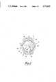
- FIG. 2is a cross-sectional view taken along a line 2--2 of FIG. 1.
- the reference numeral 11indicates generally a two-cycle crankcase compression diesel engine constructed in accordance with an embodiment of the invention.
- the engine 11is depicted as being of the single-cylinder type. It should be readily apparent to those skilled in the art, however, that the invention may be applied to engines having other cylinder numbers and various cylinder configurations such as in-line engines, V-type engines and opposed engines.
- the engine 11is comprised of a cylinder block, indicated generally by the reference numeral 12 that defines a cylinder 13 in which a liner 14 is received and which forms a cylinder bore 15.
- the engine 11is of the air-cooled type and to this end, the cylinder 13 is provided with a plurality of cooling fins 16.
- a piston 17is supported for reciprocation within the cylinder bore 15 and is connected by means of a piston pin 18 to the upper end of a connecting rod 19.
- the lower end of the connecting rod 19is journaled on a throw 21 of a crankshaft 22.
- the crankshaft 22is rotatably journaled within a crankcase chamber 23 that is formed by the cylinder block 12 and a crankcase 24 that is affixed in any known manner to the cylinder block 12.
- the crankshaft 22has main bearing portions 25 that are suitably journaled within the crankcase by bearings supported between the crankcase 24 and cylinder block 12 in a known manner.
- a fly wheel portion 26is formed on the crankshaft 22 for a known purpose.
- the upper end of the cylinder bore 15is closed by means of a cylinder head, indicated generally the reference numeral 27 that is affixed to the cylinder block 12 in a known manner as by means of studs 28 and nuts 29.
- the cylinder head 27cooperates with the cylinder block and specifically the cylinder bore 15 and the area above the head of the piston 17 to form a main combustion chamber, indicated generally by the reference numeral 31.
- the piston 17contains piston rings 32 that sealingly engage the cylinder liner 14 so as to seal the combustion chamber 31.
- the cylinder head 27is also formed with cooling fins 32 for the air cooling thereof.
- a precombustion or torch chamber 33is formed within the cylinder head 27 by means of cooperating first and second inserts 34 and 35 that are fixed in a suitable manner in the cylinder head 27.
- the chamber 33has a relatively small volume and communicates with the main combustion chamber 31 through a throat portion 36 that is oriented in a manner to be described so as to asist in the scavenging of the combustion chamber 31 at the end of the combustion cycle.
- a fuel injection nozzle 37is affixed to the cylinder head 27 and discharges into the precombustion chamber 33. Fuel is supplied to the fuel injection nozzle 37 in a suitable manner.
- a fresh air chargeis delivered to the crankcase chamber 23 during the upward movement of the piston 17 from an air inlet device (not shown) through an intake port 38 that is formed in the cylinder block 12.
- a reed-type valve 39is positioned at the inlet to the intake port 38 so as to prevent any reverse flow.
- the downstream end of the intake port 38communicates with the crankcase chamber 23 as the piston 17 approaches its top dead center position.
- a plurality of main scavenge passagesextend from the crankcase chamber 23 through the cylinder block 12 and cylinder liner 14 and discharge into the combustion chamber 31 when the piston 17 approaches its bottom dead center position.
- the main scavenge ports 41are configured so as to direct the intake charge in the direction indicated by the arrows in FIGS. 1 and 2 toward one side of the cylinder bore 15 and in an upward fashion. As a result, the intake charge is deflected by the cylinder bore 14 in an upward direction toward the lower surface of the cylinder head 27 and in proximity to the discharge end of the throat 36.
- An auxiliary or boost intake port 42extends directly from the main intake port 38 into the combustion chamber 31 and is also configured so as to assist the direction of flow of the intake charge as aforedescribed.
- An exhaust passage 43opens through the side of the cylinder bore 15 diametrically opposed to the area of the cylinder bore 15 where the fresh air scavenge charge impinges.
- the exhaust passage 43terminates in an exhaust port 44 that is formed in the cylinder liner 14 on this diametrically opposed side.
- the intake chargewill flow into the combustion chamber 31 in the direction of the arrows.
- the injection nozzle 37will discharge and ignition will begin in the precombustion or chamber 33.
- the gasesburn and expand in the chamber 33, they will be discharged through the throat 36 in the direction of the line C in FIG. 1 toward the area of the cylinder bore 15 that is impinged upon by the fresh air charge. This will cause the gases to be turned and directed toward the exhaust port 44 and exhaust passage 43 so as to substantially improve scavenging.
- the throat 36is offset at a distance L from the cylinder bore diameter D to one side of the cylinder bore axis so as to assist in this flow direction. Because of this arrangement, the gases will be directed in such a way that there will be a minimum discharge of fresh air charge out of the exhaust port 44 and exhaust passage 43 during engine operation and hence, extremely good efficiency will result.
Landscapes
- Engineering & Computer Science (AREA)
- Chemical & Material Sciences (AREA)
- Combustion & Propulsion (AREA)
- Mechanical Engineering (AREA)
- General Engineering & Computer Science (AREA)
- Combustion Methods Of Internal-Combustion Engines (AREA)
Abstract
Description
This invention relates to an improved combustion chamber system for a two-cycle diesel engine and more particularly to an improved porting and combustion system for such an engine that will improve scavenging.
The advantages of two-cycle engines are well know. Because of their simple construction and high output, they lend themselves to application for a wide variety of purposes. However, the simplified porting arrangement and two-cycle operation gives rise to certain problems in connection with these engines. Specifically, since the intake charge is delivered to the combustion chamber at the same that the exhaust is being discharged, good scavenging is extremely important. The porting configuration and associated cooperation with the combustion chamber should be such that all of the burnt combustion products from the previous cycle are purged from the combustion chamber and also that none of the fresh charge passes out of the exhaust port this operation. This is an extremely difficult problem. When the engine is operated on the diesel principle, these problems become even more acute due to the form of combustion which occurs in the diesel cycle.
It is, therefore, a principle object of this invention to provide an improved combustion chamber and porting configuration for a two-cycle engine.
It is a further object of this invention to provide an improved porting arrangement and combustion chamber for a two-cycle diesel engine wherein good scavenging is assured.
This invention is adapted to be embodied in a two-cycle crankcase compression internal combustion engine that is comprised of a cylinder having a cylinder bore, a piston reciprocating in the cylinder bore and a cylinder head that is affixed to the cylinder. Exhaust port means open into the cylinder bore in one side thereof and scavenge port means open into the cyliner bore and are configured to direct the flow of charge from the crankcase toward the portion of the cylinder bore diametrically opposed to the exhaust means port and directed upwardly toward the cylinder head. A chamber is formed in the cylinder head and communicates with the cylinder bore through a restricted throat. The throat is directed toward the diametrically opposed portion of the cylinder bore and means are incorporated for initiating combustion in the cylinder head chamber.
FIG. 1 is a vertical cross-sectional view taken through a single cylinder of an internal combustion engine constructed in accordance with an embodiment of the invention.
FIG. 2 is a cross-sectional view taken along aline 2--2 of FIG. 1.
In the drawings, the reference numeral 11 indicates generally a two-cycle crankcase compression diesel engine constructed in accordance with an embodiment of the invention. The engine 11 is depicted as being of the single-cylinder type. It should be readily apparent to those skilled in the art, however, that the invention may be applied to engines having other cylinder numbers and various cylinder configurations such as in-line engines, V-type engines and opposed engines.
The engine 11 is comprised of a cylinder block, indicated generally by thereference numeral 12 that defines acylinder 13 in which aliner 14 is received and which forms acylinder bore 15. In the illustrated embodiment, the engine 11 is of the air-cooled type and to this end, thecylinder 13 is provided with a plurality ofcooling fins 16.
Apiston 17 is supported for reciprocation within thecylinder bore 15 and is connected by means of apiston pin 18 to the upper end of a connectingrod 19. The lower end of the connectingrod 19 is journaled on athrow 21 of acrankshaft 22. Thecrankshaft 22 is rotatably journaled within acrankcase chamber 23 that is formed by thecylinder block 12 and acrankcase 24 that is affixed in any known manner to thecylinder block 12. Thecrankshaft 22 has main bearingportions 25 that are suitably journaled within the crankcase by bearings supported between thecrankcase 24 andcylinder block 12 in a known manner. In addition, afly wheel portion 26 is formed on thecrankshaft 22 for a known purpose.
The upper end of thecylinder bore 15 is closed by means of a cylinder head, indicated generally thereference numeral 27 that is affixed to thecylinder block 12 in a known manner as by means ofstuds 28 andnuts 29. Thecylinder head 27 cooperates with the cylinder block and specifically the cylinder bore 15 and the area above the head of thepiston 17 to form a main combustion chamber, indicated generally by thereference numeral 31. It should be noted that thepiston 17 containspiston rings 32 that sealingly engage thecylinder liner 14 so as to seal thecombustion chamber 31. Thecylinder head 27 is also formed withcooling fins 32 for the air cooling thereof.
A precombustion or torch chamber 33 is formed within thecylinder head 27 by means of cooperating first andsecond inserts cylinder head 27. The chamber 33 has a relatively small volume and communicates with themain combustion chamber 31 through athroat portion 36 that is oriented in a manner to be described so as to asist in the scavenging of thecombustion chamber 31 at the end of the combustion cycle.
Afuel injection nozzle 37 is affixed to thecylinder head 27 and discharges into the precombustion chamber 33. Fuel is supplied to thefuel injection nozzle 37 in a suitable manner.
A fresh air charge is delivered to thecrankcase chamber 23 during the upward movement of thepiston 17 from an air inlet device (not shown) through anintake port 38 that is formed in thecylinder block 12. A reed-type valve 39 is positioned at the inlet to theintake port 38 so as to prevent any reverse flow. The downstream end of theintake port 38 communicates with thecrankcase chamber 23 as thepiston 17 approaches its top dead center position.
A plurality of main scavenge passages extend from thecrankcase chamber 23 through thecylinder block 12 andcylinder liner 14 and discharge into thecombustion chamber 31 when thepiston 17 approaches its bottom dead center position. Themain scavenge ports 41 are configured so as to direct the intake charge in the direction indicated by the arrows in FIGS. 1 and 2 toward one side of the cylinder bore 15 and in an upward fashion. As a result, the intake charge is deflected by the cylinder bore 14 in an upward direction toward the lower surface of thecylinder head 27 and in proximity to the discharge end of thethroat 36.
An auxiliary orboost intake port 42 extends directly from themain intake port 38 into thecombustion chamber 31 and is also configured so as to assist the direction of flow of the intake charge as aforedescribed.
Anexhaust passage 43 opens through the side of the cylinder bore 15 diametrically opposed to the area of the cylinder bore 15 where the fresh air scavenge charge impinges. Theexhaust passage 43 terminates in anexhaust port 44 that is formed in thecylinder liner 14 on this diametrically opposed side.
When thepiston 17 begins its downward stroke and after thescavenge ports 41 andboost port 42 are opened, the intake charge will flow into thecombustion chamber 31 in the direction of the arrows. As thepistons 17 begins its upward stroke and at the appropriate time, theinjection nozzle 37 will discharge and ignition will begin in the precombustion or chamber 33. As the gases burn and expand in the chamber 33, they will be discharged through thethroat 36 in the direction of the line C in FIG. 1 toward the area of thecylinder bore 15 that is impinged upon by the fresh air charge. This will cause the gases to be turned and directed toward theexhaust port 44 andexhaust passage 43 so as to substantially improve scavenging. It should be noted that thethroat 36 is offset at a distance L from the cylinder bore diameter D to one side of the cylinder bore axis so as to assist in this flow direction. Because of this arrangement, the gases will be directed in such a way that there will be a minimum discharge of fresh air charge out of theexhaust port 44 andexhaust passage 43 during engine operation and hence, extremely good efficiency will result.
It is to be understood that the foregoing description is that of a preferred embodiment of the invention and that various changes and modifications may be made without departing from the spirit and scope of the invention, as defined by the appended claims.
Claims (5)
1. In a two-cycle crankcase compression internal combustion engine comprised of a cylinder having a cylinder bore, a piston reciprocating in said cylinder bore, a cylinder head affixed to said cylinder, exhaust port means opening into said cylinder bore at one side thereof, scavenge port means opening into said cylinder bore at a point spaced from said exhaust port means and configured to direct the flow of a charge from said crankcase toward the portion of said cylinder bore diametrically opposed to said exhaust port means and directed upwardly towards said cylinder head, a chamber formed within said cylinder head and communicating with said cylinder bore through a restricted throat, said throat being offset from said diametrically opposed portion of said cylinder bore and directed at an angle toward said diametrically opposed portion of said cylinder bore, said throat being disposed so as to direct the flow of expanding gases from said cylinder head chamber toward said diameterically opposed portion of said cylinder bore for redirecting the flow toward said exhaust port means, and means for initiating combustion in said cylinder head chamber.
2. In a two-cycle crankcase compression internal combustion engine as set forth in claim 1, wherein the scavenge port means and throat are directed so that their flow impinge upon the same area of the cylinder bore.
3. In a two-cycle crankcase compression internal combustion engine as set forth in claim 1, wherein the means for initiating combustion in the cylinder head chamber comprises a fuel injection nozzle for causing self-ignition for operating on a diesel cycle.
4. In a two-cycle crankcase compression internal combustion engine as set forth in claim 3 wherein the fuel injection nozzle discharges directly into the cylinder head chamber.
5. In a two-cycle crankcase compression internal combustion engine as set forth in claim 4, wherein the scavenge port means and throat are directed so that their flow impinge upon the same area of the cylinder bore.
Applications Claiming Priority (4)
| Application Number | Priority Date | Filing Date | Title |
|---|---|---|---|
| JP20965486AJPS6365118A (en) | 1986-09-08 | 1986-09-08 | Two-cycle diesel engine |
| JP61-209654 | 1986-09-08 | ||
| JP22208186AJPH0768899B2 (en) | 1986-09-22 | 1986-09-22 | 2-cycle diesel engine |
| JP61-222081 | 1986-09-22 |
Publications (1)
| Publication Number | Publication Date |
|---|---|
| US4774919Atrue US4774919A (en) | 1988-10-04 |
Family
ID=26517581
Family Applications (1)
| Application Number | Title | Priority Date | Filing Date |
|---|---|---|---|
| US07/092,161Expired - LifetimeUS4774919A (en) | 1986-09-08 | 1987-09-02 | Combustion chamber importing system for two-cycle diesel engine |
Country Status (1)
| Country | Link |
|---|---|
| US (1) | US4774919A (en) |
Cited By (45)
| Publication number | Priority date | Publication date | Assignee | Title |
|---|---|---|---|---|
| US4962736A (en)* | 1988-06-02 | 1990-10-16 | Yamaha Hatsudoki Kabushiki Kaisha | Diesel engine |
| US4969329A (en)* | 1989-05-05 | 1990-11-13 | General Motors Corporation | Two cycle engine with exhaust emission control |
| US5237972A (en)* | 1992-11-27 | 1993-08-24 | General Motors Corporation | Two-stage cycle engine and combustion chamber |
| FR2732721A1 (en)* | 1995-04-04 | 1996-10-11 | Stihl Maschf Andreas | TWO-STROKE ENGINE HAVING MULTIPLE CHANNELS OF TRANSFER |
| US5566654A (en)* | 1993-03-04 | 1996-10-22 | Yamaha Hatsudoki Kabushiki Kaisha | Precombustion chamber for diesel engine |
| US5769050A (en)* | 1995-06-05 | 1998-06-23 | Yamaha Hatsudoki Kabushiki Kaisha | Prechamber for diesel engine |
| US5947093A (en)* | 1994-11-08 | 1999-09-07 | Ignition Systems International, Llc. | Hybrid ignition with stress-balanced coils |
| US6468122B1 (en)* | 2000-11-28 | 2002-10-22 | Bombardier Motor Corporation Of America | Fuel injected engine with cross scavenging |
| US8091528B2 (en) | 2010-12-06 | 2012-01-10 | Mcalister Technologies, Llc | Integrated fuel injector igniters having force generating assemblies for injecting and igniting fuel and associated methods of use and manufacture |
| US20120048235A1 (en)* | 2010-08-26 | 2012-03-01 | Eitan Leaschauer | Leaschauer Engine |
| US8192852B2 (en) | 2008-01-07 | 2012-06-05 | Mcalister Technologies, Llc | Ceramic insulator and methods of use and manufacture thereof |
| US8205805B2 (en) | 2010-02-13 | 2012-06-26 | Mcalister Technologies, Llc | Fuel injector assemblies having acoustical force modifiers and associated methods of use and manufacture |
| US8225768B2 (en) | 2008-01-07 | 2012-07-24 | Mcalister Technologies, Llc | Integrated fuel injector igniters suitable for large engine applications and associated methods of use and manufacture |
| US8267063B2 (en) | 2009-08-27 | 2012-09-18 | Mcalister Technologies, Llc | Shaping a fuel charge in a combustion chamber with multiple drivers and/or ionization control |
| US8297254B2 (en) | 2008-01-07 | 2012-10-30 | Mcalister Technologies, Llc | Multifuel storage, metering and ignition system |
| US8297265B2 (en) | 2010-02-13 | 2012-10-30 | Mcalister Technologies, Llc | Methods and systems for adaptively cooling combustion chambers in engines |
| US8365700B2 (en) | 2008-01-07 | 2013-02-05 | Mcalister Technologies, Llc | Shaping a fuel charge in a combustion chamber with multiple drivers and/or ionization control |
| US8387599B2 (en) | 2008-01-07 | 2013-03-05 | Mcalister Technologies, Llc | Methods and systems for reducing the formation of oxides of nitrogen during combustion in engines |
| US8413634B2 (en) | 2008-01-07 | 2013-04-09 | Mcalister Technologies, Llc | Integrated fuel injector igniters with conductive cable assemblies |
| EP2428661A3 (en)* | 2002-10-04 | 2013-05-29 | Techtronic Industries Co., Ltd. | Two-stroke engine transfer ports |
| US8528519B2 (en) | 2010-10-27 | 2013-09-10 | Mcalister Technologies, Llc | Integrated fuel injector igniters suitable for large engine applications and associated methods of use and manufacture |
| US8555860B2 (en) | 2008-01-07 | 2013-10-15 | Mcalister Technologies, Llc | Integrated fuel injectors and igniters and associated methods of use and manufacture |
| US8561598B2 (en) | 2008-01-07 | 2013-10-22 | Mcalister Technologies, Llc | Method and system of thermochemical regeneration to provide oxygenated fuel, for example, with fuel-cooled fuel injectors |
| US8683988B2 (en) | 2011-08-12 | 2014-04-01 | Mcalister Technologies, Llc | Systems and methods for improved engine cooling and energy generation |
| US8733331B2 (en) | 2008-01-07 | 2014-05-27 | Mcalister Technologies, Llc | Adaptive control system for fuel injectors and igniters |
| US8746197B2 (en) | 2012-11-02 | 2014-06-10 | Mcalister Technologies, Llc | Fuel injection systems with enhanced corona burst |
| US20140182558A1 (en)* | 2010-08-26 | 2014-07-03 | Eitan Leaschauer | Leaschauer Engine |
| US8800527B2 (en) | 2012-11-19 | 2014-08-12 | Mcalister Technologies, Llc | Method and apparatus for providing adaptive swirl injection and ignition |
| US8820293B1 (en) | 2013-03-15 | 2014-09-02 | Mcalister Technologies, Llc | Injector-igniter with thermochemical regeneration |
| US8820275B2 (en) | 2011-02-14 | 2014-09-02 | Mcalister Technologies, Llc | Torque multiplier engines |
| US8851047B2 (en) | 2012-08-13 | 2014-10-07 | Mcallister Technologies, Llc | Injector-igniters with variable gap electrode |
| US8919377B2 (en) | 2011-08-12 | 2014-12-30 | Mcalister Technologies, Llc | Acoustically actuated flow valve assembly including a plurality of reed valves |
| US8997718B2 (en) | 2008-01-07 | 2015-04-07 | Mcalister Technologies, Llc | Fuel injector actuator assemblies and associated methods of use and manufacture |
| US9091238B2 (en) | 2012-11-12 | 2015-07-28 | Advanced Green Technologies, Llc | Systems and methods for providing motion amplification and compensation by fluid displacement |
| US9115325B2 (en) | 2012-11-12 | 2015-08-25 | Mcalister Technologies, Llc | Systems and methods for utilizing alcohol fuels |
| US9169821B2 (en) | 2012-11-02 | 2015-10-27 | Mcalister Technologies, Llc | Fuel injection systems with enhanced corona burst |
| US9169814B2 (en) | 2012-11-02 | 2015-10-27 | Mcalister Technologies, Llc | Systems, methods, and devices with enhanced lorentz thrust |
| US9194337B2 (en) | 2013-03-14 | 2015-11-24 | Advanced Green Innovations, LLC | High pressure direct injected gaseous fuel system and retrofit kit incorporating the same |
| US9200561B2 (en) | 2012-11-12 | 2015-12-01 | Mcalister Technologies, Llc | Chemical fuel conditioning and activation |
| US9279398B2 (en) | 2013-03-15 | 2016-03-08 | Mcalister Technologies, Llc | Injector-igniter with fuel characterization |
| US9309846B2 (en) | 2012-11-12 | 2016-04-12 | Mcalister Technologies, Llc | Motion modifiers for fuel injection systems |
| US9371787B2 (en) | 2008-01-07 | 2016-06-21 | Mcalister Technologies, Llc | Adaptive control system for fuel injectors and igniters |
| US9410474B2 (en) | 2010-12-06 | 2016-08-09 | Mcalister Technologies, Llc | Integrated fuel injector igniters configured to inject multiple fuels and/or coolants and associated methods of use and manufacture |
| EP2463495A3 (en)* | 2010-12-13 | 2016-10-05 | Yamabiko Corporation | Two-cycle engine |
| US9567895B2 (en)* | 2010-08-26 | 2017-02-14 | Eitan Leaschauer | Leaschauer engine |
Citations (11)
| Publication number | Priority date | Publication date | Assignee | Title |
|---|---|---|---|---|
| DE579556C (en)* | 1928-12-18 | 1933-06-29 | Maschf Augsburg Nuernberg Ag | Self-igniting internal combustion engine with jet atomization |
| US1941805A (en)* | 1930-12-01 | 1934-01-02 | Lanova Ag | Injection engine |
| US1944352A (en)* | 1930-12-01 | 1934-01-23 | Lanova Ag | Injection engine |
| US2004631A (en)* | 1931-09-07 | 1935-06-11 | Lanova Ag | Diesel engine |
| US2696808A (en)* | 1949-11-12 | 1954-12-14 | Lever Motors Corp | Turbulence chamber for internalcombustion engines |
| US2747556A (en)* | 1952-01-04 | 1956-05-29 | Hovalwerk Ag Ospelt | Internal-combustion engines |
| US3044455A (en)* | 1958-06-26 | 1962-07-17 | Licencia Lalalmanyokat Ertekes | Hot bulb internal combustion engine and a method of operating the same |
| US3934562A (en)* | 1973-09-26 | 1976-01-27 | Yamaha Hatsudoki Kabushiki Kaisha | Two-cycle engine |
| US4006720A (en)* | 1974-08-27 | 1977-02-08 | Toyota Jidosha Kogyo Kabushiki Kaisha | Divided chamber type diesel engine |
| US4124000A (en)* | 1976-11-03 | 1978-11-07 | General Motors Corporation | Mixed cycle stratified charge engine with ignition antechamber |
| US4237827A (en)* | 1977-12-19 | 1980-12-09 | Nissan Motor Company, Limited | Swirl-chamber diesel engine with piston formed with curved groove at its crown |
- 1987
- 1987-09-02USUS07/092,161patent/US4774919A/ennot_activeExpired - Lifetime
Patent Citations (11)
| Publication number | Priority date | Publication date | Assignee | Title |
|---|---|---|---|---|
| DE579556C (en)* | 1928-12-18 | 1933-06-29 | Maschf Augsburg Nuernberg Ag | Self-igniting internal combustion engine with jet atomization |
| US1941805A (en)* | 1930-12-01 | 1934-01-02 | Lanova Ag | Injection engine |
| US1944352A (en)* | 1930-12-01 | 1934-01-23 | Lanova Ag | Injection engine |
| US2004631A (en)* | 1931-09-07 | 1935-06-11 | Lanova Ag | Diesel engine |
| US2696808A (en)* | 1949-11-12 | 1954-12-14 | Lever Motors Corp | Turbulence chamber for internalcombustion engines |
| US2747556A (en)* | 1952-01-04 | 1956-05-29 | Hovalwerk Ag Ospelt | Internal-combustion engines |
| US3044455A (en)* | 1958-06-26 | 1962-07-17 | Licencia Lalalmanyokat Ertekes | Hot bulb internal combustion engine and a method of operating the same |
| US3934562A (en)* | 1973-09-26 | 1976-01-27 | Yamaha Hatsudoki Kabushiki Kaisha | Two-cycle engine |
| US4006720A (en)* | 1974-08-27 | 1977-02-08 | Toyota Jidosha Kogyo Kabushiki Kaisha | Divided chamber type diesel engine |
| US4124000A (en)* | 1976-11-03 | 1978-11-07 | General Motors Corporation | Mixed cycle stratified charge engine with ignition antechamber |
| US4237827A (en)* | 1977-12-19 | 1980-12-09 | Nissan Motor Company, Limited | Swirl-chamber diesel engine with piston formed with curved groove at its crown |
Non-Patent Citations (4)
| Title |
|---|
| Internal Combustion Engines, R. S. Benson and N. D. Whitehouse, vol. 1, p. 8, Pergamon Press 1979.* |
| SAE Technical Paper Series Investigation of a Spark Assisted Diesel Engine , R. G. Phatak, Southwest Research Institute and K. Komiyama, Komiyama, Komatsu Ltd., Japan.* |
| SAE Technical Paper Series--"Investigation of a Spark-Assisted Diesel Engine", R. G. Phatak, Southwest Research Institute and K. Komiyama, Komiyama, Komatsu Ltd., Japan. |
| The Internal Combustion Engine in Theory and Practice, C. F. Taylor, vol. 3, p. 112, MIT Press, 1968, p. 5 of 6.* |
Cited By (59)
| Publication number | Priority date | Publication date | Assignee | Title |
|---|---|---|---|---|
| US4962736A (en)* | 1988-06-02 | 1990-10-16 | Yamaha Hatsudoki Kabushiki Kaisha | Diesel engine |
| US4969329A (en)* | 1989-05-05 | 1990-11-13 | General Motors Corporation | Two cycle engine with exhaust emission control |
| US5237972A (en)* | 1992-11-27 | 1993-08-24 | General Motors Corporation | Two-stage cycle engine and combustion chamber |
| US5566654A (en)* | 1993-03-04 | 1996-10-22 | Yamaha Hatsudoki Kabushiki Kaisha | Precombustion chamber for diesel engine |
| US5628288A (en)* | 1993-03-04 | 1997-05-13 | Yamaha Hatsudoki Kabushiki Kaisha | Precombustion chamber for diesel engine |
| US5947093A (en)* | 1994-11-08 | 1999-09-07 | Ignition Systems International, Llc. | Hybrid ignition with stress-balanced coils |
| FR2732721A1 (en)* | 1995-04-04 | 1996-10-11 | Stihl Maschf Andreas | TWO-STROKE ENGINE HAVING MULTIPLE CHANNELS OF TRANSFER |
| US5769050A (en)* | 1995-06-05 | 1998-06-23 | Yamaha Hatsudoki Kabushiki Kaisha | Prechamber for diesel engine |
| US6468122B1 (en)* | 2000-11-28 | 2002-10-22 | Bombardier Motor Corporation Of America | Fuel injected engine with cross scavenging |
| EP2428661A3 (en)* | 2002-10-04 | 2013-05-29 | Techtronic Industries Co., Ltd. | Two-stroke engine transfer ports |
| US8997718B2 (en) | 2008-01-07 | 2015-04-07 | Mcalister Technologies, Llc | Fuel injector actuator assemblies and associated methods of use and manufacture |
| US9581116B2 (en) | 2008-01-07 | 2017-02-28 | Mcalister Technologies, Llc | Integrated fuel injectors and igniters and associated methods of use and manufacture |
| US9371787B2 (en) | 2008-01-07 | 2016-06-21 | Mcalister Technologies, Llc | Adaptive control system for fuel injectors and igniters |
| US8225768B2 (en) | 2008-01-07 | 2012-07-24 | Mcalister Technologies, Llc | Integrated fuel injector igniters suitable for large engine applications and associated methods of use and manufacture |
| US8635985B2 (en) | 2008-01-07 | 2014-01-28 | Mcalister Technologies, Llc | Integrated fuel injectors and igniters and associated methods of use and manufacture |
| US8297254B2 (en) | 2008-01-07 | 2012-10-30 | Mcalister Technologies, Llc | Multifuel storage, metering and ignition system |
| US8997725B2 (en) | 2008-01-07 | 2015-04-07 | Mcallister Technologies, Llc | Methods and systems for reducing the formation of oxides of nitrogen during combustion of engines |
| US8365700B2 (en) | 2008-01-07 | 2013-02-05 | Mcalister Technologies, Llc | Shaping a fuel charge in a combustion chamber with multiple drivers and/or ionization control |
| US8387599B2 (en) | 2008-01-07 | 2013-03-05 | Mcalister Technologies, Llc | Methods and systems for reducing the formation of oxides of nitrogen during combustion in engines |
| US8413634B2 (en) | 2008-01-07 | 2013-04-09 | Mcalister Technologies, Llc | Integrated fuel injector igniters with conductive cable assemblies |
| US8192852B2 (en) | 2008-01-07 | 2012-06-05 | Mcalister Technologies, Llc | Ceramic insulator and methods of use and manufacture thereof |
| US8561598B2 (en) | 2008-01-07 | 2013-10-22 | Mcalister Technologies, Llc | Method and system of thermochemical regeneration to provide oxygenated fuel, for example, with fuel-cooled fuel injectors |
| US8555860B2 (en) | 2008-01-07 | 2013-10-15 | Mcalister Technologies, Llc | Integrated fuel injectors and igniters and associated methods of use and manufacture |
| US8733331B2 (en) | 2008-01-07 | 2014-05-27 | Mcalister Technologies, Llc | Adaptive control system for fuel injectors and igniters |
| US8851046B2 (en) | 2009-08-27 | 2014-10-07 | Mcalister Technologies, Llc | Shaping a fuel charge in a combustion chamber with multiple drivers and/or ionization control |
| US8267063B2 (en) | 2009-08-27 | 2012-09-18 | Mcalister Technologies, Llc | Shaping a fuel charge in a combustion chamber with multiple drivers and/or ionization control |
| US8727242B2 (en) | 2010-02-13 | 2014-05-20 | Mcalister Technologies, Llc | Fuel injector assemblies having acoustical force modifiers and associated methods of use and manufacture |
| US8205805B2 (en) | 2010-02-13 | 2012-06-26 | Mcalister Technologies, Llc | Fuel injector assemblies having acoustical force modifiers and associated methods of use and manufacture |
| US8297265B2 (en) | 2010-02-13 | 2012-10-30 | Mcalister Technologies, Llc | Methods and systems for adaptively cooling combustion chambers in engines |
| US8905011B2 (en) | 2010-02-13 | 2014-12-09 | Mcalister Technologies, Llc | Methods and systems for adaptively cooling combustion chambers in engines |
| US9567895B2 (en)* | 2010-08-26 | 2017-02-14 | Eitan Leaschauer | Leaschauer engine |
| US9371770B2 (en)* | 2010-08-26 | 2016-06-21 | Eitan Leaschauer | Leaschauer engine |
| US20120048235A1 (en)* | 2010-08-26 | 2012-03-01 | Eitan Leaschauer | Leaschauer Engine |
| US20140182558A1 (en)* | 2010-08-26 | 2014-07-03 | Eitan Leaschauer | Leaschauer Engine |
| US8528519B2 (en) | 2010-10-27 | 2013-09-10 | Mcalister Technologies, Llc | Integrated fuel injector igniters suitable for large engine applications and associated methods of use and manufacture |
| US9175654B2 (en) | 2010-10-27 | 2015-11-03 | Mcalister Technologies, Llc | Integrated fuel injector igniters suitable for large engine applications and associated methods of use and manufacture |
| US9151258B2 (en) | 2010-12-06 | 2015-10-06 | McAlister Technologies, Inc. | Integrated fuel injector igniters having force generating assemblies for injecting and igniting fuel and associated methods of use and manufacture |
| US8561591B2 (en) | 2010-12-06 | 2013-10-22 | Mcalister Technologies, Llc | Integrated fuel injector igniters having force generating assemblies for injecting and igniting fuel and associated methods of use and manufacture |
| US9410474B2 (en) | 2010-12-06 | 2016-08-09 | Mcalister Technologies, Llc | Integrated fuel injector igniters configured to inject multiple fuels and/or coolants and associated methods of use and manufacture |
| US8091528B2 (en) | 2010-12-06 | 2012-01-10 | Mcalister Technologies, Llc | Integrated fuel injector igniters having force generating assemblies for injecting and igniting fuel and associated methods of use and manufacture |
| EP2463495A3 (en)* | 2010-12-13 | 2016-10-05 | Yamabiko Corporation | Two-cycle engine |
| US8820275B2 (en) | 2011-02-14 | 2014-09-02 | Mcalister Technologies, Llc | Torque multiplier engines |
| US8683988B2 (en) | 2011-08-12 | 2014-04-01 | Mcalister Technologies, Llc | Systems and methods for improved engine cooling and energy generation |
| US8919377B2 (en) | 2011-08-12 | 2014-12-30 | Mcalister Technologies, Llc | Acoustically actuated flow valve assembly including a plurality of reed valves |
| US8851047B2 (en) | 2012-08-13 | 2014-10-07 | Mcallister Technologies, Llc | Injector-igniters with variable gap electrode |
| US8752524B2 (en) | 2012-11-02 | 2014-06-17 | Mcalister Technologies, Llc | Fuel injection systems with enhanced thrust |
| US9169821B2 (en) | 2012-11-02 | 2015-10-27 | Mcalister Technologies, Llc | Fuel injection systems with enhanced corona burst |
| US9169814B2 (en) | 2012-11-02 | 2015-10-27 | Mcalister Technologies, Llc | Systems, methods, and devices with enhanced lorentz thrust |
| US9631592B2 (en) | 2012-11-02 | 2017-04-25 | Mcalister Technologies, Llc | Fuel injection systems with enhanced corona burst |
| US8746197B2 (en) | 2012-11-02 | 2014-06-10 | Mcalister Technologies, Llc | Fuel injection systems with enhanced corona burst |
| US9115325B2 (en) | 2012-11-12 | 2015-08-25 | Mcalister Technologies, Llc | Systems and methods for utilizing alcohol fuels |
| US9309846B2 (en) | 2012-11-12 | 2016-04-12 | Mcalister Technologies, Llc | Motion modifiers for fuel injection systems |
| US9200561B2 (en) | 2012-11-12 | 2015-12-01 | Mcalister Technologies, Llc | Chemical fuel conditioning and activation |
| US9091238B2 (en) | 2012-11-12 | 2015-07-28 | Advanced Green Technologies, Llc | Systems and methods for providing motion amplification and compensation by fluid displacement |
| US8800527B2 (en) | 2012-11-19 | 2014-08-12 | Mcalister Technologies, Llc | Method and apparatus for providing adaptive swirl injection and ignition |
| US9194337B2 (en) | 2013-03-14 | 2015-11-24 | Advanced Green Innovations, LLC | High pressure direct injected gaseous fuel system and retrofit kit incorporating the same |
| US9279398B2 (en) | 2013-03-15 | 2016-03-08 | Mcalister Technologies, Llc | Injector-igniter with fuel characterization |
| US9562500B2 (en) | 2013-03-15 | 2017-02-07 | Mcalister Technologies, Llc | Injector-igniter with fuel characterization |
| US8820293B1 (en) | 2013-03-15 | 2014-09-02 | Mcalister Technologies, Llc | Injector-igniter with thermochemical regeneration |
Similar Documents
| Publication | Publication Date | Title |
|---|---|---|
| US4774919A (en) | Combustion chamber importing system for two-cycle diesel engine | |
| US5251580A (en) | Crank chamber precompression type two-cycle internal combustion engine | |
| US4840147A (en) | Combustion chamber of a two-stroke engine | |
| US3934562A (en) | Two-cycle engine | |
| US4067302A (en) | Two-stroke internal combustion engine and method of operation thereof | |
| US4579093A (en) | Fuel injection, two cycle engine | |
| US5628295A (en) | Two-stroke internal combustion engine | |
| US4598673A (en) | Air-scavenged two-cycle internal combustion engine | |
| US4312308A (en) | Compression relief system for internal combustion engine | |
| US5671703A (en) | Two-cycle engine | |
| US4993372A (en) | Two stroke internal combustion engine with decompression valve | |
| US6223705B1 (en) | Two-stroke internal combustion engine | |
| US6450135B1 (en) | Two-stroke internal combustion engine | |
| US4237826A (en) | Multi-cylinder internal combustion engine equipped with an accumulation chamber | |
| US4938213A (en) | Two-stroke engine | |
| US4549508A (en) | Two-cycle internal combustion engine | |
| US4478180A (en) | Crankchamber precompression type two-cycle internal combustion engine | |
| JPH06193451A (en) | Two-cycle engine | |
| JPH0337007B2 (en) | ||
| US4004557A (en) | Piston-cylinder assembly | |
| US5299537A (en) | Metered induction two cycle engine | |
| KR960706603A (en) | Controlled 2-stroke internal combustion engine (GESTEUERTE ZWEITAKT-BRENNKRAFTMASCHINE) | |
| KR920701621A (en) | 2-stroke internal combustion engine with diesel-compressed ignition | |
| US4162663A (en) | Stratified charge four-stroke engine | |
| US5361731A (en) | Scavenging port delivery for two stroke engine |
Legal Events
| Date | Code | Title | Description |
|---|---|---|---|
| AS | Assignment | Owner name:YAMAHA HATSUDOKI KABUSHIKI KAISHA, 2500 SHINGAI, I Free format text:ASSIGNMENT OF ASSIGNORS INTEREST.;ASSIGNORS:MATSUO, NORITAKA;MASUDA, TATSUYUKI;SUZUKI, MINORU;REEL/FRAME:004803/0589 Effective date:19870820 Owner name:YAMAHA HATSUDOKI KABUSHIKI KAISHA, 2500 SHINGAI, I Free format text:ASSIGNMENT OF ASSIGNORS INTEREST;ASSIGNORS:MATSUO, NORITAKA;MASUDA, TATSUYUKI;SUZUKI, MINORU;REEL/FRAME:004803/0589 Effective date:19870820 | |
| STCF | Information on status: patent grant | Free format text:PATENTED CASE | |
| FEPP | Fee payment procedure | Free format text:PAYOR NUMBER ASSIGNED (ORIGINAL EVENT CODE: ASPN); ENTITY STATUS OF PATENT OWNER: LARGE ENTITY | |
| FPAY | Fee payment | Year of fee payment:4 | |
| FPAY | Fee payment | Year of fee payment:8 | |
| FPAY | Fee payment | Year of fee payment:12 |