US4774403A - Triangulation-type position measuring device - Google Patents
Triangulation-type position measuring deviceDownload PDFInfo
- Publication number
- US4774403A US4774403AUS07/032,399US3239987AUS4774403AUS 4774403 AUS4774403 AUS 4774403AUS 3239987 AUS3239987 AUS 3239987AUS 4774403 AUS4774403 AUS 4774403A
- Authority
- US
- United States
- Prior art keywords
- target surface
- reflected light
- light
- sensor means
- modulating
- Prior art date
- Legal status (The legal status is an assumption and is not a legal conclusion. Google has not performed a legal analysis and makes no representation as to the accuracy of the status listed.)
- Expired - Lifetime
Links
- 238000002310reflectometryMethods0.000claimsdescription6
- 238000001514detection methodMethods0.000claimsdescription5
- 230000004044responseEffects0.000claimsdescription5
- 238000005259measurementMethods0.000description4
- 238000000034methodMethods0.000description3
- 238000010276constructionMethods0.000description2
- 238000010586diagramMethods0.000description2
- 230000001419dependent effectEffects0.000description1
- 238000009434installationMethods0.000description1
- 238000012986modificationMethods0.000description1
- 230000004048modificationEffects0.000description1
- 230000003287optical effectEffects0.000description1
- 229920006395saturated elastomerPolymers0.000description1
- 238000010561standard procedureMethods0.000description1
Images

Classifications
- G—PHYSICS
- G01—MEASURING; TESTING
- G01S—RADIO DIRECTION-FINDING; RADIO NAVIGATION; DETERMINING DISTANCE OR VELOCITY BY USE OF RADIO WAVES; LOCATING OR PRESENCE-DETECTING BY USE OF THE REFLECTION OR RERADIATION OF RADIO WAVES; ANALOGOUS ARRANGEMENTS USING OTHER WAVES
- G01S17/00—Systems using the reflection or reradiation of electromagnetic waves other than radio waves, e.g. lidar systems
- G01S17/02—Systems using the reflection of electromagnetic waves other than radio waves
- G01S17/06—Systems determining position data of a target
- G01S17/46—Indirect determination of position data
- G01S17/48—Active triangulation systems, i.e. using the transmission and reflection of electromagnetic waves other than radio waves
- G—PHYSICS
- G01—MEASURING; TESTING
- G01B—MEASURING LENGTH, THICKNESS OR SIMILAR LINEAR DIMENSIONS; MEASURING ANGLES; MEASURING AREAS; MEASURING IRREGULARITIES OF SURFACES OR CONTOURS
- G01B11/00—Measuring arrangements characterised by the use of optical techniques
- G01B11/02—Measuring arrangements characterised by the use of optical techniques for measuring length, width or thickness
- G01B11/026—Measuring arrangements characterised by the use of optical techniques for measuring length, width or thickness by measuring distance between sensor and object
Definitions
- the present inventionrelates, in general, to optical devices that use a triangulation scheme for position sensing or measuring.
- a preliminary patentability search conducted in class 356, subclasses 376 and 381disclosed the following patents: Keuffel et al, U.S. Pat. No. 3,013,464; Milnes, U.S. Pat. No. 3,187,185; Denton, U.S. Pat. No. 3,806,253; Rosenfeld et al, U.S. Pat. No. 3,885,875; McFarlane, U.S. Pat. No. 4,053,234; Borgese, U.S. Pat. No. 4,063,820; Bodlaj, U.S. Pat. No. 4,068,955; Strandberg, U.S. Pat. No.
- the present inventionis directed toward providing a position measuring device having several significant improvements which improve accuracy and minimize any calibration or adjustment which might be required by the end user.
- the position measuring device of the present inventioncomprises, in general, light means for directing an initial light beam against a target surface and for causing a spot of diffuse reflected light to be projected from the target surface; linear image sensor means mounted relative to the light means so that the reflected light from the target will be directed thereagainst for producing a signal in response to the specific location the reflected light strikes the sensor means, the specific location the reflected light strikes the sensor means depending on the specific angle between the spot of diffuse reflected light and the plane of the image sensor means; and analyzing means for receiving the signal from the sensor means and for producing output data concerning the position of the target surface, the analyzing means including peak detection means for determining the specific area of the sensing means that is most intensely illuminated by the reflected light.
- the prefered embodiment of the present inventionthus basically consists of a laser diode which projects a spot upon a target surface with the image of this spot focused on a charge coupled device (CCD) linear image sensor.
- CCDcharge coupled device
- Peak detection of imageThe standard technique for determining the center of a laser image on the image sensor is to consider the center as halfway between the light and dark edges of the image. These edges are determined by circuitry which detects a rapid change in the level of the CCD's video output, or by comparing the video output to a fixed reference voltage. Both techniques result in substantial measurement error if the target surface is inclined relative to the laser beam or if the reflectivity of the target surface is not uniform.
- the present inventionuses a peak detection circuit which indicates the location of the element in the image array that is most intensely illuminated. This technique, used in conjunction with automatic modulation of the laser drive power, results in high repeatability of the measurement regardless of the surface features of the target surface.
- Integrated linearization circuitThe output from the image sensor array is inherently non-linear, even though the photosites are equidistant from each other, because of distortion caused by the lens. Non-linearity also results if the image sensor is inclined relative to the lens (to improve the focus of the laser image on the image sensor). These factors may be compensated for by the use of linearizing erasable programmable read only memory circuits (EPROMs) which outputs the correct position for any given input from the image sensor circuit.
- EPROMslinearizing erasable programmable read only memory circuits
- An EPROM look-up tablemay be generated by an automated fixture which records the actual distance to the target surface (as measured by some external device) for every increment output from the image sensor; the EPROM is then programmed with this data.
- FIG. 1is a diagrammatic view showing the position measuring device of the present invention in use.
- FIG. 2is a schematic block diagram of the various components of the position measuring device of the present invention.
- the preferred embodiment of the position measuring deviceis shown diagrammatically in the drawings and identified by the numeral 11.
- the device 11is used to determine the position of a target surface 13, such as the face surface of a board being moved by a conveyor 15 (see FIG. 1).
- the device 11may be used in pairs with a first position measuring device located above the board and with a second position measuring device located below the board and opposed to the first position measuring device to provide a caliper-like measurement to accurately profile both sides of the board, etc., as will now be apparent to those skilled in the art.
- the device 11includes, in general, light means 17 for directing an initial light beam 19 against the target surface 13 and for causing a spot of diffuse reflected light 21 to be projected from the target surface 13; linear image sensor means 23 mounted relative to the light means 17 so that the reflected light will be directed thereagainst; and analyzing means 25 for receiving a signal from the sensor means 23 and for producing output data concerning the position of the target surface 13.
- the light means 17preferably includes a laser diode 27 for producing the initial beam 19.
- the laser diode 27is of typical construction and operation well known to those skilled in the art.
- a typical laser drive modulator means 29is preferably associated with the laser diode 27 for modulating the laser diode 27 to provide the light means 17 with a large dynamic range to compensate for differences in target surface reflectivity and array temperature, etc., for reasons and in a manner as will now be apparent to those skilled in the art.
- the light means 17also preferably includes a lens member 31 for focusing the initial light beam 19 onto the target surface 13.
- the lens member 31will focus the initial light beam 19 over a desired sense area or target range 33 having a depth of, for example, 6 inches.
- the initial light beam and reflected lightare shown diagrammatically in solid lines in FIG. 1 in one extreme position of the sense area and identified by the numerals 19, 21 respectively.
- the initial light beam and reflected lightare shown diagrammatically in broken lines in FIG. 1 in the other extreme position of the sense area and identified by the numerals 19', 21' respectively.
- the linear image sensor means 23produces a signal in response to the specific location of the spot of diffuse reflected light 21.
- the specific location the reflected light 21 strikes the sensor means 23depends on the specific angle between the spot of diffuse reflected light 21 and the plane of the image sensor means 23.
- the sensor means 23includes an image array means 35 having a plurality of photosites with the reflected light 21 striking one or more photosites.
- the image array means 35preferably consists of a typical charge coupled device (CCD) of well-known operation and construction to those skilled in the art.
- the image array means 35preferably has a planar face surface with a first end 41 and a second end 43 arranged so that the reflected light 21 will be focused adjacent the first end 41 when the target surface 13 is located at one extreme position of the target range 33 and will be focused adjacent the second end 43 when the target surface 13 is located at the other extreme position of the target range 33.
- the sensor means 23preferably includes a lens member 45 for focusing the reflected light 21 onto the image array means 35.
- the lens member 45preferably causes the reflected light 21 to be slightly out of sharp focus when it contacts the image array means 35 in any manner now apparent to those skilled in the art.
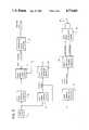
- FIG. 2A functional, schematic block diagram of the device 11 is shown in FIG. 2.
- a video clock 47generates a timed pulse which passes to pixel counter circuits 49 and to the CCD image sensor means 23.
- Output from the CCD image sensor means 23passes to video sample and hold circuits 57 and to peak amplitude detector circuits 55.
- Output from the video sample and hold circuits 57(peak video amplitude) pass to peak amplitude compare circuits 59.
- Output from the peak amplitude compare circuits 59(increase or decrease) pass to the laser drive modulator means 29 which in turn controls the laser diode 27.
- Output from the pixel counter circuits 49 and peak amplitude detector circuits 55pass to peak count latch circuits 51.
- the present inventionprovides a positioning measuring device having a high degree of repeatability (plus or minus 1/32 inch), having a small sense area (1/10 inch square) that can take up to 500 measurements per second that needs little or no calibration after initial calibration at installation, etc.
Landscapes
- Physics & Mathematics (AREA)
- Electromagnetism (AREA)
- Engineering & Computer Science (AREA)
- General Physics & Mathematics (AREA)
- Computer Networks & Wireless Communication (AREA)
- Radar, Positioning & Navigation (AREA)
- Remote Sensing (AREA)
- Length Measuring Devices By Optical Means (AREA)
- Measurement Of Optical Distance (AREA)
Abstract
Description
Claims (8)
Priority Applications (1)
| Application Number | Priority Date | Filing Date | Title |
|---|---|---|---|
| US07/032,399US4774403A (en) | 1987-03-30 | 1987-03-30 | Triangulation-type position measuring device |
Applications Claiming Priority (1)
| Application Number | Priority Date | Filing Date | Title |
|---|---|---|---|
| US07/032,399US4774403A (en) | 1987-03-30 | 1987-03-30 | Triangulation-type position measuring device |
Publications (1)
| Publication Number | Publication Date |
|---|---|
| US4774403Atrue US4774403A (en) | 1988-09-27 |
Family
ID=21864764
Family Applications (1)
| Application Number | Title | Priority Date | Filing Date |
|---|---|---|---|
| US07/032,399Expired - LifetimeUS4774403A (en) | 1987-03-30 | 1987-03-30 | Triangulation-type position measuring device |
Country Status (1)
| Country | Link |
|---|---|
| US (1) | US4774403A (en) |
Cited By (22)
| Publication number | Priority date | Publication date | Assignee | Title |
|---|---|---|---|---|
| US4929843A (en)* | 1989-06-28 | 1990-05-29 | General Electric Company | Apparatus and method for determining a dimension of an object |
| US4963731A (en)* | 1989-08-11 | 1990-10-16 | Courser, Incorporated | Optical level measurement system |
| US5028799A (en)* | 1988-08-01 | 1991-07-02 | Robotic Vision System, Inc. | Method and apparatus for three dimensional object surface determination using co-planar data from multiple sensors |
| US5056914A (en)* | 1990-07-12 | 1991-10-15 | Ball Corporation | Charge integration range detector |
| US5151608A (en)* | 1989-04-19 | 1992-09-29 | Fanuc Ltd | Optical distance sensor using a laser beam and processing means |
| US5187361A (en)* | 1989-04-25 | 1993-02-16 | Copal Company Limited | Object detection apparatus of the photoelectric reflection type with sampled data |
| US5477459A (en)* | 1992-03-06 | 1995-12-19 | Clegg; Philip M. | Real time three-dimensional machine locating system |
| EP0784214A2 (en) | 1996-01-09 | 1997-07-16 | Elop Electro-Optics Industries Ltd. | An optical tracing system |
| US5956134A (en)* | 1997-07-11 | 1999-09-21 | Semiconductor Technologies & Instruments, Inc. | Inspection system and method for leads of semiconductor devices |
| US5973770A (en)* | 1998-05-06 | 1999-10-26 | Quantum Imaging, Inc. | Method for measuring the relative proximity of and interacting with a plurality of media/molecular structures |
| US6118540A (en)* | 1997-07-11 | 2000-09-12 | Semiconductor Technologies & Instruments, Inc. | Method and apparatus for inspecting a workpiece |
| US6122039A (en)* | 1998-10-28 | 2000-09-19 | Banner Engineering Corp. | Method and apparatus to detect and report object displacement utilizing optical triangulation principles |
| US6259516B1 (en) | 1998-05-06 | 2001-07-10 | Quantum Imaging, Inc. | Dual sensor distance measuring apparatus and method |
| DE10049300C1 (en)* | 2000-10-04 | 2002-06-27 | Brand Gmbh & Co Kg | Appliance for metering out and titrating liquids has a container for liquids connected with its flow to an outlet element for liquids that opens and closes for dosing and titrating functions. |
| KR100421729B1 (en)* | 2000-08-25 | 2004-03-10 | 재단법인 포항산업과학연구원 | A laser triangulation sensor with multiple position detection rules |
| US20040085549A1 (en)* | 2000-12-29 | 2004-05-06 | Carl Smets | Method and an apparatus for measuring positions of contact elements of an electronic component |
| WO2005078416A1 (en)* | 2004-02-18 | 2005-08-25 | Innsitec Laser Technologies Gmbh | Device and method for determination of the chemical composition of solid liquid or gaseous materials |
| US20080279971A1 (en)* | 2007-05-11 | 2008-11-13 | Wilkerson Jeffry L | Tooling die parting line displacement sensor system |
| US20130256285A1 (en)* | 2012-03-30 | 2013-10-03 | View, Inc. | Coaxial distance measurement via folding of triangulation sensor optics path |
| US8715173B2 (en)* | 2012-03-12 | 2014-05-06 | United Sciences, Llc | Otoscanner with fan and ring laser |
| US8900126B2 (en) | 2011-03-23 | 2014-12-02 | United Sciences, Llc | Optical scanning device |
| US11210887B2 (en) | 2018-07-19 | 2021-12-28 | Crane Payment Innovations, Inc. | Multipurpose cashbag level and banknote presence in escrow detector |
Citations (3)
| Publication number | Priority date | Publication date | Assignee | Title |
|---|---|---|---|---|
| US4274735A (en)* | 1978-05-25 | 1981-06-23 | Canon Kabushiki Kaisha | Distance measuring device |
| US4527891A (en)* | 1982-08-18 | 1985-07-09 | Eastman Kodak Company | Rangefinder device with serial readout linear image sensor and peak detector with threshold setting means |
| US4567347A (en)* | 1983-12-15 | 1986-01-28 | Ntt Gijutsu Iten Kabushiki Kaisha | Measurement head for welding machines |
- 1987
- 1987-03-30USUS07/032,399patent/US4774403A/ennot_activeExpired - Lifetime
Patent Citations (3)
| Publication number | Priority date | Publication date | Assignee | Title |
|---|---|---|---|---|
| US4274735A (en)* | 1978-05-25 | 1981-06-23 | Canon Kabushiki Kaisha | Distance measuring device |
| US4527891A (en)* | 1982-08-18 | 1985-07-09 | Eastman Kodak Company | Rangefinder device with serial readout linear image sensor and peak detector with threshold setting means |
| US4567347A (en)* | 1983-12-15 | 1986-01-28 | Ntt Gijutsu Iten Kabushiki Kaisha | Measurement head for welding machines |
Cited By (30)
| Publication number | Priority date | Publication date | Assignee | Title |
|---|---|---|---|---|
| US5028799A (en)* | 1988-08-01 | 1991-07-02 | Robotic Vision System, Inc. | Method and apparatus for three dimensional object surface determination using co-planar data from multiple sensors |
| US5151608A (en)* | 1989-04-19 | 1992-09-29 | Fanuc Ltd | Optical distance sensor using a laser beam and processing means |
| US5187361A (en)* | 1989-04-25 | 1993-02-16 | Copal Company Limited | Object detection apparatus of the photoelectric reflection type with sampled data |
| US4929843A (en)* | 1989-06-28 | 1990-05-29 | General Electric Company | Apparatus and method for determining a dimension of an object |
| US4963731A (en)* | 1989-08-11 | 1990-10-16 | Courser, Incorporated | Optical level measurement system |
| US5056914A (en)* | 1990-07-12 | 1991-10-15 | Ball Corporation | Charge integration range detector |
| US5477459A (en)* | 1992-03-06 | 1995-12-19 | Clegg; Philip M. | Real time three-dimensional machine locating system |
| EP0784214A2 (en) | 1996-01-09 | 1997-07-16 | Elop Electro-Optics Industries Ltd. | An optical tracing system |
| US5956134A (en)* | 1997-07-11 | 1999-09-21 | Semiconductor Technologies & Instruments, Inc. | Inspection system and method for leads of semiconductor devices |
| US6118540A (en)* | 1997-07-11 | 2000-09-12 | Semiconductor Technologies & Instruments, Inc. | Method and apparatus for inspecting a workpiece |
| US5973770A (en)* | 1998-05-06 | 1999-10-26 | Quantum Imaging, Inc. | Method for measuring the relative proximity of and interacting with a plurality of media/molecular structures |
| US6259516B1 (en) | 1998-05-06 | 2001-07-10 | Quantum Imaging, Inc. | Dual sensor distance measuring apparatus and method |
| US6122039A (en)* | 1998-10-28 | 2000-09-19 | Banner Engineering Corp. | Method and apparatus to detect and report object displacement utilizing optical triangulation principles |
| KR100421729B1 (en)* | 2000-08-25 | 2004-03-10 | 재단법인 포항산업과학연구원 | A laser triangulation sensor with multiple position detection rules |
| DE10049300C1 (en)* | 2000-10-04 | 2002-06-27 | Brand Gmbh & Co Kg | Appliance for metering out and titrating liquids has a container for liquids connected with its flow to an outlet element for liquids that opens and closes for dosing and titrating functions. |
| US20040085549A1 (en)* | 2000-12-29 | 2004-05-06 | Carl Smets | Method and an apparatus for measuring positions of contact elements of an electronic component |
| US7423743B2 (en) | 2000-12-29 | 2008-09-09 | Icos Vision Systems Nv | Method and an apparatus for measuring positions of contact elements of an electronic component |
| WO2005078416A1 (en)* | 2004-02-18 | 2005-08-25 | Innsitec Laser Technologies Gmbh | Device and method for determination of the chemical composition of solid liquid or gaseous materials |
| US20080279971A1 (en)* | 2007-05-11 | 2008-11-13 | Wilkerson Jeffry L | Tooling die parting line displacement sensor system |
| US8900126B2 (en) | 2011-03-23 | 2014-12-02 | United Sciences, Llc | Optical scanning device |
| US8900129B2 (en) | 2012-03-12 | 2014-12-02 | United Sciences, Llc | Video otoscanner with line-of-sight probe and screen |
| US8900130B2 (en) | 2012-03-12 | 2014-12-02 | United Sciences, Llc | Otoscanner with safety warning system |
| US8715173B2 (en)* | 2012-03-12 | 2014-05-06 | United Sciences, Llc | Otoscanner with fan and ring laser |
| US8900127B2 (en) | 2012-03-12 | 2014-12-02 | United Sciences, Llc | Otoscanner with pressure sensor for compliance measurement |
| US8900125B2 (en) | 2012-03-12 | 2014-12-02 | United Sciences, Llc | Otoscanning with 3D modeling |
| US8900128B2 (en) | 2012-03-12 | 2014-12-02 | United Sciences, Llc | Otoscanner with camera for video and scanning |
| US20130256285A1 (en)* | 2012-03-30 | 2013-10-03 | View, Inc. | Coaxial distance measurement via folding of triangulation sensor optics path |
| US10112258B2 (en)* | 2012-03-30 | 2018-10-30 | View, Inc. | Coaxial distance measurement via folding of triangulation sensor optics path |
| US11210887B2 (en) | 2018-07-19 | 2021-12-28 | Crane Payment Innovations, Inc. | Multipurpose cashbag level and banknote presence in escrow detector |
| US11908264B2 (en) | 2018-07-19 | 2024-02-20 | Crane Payment Innovations, Inc. | Multipurpose cashbag level and banknote presence in escrow detector |
Similar Documents
| Publication | Publication Date | Title |
|---|---|---|
| US4774403A (en) | Triangulation-type position measuring device | |
| US4705395A (en) | Triangulation data integrity | |
| US6512575B1 (en) | Method and a device for measuring the distance of an object | |
| US4375921A (en) | Dimension measuring apparatus | |
| US4670659A (en) | Calibration method for an optical measuring system employing reference grids in a series of reference planes | |
| US6573981B2 (en) | Electronic level | |
| EP0148138B1 (en) | Method and apparatus for calibrating a positioning system | |
| US3536405A (en) | Optical thickness gauge | |
| US6314812B1 (en) | Apparatus and method for binocular measurement system | |
| US4604526A (en) | Position detector | |
| US4488813A (en) | Reflectivity compensating system for fiber optic sensor employing dual probes at a fixed gap differential | |
| US4762412A (en) | Optical scanning device | |
| US5347135A (en) | Method and apparatus employing a linear array IR region radiation devices for locating the position of conveyor transported products | |
| US4812043A (en) | Method for measuring a physical quantity providing digital data using analog-value measuring devices, and measuring apparatus for applying this method | |
| US6614537B1 (en) | Measuring apparatus and measuring method | |
| UST102104I4 (en) | Scanning optical system adapted for linewidth measurement in semiconductor devices | |
| US5030840A (en) | Analog laser receiver for determining the position of incidence of a beam of laser light thereon | |
| US4917488A (en) | Photocell distance measurement | |
| US5448361A (en) | Electro-optical micrometer | |
| CN115446333A (en) | Galvanometer Calibration Structure and Laser Calibration Method | |
| RU2091711C1 (en) | Process of range measurement and device for its realization | |
| US4704558A (en) | Method and apparatus for automatic oscilloscope calibration | |
| US20050279913A1 (en) | Target tracking device for a flight vehicle | |
| US4712914A (en) | Device for characterizing wide angle beams | |
| JPH0537230Y2 (en) |
Legal Events
| Date | Code | Title | Description |
|---|---|---|---|
| AS | Assignment | Owner name:HARVEY INDUSTRIES, INC., LITTLE ROCK, AK. A CORP. Free format text:ASSIGNMENT OF ASSIGNORS INTEREST.;ASSIGNOR:ARTS, MICHAEL T.;REEL/FRAME:004687/0431 Effective date:19870319 Owner name:HARVEY INDUSTRIES, INC.,ARKANSAS Free format text:ASSIGNMENT OF ASSIGNORS INTEREST;ASSIGNOR:ARTS, MICHAEL T.;REEL/FRAME:004687/0431 Effective date:19870319 | |
| STCF | Information on status: patent grant | Free format text:PATENTED CASE | |
| FPAY | Fee payment | Year of fee payment:4 | |
| AS | Assignment | Owner name:CONSOLIDATED SAWMILL MACHINERY INTERNATIONAL, INC. Free format text:ASSIGNMENT OF ASSIGNORS INTEREST;ASSIGNOR:HARVEY INDUSTRIES, INC.;REEL/FRAME:006616/0860 Effective date:19930624 Owner name:CONSOLIDATED SAWMILL MACHINERY INTERNATIONAL, INC. Free format text:CHANGE OF NAME;ASSIGNOR:HSC ACQUISITION, INC.;REEL/FRAME:006615/0052 Effective date:19930121 | |
| FEPP | Fee payment procedure | Free format text:PAYOR NUMBER ASSIGNED (ORIGINAL EVENT CODE: ASPN); ENTITY STATUS OF PATENT OWNER: LARGE ENTITY Free format text:PAT HLDR NO LONGER CLAIMS SMALL ENT STAT AS SMALL BUSINESS (ORIGINAL EVENT CODE: LSM2); ENTITY STATUS OF PATENT OWNER: LARGE ENTITY | |
| FPAY | Fee payment | Year of fee payment:8 | |
| FPAY | Fee payment | Year of fee payment:12 | |
| AS | Assignment | Owner name:U.S. NATURAL RESOURCES, WASHINGTON Free format text:MERGER;ASSIGNOR:CONSOLIDATED SAWMILL MACHINERY INTERNATIONAL;REEL/FRAME:014580/0553 Effective date:19960102 |