US4773478A - Hydraulic setting tool - Google Patents
Hydraulic setting toolDownload PDFInfo
- Publication number
- US4773478A US4773478AUS07/054,644US5464487AUS4773478AUS 4773478 AUS4773478 AUS 4773478AUS 5464487 AUS5464487 AUS 5464487AUS 4773478 AUS4773478 AUS 4773478A
- Authority
- US
- United States
- Prior art keywords
- piston
- setting tool
- hydraulic setting
- adapter
- housing
- Prior art date
- Legal status (The legal status is an assumption and is not a legal conclusion. Google has not performed a legal analysis and makes no representation as to the accuracy of the status listed.)
- Expired - Lifetime
Links
Images
Classifications
- E—FIXED CONSTRUCTIONS
- E21—EARTH OR ROCK DRILLING; MINING
- E21B—EARTH OR ROCK DRILLING; OBTAINING OIL, GAS, WATER, SOLUBLE OR MELTABLE MATERIALS OR A SLURRY OF MINERALS FROM WELLS
- E21B33/00—Sealing or packing boreholes or wells
- E21B33/10—Sealing or packing boreholes or wells in the borehole
- E21B33/12—Packers; Plugs
- E21B33/129—Packers; Plugs with mechanical slips for hooking into the casing
- E21B33/1295—Packers; Plugs with mechanical slips for hooking into the casing actuated by fluid pressure
- E—FIXED CONSTRUCTIONS
- E21—EARTH OR ROCK DRILLING; MINING
- E21B—EARTH OR ROCK DRILLING; OBTAINING OIL, GAS, WATER, SOLUBLE OR MELTABLE MATERIALS OR A SLURRY OF MINERALS FROM WELLS
- E21B23/00—Apparatus for displacing, setting, locking, releasing or removing tools, packers or the like in boreholes or wells
- E21B23/06—Apparatus for displacing, setting, locking, releasing or removing tools, packers or the like in boreholes or wells for setting packers
Definitions
- This inventionrelates to a hydraulic setting tool for packers and bridge plugs. More specifically, this invention relates to a hydraluic setting tool for a bridge plug for use in geothermal steam producing wells.
- Hydraulic setting tools for packers and bridge plugsare well known in the art. Some examples of prior art hydraulic setting tools for packers and bridge plugs are shown in U.S. Pat. Nos. 4,436,149, 4,441,552 and 4,516,634. However, such prior art hydraulic packer and bridge plug setting tools are either complex in construction and/or operation or require the use of balls or plugs to be pumped through the tubing string for the actuation of the setting tool in response to hydraulic fluid pressure in either the tubing string or annulus between the tubing string and well casing in which the packer or bridge plug is being set.
- a hydraulic setting toolwhich is simple in construction and actuation, does not allow steam from the well or well fluid to flow into the tubing string while the packer or bridge plug is being run into the well, does not require either rotational or longitudinal movement of the tubing work string or drill pipe to actuate the setting tool, and does not use balls or plugs to actuate the setting tool.
- the present inventionis directed to a hydraulic setting tool for packers and bridge plugs which is simple in construction and actuation, does not allow the flow of fluids into the tubing string upon which the setting tool and packer or bridge plug is being run into the well, does not require either rotational or longitudinal movement of the testing work string or drill pipe to actuate the setting tool, does not use balls or plugs to actuate the setting tool, and allows circulation of the well fluid after the packer or bridge plug is set.
- the hydraulic setting tool of the present inventioncomprises an adapter, housing, piston, piston sleeve and shear sleeve rod.
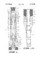
- FIG. 1is a cross-sectional view of the hydraulic setting tool of the present invention connected to the upper portion of a bridge plug.
- FIG. 1Ais a cross-sectional view of the remaining portion of the bridge plug shown in FIG. 1.
- the hydraulic setting tool 10 of the present inventionis shown in FIG. 1 in its preferred embodiment.
- the hydraulic setting tool 10comprises an adapter 12, housing 14, piston 16, piston sleeve 18 and shear sleeve rod 20. Also shown in FIG. 1 is the upper portion of a bridge plug 200 to which the hydraulic setting tool 10 is connected.
- the bridge plug 200is similar in construction and operation to the bridge plug described and shown in U.S. Pat. No. 4,185,689.
- the bridge plug 200 shown in FIG. 1has a flat annular surface 202 on upper slip support 204 for a portion of the hydraulic setting tool 10 to bear upon during actuation of the setting tool.
- the bridge plug 200also includes upper slips 208 and lock ring 203 contained within upper slip support 204.
- the adapter 12 of the hydraulic setting tool 10comprises a cylindrical annular member having, on the exterior thereof first cylindrical surface 22, second cylindrical surface 24 having annular recess 26 therein containing annular elastomeric seal means 28, threaded surface 30 and third cylindrical surface 32 and, on the interior thereof, threaded bore 34, first frusto-conical bore 35, first bore 36, second frusto-conical bore 37, second bore 38, frusto-conical surface 40, a plurality of axial passageways 42, threaded blind bore 43, and second bore 44.
- the adapter 12further includes a plurality of apertures 46 extending from third cylindrical surface 32 to second bore 44.
- the housing 14 of the hydraulic setting tool 10comprises an elongated annular cylindrical member having, on the exterior thereof, cylindrical surface 48 and, on the interior thereof, first cylindrical surface 50 which sealingly engages annular elastomeric seal means 28 of adapter 12, threaded bore 52 which releasably engages threaded surface 30 of adapter 12, first frusto-conical bore 54, second bore 56, second frusto-conical bore 58 and third bore 60.
- the piston 16 of the hydraulic setting tool 10comprises an annular cylindrical member having, on the exterior thereof, first cylindrical surface 62 having annular recess 64 therein, second cylindrical surface 66 having a plurality of recesses 68 therein containing annular elastomeric seal means 70 which slidingly, sealingly engage second bore 56 of housing 14 and threaded surface 72 and, on the interior thereof, bore 74 having a plurality of annular recesses 76 therein containing annular elastomeric seal means 78.
- the piston 16further includes a plurality of shear pins 79 having a portion thereof engaging apertures 46 of adapter 12 and a portion thereof extending into annular recess 74 of piston 16.
- the piston sleeve 18 of the hydraulic setting tool 10comprises an elongated annular cylindrical member having, on the exterior thereof, cylindrical surface 80 and, on the interior thereof, threaded bore 82 which releasably engages threaded surface 72 of piston 16 and bore 84.
- the shear sleeve rod 20 of the hydraulic setting tool 10comprises an elongated cylindrical member having threaded upper end 86, cylindrical surface 85 which slidingly, sealingly engages annular elastomeric seal means 78 of piston 16, annular flange 87 on the bottom end thereof, and blind threaded bore 89 therein.
- the shear sleeve rod 20further includes shear rod adapter end 91 having threaded end 93 which releasably engages blind threaded bore 89 of rod 20 and annular flange 88 thereon and shear sleeve adapter 90 which has one end thereof abutting annular flange 85 of rod 20 while the other end thereof abuts annular flange 88 of shear rod adapter end 91 and threaded exterior surface 92 which releasably engages shear sleeve 206 of bridge plug 200.
- the bridge plug 200includes upper slip wedge 210, packer element 212 lower slip wedge 214, slips 216, lower slip support 218, catcher assembly 220, push out plug assembly 222, and mandrel 224.
- the hydraulic setting tool 10is connected to a work string of tubing or drill pipe by adapter 12 threadedly engaging one end thereof.
- the bridge plug 200 or packeris retained upon the hydraulic setting tool 10 by shear sleeve rod 20 having shear sleeve adapter 90 threadedly engaging shear ring 206 of bridge plug 200.
- fluid pressure in the work string of tubing or drill pipeis increased until the fluid pressure acting on the upper end of piston 16 is great enough to cause the shear pins 79 to shear thereby allowing piston 16 having piston sleeve 18 connected thereto to move downwardly causing the lower end of the piston sleeve 18 to spread lock ring 203 outwardly so that sleeve 18 may pass therethrough to bear on flat annular surface 202 of upper slip support 204 of bridge plug 200.
- the piston 16 and piston sleeve 18continue to move downwardly causing upper slips 208 to be cammed into engagement with the casing (not shown) in the well bore.
- sand or gelled fluidcan then be placed on top of plug or the well can be circulated with fluid from the bridge plug up by pumping fluid through the tubing work string or drill pipe through passageways 42 in adapter 12, through the annulus between the housing 14 and shear sleeve rod 20, past piston 16 which is abutting annular flange 87 on shear sleeve rod 20 and out the annulus formed between third bore 60 of housing 14 and cylindrical surface 80 of piston 16 over the top of bridge plug 200 into the casing in the well bore.
- the construction of the hydraulic setting tool 10is simple, that the operation of the hydraulic setting tool 10 is simple, that fluid flow through the hydraulic setting tool 10 is prevented by the piston 16 and shear sleeve rod 20, that no balls or plugs are required to be pumped through the tubing work string or drill pipe to be able to actuate the hydraulic setting tool 10, and that no rotation or longitudinal movement of the tubing work string or drill pipe is required to actuate the hydraulic setting tool 10, and that the fluid in the annulus between the tubing work string or drill pipe and the casing in the well bore may be circulated out if desired.
Landscapes
- Life Sciences & Earth Sciences (AREA)
- Engineering & Computer Science (AREA)
- Geology (AREA)
- Mining & Mineral Resources (AREA)
- Physics & Mathematics (AREA)
- Environmental & Geological Engineering (AREA)
- Fluid Mechanics (AREA)
- General Life Sciences & Earth Sciences (AREA)
- Geochemistry & Mineralogy (AREA)
- Earth Drilling (AREA)
Abstract
Description
This invention relates to a hydraulic setting tool for packers and bridge plugs. More specifically, this invention relates to a hydraluic setting tool for a bridge plug for use in geothermal steam producing wells.
Hydraulic setting tools for packers and bridge plugs are well known in the art. Some examples of prior art hydraulic setting tools for packers and bridge plugs are shown in U.S. Pat. Nos. 4,436,149, 4,441,552 and 4,516,634. However, such prior art hydraulic packer and bridge plug setting tools are either complex in construction and/or operation or require the use of balls or plugs to be pumped through the tubing string for the actuation of the setting tool in response to hydraulic fluid pressure in either the tubing string or annulus between the tubing string and well casing in which the packer or bridge plug is being set.
In steam producing geothermal wells or in highly deviated wells it is desirable to have a hydraulic setting tool which is simple in construction and actuation, does not allow steam from the well or well fluid to flow into the tubing string while the packer or bridge plug is being run into the well, does not require either rotational or longitudinal movement of the tubing work string or drill pipe to actuate the setting tool, and does not use balls or plugs to actuate the setting tool.
The present invention is directed to a hydraulic setting tool for packers and bridge plugs which is simple in construction and actuation, does not allow the flow of fluids into the tubing string upon which the setting tool and packer or bridge plug is being run into the well, does not require either rotational or longitudinal movement of the testing work string or drill pipe to actuate the setting tool, does not use balls or plugs to actuate the setting tool, and allows circulation of the well fluid after the packer or bridge plug is set. The hydraulic setting tool of the present invention comprises an adapter, housing, piston, piston sleeve and shear sleeve rod.
FIG. 1 is a cross-sectional view of the hydraulic setting tool of the present invention connected to the upper portion of a bridge plug.
FIG. 1A is a cross-sectional view of the remaining portion of the bridge plug shown in FIG. 1.
Thehydraulic setting tool 10 of the present invention is shown in FIG. 1 in its preferred embodiment.
Thehydraulic setting tool 10 comprises anadapter 12,housing 14,piston 16,piston sleeve 18 andshear sleeve rod 20. Also shown in FIG. 1 is the upper portion of abridge plug 200 to which thehydraulic setting tool 10 is connected. Thebridge plug 200 is similar in construction and operation to the bridge plug described and shown in U.S. Pat. No. 4,185,689. Thebridge plug 200 shown in FIG. 1 has a flatannular surface 202 onupper slip support 204 for a portion of thehydraulic setting tool 10 to bear upon during actuation of the setting tool. Thebridge plug 200 also includesupper slips 208 andlock ring 203 contained withinupper slip support 204.
Theadapter 12 of thehydraulic setting tool 10 comprises a cylindrical annular member having, on the exterior thereof firstcylindrical surface 22, secondcylindrical surface 24 havingannular recess 26 therein containing annular elastomeric seal means 28, threadedsurface 30 and thirdcylindrical surface 32 and, on the interior thereof, threadedbore 34, first frusto-conical bore 35,first bore 36, second frusto-conical bore 37,second bore 38, frusto-conical surface 40, a plurality ofaxial passageways 42, threadedblind bore 43, andsecond bore 44. Theadapter 12 further includes a plurality ofapertures 46 extending from thirdcylindrical surface 32 tosecond bore 44.
Thehousing 14 of thehydraulic setting tool 10 comprises an elongated annular cylindrical member having, on the exterior thereof,cylindrical surface 48 and, on the interior thereof, firstcylindrical surface 50 which sealingly engages annular elastomeric seal means 28 ofadapter 12, threadedbore 52 which releasably engages threadedsurface 30 ofadapter 12, first frusto-conical bore 54,second bore 56, second frusto-conical bore 58 andthird bore 60.
Thepiston 16 of thehydraulic setting tool 10 comprises an annular cylindrical member having, on the exterior thereof, firstcylindrical surface 62 havingannular recess 64 therein, secondcylindrical surface 66 having a plurality ofrecesses 68 therein containing annular elastomeric seal means 70 which slidingly, sealingly engagesecond bore 56 ofhousing 14 and threadedsurface 72 and, on the interior thereof, bore 74 having a plurality ofannular recesses 76 therein containing annular elastomeric seal means 78. Thepiston 16 further includes a plurality ofshear pins 79 having a portion thereofengaging apertures 46 ofadapter 12 and a portion thereof extending intoannular recess 74 ofpiston 16.
Thepiston sleeve 18 of thehydraulic setting tool 10 comprises an elongated annular cylindrical member having, on the exterior thereof,cylindrical surface 80 and, on the interior thereof, threadedbore 82 which releasably engages threadedsurface 72 ofpiston 16 and bore 84.
Theshear sleeve rod 20 of thehydraulic setting tool 10 comprises an elongated cylindrical member having threadedupper end 86,cylindrical surface 85 which slidingly, sealingly engages annular elastomeric seal means 78 ofpiston 16,annular flange 87 on the bottom end thereof, and blind threadedbore 89 therein. Theshear sleeve rod 20 further includes shearrod adapter end 91 having threadedend 93 which releasably engages blind threadedbore 89 ofrod 20 andannular flange 88 thereon andshear sleeve adapter 90 which has one end thereof abuttingannular flange 85 ofrod 20 while the other end thereof abutsannular flange 88 of shearrod adapter end 91 and threadedexterior surface 92 which releasably engagesshear sleeve 206 ofbridge plug 200.
Referring to FIG. 1A, the remaining portion of thebridge plug 200 is shown. Thebridge plug 200 includesupper slip wedge 210,packer element 212lower slip wedge 214,slips 216,lower slip support 218,catcher assembly 220, push outplug assembly 222, andmandrel 224.
Referring again to FIG. 1, the operation of thehydraulic setting tool 10 of the present invention will be set forth.
Thehydraulic setting tool 10 is connected to a work string of tubing or drill pipe byadapter 12 threadedly engaging one end thereof. Thebridge plug 200 or packer is retained upon thehydraulic setting tool 10 by shearsleeve rod 20 havingshear sleeve adapter 90 threadedly engagingshear ring 206 ofbridge plug 200.
After thehydraulic setting tool 10 havingbridge plug 200 connected thereto is assembled on the work string of tubing or drill pipe, thehydraulic setting tool 10 andbridge plug 200 are run into the well to the desired location at which the bridge plug is to be set.
To actuate thehydraulic setting tool 10 fluid pressure in the work string of tubing or drill pipe is increased until the fluid pressure acting on the upper end ofpiston 16 is great enough to cause theshear pins 79 to shear thereby allowingpiston 16 havingpiston sleeve 18 connected thereto to move downwardly causing the lower end of thepiston sleeve 18 to spreadlock ring 203 outwardly so thatsleeve 18 may pass therethrough to bear on flatannular surface 202 ofupper slip support 204 ofbridge plug 200. Thepiston 16 andpiston sleeve 18 continue to move downwardly causingupper slips 208 to be cammed into engagement with the casing (not shown) in the well bore.
When theupper slips 208 engage the casing in the well bore, further downward movement of theupper slips 208 is prevented. After theslips 208 engage the casing in the well bore, the relative movement between thepiston 16 andadapter 12 havinghousing 14 andshear rod 20 secured thereto occurs because the increased fluid pressure causes the force acting upwardly onadapter 12,housing 14 andshear sleeve rod 20 to be greater than the force acting downwardly onshear sleeve rod 20. At this point, the downward movement ofpiston 16 andpiston sleeve 18 generally ceases and theshear sleeve rod 20 moves upwardly relative to thepiston 16 andpiston sleeve 18 until the force acting onshear sleeve 206 of bridge plug viashear sleeve rod 20 causes theshear sleeve 206 to shear thereby releasing theshear sleeve rod 20 from theshear sleeve 206 andbridge plug 200. During the relative upward movement of theshear sleeve rod 20, since theshear sleeve 206 of thebridge plug 200 is attached to themandrel 224 of the bridge plug which, in turn, is attached tolower slip suport 218 of thebridge plug 200, thelower slips 216 are brought into engagement with the casing in the well which thereby prevents any further upward movement of theshear ring rod 20 until theshear ring 206 shears thereby releasingrod 20. At this point, thebridge plug 200 is set in the casing in the well and the hydraulic setting tool is released therefrom when sleeve 206 shears.
At this time, sand or gelled fluid can then be placed on top of plug or the well can be circulated with fluid from the bridge plug up by pumping fluid through the tubing work string or drill pipe throughpassageways 42 inadapter 12, through the annulus between thehousing 14 andshear sleeve rod 20,past piston 16 which is abuttingannular flange 87 onshear sleeve rod 20 and out the annulus formed betweenthird bore 60 ofhousing 14 andcylindrical surface 80 ofpiston 16 over the top of bridge plug 200 into the casing in the well bore.
Thus, it can be seen from the foregoing that the construction of thehydraulic setting tool 10 is simple, that the operation of thehydraulic setting tool 10 is simple, that fluid flow through thehydraulic setting tool 10 is prevented by thepiston 16 andshear sleeve rod 20, that no balls or plugs are required to be pumped through the tubing work string or drill pipe to be able to actuate thehydraulic setting tool 10, and that no rotation or longitudinal movement of the tubing work string or drill pipe is required to actuate thehydraulic setting tool 10, and that the fluid in the annulus between the tubing work string or drill pipe and the casing in the well bore may be circulated out if desired.
Claims (12)
1. A hydraulic setting tool attached to one end of a conduit string conveyed into a well, said hydraulic setting tool having a portion thereof attached to a packer conveyed into said well by said conduit string, said hydraulic setting tool comprising:
an adapter having a portion thereof secured to said conduit string;
a housing having a portion thereof secured to said adapter;
a piston having a portion thereof slidably sealingly engaging a portion of said housing;
a releasable retaining means retaining said piston in a first position within said housing, said releasable retaining means having a portion thereof engaging said housing and another portion thereof engaging said piston;
a piston sleeve having a portion thereof secured to said piston and slidable within said housing; and
a shear sleeve rod having one end thereof attached to a portion of said adapter and the other end thereof attached to a portion of said packer, said shear sleeve rod slidably, sealingly engaging a portion of said piston.
2. The hydraulic setting tool of claim 1 wherein said shear sleeve rod comprises:
an elongated cylindrical rod having an annular flange thereon; and
a shear sleeve adapter retained in one direction on the elongated cylindrical rod by the annular flange thereon.
3. The hydraulic setting tool of claim 1 wherein said releasable retaining means further comprises:
at least one shear pin extending between said adapter and said piston for releasably retaining said piston in a first position in said hydraulic setting tool.
4. The hydraulic setting tool of claim 1 wherein said piston includes:
exterior annular elastomeric seals on the exterior of said piston for slidably sealingly engaging a portion of said housing; and
interior annular elastomeric seals on the interior of said piston for slidably sealingly engaging a portion of said shear sleeve rod.
5. The hydraulic setting tool of claim 1 wherein said adapter further includes:
at least one axial passageway extending therethrough to allow fluid flow from said conduit string to said piston.
6. The hydraulic setting tool of claim 1 further comprising:
an annular elastomeric seal sealing between said adapter and said housing.
7. A hydraulic setting tool attached to one end of a conduit string conveyed into a well, said hydraulic setting tool having a portion thereof attached to a bridge plug conveyed into said well by said conduit string, said hydraulic setting tool comprising:
an adapter having a portion thereof secured to said conduit string;
a housing having a portion thereof securd to said adapter;
a piston having a portion thereof slidably sealingly engaging a portion of said housing;
a releasable retaining means retaining said piston in a first position within said housing, said releasable retaining means having a portion thereof engaging said housing and another portion thereof engaging said piston;
a piston sleeve having a portion thereof secured to said piston and slidable within said housing; and
a shear sleeve rod having one end thereof attached to a portion of said adapter and the other end thereof attached to a portion of said bridge plug, said shear sleeve rod slidably, sealingly engaging a portion of said piston.
8. The hydraulic setting tool of claim 7 wherein said shear sleeve rod comprises:
an elongated cylindrical rod having an annular flange thereon; and
a shear sleeve adapter retained in one direction on the elongated cylindrical rod by the annular flange thereon.
9. The hydraulic setting tool of claim 7 wherein said releasable retaining means further comprises:
at least one shear pin extending between said adapter and said piston for releasably retaining said piston in a first position in said hydraulic setting tool.
10. The hydraulic setting tool of claim 7 wherein said piston includes:
exterior annular elastomeric seals on the exterior of said piston for slidably sealingly engaging a portion of said housing; and
interior annular elastomeric seals on the interior of said piston for slidably sealingly engaging a portion of said shear sleeve rod.
11. The hydraulic setting tool of claim 7 wherein said adapter further includes:
at least one axial passageway extending therethrough to allow fluid flow from said conduit string to said piston.
12. The hydraulic setting tool of claim 7 further comprising:
an annular elastomeric seal sealing between said adapter and said housing.
Priority Applications (1)
| Application Number | Priority Date | Filing Date | Title |
|---|---|---|---|
| US07/054,644US4773478A (en) | 1987-05-27 | 1987-05-27 | Hydraulic setting tool |
Applications Claiming Priority (1)
| Application Number | Priority Date | Filing Date | Title |
|---|---|---|---|
| US07/054,644US4773478A (en) | 1987-05-27 | 1987-05-27 | Hydraulic setting tool |
Publications (1)
| Publication Number | Publication Date |
|---|---|
| US4773478Atrue US4773478A (en) | 1988-09-27 |
Family
ID=21992532
Family Applications (1)
| Application Number | Title | Priority Date | Filing Date |
|---|---|---|---|
| US07/054,644Expired - LifetimeUS4773478A (en) | 1987-05-27 | 1987-05-27 | Hydraulic setting tool |
Country Status (1)
| Country | Link |
|---|---|
| US (1) | US4773478A (en) |
Cited By (16)
| Publication number | Priority date | Publication date | Assignee | Title |
|---|---|---|---|---|
| US5152340A (en)* | 1991-01-30 | 1992-10-06 | Halliburton Company | Hydraulic set packer and testing apparatus |
| WO1994018429A1 (en)* | 1993-02-01 | 1994-08-18 | Magne Petter Nilsen | Sealing device for sealing of holes in the wall of a pipe in a curved oil well, an anchoring device for the sealing device and a tool for mounting of the sealing device and the anchoring device |
| US5404956A (en)* | 1993-05-07 | 1995-04-11 | Halliburton Company | Hydraulic setting tool and method of use |
| US5458196A (en)* | 1994-08-31 | 1995-10-17 | Halliburton Company | Through tubing gun hanger |
| US6257331B1 (en)* | 1999-07-28 | 2001-07-10 | Atlantic Richfield Company | Downhole setting tool |
| US6315044B1 (en) | 1998-11-12 | 2001-11-13 | Donald W. Tinker | Pre-milled window for drill casing |
| WO2003087530A1 (en)* | 2002-04-04 | 2003-10-23 | Weatherford/Lamb, Inc. | Releasing mechanism for downhole sealing tool |
| US20050056417A1 (en)* | 2003-09-11 | 2005-03-17 | Porter Jesse C. | Hydraulic setting tool for packers |
| US20050167094A1 (en)* | 2004-01-30 | 2005-08-04 | Streich Steven G. | System and method for sensing load on a downhole tool |
| US9169704B2 (en) | 2013-01-31 | 2015-10-27 | Halliburton Energy Services, Inc. | Expandable wedge slip for anchoring downhole tools |
| CN106499361A (en)* | 2016-12-13 | 2017-03-15 | 中国石油集团西部钻探工程有限公司 | Electric-controlled hydraulic automatic setting bridging device |
| US10920526B2 (en) | 2017-06-07 | 2021-02-16 | Halliburton Energy Services, Inc. | Downhole interventionless tools, systems, and methods for setting packers |
| WO2021032642A1 (en) | 2019-08-22 | 2021-02-25 | Interwell Norway As | Well tool device |
| US11199064B2 (en) | 2018-10-31 | 2021-12-14 | Halliburton Energy Services, Inc. | Integrated debris catcher and plug system |
| CN115075743A (en)* | 2022-06-23 | 2022-09-20 | 中海石油(中国)有限公司 | Bridge plug setting releasing adapter and matched tool and using method thereof |
| CN119434893A (en)* | 2020-09-14 | 2025-02-14 | 南通大学 | A bridge plug valveless hydraulic setting tool |
Citations (14)
| Publication number | Priority date | Publication date | Assignee | Title |
|---|---|---|---|---|
| US2467801A (en)* | 1946-10-26 | 1949-04-19 | Baker Oil Tools Inc | Hydraulically set well packer |
| US2624412A (en)* | 1949-02-25 | 1953-01-06 | Baker Oil Tools Inc | Hydraulic booster operated well packer |
| US2630865A (en)* | 1949-02-25 | 1953-03-10 | Baker Oil Tools Inc | Hydraulically operated well packer |
| US2687775A (en)* | 1950-07-10 | 1954-08-31 | Baker Oil Tools Inc | Setting tool and well packer |
| US4096913A (en)* | 1977-01-10 | 1978-06-27 | Baker International Corporation | Hydraulically set liner hanger and running tool with backup mechanical setting means |
| US4185689A (en)* | 1978-09-05 | 1980-01-29 | Halliburton Company | Casing bridge plug with push-out pressure equalizer valve |
| US4373584A (en)* | 1979-05-07 | 1983-02-15 | Baker International Corporation | Single trip tubing hanger assembly |
| US4436149A (en)* | 1982-06-18 | 1984-03-13 | Halliburton Company | Hydraulic setting tool |
| US4438811A (en)* | 1982-08-16 | 1984-03-27 | Otid Engineering Corporation | Latch for use in a well |
| US4441552A (en)* | 1982-06-18 | 1984-04-10 | Halliburton Company | Hydraulic setting tool with flapper valve |
| US4493374A (en)* | 1983-03-24 | 1985-01-15 | Arlington Automatics, Inc. | Hydraulic setting tool |
| US4516634A (en)* | 1983-04-14 | 1985-05-14 | Otis Engineering Corporation | Hydraulic running and setting tool for well packer |
| US4564068A (en)* | 1983-11-22 | 1986-01-14 | Smith International, Inc. | Emergency release for subsea tool |
| US4688634A (en)* | 1986-01-31 | 1987-08-25 | Dresser Industries, Inc. | Running and setting tool for well packers |
- 1987
- 1987-05-27USUS07/054,644patent/US4773478A/ennot_activeExpired - Lifetime
Patent Citations (14)
| Publication number | Priority date | Publication date | Assignee | Title |
|---|---|---|---|---|
| US2467801A (en)* | 1946-10-26 | 1949-04-19 | Baker Oil Tools Inc | Hydraulically set well packer |
| US2624412A (en)* | 1949-02-25 | 1953-01-06 | Baker Oil Tools Inc | Hydraulic booster operated well packer |
| US2630865A (en)* | 1949-02-25 | 1953-03-10 | Baker Oil Tools Inc | Hydraulically operated well packer |
| US2687775A (en)* | 1950-07-10 | 1954-08-31 | Baker Oil Tools Inc | Setting tool and well packer |
| US4096913A (en)* | 1977-01-10 | 1978-06-27 | Baker International Corporation | Hydraulically set liner hanger and running tool with backup mechanical setting means |
| US4185689A (en)* | 1978-09-05 | 1980-01-29 | Halliburton Company | Casing bridge plug with push-out pressure equalizer valve |
| US4373584A (en)* | 1979-05-07 | 1983-02-15 | Baker International Corporation | Single trip tubing hanger assembly |
| US4436149A (en)* | 1982-06-18 | 1984-03-13 | Halliburton Company | Hydraulic setting tool |
| US4441552A (en)* | 1982-06-18 | 1984-04-10 | Halliburton Company | Hydraulic setting tool with flapper valve |
| US4438811A (en)* | 1982-08-16 | 1984-03-27 | Otid Engineering Corporation | Latch for use in a well |
| US4493374A (en)* | 1983-03-24 | 1985-01-15 | Arlington Automatics, Inc. | Hydraulic setting tool |
| US4516634A (en)* | 1983-04-14 | 1985-05-14 | Otis Engineering Corporation | Hydraulic running and setting tool for well packer |
| US4564068A (en)* | 1983-11-22 | 1986-01-14 | Smith International, Inc. | Emergency release for subsea tool |
| US4688634A (en)* | 1986-01-31 | 1987-08-25 | Dresser Industries, Inc. | Running and setting tool for well packers |
Cited By (20)
| Publication number | Priority date | Publication date | Assignee | Title |
|---|---|---|---|---|
| US5152340A (en)* | 1991-01-30 | 1992-10-06 | Halliburton Company | Hydraulic set packer and testing apparatus |
| WO1994018429A1 (en)* | 1993-02-01 | 1994-08-18 | Magne Petter Nilsen | Sealing device for sealing of holes in the wall of a pipe in a curved oil well, an anchoring device for the sealing device and a tool for mounting of the sealing device and the anchoring device |
| US5404956A (en)* | 1993-05-07 | 1995-04-11 | Halliburton Company | Hydraulic setting tool and method of use |
| US5458196A (en)* | 1994-08-31 | 1995-10-17 | Halliburton Company | Through tubing gun hanger |
| US6315044B1 (en) | 1998-11-12 | 2001-11-13 | Donald W. Tinker | Pre-milled window for drill casing |
| US6257331B1 (en)* | 1999-07-28 | 2001-07-10 | Atlantic Richfield Company | Downhole setting tool |
| WO2003087530A1 (en)* | 2002-04-04 | 2003-10-23 | Weatherford/Lamb, Inc. | Releasing mechanism for downhole sealing tool |
| US6997252B2 (en) | 2003-09-11 | 2006-02-14 | Halliburton Energy Services, Inc. | Hydraulic setting tool for packers |
| US20050056417A1 (en)* | 2003-09-11 | 2005-03-17 | Porter Jesse C. | Hydraulic setting tool for packers |
| US7234517B2 (en) | 2004-01-30 | 2007-06-26 | Halliburton Energy Services, Inc. | System and method for sensing load on a downhole tool |
| US20050167094A1 (en)* | 2004-01-30 | 2005-08-04 | Streich Steven G. | System and method for sensing load on a downhole tool |
| US9169704B2 (en) | 2013-01-31 | 2015-10-27 | Halliburton Energy Services, Inc. | Expandable wedge slip for anchoring downhole tools |
| CN106499361A (en)* | 2016-12-13 | 2017-03-15 | 中国石油集团西部钻探工程有限公司 | Electric-controlled hydraulic automatic setting bridging device |
| CN106499361B (en)* | 2016-12-13 | 2023-03-14 | 中国石油天然气集团有限公司 | Electric control hydraulic automatic setting bridge plug device |
| US10920526B2 (en) | 2017-06-07 | 2021-02-16 | Halliburton Energy Services, Inc. | Downhole interventionless tools, systems, and methods for setting packers |
| US11199064B2 (en) | 2018-10-31 | 2021-12-14 | Halliburton Energy Services, Inc. | Integrated debris catcher and plug system |
| WO2021032642A1 (en) | 2019-08-22 | 2021-02-25 | Interwell Norway As | Well tool device |
| US12037872B2 (en) | 2019-08-22 | 2024-07-16 | Interwell Norway As | Well tool device |
| CN119434893A (en)* | 2020-09-14 | 2025-02-14 | 南通大学 | A bridge plug valveless hydraulic setting tool |
| CN115075743A (en)* | 2022-06-23 | 2022-09-20 | 中海石油(中国)有限公司 | Bridge plug setting releasing adapter and matched tool and using method thereof |
Similar Documents
| Publication | Publication Date | Title |
|---|---|---|
| US4773478A (en) | Hydraulic setting tool | |
| US4393931A (en) | Combination hydraulically set hanger assembly with expansion joint | |
| US3957114A (en) | Well treating method using an indexing automatic fill-up float valve | |
| US4105069A (en) | Gravel pack liner assembly and selective opening sleeve positioner assembly for use therewith | |
| EP1172521B1 (en) | Downhole packer with caged ball valve | |
| US5303772A (en) | Well completion apparatus | |
| US6802372B2 (en) | Apparatus for releasing a ball into a wellbore | |
| EP0477452B1 (en) | Downhole force generator | |
| US4258792A (en) | Hydraulic tubing tensioner | |
| US5411095A (en) | Apparatus for cementing a casing string | |
| US4224987A (en) | Well tool | |
| US4552218A (en) | Unloading injection control valve | |
| US4862966A (en) | Liner hanger with collapsible ball valve seat | |
| US4487258A (en) | Hydraulically set well packer | |
| US5372201A (en) | Annulus pressure actuated casing hanger running tool | |
| EP0853185A2 (en) | Inflation packer tool and method for well cementing | |
| US5261492A (en) | Well casing apparatus and method | |
| EP0697496A2 (en) | High pressure well cementing plug assembly | |
| EP0097457A2 (en) | Apparatus for setting a well tool in a well bore | |
| EP0233750A2 (en) | Bar vent for downhole tool | |
| CN111119747B (en) | Drilling string and drilling completion integrated method | |
| US3530948A (en) | Perforator | |
| US3139140A (en) | Hydrostatic pressure-actuatable nonretrievable packer | |
| US4687063A (en) | Well cementing method and apparatus | |
| US4018275A (en) | Anchoring device for well tools |
Legal Events
| Date | Code | Title | Description |
|---|---|---|---|
| AS | Assignment | Owner name:HALLIBURTON COMPANY, DUNCAN, STEPHENS COUNTY, OKLA Free format text:ASSIGNMENT OF ASSIGNORS INTEREST.;ASSIGNOR:STREICH, STEVEN G.;REEL/FRAME:004828/0562 Effective date:19880301 Owner name:HALLIBURTON COMPANY, A DE. CORP.,OKLAHOMA Free format text:ASSIGNMENT OF ASSIGNORS INTEREST;ASSIGNOR:STREICH, STEVEN G.;REEL/FRAME:004828/0562 Effective date:19880301 | |
| STCF | Information on status: patent grant | Free format text:PATENTED CASE | |
| FEPP | Fee payment procedure | Free format text:PAYOR NUMBER ASSIGNED (ORIGINAL EVENT CODE: ASPN); ENTITY STATUS OF PATENT OWNER: LARGE ENTITY | |
| FPAY | Fee payment | Year of fee payment:4 | |
| FPAY | Fee payment | Year of fee payment:8 | |
| FPAY | Fee payment | Year of fee payment:12 |