US4773164A - Self-aligning caliber bar - Google Patents
Self-aligning caliber barDownload PDFInfo
- Publication number
- US4773164A US4773164AUS07/059,069US5906987AUS4773164AUS 4773164 AUS4773164 AUS 4773164AUS 5906987 AUS5906987 AUS 5906987AUS 4773164 AUS4773164 AUS 4773164A
- Authority
- US
- United States
- Prior art keywords
- set forth
- series
- frame
- caliber
- centering arms
- Prior art date
- Legal status (The legal status is an assumption and is not a legal conclusion. Google has not performed a legal analysis and makes no representation as to the accuracy of the status listed.)
- Expired - Lifetime
Links
Images

Classifications
- F—MECHANICAL ENGINEERING; LIGHTING; HEATING; WEAPONS; BLASTING
- F41—WEAPONS
- F41G—WEAPON SIGHTS; AIMING
- F41G1/00—Sighting devices
- F41G1/54—Devices for testing or checking ; Tools for adjustment of sights
Definitions
- the present inventionrelates to an improved caliber bar for determining the longitudinal centerline of the bore at the muzzle end of a gun.
- the bore at the muzzle end of a gunmay be distorted so that its centerline no longer coincides with the alignment of the sights associated therewith.
- several test roundsare fired at a target and the sights are adjusted to coincide with the line of fire.
- various mechanical and/or optical deviceshave been developed for determining the centerline of the bore at the muzzle end of the gun. Some of these devices determine the bore centerline by direct measurement, others use indirect measuring means often determining a line parallel but not coaxial with the gun bore centerline. Devices, such as shown in U.S. Pat. No. 4,459,757, did not determine the centerline with accuracy within a short enough time period to be of use in the field.
- Another object of the present inventionis to provide an improved caliber bar which can be operated by unspecialized personnel in the field with high accuracy and reliability.
- Still another object of the present inventionis to provide a caliber bar which inherently can be used to find the centerline of bores of various diameters without requiring any adjustment or replacement of parts whatsoever.
- a further object of the present inventionis to provide an improved caliber bar utilizing liquid springs which will force centering arms against the sides of the bore with sufficient pressure to maintain the caliber bar firmly in place during the alignment procedure.
- Still another object of the present inventionis to provide an improved caliber bar utilizing liquid springs for biasing centering arms, the liquid springs being capable of providing high spring forces in the relatively small area in which the caliber bar is used.
- the present inventionrelates to a caliber bar for locating the centerline of the bore at the muzzle of a gun comprising a frame having a longitudinal axis, a first series of first arms spaced circumferentially from each other and movably mounted on said frame, a second series of second arms spaced circumferentially from each other and movably mounted on said frame, said first series of first arms being axially spaced from said second series of second arms, and biasing means for simultaneously biasing said first arms outwardly equal amounts from said longitudinal axis of said frame for engaging the side of said bore at a first location and for simultaneously biasing said second arms outwardly equal amounts from said longitudinal axis of said frame for engaging the side of said bore at a second location which is axially spaced from said first location to thereby cause said longitudinal axis of said frame to coincide with said centerline of said bore at the muzzle of said gun.
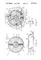
- FIG. 1is a plan view of the improved caliber bar of the present invention
- FIG. 2is a cross sectional view of the caliber bar taken substantially along line 2--2 of FIG. 1 and showing the caliber bar in the bore at the muzzle end of a gun;
- FIG. 3is a cross sectional view taken substantially along line 3--3 of FIG. 2;
- FIG. 4is a cross sectional view taken substantially along line 4--4 of FIG. 2 and showing the plug mounted in the remainder of the base within the frame;
- FIG. 5is a cross sectional view taken substantially along line 5--5 of FIG. 2 and showing the trunnion mountings for the centering arms;
- FIG. 6is a side elevational view of a centering arm
- FIG. 7is an end view of the centering arm taken from the right of FIG. 6.
- the improved caliber bar 10includes a frame or outer housing 11 in which trunnion housings or bases 12 and 13 are mounted. Trunnion housings 12 and 13 are identical in all respects except that housing 13 includes a threaded bushing 14 mounted in end wall 15 thereof. The threaded end 17 of rod 19 is screwed into bushing 14.
- Rod 19includes an enlarged portion 20 having an annular shoulder 21 which bears against washer 22 so that housing 23 bears against flange 24 of frame 11 when threaded end 17 is screwed into bushing 14.
- An optical collimator 25,which provides a reticle image (not shown) of the view along the centerline of rod 19, with overlaid grid, usually including cross hairs, is mounted at the end of rod portion 20.
- Rod 19is coaxial with the longitudinal centerline 27a of frame 11.
- trunnion housings 12 and 13are identical except for the above described difference. Therefore unprimed numerals will be used to designate the various parts of housing 13, and primed corresponding numerals will be used to designate corresponding parts of housing 12, thereby obviating the necessity for redundant descriptions.
- Trunnion housing 13includes a central portion 27 having three slots 29 (FIGS. 2 and 5) extending longitudinally thereof and circumferentially spaced 120° from each other.
- An end plate 15is located at the end of central portion 27, and as noted above, end plate 15 differs in the above-described manner from end plate 15' of housing 12.
- a base 30is located at the opposite end of central portion 27 from end plate 15.
- Base 30is of generally circular cross section (FIG. 5) except that it has cutouts 31 therein.
- Base 30also includes longitudinally extending slots 32 which are continuations of slots 29.
- Spring detent 28includes a housing (not numbered) which is screwed into base 30, and it includes a spring biased plunger 36 which is received in a mating aperture in frame 11, thereby removably holding trunnion housing 13 in position.
- a plurality of centering arms 33have first ends 34 having bores 35 therein (FIG. 6) which receive axle pins 37 when the ends of centering arms 33 are mounted in trunnion relationship in slots 32 of base 30.
- Axle pins 37have ends 39 which are received in associated bores 40 of base 30, with the central portions of axle pins 37 being received in bores 35 of the centering arms.
- the opposite ends of axle pins 37are received in bores 56.
- Set screws 41hold axle pins 37 in position.
- the ends of axle pins 37 proximate set screws 41are internally threaded to receive threaded puller members (not shown) used to pull pins 37 out of their associated bores.
- Each of the arms 33include a longitudinal rib 38 and a broad outer surface 46.
- Trunnion housing 13includes a bore 42 which receives the cylinder 43 of liquid spring 44 in slidable engagement, with the centerline of bore 42 and cylinder 43 being coaxial with centerline 27a of frame 11.
- Piston 45 of liquid spring 44includes a threaded extension 47 which is threaded into plug 49 which forms a part of base 30.
- Plug 49is held in base 30 by set screws 50 which are backed up by additional set screws 51.
- An annular collar 52is formed integrally with housing 43 so that it provides an annular shoulder 53 which abuts annular shoulder 54 (FIG. 2) of base 30 to define the limit of movement to the right of cylinder 43.
- a finger 55is located at the end of centering arm 33 and it has a surface 57 (FIG. 6) which bears against annular shoulder 53.
- liquid spring 44will bias all three fingers 33 outwardly simultaneously equal amounts in a counterclockwise direction in FIG. 2 when collar 52 is not abutting shoulder 54.
- the bore 59 at the muzzle end 60 of a gunwill be enlarged with use. This enlargement may be a regular or irregular belling out or it may constitute other types of distortions which cause the centerline of the bore to have an alignment which departs from the original centerline. Furthermore, the path of the projectile will follow the centerline of the portion of the muzzle end of the bore which has a length roughly four to five times the nominal diameter of the bore. For example, if the bore is 105 millimeter, the projectile will follow a path which is determined by the longitudinal axis of four to five times 105 millimeter at the muzzle end of the bore.
- the improved caliber bar 10 of the present inventionallows precise alignment of the optical sight on the gun (not shown) with the centerline of the muzzle end of the barrel, with the projected centerline being visually observed through optical collimator 25.
- the three sets of centering arms 33will automatically find the center of the portion of the bore where their ends 61 of surfaces 46 contact the adjacent portions of bore 59.
- the ends 61' of centering arms 33'will also determine the center at the portions of bore 59 which they contact. It will be noted that both sets of arms 33 and 33' contact the muzzle end of the bore at locations spaced axially inwardly from the very end of the muzzle to thus accurately determine the bore centerline, because the very end of the muzzle cannot be used as a reference point for accurately determining the bore centerline.
- Centering arms 33extend through slots 63 in frame 11 so that they can move back and forth about the axes of pins 37, as required.
- the ends 48 of arms 33will abut the inner surface of frame 11 to further limit the counterclockwise rotation of arms 33 after shoulder 53 abuts shoulder 54.
- centering arms 33will be biased simultaneously equal amounts in a counterclockwise direction because of the interengagement between fingers 55 and collar 52.
- centering arms 33'which may be biased outwardly equal amounts which may be different than those of arms 33.
- the centerlines of cylinders 43 and 43' and the centerline of frame 11will coincide with the centerline of the portion of muzzle bore 59 which is contacted by the outer curved ends 61 of centering arms 33 and 33'.
- the collimator 25is aligned with the centerline of frame 11, and thus will be aligned with the centerline of bore 59.
- the centerline of the bore at the muzzle end of the gunwill be in line with the target, and then the sights (not shown) on the gun can also be adjusted to be aligned with the target with any known variance between the bore centerline and the line of fire being taken into account, and thus the gun sights will be properly correlated with the centerline of the bore at the muzzle end of the gun.
- the contacting ends 61 and 61' of centering arms 33 and 33'are curved (FIG. 5) so as to make substantial point contact with bore 59.
- the collimator 25is a well known device, by way of broad description, it includes optics which essentially include a prism and lens structure so that when the end 25a is pointed at a target, the latter will be visible to a viewer looking down at surface 25b, and the target will appear on a suitable grid work or cross hairs at surface 25b.
- the muzzle 60has its centerline 27a pointed directly at the target, the latter will be centered directly on the cross hairs.
Landscapes
- Physics & Mathematics (AREA)
- Optics & Photonics (AREA)
- Engineering & Computer Science (AREA)
- General Engineering & Computer Science (AREA)
- Conveying And Assembling Of Building Elements In Situ (AREA)
Abstract
Description
Claims (20)
Priority Applications (1)
| Application Number | Priority Date | Filing Date | Title |
|---|---|---|---|
| US07/059,069US4773164A (en) | 1987-06-08 | 1987-06-08 | Self-aligning caliber bar |
Applications Claiming Priority (1)
| Application Number | Priority Date | Filing Date | Title |
|---|---|---|---|
| US07/059,069US4773164A (en) | 1987-06-08 | 1987-06-08 | Self-aligning caliber bar |
Publications (1)
| Publication Number | Publication Date |
|---|---|
| US4773164Atrue US4773164A (en) | 1988-09-27 |
Family
ID=22020650
Family Applications (1)
| Application Number | Title | Priority Date | Filing Date |
|---|---|---|---|
| US07/059,069Expired - LifetimeUS4773164A (en) | 1987-06-08 | 1987-06-08 | Self-aligning caliber bar |
Country Status (1)
| Country | Link |
|---|---|
| US (1) | US4773164A (en) |
Cited By (24)
| Publication number | Priority date | Publication date | Assignee | Title |
|---|---|---|---|---|
| US5377421A (en)* | 1993-04-30 | 1995-01-03 | Isler; David | Centering tool for cylinder gauge |
| US5379522A (en)* | 1991-12-04 | 1995-01-10 | Oilfield Production Equipment Co., Ltd. | Orifice eccentricity measurement tool |
| US5396708A (en)* | 1993-11-01 | 1995-03-14 | Whitley; Mark J. | Gun bore arbor |
| USD357490S (en) | 1993-07-15 | 1995-04-18 | Browning James E | Scope for a rifle bore |
| US5432598A (en)* | 1994-03-29 | 1995-07-11 | Szatkowski; David | Apparatus for laser assisted firearm sights alignment |
| US5590474A (en)* | 1995-08-08 | 1997-01-07 | Newport News Shipbuilding And Dry Dock Company | Flange bolt hole alignment pin |
| US5657546A (en)* | 1995-08-14 | 1997-08-19 | The United States Of America As Represented By The Secretary Of The Navy | Spotting round bore alignment mechanism for rocket launcher |
| US5803213A (en)* | 1997-02-03 | 1998-09-08 | Honeywell Inc. | Heavy load vibration isolation apparatus |
| US5813279A (en)* | 1997-07-29 | 1998-09-29 | The United States Of America As Represented By The Secretary Of The Navy | System for positioning boresight calibration tools |
| US5918865A (en)* | 1997-01-29 | 1999-07-06 | Honeywell Inc. | Load isolator apparatus |
| US5947240A (en)* | 1997-02-03 | 1999-09-07 | Honeywell, Inc. | Load vibration isolation apparatus |
| US6282806B1 (en) | 2000-01-28 | 2001-09-04 | Dana Corporation | Self-centering arbor |
| WO2001070437A3 (en)* | 2000-03-20 | 2002-09-19 | Cognitens Ltd | Self-centering accessories for an industrial environment |
| US6782634B2 (en)* | 2001-05-14 | 2004-08-31 | United Dominion Industries, Inc. | Sensor and method for locating a discontinuity |
| US20050060901A1 (en)* | 2003-09-19 | 2005-03-24 | Todd Cook | Laser sighting device and method |
| US7467474B1 (en)* | 2005-09-19 | 2008-12-23 | Statham Jay P | Method and apparatus for pipe alignment tool |
| US20090015004A1 (en)* | 2007-07-12 | 2009-01-15 | Long Fredrick D | Pipe Fitting Wireform for Measuring Linear Distance and Method |
| US20100071220A1 (en)* | 2008-09-21 | 2010-03-25 | Thompson Charles C | Laser Centering Tool |
| US7900391B1 (en)* | 2008-07-24 | 2011-03-08 | The United States Of America As Represented By The Secretary Of The Navy | Bore sight apparatus |
| US8739677B1 (en)* | 2011-12-05 | 2014-06-03 | The United States Of America As Represented By The Secretary Of The Navy | Boresight verification device |
| US20150043225A1 (en)* | 2013-08-09 | 2015-02-12 | Makerbot Industries, Llc | Laser scanning systems and methods |
| US20150107126A1 (en)* | 2013-10-21 | 2015-04-23 | John Lang Sluder, III | Ammunition Primer Pocket Gauge Tool |
| US20190160553A1 (en)* | 2017-11-30 | 2019-05-30 | John Pertschi | Alignment device and methods of making and using the same |
| US11248896B2 (en)* | 2019-06-28 | 2022-02-15 | The Boeing Company | Hole location targets and measurement systems, and methods for measuring a location of a hole |
Citations (17)
| Publication number | Priority date | Publication date | Assignee | Title |
|---|---|---|---|---|
| US1805343A (en)* | 1929-11-22 | 1931-05-12 | John A Robbins | Instrument for detecting irregularities in the bores of pipes and the like |
| DE647136C (en)* | 1937-06-29 | Reinmetalli Borsig A G | Sighting device for guns | |
| US2353272A (en)* | 1942-07-09 | 1944-07-11 | Eastman Kodak Co | Bore sighting instrument |
| US2638681A (en)* | 1947-11-12 | 1953-05-19 | Myron M Kinley | Tubing and casing caliper |
| US2766533A (en)* | 1954-04-13 | 1956-10-16 | Arthur H Brandon | Tubing tester |
| US2773309A (en)* | 1955-06-27 | 1956-12-11 | Raymond St C Elliott | Bore sighting device for firearms |
| US2819527A (en)* | 1955-03-07 | 1958-01-14 | Nelson E Spurling | Gun boresight |
| US2860415A (en)* | 1956-09-13 | 1958-11-18 | Danilow Eugene | Layout gage |
| US3612949A (en)* | 1969-09-26 | 1971-10-12 | Us Air Force | Laser boresight device |
| US3641678A (en)* | 1968-12-20 | 1972-02-15 | Shell Oil Co | Deformation logging apparatus and method |
| US3744133A (en)* | 1971-04-15 | 1973-07-10 | Tasco Sales | Collimating device for telescopic sights |
| US3782740A (en)* | 1970-08-21 | 1974-01-01 | J Peyrot | Centering chuck |
| US4057905A (en)* | 1976-03-24 | 1977-11-15 | Joseph Piaja | Device for the securement of a sighting instrument within the bore of a shotgun |
| US4090305A (en)* | 1975-10-22 | 1978-05-23 | James Lawrence Cassidy | Precision rifle sight adjuster |
| US4136956A (en)* | 1976-03-31 | 1979-01-30 | Kurt Eichweber | Integrated attaching and aligning apparatus for laser devices in gun barrels |
| US4459757A (en)* | 1982-07-13 | 1984-07-17 | Wild Heerbrugg Aktiengesellschaft | Adjustable caliber rod |
| US4534116A (en)* | 1983-08-26 | 1985-08-13 | Lenzar Optics Corporation | Adapter for boresight telescope |
- 1987
- 1987-06-08USUS07/059,069patent/US4773164A/ennot_activeExpired - Lifetime
Patent Citations (17)
| Publication number | Priority date | Publication date | Assignee | Title |
|---|---|---|---|---|
| DE647136C (en)* | 1937-06-29 | Reinmetalli Borsig A G | Sighting device for guns | |
| US1805343A (en)* | 1929-11-22 | 1931-05-12 | John A Robbins | Instrument for detecting irregularities in the bores of pipes and the like |
| US2353272A (en)* | 1942-07-09 | 1944-07-11 | Eastman Kodak Co | Bore sighting instrument |
| US2638681A (en)* | 1947-11-12 | 1953-05-19 | Myron M Kinley | Tubing and casing caliper |
| US2766533A (en)* | 1954-04-13 | 1956-10-16 | Arthur H Brandon | Tubing tester |
| US2819527A (en)* | 1955-03-07 | 1958-01-14 | Nelson E Spurling | Gun boresight |
| US2773309A (en)* | 1955-06-27 | 1956-12-11 | Raymond St C Elliott | Bore sighting device for firearms |
| US2860415A (en)* | 1956-09-13 | 1958-11-18 | Danilow Eugene | Layout gage |
| US3641678A (en)* | 1968-12-20 | 1972-02-15 | Shell Oil Co | Deformation logging apparatus and method |
| US3612949A (en)* | 1969-09-26 | 1971-10-12 | Us Air Force | Laser boresight device |
| US3782740A (en)* | 1970-08-21 | 1974-01-01 | J Peyrot | Centering chuck |
| US3744133A (en)* | 1971-04-15 | 1973-07-10 | Tasco Sales | Collimating device for telescopic sights |
| US4090305A (en)* | 1975-10-22 | 1978-05-23 | James Lawrence Cassidy | Precision rifle sight adjuster |
| US4057905A (en)* | 1976-03-24 | 1977-11-15 | Joseph Piaja | Device for the securement of a sighting instrument within the bore of a shotgun |
| US4136956A (en)* | 1976-03-31 | 1979-01-30 | Kurt Eichweber | Integrated attaching and aligning apparatus for laser devices in gun barrels |
| US4459757A (en)* | 1982-07-13 | 1984-07-17 | Wild Heerbrugg Aktiengesellschaft | Adjustable caliber rod |
| US4534116A (en)* | 1983-08-26 | 1985-08-13 | Lenzar Optics Corporation | Adapter for boresight telescope |
Cited By (33)
| Publication number | Priority date | Publication date | Assignee | Title |
|---|---|---|---|---|
| US5379522A (en)* | 1991-12-04 | 1995-01-10 | Oilfield Production Equipment Co., Ltd. | Orifice eccentricity measurement tool |
| US5377421A (en)* | 1993-04-30 | 1995-01-03 | Isler; David | Centering tool for cylinder gauge |
| US5548901A (en)* | 1993-04-30 | 1996-08-27 | Isler; David J. | Centering tool for cylinder gauge |
| USD357490S (en) | 1993-07-15 | 1995-04-18 | Browning James E | Scope for a rifle bore |
| US5396708A (en)* | 1993-11-01 | 1995-03-14 | Whitley; Mark J. | Gun bore arbor |
| US5432598A (en)* | 1994-03-29 | 1995-07-11 | Szatkowski; David | Apparatus for laser assisted firearm sights alignment |
| US5590474A (en)* | 1995-08-08 | 1997-01-07 | Newport News Shipbuilding And Dry Dock Company | Flange bolt hole alignment pin |
| US5657546A (en)* | 1995-08-14 | 1997-08-19 | The United States Of America As Represented By The Secretary Of The Navy | Spotting round bore alignment mechanism for rocket launcher |
| US5918865A (en)* | 1997-01-29 | 1999-07-06 | Honeywell Inc. | Load isolator apparatus |
| US5803213A (en)* | 1997-02-03 | 1998-09-08 | Honeywell Inc. | Heavy load vibration isolation apparatus |
| US5947240A (en)* | 1997-02-03 | 1999-09-07 | Honeywell, Inc. | Load vibration isolation apparatus |
| US5813279A (en)* | 1997-07-29 | 1998-09-29 | The United States Of America As Represented By The Secretary Of The Navy | System for positioning boresight calibration tools |
| US6282806B1 (en) | 2000-01-28 | 2001-09-04 | Dana Corporation | Self-centering arbor |
| WO2001070437A3 (en)* | 2000-03-20 | 2002-09-19 | Cognitens Ltd | Self-centering accessories for an industrial environment |
| US6782634B2 (en)* | 2001-05-14 | 2004-08-31 | United Dominion Industries, Inc. | Sensor and method for locating a discontinuity |
| US6986209B2 (en)* | 2003-09-19 | 2006-01-17 | Todd Cook | Laser sighting device and method |
| US20050060901A1 (en)* | 2003-09-19 | 2005-03-24 | Todd Cook | Laser sighting device and method |
| US8011106B2 (en) | 2005-09-19 | 2011-09-06 | Statham Jay P | Method and apparatus for pipe alignment tool |
| US7467474B1 (en)* | 2005-09-19 | 2008-12-23 | Statham Jay P | Method and apparatus for pipe alignment tool |
| US20090133274A1 (en)* | 2005-09-19 | 2009-05-28 | J.P. Inventions | Method and Apparatus for Pipe Alignment Tool |
| US7845084B2 (en) | 2005-09-19 | 2010-12-07 | Statham Jay P | Method and apparatus for pipe alignment tool |
| US20110102794A1 (en)* | 2005-09-19 | 2011-05-05 | J.P. Inventions | Method and Apparatus for Pipe Alignment Tool |
| US20090015004A1 (en)* | 2007-07-12 | 2009-01-15 | Long Fredrick D | Pipe Fitting Wireform for Measuring Linear Distance and Method |
| US7694427B2 (en)* | 2007-07-12 | 2010-04-13 | Long Fredrick D | Pipe fitting wireform for measuring linear distance and method |
| US7900391B1 (en)* | 2008-07-24 | 2011-03-08 | The United States Of America As Represented By The Secretary Of The Navy | Bore sight apparatus |
| US20100071220A1 (en)* | 2008-09-21 | 2010-03-25 | Thompson Charles C | Laser Centering Tool |
| US8739677B1 (en)* | 2011-12-05 | 2014-06-03 | The United States Of America As Represented By The Secretary Of The Navy | Boresight verification device |
| US20150043225A1 (en)* | 2013-08-09 | 2015-02-12 | Makerbot Industries, Llc | Laser scanning systems and methods |
| US9418424B2 (en)* | 2013-08-09 | 2016-08-16 | Makerbot Industries, Llc | Laser scanning systems and methods |
| US20150107126A1 (en)* | 2013-10-21 | 2015-04-23 | John Lang Sluder, III | Ammunition Primer Pocket Gauge Tool |
| US9297628B2 (en)* | 2013-10-21 | 2016-03-29 | John Lang Sluder, III | Ammunition primer pocket gauge tool |
| US20190160553A1 (en)* | 2017-11-30 | 2019-05-30 | John Pertschi | Alignment device and methods of making and using the same |
| US11248896B2 (en)* | 2019-06-28 | 2022-02-15 | The Boeing Company | Hole location targets and measurement systems, and methods for measuring a location of a hole |
Similar Documents
| Publication | Publication Date | Title |
|---|---|---|
| US4773164A (en) | Self-aligning caliber bar | |
| US5365669A (en) | Laser boresight for the sighting in of a gun | |
| US3902251A (en) | Adjustable reticle for telescopic rifle sights | |
| US5432598A (en) | Apparatus for laser assisted firearm sights alignment | |
| US11022404B2 (en) | Firearm and scope alignment | |
| US5454168A (en) | Bore sighting system and method | |
| US4618221A (en) | Adjustable reticle device | |
| US4530162A (en) | Apparatus and method for boresighting a firearm | |
| US6295753B1 (en) | Laser precision bore sight assembly | |
| US3711204A (en) | Optical sight aligner | |
| US8132354B1 (en) | Universal bore sight | |
| US3612949A (en) | Laser boresight device | |
| US11050216B2 (en) | Pointing devices, apparatus, systems and methods for high shock environments | |
| US5486913A (en) | Boresight assembly | |
| US2472809A (en) | Illuminated reticle attachment for telescopes | |
| US5222302A (en) | Firearm sights aligner | |
| US5033217A (en) | Round counter for small arms weapons | |
| US2627659A (en) | Telescope reticle adjustment | |
| WO2012005826A2 (en) | Bore sight | |
| US2715275A (en) | Mounting for gun sighting telescope | |
| US4426055A (en) | Precision translator | |
| US4750269A (en) | Firearm sight-in device | |
| US2353272A (en) | Bore sighting instrument | |
| US3962795A (en) | Erector assembly retainer for telescopic rifle sights | |
| US2335881A (en) | Grenade sight for firearms |
Legal Events
| Date | Code | Title | Description |
|---|---|---|---|
| AS | Assignment | Owner name:TAYCO DEVELOPMENTS, INC., A CORP. OF NY,NEW YORK Free format text:ASSIGNMENT OF ASSIGNORS INTEREST;ASSIGNORS:TAYLOR, DOUGLAS P.;LEE, DAVID A.;FROST, JOHN J.;SIGNING DATES FROM 19870602 TO 19870605;REEL/FRAME:004727/0454 Owner name:TAYCO DEVELOPMENTS, INC. 100 TAYLOR DRIVE, NORTH T Free format text:ASSIGNMENT OF ASSIGNORS INTEREST.;ASSIGNORS:TAYLOR, DOUGLAS P.;LEE, DAVID A.;FROST, JOHN J.;REEL/FRAME:004727/0454;SIGNING DATES FROM 19870602 TO 19870605 | |
| STCF | Information on status: patent grant | Free format text:PATENTED CASE | |
| AS | Assignment | Owner name:TAYLOR DEVICES, INC. A NY CORPORATION Free format text:ASSIGNMENT OF ASSIGNORS INTEREST.;ASSIGNOR:TAYCO DEVELOPMENT, INC., A NY CORPORATION;REEL/FRAME:005791/0752 Effective date:19910730 | |
| FPAY | Fee payment | Year of fee payment:4 | |
| FPAY | Fee payment | Year of fee payment:8 | |
| AS | Assignment | Owner name:TAYCO DEVELOPMENTS, INC., NEW YORK Free format text:ASSIGNMENT OF ASSIGNORS INTEREST;ASSIGNOR:TAYLOR DEVICES, INC.;REEL/FRAME:008698/0378 Effective date:19970829 | |
| FPAY | Fee payment | Year of fee payment:12 |