US4771787A - Ultrasonic scanner and shock wave generator - Google Patents
Ultrasonic scanner and shock wave generatorDownload PDFInfo
- Publication number
- US4771787A US4771787AUS06/940,445US94044586AUS4771787AUS 4771787 AUS4771787 AUS 4771787AUS 94044586 AUS94044586 AUS 94044586AUS 4771787 AUS4771787 AUS 4771787A
- Authority
- US
- United States
- Prior art keywords
- scanner
- transducer
- shock wave
- concretion
- axis
- Prior art date
- Legal status (The legal status is an assumption and is not a legal conclusion. Google has not performed a legal analysis and makes no representation as to the accuracy of the status listed.)
- Expired - Fee Related
Links
Images


Classifications
- A—HUMAN NECESSITIES
- A61—MEDICAL OR VETERINARY SCIENCE; HYGIENE
- A61B—DIAGNOSIS; SURGERY; IDENTIFICATION
- A61B17/00—Surgical instruments, devices or methods
- A61B17/22—Implements for squeezing-off ulcers or the like on inner organs of the body; Implements for scraping-out cavities of body organs, e.g. bones; for invasive removal or destruction of calculus using mechanical vibrations; for removing obstructions in blood vessels, not otherwise provided for
- A61B17/225—Implements for squeezing-off ulcers or the like on inner organs of the body; Implements for scraping-out cavities of body organs, e.g. bones; for invasive removal or destruction of calculus using mechanical vibrations; for removing obstructions in blood vessels, not otherwise provided for for extracorporeal shock wave lithotripsy [ESWL], e.g. by using ultrasonic waves
- A61B17/2256—Implements for squeezing-off ulcers or the like on inner organs of the body; Implements for scraping-out cavities of body organs, e.g. bones; for invasive removal or destruction of calculus using mechanical vibrations; for removing obstructions in blood vessels, not otherwise provided for for extracorporeal shock wave lithotripsy [ESWL], e.g. by using ultrasonic waves with means for locating or checking the concrement, e.g. X-ray apparatus, imaging means
- A61B17/2258—Implements for squeezing-off ulcers or the like on inner organs of the body; Implements for scraping-out cavities of body organs, e.g. bones; for invasive removal or destruction of calculus using mechanical vibrations; for removing obstructions in blood vessels, not otherwise provided for for extracorporeal shock wave lithotripsy [ESWL], e.g. by using ultrasonic waves with means for locating or checking the concrement, e.g. X-ray apparatus, imaging means integrated in a central portion of the shock wave apparatus
- A—HUMAN NECESSITIES
- A61—MEDICAL OR VETERINARY SCIENCE; HYGIENE
- A61B—DIAGNOSIS; SURGERY; IDENTIFICATION
- A61B8/00—Diagnosis using ultrasonic, sonic or infrasonic waves
- A61B8/08—Clinical applications
- A61B8/0833—Clinical applications involving detecting or locating foreign bodies or organic structures
Definitions
- the inventionrelates to a device for spatial location and destruction of concretions in bodily cavities by application of ultrasonic shock waves which are generated in pulsed manner by a focussing shockwave transducer having its focus adjustable on the concretion in question.
- the transducermay, if applicable, be operated at reduced power according to the pulse echo principle as an A-scanner during the locating operation, whereas it is possible by means of at least one B-scanner to generate a B-section picture of the body tissue traversed by the ultrasonic field of a monitor, so that by means of a relative displacement between the patient and the device, the concretion depicted in the section picture may be placed in coincidence with a target mark present on the monitor and indicating the position of the transducer focus, and the shock wave transducer may subsequently be placed in operation for the purpose of destroying the concretion with the sonic pressure waves generated during the locating and destruction operations being transmitted to the patient's body via a coupling fluid.
- Ultrasonic transducerswill be more satisfactory in this connection, if they comprise one or more commonly, several ceramic elements and are operated by voltage in a pulsed manner, for example, in water as a coupling fluid with respect to the patient.
- Transducers of this naturewhich are disclosed for example in U.S. patent application Ser. No. 614,145, German patent application No. 654673, the above mentioned U.S. Pat. No. 4,526,168 and U.S. Pat. No. 4,607,931, whose disclosure is incorporated by reference and claims priority from the same French application as EP specification No. 148653, are advantageous, in particular because of their durability and risk-free application.
- Focussing transducersmay also be produced in comparatively uncomplicated manner, by mosaic-like positioning of individual transducer elements on a support in the shape of a spheroidal cap or cup, for example.
- an electronic focussing actionis also possible in the case of such transducers assembled from several transducer elements, by appropriate chronologically staged actuation of the transducer elements.
- the concretionsmay be clearly depicted on the monitor in two sectioning planes and the focus may if applicable still be adjusted in another plane relative to the concretion by displacement of the shock wave transducer.
- the shock wave transducermay furthermore also be involved in the locating operation, by allowing it to operate at comparatively low power as an A-scanner in a transceiver mode or rather according to the pulse echo principle. It is possible upon occurrence of a typical maximum of the echo signals being equally displayed on the monitor, to determine whether the transducer focus will be situated within or on the concretion.
- a device of the type referred to aboveis so constructed that the B-scanner is displaceable on a support by first means for moving the scanner and support with respect to the symmetry axis of the shock wave transducer or transducer means.
- the support and B-scannermay be rotatable by the first means around the symmetry axis of the shock wave transducer.
- the B-scannermay be axially displaceable by the first means.
- the displaceability of the B-scanner with respect to the shock wave transducerestablishes the possibility, depending on the number of scanner settings selected, of placing a plurality of sectioning planes through the corresponding section of the body and thereby establishing a comparatively high degree of spatial resolution of the section in which the concretion is presumed to be located. If the concretion is visible in a sectioning plane on the monitor and has been placed in coincidence with the target mark denoting the transducer focus by relative displacement between the patient and the shock wave transducer, at least one plane or spatial coordinate is determined for the position of the focus with respect to the concretion.
- the position of the concretion in another sectioning planeis sought and found in the manner referred to in the foregoing, so that another coordinate is established, which will normally be sufficient to establish, with some certainty, that the transducer focus and the concretion have the same position or that the concretion is at least situated on the symmetry axis of the transducer.
- the transduceralso may be axially displaced in this case until its focus is situated on the concretion. To this end, the transducer will operate as an A-scanner. Following this, the transducer is operated in a pulsed manner under full power to destroy the concretion.
- control for the pulse generator operating the shock wave transducer and the B-scannerwill include means for synchronising the shock wave transducer and B-scanner in such a manner that the shock wave echo signal can be received by the B-scanner. If the transducer element of the B-scanner is wobbled mechanically, the synchronization is performed in such manner that the axis of the transducer element, when switched to reception, is situated on the symmetry axis of the shock wave transducer upon arrival of the shock wave echo signal.
- FIG. 1is a diagrammatical perspective view of a scanner/disintegrator according to a first embodiment of the invention being focussed on a concretion;
- FIG. 2is a diagrammatical view of a second embodiment
- FIG. 3is a diagrammatical view of a third embodiment
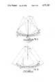
- FIG. 4is a view of two sectioning planes obtained by rotation of the scanner of FIG. 3 through 90° about the axis of the disintegrator;
- FIG. 5is a view of two sectioning planes obtained by rotation of the scanner of FIG. 3 through 180° about the axis of the disintegrator;
- FIG. 6is a view of a series of sectioning planes obtained by pivotal displacement of the scanner of FIG. 3;
- FIG. 7is a view of a series of sectioning planes obtained by axial displacement of the scanner of FIG. 3;
- FIG. 8is a view of a B-scanner in accordance with a fourth embodiment
- FIG. 9is a cross-sectional view to diagrammatically illustrate a pivotal displacement of the scanner of FIG. 8;
- FIG. 10is a cross-sectional view to diagrammatically illustrate the lateral displacement of the scanner of FIG. 8;
- FIGS. 11 and 12are front views of a monitor to illustrate how a concretion is located using a monitor.
- FIG. 13is a block diagram to illustrate the circuitry for receiving and monitoring echo signals generated by the shock waves of the transducer.
- a shock wave transducer means or transducer 1has the shape of a spheroidal cap or cup, in which individual piezo-electric transducer elements not shown in particular are installed, and have their effective emitter surface aligned on the focus point 2.
- Such a focussing transduceris disclosed in the copending U.S. application Ser. No. 614,145, and consequently need not be described in particular.
- a B-scanner 3is secured to the top end of a support 4 in such a manner that the longitudinal axis 5 of the scanner coincides with the symmetry axis 6 of the shock wave transducer 1.
- the support 4passes through the center of the transducer 1, which lacks any transducer elements in a central area la so that the support 4 and the scanner 3 will be situated within a sound shadow having a peripheral shape of a cone 7, even if as in this case, the scanner of its support projects comparatively far out of the space enclosed by the spheroidal cap shape of the transducer 1.
- the external outline of the shock wave field intersecting in the focus point 2has been delineated by the cone 8.
- the concretion 12, which is present in a kidney 10 of the patient 11 and on which the focus or focal point 2 is already aligned in this case,should be situated in the sectioning plane 9, which is detected by the scanner 3 and lies in the plane of the drawing.
- the deviceincludes first means 40 for moving the support 4 and the scanner 3.
- the first meansturns or rotates the scanner 3 in the direction of the arrow A around the symmetry axis 6.
- the first meansmay turn the scanner within an angular range of 90°, so that at least two appropriately angularly staggered section images may be generated.
- the scanner 3may moreover be displaced by the first means 40 in the direction of the double-headed arrow B by axial displacement of the support 4 with respect to the transducer 1, to give satisfactory adaptation of the scanner position to the patient 11.
- Another possible axial position of the support 4 and of the sectioning plane 9is shown in broken lines in FIG. 1.
- the scanner 3projects comparatively far into the conventional commutation field geometry of the transducer 1 and thus has a correspondingly smaller spacing from the concretion 12 from the start, it is advantageously possible to make use of a short-focus scanner which is commercially available and thus more advantageously priced.
- This advantagewill not commonly be available in a device of the type illustrated in FIG. 2, in which the scanner 3 is situated actually within or immediately adjacent to the space enclosed by the cup shape of the transducer 1, and cannot be displaced axially.
- this embodimenthas the advantage that only a comparatively small area need be kept free of transducer elements at the center of the transducer cup, to place the scanner and its support in a shadow.
- the carrier or support 4 together with the scanner 3is mounted by the first means (not illustrated) for rotation around the symmetry axis 6 (arrow A) at the center of the transducer.
- Displaying multiple sectioning planes 9is thereby possible as in the example described in the foregoing. Seven different sectioning planes 9 are depicted and are spread over 360° in FIG. 2. It will however be possible to manage in practice with two sectioning planes staggered through an angle of 90° for example and thereby to allow accurate location of the concretion.
- the two devices according to FIGS. 1 and 2comply with ideal conditions for locating and destroying bodily concretions, since the transducer 1 and the B-scanner 3 are situated on the same axis 6 and since identical tissue strata are traversed for this reason by the sonic locating field as well as by the shock wave sonic field. It is consequently not normally possible to cause refractions of the wave fronts of the two sonic fields causing possible differential image defects.
- the B-scannermay also be installed offset from the symmetry axis 6 on a marginal area of the transducer 1 and be turned by the first means with respect to the transducer around the symmetry axis 6.
- FIGS. 3-7show some realizable possibilities in diagrammatical and greatly simplified manner.
- the scanner 3is so secured on a support 13 that it has its axis fixedly aligned on the focal point or focus 2 of the transducer 1, as shown by the arrows C.
- the supportmay moreover be turned together with the scanner around the axis 6 by the first means 40 in the direction of the arrow A in this case, that is to say for example through 90° from the left-hand position in the drawing to the rear position, so that two different sectioning planes 9a, 9b (FIG. 4) are the result. If the scanner is povoted by the first means from the one position through 180° to another position with respect to the transducer in the corresponding manner, two sectioning planes 9a and 9c (FIG. 5) will result.
- the first meanscan have a displacement of the support and the B-scanner with respect to the transducer for the purpose of generating several section images.
- the displacementmay be either a pivotal displacement of the support and scanner in the direction of the arrow D around a fixed point (FIG. 6) or an axial displacement in the direction of the arrow E (FIG. 7).
- the displacement of the sectioning planesis either offset in a fanlike manner in one case or offset in a tier-like manner in the other case.
- the B-scanner 14is in the form of a strip comprising at least one piezo-electric transducer element. It extends in the plane of the spheroidal shock wave transducer 1 and through its center, so that in this case too, the symmetry axis 6 of the transducer coincides with the axis of the B-scanner.
- the support 15 for the transducer element or transducer elements 14may be pivoted by the first means out of the center and around a bearing point 16 with respect to the transducer 1, as can be seen in FIG. 9. Additionally or instead, the support 15 and scanner may be displaced linearly according to FIG. 10, so that several sectioning planes will be the result as denoted by dash-dotted lines in FIGS. 9 and 10. Since an unequivocal location of the concretion by means of the B-section images thus produced may well still not be possible by this method, the shock wave transducer 1 should also be rotatably arranged around the symmetry axis 6 together with the scanner 14, so that even more section images staggered by means of preset angles of rotation may be displayed in this manner.
- the display of the concretion 12is placed in coincidence with the target mark by displacement of the patient or by displacing the device on one coordinate by means 41 for effecting relative movement (FIG. 1).
- the B-scanneris then displaced to generate another section image 9d and the concretion is placed in coincidence with the same target mark 50 (FIG. 11) or with another target mark 50 (FIG. 12) decisive for this image plane.
- a second coordinateis also determined in this connection and the focus of the shock wave transducer preset by means of the target mark is situated on or within the concretion and that the transducer may now be placed in operation to disintegrate the concretion.
- shock wave transducermay complementarily also be utilized as an Ascanner to display a pulse echo 18 on the monitor 17 and arrange matters by displacement of the A-scanner so that it is known precisely thanks to a third coordinate, whether the transducer focus is correctly adjusted or whether the transducer still has to be displaced along this coordinate.
- the correct settingis reached in any case when the maximum of the echo is situated below the concretion 12 depicted, accordng to FIG. 11, or coincides with another target mark 19 as shown in FIG. 12.
- the B-scanneris axially displaceable as in the examples of embodiment according to FIGS. 1 and 7, it will be necessary to scribe a target mark on the monitor for each of the sectioning planes which are preset and may be obtained by axial displacement, in which connection it is possible to make do with a single target mark in a device as shown in FIGS. 2 and 3.
- a pulse generator 21(FIG. 13) driving the shock wave transducer 1 and the scanner 3 are so synchronized in respect of the sweep motion of its transducer element of reception crystal, that the echo signal 20 may in each case be received when the axis of the transducer element, when switched to reception, is situated precisely on the symmetry axis 6 of the transducer 1.
- FIG. 13the components appertaining to the ultrasonic B-location system are situated in a box 22 illustrated by broken lines.
- This systemcomprises a transmitter 23 and a receiver 24 which are alternately switched to the scanner 3 via a rapid-action switch 25, so that the same is periodically switched between the transmission and reception modes is each case.
- the echo signal 20 received by the scannerpasses via the switch 25 to the receiver 24 and from the latter to an image processing device 26 which processes the signal for subsequent display on the monitor 17.
- a synchronous signalis generated by the receiver 24 via a synchronizing unit or means 27 and by the image processing means 26 at the appropriate instant, and this is interlinked via an AND gate 28 with a trigger signal from a trigger system 29 controlling the pulse generator 21.
- Thisrenders a triggering action on the pulse generator 21 possible in each case only if the reception conditions of the location system are present.
- a synchronizing actionis also possible however in corresponding manner, if the B-scanner is not operated by mechanical sweep but by electrical sweep.
- the additional scannercan be either fixedly or displaceably arranged with respect to the shock wave transducer.
- the first means for displacement of the scanner and supportmay be produced in optional manner and by means known per se.
- the displacementmay be performed by means of an electric motor which may transmit drive either directly or via gearing to the rotatably mounted support and if appropriate also in an axially displaceable manner.
Landscapes
- Health & Medical Sciences (AREA)
- Life Sciences & Earth Sciences (AREA)
- Surgery (AREA)
- Nuclear Medicine, Radiotherapy & Molecular Imaging (AREA)
- Medical Informatics (AREA)
- General Health & Medical Sciences (AREA)
- Veterinary Medicine (AREA)
- Engineering & Computer Science (AREA)
- Biomedical Technology (AREA)
- Heart & Thoracic Surgery (AREA)
- Radiology & Medical Imaging (AREA)
- Molecular Biology (AREA)
- Animal Behavior & Ethology (AREA)
- Public Health (AREA)
- Vascular Medicine (AREA)
- Orthopedic Medicine & Surgery (AREA)
- Physics & Mathematics (AREA)
- Biophysics (AREA)
- Pathology (AREA)
- Surgical Instruments (AREA)
- Ultra Sonic Daignosis Equipment (AREA)
Abstract
Description
1. Field of the Invention
The invention relates to a device for spatial location and destruction of concretions in bodily cavities by application of ultrasonic shock waves which are generated in pulsed manner by a focussing shockwave transducer having its focus adjustable on the concretion in question. The transducer may, if applicable, be operated at reduced power according to the pulse echo principle as an A-scanner during the locating operation, whereas it is possible by means of at least one B-scanner to generate a B-section picture of the body tissue traversed by the ultrasonic field of a monitor, so that by means of a relative displacement between the patient and the device, the concretion depicted in the section picture may be placed in coincidence with a target mark present on the monitor and indicating the position of the transducer focus, and the shock wave transducer may subsequently be placed in operation for the purpose of destroying the concretion with the sonic pressure waves generated during the locating and destruction operations being transmitted to the patient's body via a coupling fluid.
2. Description of the Prior Art
Devices of this kind have proved themselves in the location and destruction of concretions, such as kidney, bladder and gall stones, primarily because as compared to surgical intervention, their application is less dangerous to the patient in view of the contactless destruction of the concretion in question. Difference in the function and application of the known devices derive in essence from the nature of the shock wave generation.
Various arrangements are known for providing the required coupling between a shock wave transducer and the patient. Examples are disclosed in U.S. Pat. No. 4,526,168, whose disclosure is incorporated by reference thereto and which was based on German application No. 3119295; in U.S. Pat. No. 3,237,623; in German applications Nos. 2913251 and 3220751; and in copending U.S. patent application Ser. No. 614,145, which was filed May 25, 1984 and is based on German application No. 3319871.
There are devices disclosed for example in U.S. Pat. No. 3,942,531 which claimed priority from German application 2351247 and German patent specifications Nos. 2718847; 2722252; 2913251; 3122056 and 3220751 in which the shock waves are generated by spark discharge at a focus of a partially eliptical focussing chamber and the other focus may be placed in coincidence with the concretion which is to be destroyed, by adjustment of the device. Relatively high striking voltages are required for spark discharges, as known, so that problems arise in the provision of suitable electrical insulation for the patient, which are costly to resolve. Furthermore, spark discharges lead to burn-off of the electrodes, so that a commensurate maintenance cost will occur.
Ultrasonic transducers will be more satisfactory in this connection, if they comprise one or more commonly, several ceramic elements and are operated by voltage in a pulsed manner, for example, in water as a coupling fluid with respect to the patient. Transducers of this nature, which are disclosed for example in U.S. patent application Ser. No. 614,145, German patent application No. 654673, the above mentioned U.S. Pat. No. 4,526,168 and U.S. Pat. No. 4,607,931, whose disclosure is incorporated by reference and claims priority from the same French application as EP specification No. 148653, are advantageous, in particular because of their durability and risk-free application. Focussing transducers may also be produced in comparatively uncomplicated manner, by mosaic-like positioning of individual transducer elements on a support in the shape of a spheroidal cap or cup, for example. On the other hand, an electronic focussing action is also possible in the case of such transducers assembled from several transducer elements, by appropriate chronologically staged actuation of the transducer elements.
A special problem arises however in these devices in connection with the location of the concretion and the alignment of the focus of the shock wave transducer on the concretion. In this connection, an adjustment under X-ray observation is not advisable in view of the patient's radiation exposure. For this reason, the method has already been adapted to generate sectional pictures of the organ or body area in question by means of B-scanners and to adjust the focus of the shock wave transducer with respect to the concretion under observation of the section pictures on monitors. If, for example, two scanners arranged at an angle of 90° with respect to each other are utilized, the concretions may be clearly depicted on the monitor in two sectioning planes and the focus may if applicable still be adjusted in another plane relative to the concretion by displacement of the shock wave transducer.
It will frequently be sufficient however if the position of the focus is indicated on the monitor by means of a target mark, and if the concretion displayed on the monitor by means of the sectional pictures is placed in coincidence with the target mark by displacement of the device or variation of the patient's position. The shock wave transducer may furthermore also be involved in the locating operation, by allowing it to operate at comparatively low power as an A-scanner in a transceiver mode or rather according to the pulse echo principle. It is possible upon occurrence of a typical maximum of the echo signals being equally displayed on the monitor, to determine whether the transducer focus will be situated within or on the concretion.
It is an object of the invention to provide a device for locating and destroying a concretion, which simplifies the components required for the purpose of location and is thus economic, and which also allows direct optical display of the shattering operation. Furthermore, the reliability and precision of the location of concretions is to be improved.
These objects are achieved in accordance with the invention in that a device of the type referred to above is so constructed that the B-scanner is displaceable on a support by first means for moving the scanner and support with respect to the symmetry axis of the shock wave transducer or transducer means. In this connection, the support and B-scanner may be rotatable by the first means around the symmetry axis of the shock wave transducer. Additionally or alternatively the B-scanner may be axially displaceable by the first means.
An arrangement, which is structurally uncomplicated and reliable regarding the locating operation, can be obtained if the symmetry axis of the shock wave transducer and the longitudinal axis of the B-scanner coincide. This does not however prevent the B-scanner from being installed on a rim of the shock wave transducer means for example, and furthermore from being pivoted or turned along an arc with respect to the symmetry axis of the transducer.
The displaceability of the B-scanner with respect to the shock wave transducer establishes the possibility, depending on the number of scanner settings selected, of placing a plurality of sectioning planes through the corresponding section of the body and thereby establishing a comparatively high degree of spatial resolution of the section in which the concretion is presumed to be located. If the concretion is visible in a sectioning plane on the monitor and has been placed in coincidence with the target mark denoting the transducer focus by relative displacement between the patient and the shock wave transducer, at least one plane or spatial coordinate is determined for the position of the focus with respect to the concretion.
After displacing the B-scanner to another position, for example by turning it through 90°, the position of the concretion in another sectioning plane is sought and found in the manner referred to in the foregoing, so that another coordinate is established, which will normally be sufficient to establish, with some certainty, that the transducer focus and the concretion have the same position or that the concretion is at least situated on the symmetry axis of the transducer. The transducer also may be axially displaced in this case until its focus is situated on the concretion. To this end, the transducer will operate as an A-scanner. Following this, the transducer is operated in a pulsed manner under full power to destroy the concretion.
The possibility exists moreover by means of the B-scanner, to receive a shock wave echo reflected by the concretion and to display the same on the monitor, so that the position of the focus may be constantly verified optically even during the application of the shock waves.
To this end, the control for the pulse generator operating the shock wave transducer and the B-scanner will include means for synchronising the shock wave transducer and B-scanner in such a manner that the shock wave echo signal can be received by the B-scanner. If the transducer element of the B-scanner is wobbled mechanically, the synchronization is performed in such manner that the axis of the transducer element, when switched to reception, is situated on the symmetry axis of the shock wave transducer upon arrival of the shock wave echo signal.
Further objects and advantages of the invention will be understood from the detailed description, read in conjunction with the accompanying drawings wherein preferred embodiments of the invention are illustrated.
FIG. 1 is a diagrammatical perspective view of a scanner/disintegrator according to a first embodiment of the invention being focussed on a concretion;
FIG. 2 is a diagrammatical view of a second embodiment;
FIG. 3 is a diagrammatical view of a third embodiment;
FIG. 4 is a view of two sectioning planes obtained by rotation of the scanner of FIG. 3 through 90° about the axis of the disintegrator;
FIG. 5 is a view of two sectioning planes obtained by rotation of the scanner of FIG. 3 through 180° about the axis of the disintegrator;
FIG. 6 is a view of a series of sectioning planes obtained by pivotal displacement of the scanner of FIG. 3;
FIG. 7 is a view of a series of sectioning planes obtained by axial displacement of the scanner of FIG. 3;
FIG. 8 is a view of a B-scanner in accordance with a fourth embodiment;
FIG. 9 is a cross-sectional view to diagrammatically illustrate a pivotal displacement of the scanner of FIG. 8;
FIG. 10 is a cross-sectional view to diagrammatically illustrate the lateral displacement of the scanner of FIG. 8;
FIGS. 11 and 12 are front views of a monitor to illustrate how a concretion is located using a monitor; and
FIG. 13 is a block diagram to illustrate the circuitry for receiving and monitoring echo signals generated by the shock waves of the transducer.
In all the devices illustrated in the drawings, a shock wave transducer means or transducer 1 has the shape of a spheroidal cap or cup, in which individual piezo-electric transducer elements not shown in particular are installed, and have their effective emitter surface aligned on the focus point 2. Such a focussing transducer is disclosed in the copending U.S. application Ser. No. 614,145, and consequently need not be described in particular.
In the device according to FIG. 1, a B-scanner 3 is secured to the top end of a support 4 in such a manner that thelongitudinal axis 5 of the scanner coincides with thesymmetry axis 6 of the shock wave transducer 1. The support 4 passes through the center of the transducer 1, which lacks any transducer elements in a central area la so that the support 4 and the scanner 3 will be situated within a sound shadow having a peripheral shape of a cone 7, even if as in this case, the scanner of its support projects comparatively far out of the space enclosed by the spheroidal cap shape of the transducer 1.
The external outline of the shock wave field intersecting in the focus point 2 has been delineated by the cone 8. Theconcretion 12, which is present in a kidney 10 of the patient 11 and on which the focus or focal point 2 is already aligned in this case, should be situated in the sectioningplane 9, which is detected by the scanner 3 and lies in the plane of the drawing.
Furthermore, the device includes first means 40 for moving the support 4 and the scanner 3. In FIG. 1, the first means turns or rotates the scanner 3 in the direction of the arrow A around thesymmetry axis 6. For example, the first means may turn the scanner within an angular range of 90°, so that at least two appropriately angularly staggered section images may be generated. The scanner 3 may moreover be displaced by the first means 40 in the direction of the double-headed arrow B by axial displacement of the support 4 with respect to the transducer 1, to give satisfactory adaptation of the scanner position to the patient 11. Another possible axial position of the support 4 and of the sectioningplane 9 is shown in broken lines in FIG. 1.
If, as in the embodiment of FIG. 1, the scanner 3 projects comparatively far into the conventional commutation field geometry of the transducer 1 and thus has a correspondingly smaller spacing from theconcretion 12 from the start, it is advantageously possible to make use of a short-focus scanner which is commercially available and thus more advantageously priced. This advantage will not commonly be available in a device of the type illustrated in FIG. 2, in which the scanner 3 is situated actually within or immediately adjacent to the space enclosed by the cup shape of the transducer 1, and cannot be displaced axially. On the other hand, this embodiment has the advantage that only a comparatively small area need be kept free of transducer elements at the center of the transducer cup, to place the scanner and its support in a shadow.
In FIG. 2, the carrier or support 4 together with the scanner 3 is mounted by the first means (not illustrated) for rotation around the symmetry axis 6 (arrow A) at the center of the transducer. Displayingmultiple sectioning planes 9 is thereby possible as in the example described in the foregoing. Sevendifferent sectioning planes 9 are depicted and are spread over 360° in FIG. 2. It will however be possible to manage in practice with two sectioning planes staggered through an angle of 90° for example and thereby to allow accurate location of the concretion. Since the scanner will after completion of the locating operation and also during operation of the transducer 1 remain in its illustrated position and be able to generate B-images currently, a B-scanner of comparatively long focus or focal range will moreover be needed in this device on the one hand, but on the other hand an ultrasonic check via the scanner is also possible during application of the shock waves.
As for the rest, the two devices according to FIGS. 1 and 2 comply with ideal conditions for locating and destroying bodily concretions, since the transducer 1 and the B-scanner 3 are situated on thesame axis 6 and since identical tissue strata are traversed for this reason by the sonic locating field as well as by the shock wave sonic field. It is consequently not normally possible to cause refractions of the wave fronts of the two sonic fields causing possible differential image defects.
If, however, such image defects or aberrations do not occur or are negligible in connection with the location, display and locus of the shock wave focus, the B-scanner may also be installed offset from thesymmetry axis 6 on a marginal area of the transducer 1 and be turned by the first means with respect to the transducer around thesymmetry axis 6. To this end, FIGS. 3-7 show some realizable possibilities in diagrammatical and greatly simplified manner.
According to FIG. 3, the scanner 3 is so secured on a support 13 that it has its axis fixedly aligned on the focal point or focus 2 of the transducer 1, as shown by the arrows C. The support may moreover be turned together with the scanner around theaxis 6 by the first means 40 in the direction of the arrow A in this case, that is to say for example through 90° from the left-hand position in the drawing to the rear position, so that twodifferent sectioning planes planes
The first means can have a displacement of the support and the B-scanner with respect to the transducer for the purpose of generating several section images. The displacement may be either a pivotal displacement of the support and scanner in the direction of the arrow D around a fixed point (FIG. 6) or an axial displacement in the direction of the arrow E (FIG. 7). The displacement of the sectioning planes is either offset in a fanlike manner in one case or offset in a tier-like manner in the other case.
Another possibility for a particular embodiment and displacement of the B-scanner emerges from FIGS. 8-10. In this case, the B-scanner 14 is in the form of a strip comprising at least one piezo-electric transducer element. It extends in the plane of the spheroidal shock wave transducer 1 and through its center, so that in this case too, thesymmetry axis 6 of the transducer coincides with the axis of the B-scanner.
Thesupport 15 for the transducer element ortransducer elements 14 may be pivoted by the first means out of the center and around abearing point 16 with respect to the transducer 1, as can be seen in FIG. 9. Additionally or instead, thesupport 15 and scanner may be displaced linearly according to FIG. 10, so that several sectioning planes will be the result as denoted by dash-dotted lines in FIGS. 9 and 10. Since an unequivocal location of the concretion by means of the B-section images thus produced may well still not be possible by this method, the shock wave transducer 1 should also be rotatably arranged around thesymmetry axis 6 together with thescanner 14, so that even more section images staggered by means of preset angles of rotation may be displayed in this manner.
Upon locating a concretion, use is normally made of at least onemonitor 17 in conjunction with target marks 50, as described in the following in connection with FIGS. 11 and 12. If it is possible to manage with two section images during the locating operation, which is commonly the case, it is possible to scribe one target mark 50 (FIG. 11) or two target marks 50 (FIG. 12) for bothsection kidney images section image 9c, the display of theconcretion 12 is placed in coincidence with the target mark by displacement of the patient or by displacing the device on one coordinate bymeans 41 for effecting relative movement (FIG. 1).
The B-scanner is then displaced to generate anothersection image 9d and the concretion is placed in coincidence with the same target mark 50 (FIG. 11) or with another target mark 50 (FIG. 12) decisive for this image plane. Thus, it is possible to be certain that a second coordinate is also determined in this connection and the focus of the shock wave transducer preset by means of the target mark is situated on or within the concretion and that the transducer may now be placed in operation to disintegrate the concretion.
It is, however, also possible and known that the shock wave transducer may complementarily also be utilized as an Ascanner to display apulse echo 18 on themonitor 17 and arrange matters by displacement of the A-scanner so that it is known precisely thanks to a third coordinate, whether the transducer focus is correctly adjusted or whether the transducer still has to be displaced along this coordinate. The correct setting is reached in any case when the maximum of the echo is situated below theconcretion 12 depicted, accordng to FIG. 11, or coincides with anothertarget mark 19 as shown in FIG. 12.
If the B-scanner is axially displaceable as in the examples of embodiment according to FIGS. 1 and 7, it will be necessary to scribe a target mark on the monitor for each of the sectioning planes which are preset and may be obtained by axial displacement, in which connection it is possible to make do with a single target mark in a device as shown in FIGS. 2 and 3.
It is possible by means of the device shown in FIG. 13 to receive theecho signal 20 generated by the shock wave of the transducer on theconcretion 12 by means of the B-scanner 3 and to display this on themonitor 17. Apart from the normal ultrasonic B-datum, complementary information is secured thereby by superimposition of the shock wave echo. As a matter of fact, if the concretion is struck by the shock wave, a brightly shining area of the order of magnitude of the shock wave focus appears on the monitor, whereby it is then possible to determine precisely by eye, whether the concretion has been struck.
To accomplish this, a pulse generator 21 (FIG. 13) driving the shock wave transducer 1 and the scanner 3 are so synchronized in respect of the sweep motion of its transducer element of reception crystal, that theecho signal 20 may in each case be received when the axis of the transducer element, when switched to reception, is situated precisely on thesymmetry axis 6 of the transducer 1.
In FIG. 13, the components appertaining to the ultrasonic B-location system are situated in abox 22 illustrated by broken lines. This system comprises atransmitter 23 and areceiver 24 which are alternately switched to the scanner 3 via a rapid-action switch 25, so that the same is periodically switched between the transmission and reception modes is each case. Theecho signal 20 received by the scanner passes via theswitch 25 to thereceiver 24 and from the latter to animage processing device 26 which processes the signal for subsequent display on themonitor 17.
Since the reception of the shock wave echo in the case of a mechanical sweep scanner is possibly only in case of alignment of the reception crystal on the incoming echo signal, the synchronization already referred to earlier is required. For this reason, a synchronous signal is generated by thereceiver 24 via a synchronizing unit or means 27 and by the image processing means 26 at the appropriate instant, and this is interlinked via an ANDgate 28 with a trigger signal from atrigger system 29 controlling thepulse generator 21. This renders a triggering action on thepulse generator 21 possible in each case only if the reception conditions of the location system are present. A synchronizing action is also possible however in corresponding manner, if the B-scanner is not operated by mechanical sweep but by electrical sweep.
In conclusion, it is also pointed out that an adequate number of section images may well already be generated by means of a single scanner in view of the displaceability of the scanner support, which should not however bar another B-scanner from being placed in operation if appropriate. The additional scanner can be either fixedly or displaceably arranged with respect to the shock wave transducer. The first means for displacement of the scanner and support may be produced in optional manner and by means known per se. For example, the displacement may be performed by means of an electric motor which may transmit drive either directly or via gearing to the rotatably mounted support and if appropriate also in an axially displaceable manner.
Although various minor modifications may be suggested by those adverse in the art, it should be understood that we wish to embody within the scope of the patent granted hereon all such modifications as reasonably and properly come within the scope of our contribution to the art.
Claims (16)
1. A device for spatial location and destruction of a concretion in a bodily cavity of a patient, comprising a focussing shock wave transducer means for producing ultrasonic waves and having an axis of symmetry and a focus alignable with the concretion to be destroyed, a B-scanner arranged to generate a B-section image of bodily tissue of the patient traversed by the ultrasonic waves from said transducer means, a displaceable support means for mounting the B-scanner to move with the transducer means, said support means having first means to displace the B-scanner relative to the transducer means along a displacement axis that extends between the B-scanner and the focus of the transducer means, a monitor means for displaying said image, means for defining at least one target mark on said monitor means indicating the position of the transducer focus, and means for effecting relative movement between the patient and the device to bring the concretion depicted in said image into coincidence with said target mark, said shock wave transducer means adapted to generate ultrasonic shock waves in a pulsed manner to destroy the concretion at said focus.
2. A device according to claim 1, wherein said shock wave transducer means is adapted for operation at reduced power, as an A-scanner according to the pulse echo principle, for location of the concretion .
3. A device according to claim 1, wherein said first means comprises means for rotating the B-scanner around the symmetry axis of the shock wave transducer means.
4. A device according to claim 1, wherein the support means mounts the B-scanner with the symmetry axis of the shock wave transducer means and the longitudinal axis of the B-scanner coinciding.
5. A device according to claim 4, wherein the shock wave transducer means comprises individual piezoelectric transducer elements assembled into the form of a spheroidal cap, wherein the support means extends through a center of the shock wave transducer means which is unobstructed by transducer elements, and wherein the transducer elements are so arranged that the support means is situated within a sound shadow during operation of the shock wave transducer means.
6. A device according to claim 5, wherein the B-scanner on the support means projects outwards beyond the volume enclosed by the transducer cap.
7. A device according to claim 1, wherein the device further comprises pulse generator means for driving the transducer means, and means for synchronizing the pulse generator and the B-scanner so that a shock wave echo signal reflected off the concretion is received by the B-scanner.
8. A device according to claim 7, wherein the B-scanner includes a transducer element, wherein the first means comprises means for mechanically rocking the transducer element of the B-scanner, and wherein the synchronizing means comprises means for ensuring that the axis of the transducer element of the B-scanner, when switched for reception, is situated on the axis of symmetry of the shock wave transducer means at the impingement of the shock wave echo signal.
9. A device for spatial location and destruction of a concretion in a bodily cavity of a patient, comprising a focussing shock wave transducer means for producing ultrasonic waves and having an axis of symmetry and a focus alignable with the concretion to be destroyed, a B-scanner arranged to generate a B-section image of bodily tissue of the patient traversed by the ultrasonic waves from said transducer means, a displaceable support means for mounting the B-scanner to move with the transducer means, said support means having first means to displace the B-scanner relative to the transducer means along a displacement axis that extends away from the transducer means on the side of the transducer means that includes the focus such that the B-scanner is displaceable away from the transducer in a direction that includes a component parallel to the symmetry axis, a monitor means for displaying said image, means for defining at least one target mark on said monitor means indicating the position of the transducer focus, and means for effecting relative movement between the patient and the device to bring the concretion depicted in said image into coincidence with said target mark, said shock wave transducer means adapted to generate ultrasonic shock waves in a pulsed manner to destroy the concretion at said focus.
10. A device according to claim 9, wherein said shock wave transducer means is adapted for operation at reduced power, as an A-scanner according to the pulse echo principle, for location of the concretion.
11. A device according to claim 9, wherein said first means comprises means for rotating the B-scanner around the symmetry axis of the shock wave transducer means.
12. A device according to claim 9, wherein the support means mounts the B-scanner with the symmetry axis of the shock wave transducer means and the longitudinal axis of the B-scanner coinciding.
13. A device according to claim 9, wherein the shock wave transducer means comprises individual piezoelectric transducer elements assembled into the form of a spheroidal cap, wherein the support means extends through a center of the shock wave transducer means which is unobstructed by transducer elements, and wherein the transducer elements are so arranged that the support means is situated within a sound shadow during operation of the shock wave transducer means.
14. A device according to claim 13, wherein the B-scanner on the support means projects outwards beyond the volume enclosed by the transducer cap.
15. A device according to claim 9, wherein the device further comprises pulse generator means for driving the transducer means, and means for synchronizing the pulse generator and the B-scanner so that a shock wave echo signal reflected off the concretion is received by the B-scanner.
16. A device according to claim 15, wherein the B-scanner includes a transducer element, wherein the first means comprises means for mechanically rocking the transducer element of the B-scanner, and wherein the synchronizing means comprises means for ensuring that the axis of the transducer element of the B-scanner, when switched for reception, is situated on the axis of symmetry of the shock wave transducer means at the impingement of the shock wave echo signal.
Applications Claiming Priority (2)
| Application Number | Priority Date | Filing Date | Title |
|---|---|---|---|
| DE3543867ADE3543867C3 (en) | 1985-12-12 | 1985-12-12 | Device for the spatial location and destruction of concrements in body cavities |
| DE3543867 | 1985-12-12 |
Related Child Applications (1)
| Application Number | Title | Priority Date | Filing Date |
|---|---|---|---|
| US07/244,747DivisionUS4821730A (en) | 1985-12-12 | 1988-09-14 | Ultrasonic scanner and shock wave generator |
Publications (1)
| Publication Number | Publication Date |
|---|---|
| US4771787Atrue US4771787A (en) | 1988-09-20 |
Family
ID=6288241
Family Applications (2)
| Application Number | Title | Priority Date | Filing Date |
|---|---|---|---|
| US06/940,445Expired - Fee RelatedUS4771787A (en) | 1985-12-12 | 1986-12-11 | Ultrasonic scanner and shock wave generator |
| US07/244,747Expired - Fee RelatedUS4821730A (en) | 1985-12-12 | 1988-09-14 | Ultrasonic scanner and shock wave generator |
Family Applications After (1)
| Application Number | Title | Priority Date | Filing Date |
|---|---|---|---|
| US07/244,747Expired - Fee RelatedUS4821730A (en) | 1985-12-12 | 1988-09-14 | Ultrasonic scanner and shock wave generator |
Country Status (3)
| Country | Link |
|---|---|
| US (2) | US4771787A (en) |
| DE (1) | DE3543867C3 (en) |
| FR (1) | FR2591467B1 (en) |
Cited By (118)
| Publication number | Priority date | Publication date | Assignee | Title |
|---|---|---|---|---|
| US4821730A (en)* | 1985-12-12 | 1989-04-18 | Richard Wolf Gmbh | Ultrasonic scanner and shock wave generator |
| US4858613A (en)* | 1988-03-02 | 1989-08-22 | Laboratory Equipment, Corp. | Localization and therapy system for treatment of spatially oriented focal disease |
| US4888746A (en)* | 1987-09-24 | 1989-12-19 | Richard Wolf Gmbh | Focussing ultrasound transducer |
| US4915114A (en)* | 1987-10-19 | 1990-04-10 | Siemens Aktiengesellschaft | Shock wave source having central locating system & disposed in a cavity free of shock waves |
| US4928672A (en)* | 1987-07-31 | 1990-05-29 | Siemens Aktiengesellschaft | Shockwave source having a centrally disposed ultrasound locating system |
| US4932414A (en)* | 1987-11-02 | 1990-06-12 | Cornell Research Foundation, Inc. | System of therapeutic ultrasound and real-time ultrasonic scanning |
| US4945898A (en)* | 1989-07-12 | 1990-08-07 | Diasonics, Inc. | Power supply |
| US4949708A (en)* | 1987-11-06 | 1990-08-21 | Shimadzu Corporation | Hypothermia apparatus |
| US4951653A (en)* | 1988-03-02 | 1990-08-28 | Laboratory Equipment, Corp. | Ultrasound brain lesioning system |
| US4962754A (en)* | 1988-01-13 | 1990-10-16 | Kabushiki Kaisha Toshiba | Shock wave treatment apparatus |
| US4976255A (en)* | 1988-08-17 | 1990-12-11 | Siemens Aktiengesellschaft | Apparatus for extracorporeal lithotripsy using shock waves and therapeutic ultrasound |
| US4984565A (en)* | 1988-12-09 | 1991-01-15 | Siemens Aktiengesellschaft | Extracorporeal lithotriptor with x-ray locating system |
| US4984575A (en)* | 1987-04-16 | 1991-01-15 | Olympus Optical Co., Ltd. | Therapeutical apparatus of extracorporeal type |
| US4986275A (en)* | 1987-08-05 | 1991-01-22 | Kabushiki Kaisha Toshiba | Ultrasonic therapy apparatus |
| US4986259A (en)* | 1989-02-28 | 1991-01-22 | Kabushiki Kaisha Toshiba | Apparatus and method for disintegrating calculus |
| US4991604A (en)* | 1988-04-09 | 1991-02-12 | Richard Wolf Gmbh | Ultrasonic treatment apparatus |
| US5005579A (en)* | 1987-02-17 | 1991-04-09 | Richard Wolf Gmbh | Apparatus for spatial location and destruction of objects inside the body by means of ultrasound |
| US5009232A (en)* | 1988-08-17 | 1991-04-23 | Siemens Aktiengesellschaft | Extracorporeal lithotripsy apparatus using high intensity shock waves for calculus disintegration and low intensity shock waves for imaging |
| US5025789A (en)* | 1987-10-19 | 1991-06-25 | Siemens Aktiengesellschaft | Shock wave source having a central ultrasound locating system |
| US5058590A (en)* | 1988-04-30 | 1991-10-22 | Richard Wolf Gmbh | Apparatus for dispersing fluids for dissolution or concretions in a bodily cavity |
| US5065740A (en)* | 1986-12-26 | 1991-11-19 | Kabushiki Kaisha Toshiba | Ultrasonic medical treatment apparatus |
| US5065741A (en)* | 1987-04-16 | 1991-11-19 | Olympus Optical Co. Ltd. | Extracoporeal ultrasonic lithotripter with a variable focus |
| US5065762A (en)* | 1989-06-02 | 1991-11-19 | Siemens Aktiengesellschaft | Extracorporeal lithotripsy apparatus for the disintegration of calculi having an unattenuated locating field |
| US5067493A (en)* | 1985-05-24 | 1991-11-26 | Elscint Ltd. | Lithotripsy system using ultrasound to locate calculi |
| US5072722A (en)* | 1988-05-25 | 1991-12-17 | Siemens Aktiengesellschaft | Device for the spatial ultrasonic location of calculi |
| US5076277A (en)* | 1989-02-17 | 1991-12-31 | Kabushiki Kaisha Toshiba | Calculus destroying apparatus using feedback from a low pressure echo for positioning |
| US5078144A (en)* | 1988-08-19 | 1992-01-07 | Olympus Optical Co. Ltd. | System for applying ultrasonic waves and a treatment instrument to a body part |
| US5095907A (en)* | 1989-06-21 | 1992-03-17 | Kabushiki Kaisha Toshiba | Acoustic wave therapy apparatus |
| US5143074A (en)* | 1983-12-14 | 1992-09-01 | Edap International | Ultrasonic treatment device using a focussing and oscillating piezoelectric element |
| US5144953A (en)* | 1988-11-28 | 1992-09-08 | Richard Wolf Gmbh | Lithotriptor with x-ray alignment system |
| US5159931A (en)* | 1988-11-25 | 1992-11-03 | Riccardo Pini | Apparatus for obtaining a three-dimensional reconstruction of anatomic structures through the acquisition of echographic images |
| US5178135A (en)* | 1987-04-16 | 1993-01-12 | Olympus Optical Co., Ltd. | Therapeutical apparatus of extracorporeal type |
| US5193527A (en)* | 1989-10-03 | 1993-03-16 | Richard Wolf Gmbh | Ultrasonic shock-wave transducer |
| US5215091A (en)* | 1990-05-31 | 1993-06-01 | Kabushiki Kaisha Toshiba | Lithotrity apparatus having a missed-shot preventive function |
| US5243985A (en)* | 1990-05-31 | 1993-09-14 | Kabushiki Kaisha Toshiba | Lithotrity apparatus having a missed-shot preventive function |
| US5271408A (en)* | 1991-03-25 | 1993-12-21 | Siemens Elema Ab | Hydrodynamic system for blood flow measurement |
| US5315986A (en)* | 1988-08-31 | 1994-05-31 | Technomed International | Apparatus for real-time tracking and imaging of objects within the body of a mammal |
| US5431621A (en)* | 1984-11-26 | 1995-07-11 | Edap International | Process and device of an anatomic anomaly by means of elastic waves, with tracking of the target and automatic triggering of the shootings |
| US5851183A (en)* | 1990-10-19 | 1998-12-22 | St. Louis University | System for indicating the position of a surgical probe within a head on an image of the head |
| US5871445A (en)* | 1993-04-26 | 1999-02-16 | St. Louis University | System for indicating the position of a surgical probe within a head on an image of the head |
| US6118845A (en)* | 1998-06-29 | 2000-09-12 | Surgical Navigation Technologies, Inc. | System and methods for the reduction and elimination of image artifacts in the calibration of X-ray imagers |
| US6146390A (en)* | 1992-04-21 | 2000-11-14 | Sofamor Danek Holdings, Inc. | Apparatus and method for photogrammetric surgical localization |
| US6167145A (en)* | 1996-03-29 | 2000-12-26 | Surgical Navigation Technologies, Inc. | Bone navigation system |
| US6226548B1 (en) | 1997-09-24 | 2001-05-01 | Surgical Navigation Technologies, Inc. | Percutaneous registration apparatus and method for use in computer-assisted surgical navigation |
| US6236875B1 (en) | 1994-10-07 | 2001-05-22 | Surgical Navigation Technologies | Surgical navigation systems including reference and localization frames |
| US6347240B1 (en) | 1990-10-19 | 2002-02-12 | St. Louis University | System and method for use in displaying images of a body part |
| US6470207B1 (en) | 1999-03-23 | 2002-10-22 | Surgical Navigation Technologies, Inc. | Navigational guidance via computer-assisted fluoroscopic imaging |
| US6477400B1 (en) | 1998-08-20 | 2002-11-05 | Sofamor Danek Holdings, Inc. | Fluoroscopic image guided orthopaedic surgery system with intraoperative registration |
| US6892090B2 (en) | 2002-08-19 | 2005-05-10 | Surgical Navigation Technologies, Inc. | Method and apparatus for virtual endoscopy |
| US6920347B2 (en) | 2000-04-07 | 2005-07-19 | Surgical Navigation Technologies, Inc. | Trajectory storage apparatus and method for surgical navigation systems |
| US6947786B2 (en) | 2002-02-28 | 2005-09-20 | Surgical Navigation Technologies, Inc. | Method and apparatus for perspective inversion |
| US6968224B2 (en) | 1999-10-28 | 2005-11-22 | Surgical Navigation Technologies, Inc. | Method of detecting organ matter shift in a patient |
| US6978166B2 (en) | 1994-10-07 | 2005-12-20 | Saint Louis University | System for use in displaying images of a body part |
| US6990368B2 (en) | 2002-04-04 | 2006-01-24 | Surgical Navigation Technologies, Inc. | Method and apparatus for virtual digital subtraction angiography |
| US7007699B2 (en) | 1999-10-28 | 2006-03-07 | Surgical Navigation Technologies, Inc. | Surgical sensor |
| US7085400B1 (en) | 2000-06-14 | 2006-08-01 | Surgical Navigation Technologies, Inc. | System and method for image based sensor calibration |
| US7174202B2 (en) | 1992-08-14 | 2007-02-06 | British Telecommunications | Medical navigation apparatus |
| US7217276B2 (en) | 1999-04-20 | 2007-05-15 | Surgical Navigational Technologies, Inc. | Instrument guidance method and system for image guided surgery |
| US7313430B2 (en) | 2003-08-28 | 2007-12-25 | Medtronic Navigation, Inc. | Method and apparatus for performing stereotactic surgery |
| US7366562B2 (en) | 2003-10-17 | 2008-04-29 | Medtronic Navigation, Inc. | Method and apparatus for surgical navigation |
| US20080167555A1 (en)* | 2007-01-05 | 2008-07-10 | Min Kang Qian | High intensity focused ultrasound treatment head and system |
| US7542791B2 (en) | 2003-01-30 | 2009-06-02 | Medtronic Navigation, Inc. | Method and apparatus for preplanning a surgical procedure |
| USRE40852E1 (en) | 1995-06-14 | 2009-07-14 | Medtronic Navigation, Inc. | Method and system for navigating a catheter probe |
| US7567834B2 (en) | 2004-05-03 | 2009-07-28 | Medtronic Navigation, Inc. | Method and apparatus for implantation between two vertebral bodies |
| US7570791B2 (en) | 2003-04-25 | 2009-08-04 | Medtronic Navigation, Inc. | Method and apparatus for performing 2D to 3D registration |
| US7599730B2 (en) | 2002-11-19 | 2009-10-06 | Medtronic Navigation, Inc. | Navigation system for cardiac therapies |
| US7636595B2 (en) | 2004-10-28 | 2009-12-22 | Medtronic Navigation, Inc. | Method and apparatus for calibrating non-linear instruments |
| US7657300B2 (en) | 1999-10-28 | 2010-02-02 | Medtronic Navigation, Inc. | Registration of human anatomy integrated for electromagnetic localization |
| US7660623B2 (en) | 2003-01-30 | 2010-02-09 | Medtronic Navigation, Inc. | Six degree of freedom alignment display for medical procedures |
| US7697972B2 (en) | 2002-11-19 | 2010-04-13 | Medtronic Navigation, Inc. | Navigation system for cardiac therapies |
| US7763035B2 (en) | 1997-12-12 | 2010-07-27 | Medtronic Navigation, Inc. | Image guided spinal surgery guide, system and method for use thereof |
| US7797032B2 (en) | 1999-10-28 | 2010-09-14 | Medtronic Navigation, Inc. | Method and system for navigating a catheter probe in the presence of field-influencing objects |
| US7835778B2 (en) | 2003-10-16 | 2010-11-16 | Medtronic Navigation, Inc. | Method and apparatus for surgical navigation of a multiple piece construct for implantation |
| US7835784B2 (en) | 2005-09-21 | 2010-11-16 | Medtronic Navigation, Inc. | Method and apparatus for positioning a reference frame |
| US7840253B2 (en) | 2003-10-17 | 2010-11-23 | Medtronic Navigation, Inc. | Method and apparatus for surgical navigation |
| US7881770B2 (en) | 2000-03-01 | 2011-02-01 | Medtronic Navigation, Inc. | Multiple cannula image guided tool for image guided procedures |
| US7998062B2 (en) | 2004-03-29 | 2011-08-16 | Superdimension, Ltd. | Endoscope structures and techniques for navigating to a target in branched structure |
| US8074662B2 (en) | 1999-10-28 | 2011-12-13 | Medtronic Navigation, Inc. | Surgical communication and power system |
| US8112292B2 (en) | 2006-04-21 | 2012-02-07 | Medtronic Navigation, Inc. | Method and apparatus for optimizing a therapy |
| US20120046592A1 (en)* | 2010-08-18 | 2012-02-23 | Mirabilis Medica Inc. | Hifu applicator |
| US8165658B2 (en) | 2008-09-26 | 2012-04-24 | Medtronic, Inc. | Method and apparatus for positioning a guide relative to a base |
| USRE43328E1 (en) | 1997-11-20 | 2012-04-24 | Medtronic Navigation, Inc | Image guided awl/tap/screwdriver |
| US8175681B2 (en) | 2008-12-16 | 2012-05-08 | Medtronic Navigation Inc. | Combination of electromagnetic and electropotential localization |
| US8239001B2 (en) | 2003-10-17 | 2012-08-07 | Medtronic Navigation, Inc. | Method and apparatus for surgical navigation |
| USRE43952E1 (en) | 1989-10-05 | 2013-01-29 | Medtronic Navigation, Inc. | Interactive system for local intervention inside a non-homogeneous structure |
| US8452068B2 (en) | 2008-06-06 | 2013-05-28 | Covidien Lp | Hybrid registration method |
| US8473032B2 (en) | 2008-06-03 | 2013-06-25 | Superdimension, Ltd. | Feature-based registration method |
| US8494614B2 (en) | 2009-08-31 | 2013-07-23 | Regents Of The University Of Minnesota | Combination localization system |
| US8494613B2 (en) | 2009-08-31 | 2013-07-23 | Medtronic, Inc. | Combination localization system |
| US8611984B2 (en) | 2009-04-08 | 2013-12-17 | Covidien Lp | Locatable catheter |
| US8644907B2 (en) | 1999-10-28 | 2014-02-04 | Medtronic Navigaton, Inc. | Method and apparatus for surgical navigation |
| US8660635B2 (en) | 2006-09-29 | 2014-02-25 | Medtronic, Inc. | Method and apparatus for optimizing a computer assisted surgical procedure |
| US8663088B2 (en) | 2003-09-15 | 2014-03-04 | Covidien Lp | System of accessories for use with bronchoscopes |
| US8764725B2 (en) | 2004-02-09 | 2014-07-01 | Covidien Lp | Directional anchoring mechanism, method and applications thereof |
| US8905920B2 (en) | 2007-09-27 | 2014-12-09 | Covidien Lp | Bronchoscope adapter and method |
| US8932207B2 (en) | 2008-07-10 | 2015-01-13 | Covidien Lp | Integrated multi-functional endoscopic tool |
| US9055881B2 (en) | 2004-04-26 | 2015-06-16 | Super Dimension Ltd. | System and method for image-based alignment of an endoscope |
| US9168102B2 (en) | 2006-01-18 | 2015-10-27 | Medtronic Navigation, Inc. | Method and apparatus for providing a container to a sterile environment |
| US20170027596A1 (en)* | 2004-09-20 | 2017-02-02 | P Tech, Llc | Acoustic therapy device |
| US9575140B2 (en) | 2008-04-03 | 2017-02-21 | Covidien Lp | Magnetic interference detection system and method |
| US9675424B2 (en) | 2001-06-04 | 2017-06-13 | Surgical Navigation Technologies, Inc. | Method for calibrating a navigation system |
| US9833373B2 (en) | 2010-08-27 | 2017-12-05 | Les Solutions Médicales Soundbite Inc. | Mechanical wave generator and method thereof |
| US10418705B2 (en) | 2016-10-28 | 2019-09-17 | Covidien Lp | Electromagnetic navigation antenna assembly and electromagnetic navigation system including the same |
| US10426555B2 (en) | 2015-06-03 | 2019-10-01 | Covidien Lp | Medical instrument with sensor for use in a system and method for electromagnetic navigation |
| US10446931B2 (en) | 2016-10-28 | 2019-10-15 | Covidien Lp | Electromagnetic navigation antenna assembly and electromagnetic navigation system including the same |
| US10478254B2 (en) | 2016-05-16 | 2019-11-19 | Covidien Lp | System and method to access lung tissue |
| US10517505B2 (en) | 2016-10-28 | 2019-12-31 | Covidien Lp | Systems, methods, and computer-readable media for optimizing an electromagnetic navigation system |
| US10582834B2 (en) | 2010-06-15 | 2020-03-10 | Covidien Lp | Locatable expandable working channel and method |
| US10615500B2 (en) | 2016-10-28 | 2020-04-07 | Covidien Lp | System and method for designing electromagnetic navigation antenna assemblies |
| US10638952B2 (en) | 2016-10-28 | 2020-05-05 | Covidien Lp | Methods, systems, and computer-readable media for calibrating an electromagnetic navigation system |
| US10722311B2 (en) | 2016-10-28 | 2020-07-28 | Covidien Lp | System and method for identifying a location and/or an orientation of an electromagnetic sensor based on a map |
| US10751126B2 (en) | 2016-10-28 | 2020-08-25 | Covidien Lp | System and method for generating a map for electromagnetic navigation |
| US10792106B2 (en) | 2016-10-28 | 2020-10-06 | Covidien Lp | System for calibrating an electromagnetic navigation system |
| US10952593B2 (en) | 2014-06-10 | 2021-03-23 | Covidien Lp | Bronchoscope adapter |
| US11006914B2 (en) | 2015-10-28 | 2021-05-18 | Medtronic Navigation, Inc. | Apparatus and method for maintaining image quality while minimizing x-ray dosage of a patient |
| US11219489B2 (en) | 2017-10-31 | 2022-01-11 | Covidien Lp | Devices and systems for providing sensors in parallel with medical tools |
| US11331150B2 (en) | 1999-10-28 | 2022-05-17 | Medtronic Navigation, Inc. | Method and apparatus for surgical navigation |
| US12089902B2 (en) | 2019-07-30 | 2024-09-17 | Coviden Lp | Cone beam and 3D fluoroscope lung navigation |
Families Citing this family (34)
| Publication number | Priority date | Publication date | Assignee | Title |
|---|---|---|---|---|
| DE3608877A1 (en)* | 1986-03-17 | 1987-09-24 | Non Invasive Therapeutic Tech | DEVICE FOR CRUSHING KIDNEY STONES BY MEANS OF SHOCK WAVES |
| EP0265742A1 (en)* | 1986-10-23 | 1988-05-04 | Siemens Aktiengesellschaft | Lithotripter with a locating device |
| EP0316863B2 (en)* | 1987-11-16 | 2000-11-29 | Kabushiki Kaisha Toshiba | Shock wave treatment apparatus |
| DE3943644C2 (en)* | 1988-01-13 | 1995-11-02 | Toshiba Kawasaki Kk | Shockwave treatment appts. e.g. for destroying caller cells |
| US5036855A (en)* | 1988-03-02 | 1991-08-06 | Laboratory Equipment, Corp. | Localization and therapy system for treatment of spatially oriented focal disease |
| DE3913023C2 (en)* | 1988-04-22 | 1993-10-14 | Toshiba Kawasaki Kk | Shatter wave treatment device |
| DE3833862A1 (en)* | 1988-10-05 | 1990-04-19 | Dornier Medizintechnik | COMBINED SHOCK WAVE SOURCE |
| DE3835318C1 (en)* | 1988-10-17 | 1990-06-28 | Storz Medical Ag, Kreuzlingen, Ch | |
| DE68915935T2 (en)* | 1988-10-26 | 1994-11-03 | Toshiba Kawasaki Kk | Device for shock wave treatment. |
| JP2534764B2 (en)* | 1989-01-10 | 1996-09-18 | 株式会社東芝 | Shock wave therapy device |
| US5213102A (en)* | 1989-05-08 | 1993-05-25 | Kabushiki Kaisha Toshiba | Shock wave generating apparatus capable of setting moving direction of shock wave generating source to ultrasonic tomographic image plane |
| DE3915383A1 (en)* | 1989-05-11 | 1990-11-15 | Dornier Medizintechnik | KINEMATICS OF A LITHOTRIPTER |
| DE3915384C2 (en)* | 1989-05-11 | 1994-05-11 | Dornier Medizintechnik | Location kinematics for a lithotripter |
| DE3916093A1 (en)* | 1989-05-17 | 1990-11-22 | Wolf Gmbh Richard | LITHOTRIPTOR |
| DE3922641A1 (en)* | 1989-07-10 | 1991-01-24 | Wolf Gmbh Richard | RUN FOR A LITHOTRIPSY DEVICE |
| US5065761A (en)* | 1989-07-12 | 1991-11-19 | Diasonics, Inc. | Lithotripsy system |
| US5033456A (en)* | 1989-07-12 | 1991-07-23 | Diasonic Inc. | Acoustical lens assembly for focusing ultrasonic energy |
| DE3932364A1 (en)* | 1989-09-28 | 1991-04-11 | Wolf Gmbh Richard | DEVICE FOR SPACIOUS LOCATION AND DESTRUCTION OF INTERIOR OBJECTS |
| US5158085A (en)* | 1989-09-29 | 1992-10-27 | Richard Wolf Gmbh | Lithotripsy ultrasound locating device |
| WO1991010402A1 (en)* | 1990-01-15 | 1991-07-25 | Opytno-Konstruktorskoe Bjuro 'gorizont' | Device for contactless disintegration of stones in the human body |
| DE4205030C2 (en)* | 1991-02-28 | 1997-04-03 | Hitachi Ltd | Therapeutic ultrasound device |
| DE4213586C2 (en)* | 1992-04-24 | 1995-01-19 | Siemens Ag | Therapy device for treatment with focused acoustic waves |
| FR2694880A1 (en)* | 1992-07-31 | 1994-02-25 | Univ Joseph Fourier | Measuring position of patient internal organ from 3-D images |
| US6757557B1 (en) | 1992-08-14 | 2004-06-29 | British Telecommunications | Position location system |
| DE4341324A1 (en)* | 1993-12-03 | 1995-06-08 | Siemens Ag | Medical equipment for diagnosis and/or therapy |
| US5582578A (en)* | 1995-08-01 | 1996-12-10 | Duke University | Method for the comminution of concretions |
| DE19644314A1 (en)* | 1995-11-23 | 1997-05-28 | Siemens Ag | Therapy appts. with acoustic wave source |
| US5800365A (en)* | 1995-12-14 | 1998-09-01 | Duke University | Microsecond tandem-pulse electrohydraulic shock wave generator with confocal reflectors |
| DE19648338C2 (en) | 1996-11-22 | 2001-02-01 | Wolf Gmbh Richard | Device for tracking a target for a therapy device |
| US6770039B2 (en) | 2001-11-09 | 2004-08-03 | Duke University | Method to reduce tissue injury in shock wave lithotripsy |
| US6649897B2 (en)* | 2002-01-25 | 2003-11-18 | Microtek International, Inc. | Transmissive/reflective scanner |
| US7894877B2 (en)* | 2002-05-17 | 2011-02-22 | Case Western Reserve University | System and method for adjusting image parameters based on device tracking |
| US20070118057A1 (en)* | 2005-11-18 | 2007-05-24 | Moshe Ein-Gal | Acoustic wave energy delivery device |
| WO2008083520A1 (en)* | 2007-01-10 | 2008-07-17 | Yufeng Zhou | A shock wave lithotripter system and a method of performing shock wave calculus fragmentation using the same |
Citations (23)
| Publication number | Priority date | Publication date | Assignee | Title |
|---|---|---|---|---|
| GB148653A (en)* | 1919-05-09 | 1920-08-05 | Albert Trotter | Bed-tables combined with cupboards or like receptacles |
| DE654673C (en)* | 1935-12-15 | 1937-12-24 | Siemens Reiniger Werke Akt Ges | Device for the treatment of bodies with ultrasonic waves |
| US3237623A (en)* | 1963-02-04 | 1966-03-01 | George A D Gordon | Apparatus for destroying limited groups of cells |
| US3338235A (en)* | 1960-07-21 | 1967-08-29 | George A D Gordon | Ultrasonic therapeutic device with recording apparatus |
| US3942531A (en)* | 1973-10-12 | 1976-03-09 | Dornier System Gmbh | Apparatus for breaking-up, without contact, concrements present in the body of a living being |
| DE2718847A1 (en)* | 1977-04-28 | 1978-11-02 | Eberhard Prof Dr Rer Haeusler | RF radiation gall stone breaking appts. - employs annular reflector with elliptical beams overlapping at axis of rotation |
| DE2722252A1 (en)* | 1977-05-17 | 1978-11-23 | Dornier System Gmbh | Solid accretion three=dimensional location and dissolution system - has ultrasonic emitter and receiver axes intersecting shock wave at accretion for medical application |
| DE2913251A1 (en)* | 1979-04-03 | 1980-10-23 | Wolf Gmbh Richard | Kidney stone contactless disintegration equipment - has hydraulic shock wave generator in water filled housing closed by membrane |
| DE3122056A1 (en)* | 1981-06-03 | 1982-12-23 | Siemens AG, 1000 Berlin und 8000 München | Device for crushing concrements present in the body of a live organism |
| DE3220751A1 (en)* | 1982-06-02 | 1983-12-08 | Jörg Dr. 8022 Grünwald Schüller | Device for crushing concrements, especially renal calculi, in living human or animal bodies |
| US4478083A (en)* | 1982-06-30 | 1984-10-23 | Siemens Aktiengesellschaft | Plane reconstruction ultrasound tomography device |
| US4484569A (en)* | 1981-03-13 | 1984-11-27 | Riverside Research Institute | Ultrasonic diagnostic and therapeutic transducer assembly and method for using |
| GB2140693A (en)* | 1983-06-01 | 1984-12-05 | Wolf Gmbh Richard | Piezoelectric transducer for the destruction of concretions within an animal body |
| US4526168A (en)* | 1981-05-14 | 1985-07-02 | Siemens Aktiengesellschaft | Apparatus for destroying calculi in body cavities |
| US4541436A (en)* | 1982-08-19 | 1985-09-17 | Siemens Aktiengesellschaft | Ultrasonic tomography device |
| US4545385A (en)* | 1982-03-23 | 1985-10-08 | Siemens Aktiengesellschaft | Ultrasound examination device for scanning body parts |
| US4586512A (en)* | 1981-06-26 | 1986-05-06 | Thomson-Csf | Device for localized heating of biological tissues |
| US4617931A (en)* | 1983-12-14 | 1986-10-21 | Jacques Dory | Ultrasonic pulse apparatus for destroying calculuses |
| US4620545A (en)* | 1984-10-31 | 1986-11-04 | Trutek Research, Inc. | Non-invasive destruction of kidney stones |
| US4620546A (en)* | 1984-06-30 | 1986-11-04 | Kabushiki Kaisha Toshiba | Ultrasound hyperthermia apparatus |
| US4658828A (en)* | 1984-05-03 | 1987-04-21 | Jacques Dory | Apparatus for examining and localizing tumors using ultra sounds, comprising a device for localized hyperthermia treatment |
| US4669483A (en)* | 1984-07-21 | 1987-06-02 | Dornier System Gmbh | Lithotripsy system having locating and orienting apparatus |
| US4671292A (en)* | 1985-04-30 | 1987-06-09 | Dymax Corporation | Concentric biopsy probe |
Family Cites Families (9)
| Publication number | Priority date | Publication date | Assignee | Title |
|---|---|---|---|---|
| AT381635B (en)* | 1975-09-26 | 1986-11-10 | Leitgeb Norbert Dipl Ing Dr | DEVICE FOR EXAMINING OBJECTS AFTER THE REFLECTION PRINCIPLE |
| CA1153097A (en)* | 1978-03-03 | 1983-08-30 | Jack Jellins | Rotating ultrasonic scanner |
| DE2826828B1 (en)* | 1978-06-19 | 1979-07-12 | Siemens Ag | Device for ultrasonic scanning of objects |
| CA1137210A (en)* | 1979-04-26 | 1982-12-07 | Francis S. Foster | Ultrasonic imaging method and device using one transducer having a line focus aligned with another transducer |
| DE3328068A1 (en)* | 1983-08-03 | 1985-02-21 | Siemens AG, 1000 Berlin und 8000 München | DEVICE FOR CONTACTLESS CRUSHING OF CONCRETE |
| DE3417985C2 (en)* | 1984-05-15 | 1986-03-27 | Dornier System Gmbh, 7990 Friedrichshafen | Device for the contact-free comminution of concretions |
| DE3426398C1 (en)* | 1984-07-18 | 1987-11-12 | Dornier System Gmbh, 7990 Friedrichshafen | Device for spatial location and positioning of calculus |
| FR2587493A1 (en)* | 1985-07-08 | 1987-03-20 | Ngeh Toong See | Device for location and guidance by ultrasound |
| DE3543867C3 (en)* | 1985-12-12 | 1994-10-06 | Wolf Gmbh Richard | Device for the spatial location and destruction of concrements in body cavities |
- 1985
- 1985-12-12DEDE3543867Apatent/DE3543867C3/ennot_activeExpired - Lifetime
- 1986
- 1986-11-10FRFR8615636Apatent/FR2591467B1/ennot_activeExpired - Fee Related
- 1986-12-11USUS06/940,445patent/US4771787A/ennot_activeExpired - Fee Related
- 1988
- 1988-09-14USUS07/244,747patent/US4821730A/ennot_activeExpired - Fee Related
Patent Citations (24)
| Publication number | Priority date | Publication date | Assignee | Title |
|---|---|---|---|---|
| GB148653A (en)* | 1919-05-09 | 1920-08-05 | Albert Trotter | Bed-tables combined with cupboards or like receptacles |
| DE654673C (en)* | 1935-12-15 | 1937-12-24 | Siemens Reiniger Werke Akt Ges | Device for the treatment of bodies with ultrasonic waves |
| US3338235A (en)* | 1960-07-21 | 1967-08-29 | George A D Gordon | Ultrasonic therapeutic device with recording apparatus |
| US3237623A (en)* | 1963-02-04 | 1966-03-01 | George A D Gordon | Apparatus for destroying limited groups of cells |
| US3942531A (en)* | 1973-10-12 | 1976-03-09 | Dornier System Gmbh | Apparatus for breaking-up, without contact, concrements present in the body of a living being |
| DE2718847A1 (en)* | 1977-04-28 | 1978-11-02 | Eberhard Prof Dr Rer Haeusler | RF radiation gall stone breaking appts. - employs annular reflector with elliptical beams overlapping at axis of rotation |
| DE2722252A1 (en)* | 1977-05-17 | 1978-11-23 | Dornier System Gmbh | Solid accretion three=dimensional location and dissolution system - has ultrasonic emitter and receiver axes intersecting shock wave at accretion for medical application |
| DE2913251A1 (en)* | 1979-04-03 | 1980-10-23 | Wolf Gmbh Richard | Kidney stone contactless disintegration equipment - has hydraulic shock wave generator in water filled housing closed by membrane |
| US4484569A (en)* | 1981-03-13 | 1984-11-27 | Riverside Research Institute | Ultrasonic diagnostic and therapeutic transducer assembly and method for using |
| US4526168A (en)* | 1981-05-14 | 1985-07-02 | Siemens Aktiengesellschaft | Apparatus for destroying calculi in body cavities |
| DE3122056A1 (en)* | 1981-06-03 | 1982-12-23 | Siemens AG, 1000 Berlin und 8000 München | Device for crushing concrements present in the body of a live organism |
| US4586512A (en)* | 1981-06-26 | 1986-05-06 | Thomson-Csf | Device for localized heating of biological tissues |
| US4545385A (en)* | 1982-03-23 | 1985-10-08 | Siemens Aktiengesellschaft | Ultrasound examination device for scanning body parts |
| DE3220751A1 (en)* | 1982-06-02 | 1983-12-08 | Jörg Dr. 8022 Grünwald Schüller | Device for crushing concrements, especially renal calculi, in living human or animal bodies |
| US4478083A (en)* | 1982-06-30 | 1984-10-23 | Siemens Aktiengesellschaft | Plane reconstruction ultrasound tomography device |
| US4541436A (en)* | 1982-08-19 | 1985-09-17 | Siemens Aktiengesellschaft | Ultrasonic tomography device |
| GB2140693A (en)* | 1983-06-01 | 1984-12-05 | Wolf Gmbh Richard | Piezoelectric transducer for the destruction of concretions within an animal body |
| US4617931A (en)* | 1983-12-14 | 1986-10-21 | Jacques Dory | Ultrasonic pulse apparatus for destroying calculuses |
| US4617931B1 (en)* | 1983-12-14 | 1988-07-12 | ||
| US4658828A (en)* | 1984-05-03 | 1987-04-21 | Jacques Dory | Apparatus for examining and localizing tumors using ultra sounds, comprising a device for localized hyperthermia treatment |
| US4620546A (en)* | 1984-06-30 | 1986-11-04 | Kabushiki Kaisha Toshiba | Ultrasound hyperthermia apparatus |
| US4669483A (en)* | 1984-07-21 | 1987-06-02 | Dornier System Gmbh | Lithotripsy system having locating and orienting apparatus |
| US4620545A (en)* | 1984-10-31 | 1986-11-04 | Trutek Research, Inc. | Non-invasive destruction of kidney stones |
| US4671292A (en)* | 1985-04-30 | 1987-06-09 | Dymax Corporation | Concentric biopsy probe |
Non-Patent Citations (4)
| Title |
|---|
| "Therapeutic Ultrasound In The Production Of Ocular Lesions", by D. Jackson Coleman, M.D., Frederic L. Lizzi, Eng. Sc.D., and Frederick A. Jakobiec, M.D., pp. 185-192 of American Journal of Ophthalmology, 86:185-192, 1978. |
| Breidenthal, R. E. et al., "Apparatus for Non-Invasive Fragmentation of Renal Calculi", Intnl. Publ. No. WO/85/03631 (PCT). |
| Breidenthal, R. E. et al., Apparatus for Non Invasive Fragmentation of Renal Calculi , Intnl. Publ. No. WO/85/03631 (PCT).* |
| Therapeutic Ultrasound In The Production Of Ocular Lesions , by D. Jackson Coleman, M.D., Frederic L. Lizzi, Eng. Sc.D., and Frederick A. Jakobiec, M.D., pp. 185 192 of American Journal of Ophthalmology, 86:185 192, 1978.* |
Cited By (221)
| Publication number | Priority date | Publication date | Assignee | Title |
|---|---|---|---|---|
| US5143074A (en)* | 1983-12-14 | 1992-09-01 | Edap International | Ultrasonic treatment device using a focussing and oscillating piezoelectric element |
| US5431621A (en)* | 1984-11-26 | 1995-07-11 | Edap International | Process and device of an anatomic anomaly by means of elastic waves, with tracking of the target and automatic triggering of the shootings |
| US5067493A (en)* | 1985-05-24 | 1991-11-26 | Elscint Ltd. | Lithotripsy system using ultrasound to locate calculi |
| US4821730A (en)* | 1985-12-12 | 1989-04-18 | Richard Wolf Gmbh | Ultrasonic scanner and shock wave generator |
| US5065740A (en)* | 1986-12-26 | 1991-11-19 | Kabushiki Kaisha Toshiba | Ultrasonic medical treatment apparatus |
| US5005579A (en)* | 1987-02-17 | 1991-04-09 | Richard Wolf Gmbh | Apparatus for spatial location and destruction of objects inside the body by means of ultrasound |
| US5065741A (en)* | 1987-04-16 | 1991-11-19 | Olympus Optical Co. Ltd. | Extracoporeal ultrasonic lithotripter with a variable focus |
| US5178135A (en)* | 1987-04-16 | 1993-01-12 | Olympus Optical Co., Ltd. | Therapeutical apparatus of extracorporeal type |
| US4984575A (en)* | 1987-04-16 | 1991-01-15 | Olympus Optical Co., Ltd. | Therapeutical apparatus of extracorporeal type |
| US4928672A (en)* | 1987-07-31 | 1990-05-29 | Siemens Aktiengesellschaft | Shockwave source having a centrally disposed ultrasound locating system |
| US4986275A (en)* | 1987-08-05 | 1991-01-22 | Kabushiki Kaisha Toshiba | Ultrasonic therapy apparatus |
| US4888746A (en)* | 1987-09-24 | 1989-12-19 | Richard Wolf Gmbh | Focussing ultrasound transducer |
| US4915114A (en)* | 1987-10-19 | 1990-04-10 | Siemens Aktiengesellschaft | Shock wave source having central locating system & disposed in a cavity free of shock waves |
| US5025789A (en)* | 1987-10-19 | 1991-06-25 | Siemens Aktiengesellschaft | Shock wave source having a central ultrasound locating system |
| US4932414A (en)* | 1987-11-02 | 1990-06-12 | Cornell Research Foundation, Inc. | System of therapeutic ultrasound and real-time ultrasonic scanning |
| US4949708A (en)* | 1987-11-06 | 1990-08-21 | Shimadzu Corporation | Hypothermia apparatus |
| US4962754A (en)* | 1988-01-13 | 1990-10-16 | Kabushiki Kaisha Toshiba | Shock wave treatment apparatus |
| USRE34964E (en)* | 1988-01-13 | 1995-06-13 | Kabushiki Kaisha Toshiba | Shock wave treatment apparatus |
| US4951653A (en)* | 1988-03-02 | 1990-08-28 | Laboratory Equipment, Corp. | Ultrasound brain lesioning system |
| WO1989007909A1 (en)* | 1988-03-02 | 1989-09-08 | Laboratory Equipment, Corp. | Ultrasound localization and therapy system |
| US4858613A (en)* | 1988-03-02 | 1989-08-22 | Laboratory Equipment, Corp. | Localization and therapy system for treatment of spatially oriented focal disease |
| US4991604A (en)* | 1988-04-09 | 1991-02-12 | Richard Wolf Gmbh | Ultrasonic treatment apparatus |
| US5058590A (en)* | 1988-04-30 | 1991-10-22 | Richard Wolf Gmbh | Apparatus for dispersing fluids for dissolution or concretions in a bodily cavity |
| US5072722A (en)* | 1988-05-25 | 1991-12-17 | Siemens Aktiengesellschaft | Device for the spatial ultrasonic location of calculi |
| US5009232A (en)* | 1988-08-17 | 1991-04-23 | Siemens Aktiengesellschaft | Extracorporeal lithotripsy apparatus using high intensity shock waves for calculus disintegration and low intensity shock waves for imaging |
| US4976255A (en)* | 1988-08-17 | 1990-12-11 | Siemens Aktiengesellschaft | Apparatus for extracorporeal lithotripsy using shock waves and therapeutic ultrasound |
| US5078144A (en)* | 1988-08-19 | 1992-01-07 | Olympus Optical Co. Ltd. | System for applying ultrasonic waves and a treatment instrument to a body part |
| US5315986A (en)* | 1988-08-31 | 1994-05-31 | Technomed International | Apparatus for real-time tracking and imaging of objects within the body of a mammal |
| US5159931A (en)* | 1988-11-25 | 1992-11-03 | Riccardo Pini | Apparatus for obtaining a three-dimensional reconstruction of anatomic structures through the acquisition of echographic images |
| US5144953A (en)* | 1988-11-28 | 1992-09-08 | Richard Wolf Gmbh | Lithotriptor with x-ray alignment system |
| US4984565A (en)* | 1988-12-09 | 1991-01-15 | Siemens Aktiengesellschaft | Extracorporeal lithotriptor with x-ray locating system |
| US5076277A (en)* | 1989-02-17 | 1991-12-31 | Kabushiki Kaisha Toshiba | Calculus destroying apparatus using feedback from a low pressure echo for positioning |
| US4986259A (en)* | 1989-02-28 | 1991-01-22 | Kabushiki Kaisha Toshiba | Apparatus and method for disintegrating calculus |
| US5065762A (en)* | 1989-06-02 | 1991-11-19 | Siemens Aktiengesellschaft | Extracorporeal lithotripsy apparatus for the disintegration of calculi having an unattenuated locating field |
| US5095907A (en)* | 1989-06-21 | 1992-03-17 | Kabushiki Kaisha Toshiba | Acoustic wave therapy apparatus |
| US4945898A (en)* | 1989-07-12 | 1990-08-07 | Diasonics, Inc. | Power supply |
| US5193527A (en)* | 1989-10-03 | 1993-03-16 | Richard Wolf Gmbh | Ultrasonic shock-wave transducer |
| USRE43952E1 (en) | 1989-10-05 | 2013-01-29 | Medtronic Navigation, Inc. | Interactive system for local intervention inside a non-homogeneous structure |
| US5215091A (en)* | 1990-05-31 | 1993-06-01 | Kabushiki Kaisha Toshiba | Lithotrity apparatus having a missed-shot preventive function |
| US5243985A (en)* | 1990-05-31 | 1993-09-14 | Kabushiki Kaisha Toshiba | Lithotrity apparatus having a missed-shot preventive function |
| US6076008A (en)* | 1990-10-19 | 2000-06-13 | St. Louis University | System for indicating the position of a surgical probe within a head on an image of the head |
| US6434415B1 (en) | 1990-10-19 | 2002-08-13 | St. Louis University | System for use in displaying images of a body part |
| US5891034A (en)* | 1990-10-19 | 1999-04-06 | St. Louis University | System for indicating the position of a surgical probe within a head on an image of the head |
| US6490467B1 (en) | 1990-10-19 | 2002-12-03 | Surgical Navigation Technologies, Inc. | Surgical navigation systems including reference and localization frames |
| US7072704B2 (en) | 1990-10-19 | 2006-07-04 | St. Louis University | System for indicating the position of a surgical probe within a head on an image of the head |
| US6374135B1 (en) | 1990-10-19 | 2002-04-16 | Saint Louis University | System for indicating the position of a surgical probe within a head on an image of the head |
| US5851183A (en)* | 1990-10-19 | 1998-12-22 | St. Louis University | System for indicating the position of a surgical probe within a head on an image of the head |
| US6347240B1 (en) | 1990-10-19 | 2002-02-12 | St. Louis University | System and method for use in displaying images of a body part |
| US20060241400A1 (en)* | 1990-10-19 | 2006-10-26 | St. Louis University | Method of determining the position of an instrument relative to a body of a patient |
| US5271408A (en)* | 1991-03-25 | 1993-12-21 | Siemens Elema Ab | Hydrodynamic system for blood flow measurement |
| US6165181A (en)* | 1992-04-21 | 2000-12-26 | Sofamor Danek Holdings, Inc. | Apparatus and method for photogrammetric surgical localization |
| US6146390A (en)* | 1992-04-21 | 2000-11-14 | Sofamor Danek Holdings, Inc. | Apparatus and method for photogrammetric surgical localization |
| US6491702B2 (en) | 1992-04-21 | 2002-12-10 | Sofamor Danek Holdings, Inc. | Apparatus and method for photogrammetric surgical localization |
| US7174202B2 (en) | 1992-08-14 | 2007-02-06 | British Telecommunications | Medical navigation apparatus |
| US8200314B2 (en) | 1992-08-14 | 2012-06-12 | British Telecommunications Public Limited Company | Surgical navigation |
| US7139601B2 (en) | 1993-04-26 | 2006-11-21 | Surgical Navigation Technologies, Inc. | Surgical navigation systems including reference and localization frames |
| US5871445A (en)* | 1993-04-26 | 1999-02-16 | St. Louis University | System for indicating the position of a surgical probe within a head on an image of the head |
| US6978166B2 (en) | 1994-10-07 | 2005-12-20 | Saint Louis University | System for use in displaying images of a body part |
| US6236875B1 (en) | 1994-10-07 | 2001-05-22 | Surgical Navigation Technologies | Surgical navigation systems including reference and localization frames |
| US8046053B2 (en) | 1994-10-07 | 2011-10-25 | Foley Kevin T | System and method for modifying images of a body part |
| USRE41066E1 (en) | 1995-06-14 | 2009-12-29 | Metronic Navigation, Inc. | Method and system for navigating a catheter probe |
| USRE40852E1 (en) | 1995-06-14 | 2009-07-14 | Medtronic Navigation, Inc. | Method and system for navigating a catheter probe |
| USRE43750E1 (en) | 1995-06-14 | 2012-10-16 | Medtronic Navigation, Inc. | Method for navigating a catheter probe |
| US6167145A (en)* | 1996-03-29 | 2000-12-26 | Surgical Navigation Technologies, Inc. | Bone navigation system |
| US6226548B1 (en) | 1997-09-24 | 2001-05-01 | Surgical Navigation Technologies, Inc. | Percutaneous registration apparatus and method for use in computer-assisted surgical navigation |
| USRE44305E1 (en) | 1997-09-24 | 2013-06-18 | Medtronic Navigation, Inc. | Percutaneous registration apparatus and method for use in computer-assisted surgical navigation |
| USRE39133E1 (en) | 1997-09-24 | 2006-06-13 | Surgical Navigation Technologies, Inc. | Percutaneous registration apparatus and method for use in computer-assisted surgical navigation |
| USRE42194E1 (en) | 1997-09-24 | 2011-03-01 | Medtronic Navigation, Inc. | Percutaneous registration apparatus and method for use in computer-assisted surgical navigation |
| US20060009780A1 (en)* | 1997-09-24 | 2006-01-12 | Foley Kevin T | Percutaneous registration apparatus and method for use in computer-assisted surgical navigation |
| USRE42226E1 (en) | 1997-09-24 | 2011-03-15 | Medtronic Navigation, Inc. | Percutaneous registration apparatus and method for use in computer-assisted surgical navigation |
| USRE45509E1 (en) | 1997-09-24 | 2015-05-05 | Medtronic Navigation, Inc. | Percutaneous registration apparatus and method for use in computer-assisted surgical navigation |
| USRE43328E1 (en) | 1997-11-20 | 2012-04-24 | Medtronic Navigation, Inc | Image guided awl/tap/screwdriver |
| USRE46422E1 (en) | 1997-11-20 | 2017-06-06 | Medtronic Navigation, Inc. | Image guided awl/tap/screwdriver |
| USRE46409E1 (en) | 1997-11-20 | 2017-05-23 | Medtronic Navigation, Inc. | Image guided awl/tap/screwdriver |
| US7763035B2 (en) | 1997-12-12 | 2010-07-27 | Medtronic Navigation, Inc. | Image guided spinal surgery guide, system and method for use thereof |
| US8105339B2 (en) | 1997-12-12 | 2012-01-31 | Sofamor Danek Holdings, Inc. | Image guided spinal surgery guide system and method for use thereof |
| US6118845A (en)* | 1998-06-29 | 2000-09-12 | Surgical Navigation Technologies, Inc. | System and methods for the reduction and elimination of image artifacts in the calibration of X-ray imagers |
| US6370224B1 (en) | 1998-06-29 | 2002-04-09 | Sofamor Danek Group, Inc. | System and methods for the reduction and elimination of image artifacts in the calibration of x-ray imagers |
| US6477400B1 (en) | 1998-08-20 | 2002-11-05 | Sofamor Danek Holdings, Inc. | Fluoroscopic image guided orthopaedic surgery system with intraoperative registration |
| US8768437B2 (en) | 1998-08-20 | 2014-07-01 | Sofamor Danek Holdings, Inc. | Fluoroscopic image guided surgery system with intraoperative registration |
| US20030060703A1 (en)* | 1998-08-20 | 2003-03-27 | Barrick Earl Frederick | Fluoroscopic image guided orthopaedic surgery system with intraoperative registration |
| US7130676B2 (en) | 1998-08-20 | 2006-10-31 | Sofamor Danek Holdings, Inc. | Fluoroscopic image guided orthopaedic surgery system with intraoperative registration |
| US7996064B2 (en) | 1999-03-23 | 2011-08-09 | Medtronic Navigation, Inc. | System and method for placing and determining an appropriately sized surgical implant |
| US7606613B2 (en) | 1999-03-23 | 2009-10-20 | Medtronic Navigation, Inc. | Navigational guidance via computer-assisted fluoroscopic imaging |
| US6470207B1 (en) | 1999-03-23 | 2002-10-22 | Surgical Navigation Technologies, Inc. | Navigational guidance via computer-assisted fluoroscopic imaging |
| US8845655B2 (en) | 1999-04-20 | 2014-09-30 | Medtronic Navigation, Inc. | Instrument guide system |
| US7217276B2 (en) | 1999-04-20 | 2007-05-15 | Surgical Navigational Technologies, Inc. | Instrument guidance method and system for image guided surgery |
| US8057407B2 (en) | 1999-10-28 | 2011-11-15 | Medtronic Navigation, Inc. | Surgical sensor |
| US6968224B2 (en) | 1999-10-28 | 2005-11-22 | Surgical Navigation Technologies, Inc. | Method of detecting organ matter shift in a patient |
| US8548565B2 (en) | 1999-10-28 | 2013-10-01 | Medtronic Navigation, Inc. | Registration of human anatomy integrated for electromagnetic localization |
| US8644907B2 (en) | 1999-10-28 | 2014-02-04 | Medtronic Navigaton, Inc. | Method and apparatus for surgical navigation |
| US7657300B2 (en) | 1999-10-28 | 2010-02-02 | Medtronic Navigation, Inc. | Registration of human anatomy integrated for electromagnetic localization |
| US7797032B2 (en) | 1999-10-28 | 2010-09-14 | Medtronic Navigation, Inc. | Method and system for navigating a catheter probe in the presence of field-influencing objects |
| US7007699B2 (en) | 1999-10-28 | 2006-03-07 | Surgical Navigation Technologies, Inc. | Surgical sensor |
| US9504530B2 (en) | 1999-10-28 | 2016-11-29 | Medtronic Navigation, Inc. | Method and apparatus for surgical navigation |
| US8290572B2 (en) | 1999-10-28 | 2012-10-16 | Medtronic Navigation, Inc. | Method and system for navigating a catheter probe in the presence of field-influencing objects |
| US11331150B2 (en) | 1999-10-28 | 2022-05-17 | Medtronic Navigation, Inc. | Method and apparatus for surgical navigation |
| US8074662B2 (en) | 1999-10-28 | 2011-12-13 | Medtronic Navigation, Inc. | Surgical communication and power system |
| US10898153B2 (en) | 2000-03-01 | 2021-01-26 | Medtronic Navigation, Inc. | Multiple cannula image guided tool for image guided procedures |
| US7881770B2 (en) | 2000-03-01 | 2011-02-01 | Medtronic Navigation, Inc. | Multiple cannula image guided tool for image guided procedures |
| US7853305B2 (en) | 2000-04-07 | 2010-12-14 | Medtronic Navigation, Inc. | Trajectory storage apparatus and method for surgical navigation systems |
| US8634897B2 (en) | 2000-04-07 | 2014-01-21 | Medtronic Navigation, Inc. | Trajectory storage apparatus and method for surgical navigation systems |
| US6920347B2 (en) | 2000-04-07 | 2005-07-19 | Surgical Navigation Technologies, Inc. | Trajectory storage apparatus and method for surgical navigation systems |
| US8320653B2 (en) | 2000-06-14 | 2012-11-27 | Medtronic Navigation, Inc. | System and method for image based sensor calibration |
| US7831082B2 (en) | 2000-06-14 | 2010-11-09 | Medtronic Navigation, Inc. | System and method for image based sensor calibration |
| US7085400B1 (en) | 2000-06-14 | 2006-08-01 | Surgical Navigation Technologies, Inc. | System and method for image based sensor calibration |
| US9675424B2 (en) | 2001-06-04 | 2017-06-13 | Surgical Navigation Technologies, Inc. | Method for calibrating a navigation system |
| US9757087B2 (en) | 2002-02-28 | 2017-09-12 | Medtronic Navigation, Inc. | Method and apparatus for perspective inversion |
| US7630753B2 (en) | 2002-02-28 | 2009-12-08 | Medtronic Navigation, Inc. | Method and apparatus for perspective inversion |
| US6947786B2 (en) | 2002-02-28 | 2005-09-20 | Surgical Navigation Technologies, Inc. | Method and apparatus for perspective inversion |
| US8838199B2 (en) | 2002-04-04 | 2014-09-16 | Medtronic Navigation, Inc. | Method and apparatus for virtual digital subtraction angiography |
| US6990368B2 (en) | 2002-04-04 | 2006-01-24 | Surgical Navigation Technologies, Inc. | Method and apparatus for virtual digital subtraction angiography |
| US8696685B2 (en) | 2002-04-17 | 2014-04-15 | Covidien Lp | Endoscope structures and techniques for navigating to a target in branched structure |
| US10743748B2 (en) | 2002-04-17 | 2020-08-18 | Covidien Lp | Endoscope structures and techniques for navigating to a target in branched structure |
| US8696548B2 (en) | 2002-04-17 | 2014-04-15 | Covidien Lp | Endoscope structures and techniques for navigating to a target in branched structure |
| US9642514B2 (en) | 2002-04-17 | 2017-05-09 | Covidien Lp | Endoscope structures and techniques for navigating to a target in a branched structure |
| US6892090B2 (en) | 2002-08-19 | 2005-05-10 | Surgical Navigation Technologies, Inc. | Method and apparatus for virtual endoscopy |
| US8046052B2 (en) | 2002-11-19 | 2011-10-25 | Medtronic Navigation, Inc. | Navigation system for cardiac therapies |
| US8401616B2 (en) | 2002-11-19 | 2013-03-19 | Medtronic Navigation, Inc. | Navigation system for cardiac therapies |
| US8467853B2 (en) | 2002-11-19 | 2013-06-18 | Medtronic Navigation, Inc. | Navigation system for cardiac therapies |
| US8060185B2 (en) | 2002-11-19 | 2011-11-15 | Medtronic Navigation, Inc. | Navigation system for cardiac therapies |
| US7599730B2 (en) | 2002-11-19 | 2009-10-06 | Medtronic Navigation, Inc. | Navigation system for cardiac therapies |
| US7697972B2 (en) | 2002-11-19 | 2010-04-13 | Medtronic Navigation, Inc. | Navigation system for cardiac therapies |
| US7660623B2 (en) | 2003-01-30 | 2010-02-09 | Medtronic Navigation, Inc. | Six degree of freedom alignment display for medical procedures |
| US11684491B2 (en) | 2003-01-30 | 2023-06-27 | Medtronic Navigation, Inc. | Method and apparatus for post-operative tuning of a spinal implant |
| US7974677B2 (en) | 2003-01-30 | 2011-07-05 | Medtronic Navigation, Inc. | Method and apparatus for preplanning a surgical procedure |
| US9867721B2 (en) | 2003-01-30 | 2018-01-16 | Medtronic Navigation, Inc. | Method and apparatus for post-operative tuning of a spinal implant |
| US11707363B2 (en) | 2003-01-30 | 2023-07-25 | Medtronic Navigation, Inc. | Method and apparatus for post-operative tuning of a spinal implant |
| US7542791B2 (en) | 2003-01-30 | 2009-06-02 | Medtronic Navigation, Inc. | Method and apparatus for preplanning a surgical procedure |
| US7570791B2 (en) | 2003-04-25 | 2009-08-04 | Medtronic Navigation, Inc. | Method and apparatus for performing 2D to 3D registration |
| US7925328B2 (en) | 2003-08-28 | 2011-04-12 | Medtronic Navigation, Inc. | Method and apparatus for performing stereotactic surgery |
| US7313430B2 (en) | 2003-08-28 | 2007-12-25 | Medtronic Navigation, Inc. | Method and apparatus for performing stereotactic surgery |
| US10383509B2 (en) | 2003-09-15 | 2019-08-20 | Covidien Lp | System of accessories for use with bronchoscopes |
| US8663088B2 (en) | 2003-09-15 | 2014-03-04 | Covidien Lp | System of accessories for use with bronchoscopes |
| US9089261B2 (en) | 2003-09-15 | 2015-07-28 | Covidien Lp | System of accessories for use with bronchoscopes |
| US8706185B2 (en) | 2003-10-16 | 2014-04-22 | Medtronic Navigation, Inc. | Method and apparatus for surgical navigation of a multiple piece construct for implantation |
| US7835778B2 (en) | 2003-10-16 | 2010-11-16 | Medtronic Navigation, Inc. | Method and apparatus for surgical navigation of a multiple piece construct for implantation |
| US8239001B2 (en) | 2003-10-17 | 2012-08-07 | Medtronic Navigation, Inc. | Method and apparatus for surgical navigation |
| US8359730B2 (en) | 2003-10-17 | 2013-01-29 | Medtronic Navigation, Inc. | Method of forming an electromagnetic sensing coil in a medical instrument |
| US8549732B2 (en) | 2003-10-17 | 2013-10-08 | Medtronic Navigation, Inc. | Method of forming an electromagnetic sensing coil in a medical instrument |
| US7840253B2 (en) | 2003-10-17 | 2010-11-23 | Medtronic Navigation, Inc. | Method and apparatus for surgical navigation |
| US7971341B2 (en) | 2003-10-17 | 2011-07-05 | Medtronic Navigation, Inc. | Method of forming an electromagnetic sensing coil in a medical instrument for a surgical navigation system |
| US7751865B2 (en) | 2003-10-17 | 2010-07-06 | Medtronic Navigation, Inc. | Method and apparatus for surgical navigation |
| US7366562B2 (en) | 2003-10-17 | 2008-04-29 | Medtronic Navigation, Inc. | Method and apparatus for surgical navigation |
| US8271069B2 (en) | 2003-10-17 | 2012-09-18 | Medtronic Navigation, Inc. | Method and apparatus for surgical navigation |
| US7818044B2 (en) | 2003-10-17 | 2010-10-19 | Medtronic Navigation, Inc. | Method and apparatus for surgical navigation |
| US8764725B2 (en) | 2004-02-09 | 2014-07-01 | Covidien Lp | Directional anchoring mechanism, method and applications thereof |
| US7998062B2 (en) | 2004-03-29 | 2011-08-16 | Superdimension, Ltd. | Endoscope structures and techniques for navigating to a target in branched structure |
| US9055881B2 (en) | 2004-04-26 | 2015-06-16 | Super Dimension Ltd. | System and method for image-based alignment of an endoscope |
| US10321803B2 (en) | 2004-04-26 | 2019-06-18 | Covidien Lp | System and method for image-based alignment of an endoscope |
| US7567834B2 (en) | 2004-05-03 | 2009-07-28 | Medtronic Navigation, Inc. | Method and apparatus for implantation between two vertebral bodies |
| US7953471B2 (en) | 2004-05-03 | 2011-05-31 | Medtronic Navigation, Inc. | Method and apparatus for implantation between two vertebral bodies |
| US11534187B2 (en) | 2004-09-20 | 2022-12-27 | P Tech, Llc | Acoustic therapy device |
| US10639052B2 (en)* | 2004-09-20 | 2020-05-05 | P Tech, Llc | Acoustic therapy device |
| US20170027596A1 (en)* | 2004-09-20 | 2017-02-02 | P Tech, Llc | Acoustic therapy device |
| US7636595B2 (en) | 2004-10-28 | 2009-12-22 | Medtronic Navigation, Inc. | Method and apparatus for calibrating non-linear instruments |
| US7835784B2 (en) | 2005-09-21 | 2010-11-16 | Medtronic Navigation, Inc. | Method and apparatus for positioning a reference frame |
| US8467851B2 (en) | 2005-09-21 | 2013-06-18 | Medtronic Navigation, Inc. | Method and apparatus for positioning a reference frame |
| US10597178B2 (en) | 2006-01-18 | 2020-03-24 | Medtronic Navigation, Inc. | Method and apparatus for providing a container to a sterile environment |
| US9168102B2 (en) | 2006-01-18 | 2015-10-27 | Medtronic Navigation, Inc. | Method and apparatus for providing a container to a sterile environment |
| US8112292B2 (en) | 2006-04-21 | 2012-02-07 | Medtronic Navigation, Inc. | Method and apparatus for optimizing a therapy |
| US8660635B2 (en) | 2006-09-29 | 2014-02-25 | Medtronic, Inc. | Method and apparatus for optimizing a computer assisted surgical procedure |
| US9597154B2 (en) | 2006-09-29 | 2017-03-21 | Medtronic, Inc. | Method and apparatus for optimizing a computer assisted surgical procedure |
| US20080167555A1 (en)* | 2007-01-05 | 2008-07-10 | Min Kang Qian | High intensity focused ultrasound treatment head and system |
| US9782608B2 (en)* | 2007-01-05 | 2017-10-10 | Angel Science & Technology (Canada) Inc. | High intensity focused ultrasound treatment head and system |
| US10390686B2 (en) | 2007-09-27 | 2019-08-27 | Covidien Lp | Bronchoscope adapter and method |
| US10980400B2 (en) | 2007-09-27 | 2021-04-20 | Covidien Lp | Bronchoscope adapter and method |
| US9668639B2 (en) | 2007-09-27 | 2017-06-06 | Covidien Lp | Bronchoscope adapter and method |
| US8905920B2 (en) | 2007-09-27 | 2014-12-09 | Covidien Lp | Bronchoscope adapter and method |
| US9986895B2 (en) | 2007-09-27 | 2018-06-05 | Covidien Lp | Bronchoscope adapter and method |
| US9575140B2 (en) | 2008-04-03 | 2017-02-21 | Covidien Lp | Magnetic interference detection system and method |
| US9659374B2 (en) | 2008-06-03 | 2017-05-23 | Covidien Lp | Feature-based registration method |
| US10096126B2 (en) | 2008-06-03 | 2018-10-09 | Covidien Lp | Feature-based registration method |
| US11074702B2 (en) | 2008-06-03 | 2021-07-27 | Covidien Lp | Feature-based registration method |
| US8473032B2 (en) | 2008-06-03 | 2013-06-25 | Superdimension, Ltd. | Feature-based registration method |
| US9117258B2 (en) | 2008-06-03 | 2015-08-25 | Covidien Lp | Feature-based registration method |
| US11783498B2 (en) | 2008-06-03 | 2023-10-10 | Covidien Lp | Feature-based registration method |
| US10285623B2 (en) | 2008-06-06 | 2019-05-14 | Covidien Lp | Hybrid registration method |
| US10478092B2 (en) | 2008-06-06 | 2019-11-19 | Covidien Lp | Hybrid registration method |
| US8467589B2 (en) | 2008-06-06 | 2013-06-18 | Covidien Lp | Hybrid registration method |
| US10674936B2 (en) | 2008-06-06 | 2020-06-09 | Covidien Lp | Hybrid registration method |
| US9271803B2 (en) | 2008-06-06 | 2016-03-01 | Covidien Lp | Hybrid registration method |
| US8452068B2 (en) | 2008-06-06 | 2013-05-28 | Covidien Lp | Hybrid registration method |
| US11931141B2 (en) | 2008-06-06 | 2024-03-19 | Covidien Lp | Hybrid registration method |
| US11234611B2 (en) | 2008-07-10 | 2022-02-01 | Covidien Lp | Integrated multi-functional endoscopic tool |
| US10912487B2 (en) | 2008-07-10 | 2021-02-09 | Covidien Lp | Integrated multi-function endoscopic tool |
| US8932207B2 (en) | 2008-07-10 | 2015-01-13 | Covidien Lp | Integrated multi-functional endoscopic tool |
| US11241164B2 (en) | 2008-07-10 | 2022-02-08 | Covidien Lp | Integrated multi-functional endoscopic tool |
| US10070801B2 (en) | 2008-07-10 | 2018-09-11 | Covidien Lp | Integrated multi-functional endoscopic tool |
| US8165658B2 (en) | 2008-09-26 | 2012-04-24 | Medtronic, Inc. | Method and apparatus for positioning a guide relative to a base |
| US8175681B2 (en) | 2008-12-16 | 2012-05-08 | Medtronic Navigation Inc. | Combination of electromagnetic and electropotential localization |
| US8731641B2 (en) | 2008-12-16 | 2014-05-20 | Medtronic Navigation, Inc. | Combination of electromagnetic and electropotential localization |
| US10154798B2 (en) | 2009-04-08 | 2018-12-18 | Covidien Lp | Locatable catheter |
| US9113813B2 (en) | 2009-04-08 | 2015-08-25 | Covidien Lp | Locatable catheter |
| US8611984B2 (en) | 2009-04-08 | 2013-12-17 | Covidien Lp | Locatable catheter |
| US8494613B2 (en) | 2009-08-31 | 2013-07-23 | Medtronic, Inc. | Combination localization system |
| US8494614B2 (en) | 2009-08-31 | 2013-07-23 | Regents Of The University Of Minnesota | Combination localization system |
| US10582834B2 (en) | 2010-06-15 | 2020-03-10 | Covidien Lp | Locatable expandable working channel and method |
| US9573000B2 (en)* | 2010-08-18 | 2017-02-21 | Mirabilis Medica Inc. | HIFU applicator |
| US20120046592A1 (en)* | 2010-08-18 | 2012-02-23 | Mirabilis Medica Inc. | Hifu applicator |
| US9833373B2 (en) | 2010-08-27 | 2017-12-05 | Les Solutions Médicales Soundbite Inc. | Mechanical wave generator and method thereof |
| US10952593B2 (en) | 2014-06-10 | 2021-03-23 | Covidien Lp | Bronchoscope adapter |
| US10426555B2 (en) | 2015-06-03 | 2019-10-01 | Covidien Lp | Medical instrument with sensor for use in a system and method for electromagnetic navigation |
| US11801024B2 (en) | 2015-10-28 | 2023-10-31 | Medtronic Navigation, Inc. | Apparatus and method for maintaining image quality while minimizing x-ray dosage of a patient |
| US11006914B2 (en) | 2015-10-28 | 2021-05-18 | Medtronic Navigation, Inc. | Apparatus and method for maintaining image quality while minimizing x-ray dosage of a patient |
| US11786317B2 (en) | 2016-05-16 | 2023-10-17 | Covidien Lp | System and method to access lung tissue |
| US10478254B2 (en) | 2016-05-16 | 2019-11-19 | Covidien Lp | System and method to access lung tissue |
| US11160617B2 (en) | 2016-05-16 | 2021-11-02 | Covidien Lp | System and method to access lung tissue |
| US10517505B2 (en) | 2016-10-28 | 2019-12-31 | Covidien Lp | Systems, methods, and computer-readable media for optimizing an electromagnetic navigation system |
| US10792106B2 (en) | 2016-10-28 | 2020-10-06 | Covidien Lp | System for calibrating an electromagnetic navigation system |
| US11672604B2 (en) | 2016-10-28 | 2023-06-13 | Covidien Lp | System and method for generating a map for electromagnetic navigation |
| US10751126B2 (en) | 2016-10-28 | 2020-08-25 | Covidien Lp | System and method for generating a map for electromagnetic navigation |
| US10722311B2 (en) | 2016-10-28 | 2020-07-28 | Covidien Lp | System and method for identifying a location and/or an orientation of an electromagnetic sensor based on a map |
| US11759264B2 (en) | 2016-10-28 | 2023-09-19 | Covidien Lp | System and method for identifying a location and/or an orientation of an electromagnetic sensor based on a map |
| US10638952B2 (en) | 2016-10-28 | 2020-05-05 | Covidien Lp | Methods, systems, and computer-readable media for calibrating an electromagnetic navigation system |
| US10615500B2 (en) | 2016-10-28 | 2020-04-07 | Covidien Lp | System and method for designing electromagnetic navigation antenna assemblies |
| US11786314B2 (en) | 2016-10-28 | 2023-10-17 | Covidien Lp | System for calibrating an electromagnetic navigation system |
| US10446931B2 (en) | 2016-10-28 | 2019-10-15 | Covidien Lp | Electromagnetic navigation antenna assembly and electromagnetic navigation system including the same |
| US10418705B2 (en) | 2016-10-28 | 2019-09-17 | Covidien Lp | Electromagnetic navigation antenna assembly and electromagnetic navigation system including the same |
| US11219489B2 (en) | 2017-10-31 | 2022-01-11 | Covidien Lp | Devices and systems for providing sensors in parallel with medical tools |
| US12089902B2 (en) | 2019-07-30 | 2024-09-17 | Coviden Lp | Cone beam and 3D fluoroscope lung navigation |
Also Published As
| Publication number | Publication date |
|---|---|
| FR2591467B1 (en) | 1996-10-31 |
| US4821730A (en) | 1989-04-18 |
| FR2591467A1 (en) | 1987-06-19 |
| DE3543867C3 (en) | 1994-10-06 |
| DE3543867C2 (en) | 1994-10-06 |
| DE3543867A1 (en) | 1987-06-25 |
Similar Documents
| Publication | Publication Date | Title |
|---|---|---|
| US4771787A (en) | Ultrasonic scanner and shock wave generator | |
| US5143073A (en) | Wave apparatus system | |
| US5005579A (en) | Apparatus for spatial location and destruction of objects inside the body by means of ultrasound | |
| US5435311A (en) | Ultrasound therapeutic system | |
| US4986275A (en) | Ultrasonic therapy apparatus | |
| US5031626A (en) | Extracorporeal lithotripsy apparatus with an ultrasound locating system | |
| US4865041A (en) | Lithotripter having an ultrasound locating system integrated therewith | |
| US4787394A (en) | Ultrasound therapy apparatus | |
| US4942878A (en) | Localization method and device for determining the degree of fragmentation of stones | |
| US4991604A (en) | Ultrasonic treatment apparatus | |
| USRE34964E (en) | Shock wave treatment apparatus | |
| JPH01115351A (en) | Apparatus for anatomical detection of abnormality and destruction by using elastic wave | |
| DE3817726A1 (en) | DEVICE FOR SPACIOUS ULTRASONIC LOCATION OF CONCRETE | |
| EP0383629B1 (en) | Calculus destroying apparatus | |
| EP0377901B1 (en) | Shock-wave curative apparatus | |
| JPH07204202A (en) | Ultrasonic therapy equipment | |
| JPH0852151A (en) | Lithiasis crushing device and lithiasis position determiningdevice | |
| US4913156A (en) | Lithotripsy system having an ultrasonic calculi locator | |
| US5315986A (en) | Apparatus for real-time tracking and imaging of objects within the body of a mammal | |
| JPH03500979A (en) | Real-time stone display/observation device | |
| JPH0710262B2 (en) | Ultrasonic therapy equipment | |
| SU786993A1 (en) | Device for supersonic investigations | |
| JPH06189973A (en) | Calculus crusher | |
| JPH03141938A (en) | Shock wave fragmentation therapy device and continuous wave thermal therapy device | |
| JPH067834B2 (en) | Calculus crusher |
Legal Events
| Date | Code | Title | Description |
|---|---|---|---|
| AS | Assignment | Owner name:RICHARD WOLF GMBH, KNITTLINGEN, GERMANY Free format text:ASSIGNMENT OF ASSIGNORS INTEREST.;ASSIGNORS:WURSTER, HELMUT;KRAUSS, WERNER;REEL/FRAME:004733/0667 Effective date:19870602 | |
| FEPP | Fee payment procedure | Free format text:PAYOR NUMBER ASSIGNED (ORIGINAL EVENT CODE: ASPN); ENTITY STATUS OF PATENT OWNER: LARGE ENTITY | |
| FPAY | Fee payment | Year of fee payment:4 | |
| FPAY | Fee payment | Year of fee payment:8 | |
| REMI | Maintenance fee reminder mailed | ||
| LAPS | Lapse for failure to pay maintenance fees | ||
| FP | Lapsed due to failure to pay maintenance fee | Effective date:20000920 | |
| STCH | Information on status: patent discontinuation | Free format text:PATENT EXPIRED DUE TO NONPAYMENT OF MAINTENANCE FEES UNDER 37 CFR 1.362 |