US4771782A - Method and assembly for introducing multiple catheters into a biological vessel - Google Patents
Method and assembly for introducing multiple catheters into a biological vesselDownload PDFInfo
- Publication number
- US4771782A US4771782AUS06/931,273US93127386AUS4771782AUS 4771782 AUS4771782 AUS 4771782AUS 93127386 AUS93127386 AUS 93127386AUS 4771782 AUS4771782 AUS 4771782A
- Authority
- US
- United States
- Prior art keywords
- guidewire
- vessel
- region
- catheter
- elongated
- Prior art date
- Legal status (The legal status is an assumption and is not a legal conclusion. Google has not performed a legal analysis and makes no representation as to the accuracy of the status listed.)
- Expired - Lifetime
Links
- 0C*1=CCC#C1Chemical compoundC*1=CCC#C10.000description1
- NWZSBEIUZFDOEF-UHFFFAOYSA-NCCC1(NC1)OCCChemical compoundCCC1(NC1)OCCNWZSBEIUZFDOEF-UHFFFAOYSA-N0.000description1
Images

Classifications
- A—HUMAN NECESSITIES
- A61—MEDICAL OR VETERINARY SCIENCE; HYGIENE
- A61B—DIAGNOSIS; SURGERY; IDENTIFICATION
- A61B5/00—Measuring for diagnostic purposes; Identification of persons
- A61B5/145—Measuring characteristics of blood in vivo, e.g. gas concentration or pH-value ; Measuring characteristics of body fluids or tissues, e.g. interstitial fluid or cerebral tissue
- A61B5/14539—Measuring characteristics of blood in vivo, e.g. gas concentration or pH-value ; Measuring characteristics of body fluids or tissues, e.g. interstitial fluid or cerebral tissue for measuring pH
- A—HUMAN NECESSITIES
- A61—MEDICAL OR VETERINARY SCIENCE; HYGIENE
- A61M—DEVICES FOR INTRODUCING MEDIA INTO, OR ONTO, THE BODY; DEVICES FOR TRANSDUCING BODY MEDIA OR FOR TAKING MEDIA FROM THE BODY; DEVICES FOR PRODUCING OR ENDING SLEEP OR STUPOR
- A61M25/00—Catheters; Hollow probes
- A61M25/01—Introducing, guiding, advancing, emplacing or holding catheters
- A—HUMAN NECESSITIES
- A61—MEDICAL OR VETERINARY SCIENCE; HYGIENE
- A61B—DIAGNOSIS; SURGERY; IDENTIFICATION
- A61B5/00—Measuring for diagnostic purposes; Identification of persons
- A61B5/02—Detecting, measuring or recording for evaluating the cardiovascular system, e.g. pulse, heart rate, blood pressure or blood flow
- A61B5/021—Measuring pressure in heart or blood vessels
- A61B5/0215—Measuring pressure in heart or blood vessels by means inserted into the body
- A—HUMAN NECESSITIES
- A61—MEDICAL OR VETERINARY SCIENCE; HYGIENE
- A61B—DIAGNOSIS; SURGERY; IDENTIFICATION
- A61B8/00—Diagnosis using ultrasonic, sonic or infrasonic waves
- A61B8/12—Diagnosis using ultrasonic, sonic or infrasonic waves in body cavities or body tracts, e.g. by using catheters
- A—HUMAN NECESSITIES
- A61—MEDICAL OR VETERINARY SCIENCE; HYGIENE
- A61M—DEVICES FOR INTRODUCING MEDIA INTO, OR ONTO, THE BODY; DEVICES FOR TRANSDUCING BODY MEDIA OR FOR TAKING MEDIA FROM THE BODY; DEVICES FOR PRODUCING OR ENDING SLEEP OR STUPOR
- A61M25/00—Catheters; Hollow probes
- A61M25/0021—Catheters; Hollow probes characterised by the form of the tubing
- A61M25/0023—Catheters; Hollow probes characterised by the form of the tubing by the form of the lumen, e.g. cross-section, variable diameter
- A61M25/0026—Multi-lumen catheters with stationary elements
- A61M2025/0037—Multi-lumen catheters with stationary elements characterized by lumina being arranged side-by-side
- A—HUMAN NECESSITIES
- A61—MEDICAL OR VETERINARY SCIENCE; HYGIENE
- A61M—DEVICES FOR INTRODUCING MEDIA INTO, OR ONTO, THE BODY; DEVICES FOR TRANSDUCING BODY MEDIA OR FOR TAKING MEDIA FROM THE BODY; DEVICES FOR PRODUCING OR ENDING SLEEP OR STUPOR
- A61M25/00—Catheters; Hollow probes
- A61M25/01—Introducing, guiding, advancing, emplacing or holding catheters
- A61M2025/0177—Introducing, guiding, advancing, emplacing or holding catheters having external means for receiving guide wires, wires or stiffening members, e.g. loops, clamps or lateral tubes
- A—HUMAN NECESSITIES
- A61—MEDICAL OR VETERINARY SCIENCE; HYGIENE
- A61M—DEVICES FOR INTRODUCING MEDIA INTO, OR ONTO, THE BODY; DEVICES FOR TRANSDUCING BODY MEDIA OR FOR TAKING MEDIA FROM THE BODY; DEVICES FOR PRODUCING OR ENDING SLEEP OR STUPOR
- A61M25/00—Catheters; Hollow probes
- A61M25/01—Introducing, guiding, advancing, emplacing or holding catheters
- A61M2025/0183—Rapid exchange or monorail catheters
- A—HUMAN NECESSITIES
- A61—MEDICAL OR VETERINARY SCIENCE; HYGIENE
- A61M—DEVICES FOR INTRODUCING MEDIA INTO, OR ONTO, THE BODY; DEVICES FOR TRANSDUCING BODY MEDIA OR FOR TAKING MEDIA FROM THE BODY; DEVICES FOR PRODUCING OR ENDING SLEEP OR STUPOR
- A61M25/00—Catheters; Hollow probes
- A61M25/0021—Catheters; Hollow probes characterised by the form of the tubing
- A61M25/0023—Catheters; Hollow probes characterised by the form of the tubing by the form of the lumen, e.g. cross-section, variable diameter
- A61M25/0026—Multi-lumen catheters with stationary elements
- A61M25/003—Multi-lumen catheters with stationary elements characterized by features relating to least one lumen located at the distal part of the catheter, e.g. filters, plugs or valves
- A—HUMAN NECESSITIES
- A61—MEDICAL OR VETERINARY SCIENCE; HYGIENE
- A61M—DEVICES FOR INTRODUCING MEDIA INTO, OR ONTO, THE BODY; DEVICES FOR TRANSDUCING BODY MEDIA OR FOR TAKING MEDIA FROM THE BODY; DEVICES FOR PRODUCING OR ENDING SLEEP OR STUPOR
- A61M25/00—Catheters; Hollow probes
- A61M25/0067—Catheters; Hollow probes characterised by the distal end, e.g. tips
- A61M25/0068—Static characteristics of the catheter tip, e.g. shape, atraumatic tip, curved tip or tip structure
- A—HUMAN NECESSITIES
- A61—MEDICAL OR VETERINARY SCIENCE; HYGIENE
- A61M—DEVICES FOR INTRODUCING MEDIA INTO, OR ONTO, THE BODY; DEVICES FOR TRANSDUCING BODY MEDIA OR FOR TAKING MEDIA FROM THE BODY; DEVICES FOR PRODUCING OR ENDING SLEEP OR STUPOR
- A61M25/00—Catheters; Hollow probes
- A61M25/0067—Catheters; Hollow probes characterised by the distal end, e.g. tips
- A61M25/0082—Catheter tip comprising a tool
- A—HUMAN NECESSITIES
- A61—MEDICAL OR VETERINARY SCIENCE; HYGIENE
- A61M—DEVICES FOR INTRODUCING MEDIA INTO, OR ONTO, THE BODY; DEVICES FOR TRANSDUCING BODY MEDIA OR FOR TAKING MEDIA FROM THE BODY; DEVICES FOR PRODUCING OR ENDING SLEEP OR STUPOR
- A61M25/00—Catheters; Hollow probes
- A61M25/01—Introducing, guiding, advancing, emplacing or holding catheters
- A61M25/0169—Exchanging a catheter while keeping the guidewire in place
Definitions
- This inventionrelates to a method and assembly for inserting a plurality of catheters in vivo in a biological vessel, such as a blood vessel, urethra, or the like.
- a biological vesselsuch as a blood vessel, urethra, or the like.
- the method and assembly of the present inventioncontemplates a single, steerable guidewire inserted into a vessel, and one or more sensor-carrying catheters engaging the guidewire which are independently inserted into the vessel in a building block fashion.
- a typical angiolocation plasty procedureusually involves a number of discrete diagnostic and therapeutic steps.
- pulmonary artery pressuresare conventionally monitored using a flow directed catheter (e.g. Swan-Ganz catheter, see U.S. Pat. No. 3,995,623, incorporated herein by reference) which carries a pressure sensing lumen through the right ventricle into the pulmonary artery.
- a flow directed cathetere.g. Swan-Ganz catheter, see U.S. Pat. No. 3,995,623, incorporated herein by reference
- Such right heart analysisis somewhat simplified in that Swan-Ganz catheters typically have an external diameter of about 7 French (2.3 mm), and are easily flow directed to the region of interest in the right heart.
- Difficulties with such conventional guidewire-catheters having receiving lumensinclude: steerability of the guidewire, visualization of the coronary arteries and stenosis, and exchangeability of catheters.
- Exchangeability of such cathetersis a particular problem (e.g. exchanging a conventional angioplasty catheter for an infusion catheter or larger angioplasty catheter) in that the distal tip of the guidewire must be maintained in the selected coronary artery while the exchange takes place.
- This exchangeis typically accomplished using an exchange guidewire having a length (approximately 3 meters) over twice the length of the catheter so that a portion of the exchange guidewire can be held secured while the catheter is slipped over the end of the guidewire.
- a major difficulty with such conventional cathetersis the practical inability to carry multiple sensors, or a combination of sensors and therapeutic devices.
- a cathetermight include an angioplasty dilating balloon, an infusion lumen, a pressure sensor, a pH sensor, a temperature sensor, a fluid velocity-determining sensor, or any combination thereof.
- Such a complex catheterwhich would incorporate a wide variety of sensors and therapeutic devices would be expensive and perhaps oversized.
- any invasive catheterbe disposable to avoid the painstaking task of cleaning the guidewire receiving lumen or any infusing lumen which is exposed to the blood or other biological fluid.
- such a complex multiple device catheterwould preferably either be disposable or easily cleaned, and would be sized on the order of 3-4 French external diameter.
- the problems outlined aboveare in large measure solved by the method and structures contemplated by the present invention. While the catheters discussed above contemplate a single catheter having a guidewire-receiving lumen and perhaps one or more diagnostic or therapeutic devices, the present invention contemplates a plurality of catheters each having a coupling structure adapted for engaging a single guidewire. That is, while conventional catheters contemplate a long lumen (e.g. 150 cm.) for slidably engaging the guidewire, the present invention contemplates a relatively short coupling structure (e.g 1 cm) for slidably engaging the guidewire.
- a guiding catheter having a working lumenis first inserted into the vessel.
- the guidewireis then inserted through the guiding catheter into the vessel and positioned in the region of interest, with the first and second devices sequentially engaged to the guidewire and inserted through the guiding catheter into the vessel.
- a typical cardiac catheterization guiding catheteris on the order of 8-9 French, the assembly comprising the guidewire and first and second devices is still easily threaded through the guiding catheter and positionable in the desired region.
- the assembly of the present inventionincludes an elongated, flexible, steerable guidewire adapted for insertion into the vessel and having a distal end positionable in the region of interest.
- the assemblypreferably includes a pressure sensor and another device, each having an elongated body, a longitudinal passage in the body for slidably receiving the guidewire, and an elongated catheter coupled to the body in longitudinal alignment therewith.
- the pressure sensorincludes a cavity in the body which is isolated from the biological fluid when the sensor is inserted in the vessel, and a lumen in the catheter in communication with the cavity.
- a transduceris mounted to the body of the sensor for measuring the pressure differential between the biological fluid and the pressure within the cavity when the sensor is inserted in the vessel.
- the pressure sensor and other deviceare both adapted for sliding reception on the guidewire for positioning in the region of the vessel of interest, with the respective catheters radially spaced about the guidewire.
- the inventioncontemplates a system for introducing one or more diagnostic or therapeutic devices into the biological vessel, it being understood that a simple infusion lumen might also comprise such a device.
- the diagnostic or therapeutic deviceis connected to an elongated body, and an elongated catheter is connected to the body in longitudinal alignment.
- a coupling mechanismdepends from the body and is adapted for slidably engaging a guidewire, such that with the guidewire positioned in a biological vessel and the coupling mechanism engaging the guidewire, the body is slidable along the length of the guidewire in the vessel.
- the coupling mechanismincludes a pair of parallel fingers depending from the body and defining a guidewire-receiving groove between the fingers.
- the distal ends of each fingerare curled towards one another to define a slot having a dimension less than the diameter of the distal section of the guidewire.
- the dimension of the slotprevents disengagement of the coupling mechanism from at least the distal section of the guidewire preventing inadvertent disengagement of the body from the guidewire while in the vessel.
- the systemmay include an elongated, flexible, steerable guidewire having a constricted fitting region which is outside the vessel with the guidewire positioned in the vessel.
- the fitting regionhas a transverse diameter less than the slot dimension between the fingers to facilitate engagement and disengagement of the coupling mechanism to the guidewire.
- the fingers of the coupling mechanismmay comprise a flexible, resilient material such that the distal ends of the fingers can be spread apart and the guidewire inserted through the slot into the guidewire receiving groove.
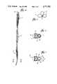
- FIG. 2is a fragmentary, elevational view in partial section in which the coupling structure of a first device (a pressure sensor) and a second device (an infusion lumen) are cooperatively configured to position the pressure sensor transducer and distal end of the infusion lumen in the same general location in the vessel;
- a first devicea pressure sensor
- a second devicean infusion lumen
- FIG. 3is a vertical sectional view taken along lines 3--3 of FIG. 2;
- FIG. 4is an elevational, fragmentary, view in partial section of an assembly in accordance with the present invention showing three devices;
- FIG. 6is a vertical sectional view taken along line 6--6 of FIG. 1;
- FIG. 7is a vertical sectional view of an alternative embodiment similar to the embodiment of FIG. 6 in which the guidewire-receiving passage through the body comprises a groove.
- FIG. 1an elongated, flexible guidewire 10 is shown which is insertable into a biological vessel.
- the guidewireis particularly adapted for cardiac catheterization and is approximately 0.014 inches (0.3 mm) in outer diameter.
- FIG. 4a plurality of diagnostic devices 11 are shown coupled to the guidewire 10.
- FIG. 1a single device 11 comprising a pressure sensor 12 is shown which is similar to Applicant's prior application Ser. No. 912,195, which is incorporated herein by reference.
- each device 11includes an elongated body 14, and elongated catheter 16 coupled to the body 14 in longitudinal alignment therewith and coupling mechanism 20 depending from the body 14.
- the body 14 of the pressure sensor 12includes an internal cavity 22 which is isolated from the biological fluid with the sensor 12 immersed in the fluid.
- An elongated, rectangular pressure member 24is mounted along one wall of the body 14 and includes a thin, flexible diaphragm 26. With the sensor 12 inserted into biological fluid the diaphragm 26 is flexed in response to the pressure of the fluid. In most cases, the cavity 22 is simply filled with ambient air so that the diaphragm 26 deforms in response to differential pressure between the biological fluid pressure and ambient air pressure.
- Strain gauges(not shown) are coupled across the diaphragm and are responsive to the flexure of the diaphragm 26. Electrical leads 28 are coupled to the strain gauges and lead through the catheter to an external electronic processing device.
- the coupling mechanism 20depends from the body 14 and defines an elongated passage 30 for slidably receiving the guidewire 10 as shown in FIG. 1.
- the diameter of the passage 30is approximately 0.016 inches so that the guidewire 10 is easily slidable therethrough.
- the largest dimension of the body 14 and coupling mechanism 20is approximately 3-4 French or slightly in excess of 1 mm.
- FIGS. 2-5 and 7a variety of alternatives and modifications are illustrated, the same numerals being applied for the structures illustrated in FIGS. 2-5 and 7 as applied to the embodiment illustrated in FIGS. 1 and 6.
- a guidewire 10is illustrated in which two different devices 11 are mounted.
- the first devicecomprises a pres sensor 12 similar to the pressure sensor 12 illustrated in FIG. 1.
- the second device in FIG. 2comprises an infusion catheter 32 which provides a working lumen having a distal opening 34.
- the pressure sensor 12has been modified in FIG. 2 in that the coupling mechanism 20 is truncated and located to depend from the distal end of the body 14. As can be seen in FIG. 2, the coupling mechanism 20 of the infusion catheter 32 is located such that the distal opening of the lumen 34 is located in the same general axial location (transverse plane of the biological vessel) as the sensor member 24 of the pressure sensor 12. It will be appreciated that two or more devices 11 may have their coupling mechanisms 20 spaced relative to their sensor portions (e.g. sensor member 24), such that the devices 11 may be positioned with the sensors in the same general transverse cross-section in the biological vessel. For example, a first pressure sensor 12 may have its coupling mechanism 20 located at its distal end (as shown in FIG.
- a second pressure sensor 12may have its coupling mechanism 20 located in a medial location, while a third pressure sensor 12 may have a coupling mechanism 20 located in a proximal position on the body 14.
- the location of the coupling mechanisms 20 on their respective pressure sensors 12permit the pressure sensors 12 to be all positioned on the guidewire 10 such that the three pressure sensor members 24 are in the same general location (transverse cross-section) in the vessel.
- the coupling mechanism 20 of the infusion catheter 32is an alternative embodiment in which the passage 30 is not a cylindrical bore as shown in FIG. 6, but instead comprises a groove 36 as shown with more clarity in FIG. 7.
- the alternative embodiment of the coupling mechanism 20comprises a pair of depending fingers 38 which define therebetween a guidewire receiving groove 36.
- the distal tips 40 of the fingers 38curl back towards one another to define a slot 42 therebetween.
- the dimension of the slot 42 defined between the distal tips 40is less than the outer diameter of the wire guide 10.
- the fingers 38comprise a flexible, resilient material such that the tips 40 can be spread apart for receiving the guidewire 10.
- FIG. 2illustrates a variation of the guidewire 10 in that a constricted fitting region 44 is illustrated.
- the guidewire 10includes a distal section which is designed for insertion into the vessel, and a proximal section which is intended to remain outside of the body during normal use.
- the fitting region 44is located in the proximal section and preferably simply comprises a constricted, cylindrical portion of the guidewire 10 having a reduced diameter.
- the diameteris approximately the dimension of the slot 42 to facilitate engagement of the coupling mechanism 20 to the guidewire 10.
- the fitting region 44simply comprises two parallel, flat regions on opposing sides of the guidewire 10, with the distance between the flat regions approximately the dimension of the slot 42.
- the fingers 38are not necessarily flexible, and are preferably not spread apart so that coupling to the guidewire 10 can only occur in fitting region 44.
- each device 11comprises a pressure sensor 12 identical to the pressure sensor 12 illustrated in FIG. 1.
- the pressure sensors 12are radially mounted about the guidewire 10.
- the respective catheter 16 of each sensor 12trails the respective body 14 with each catheter 16 generally longitudinally aligned and juxtaposed adjacent the guidewire 10.
- the devices 11are longitudinally spaced along the guidewire 10 and would be useful, for example, in determining a pressure gradient along a longitudinal region of the vessel.
- the method of the present inventioncontemplates analyzing in vivo a biological fluid in a region of a biological fluid-carrying vessel.
- a hypothetical coronary angioplasty procedurewill be described in which the stenosed coronary artery is located in the arterial tree past the left coronary ostium.
- such an angioplasty proceduremight involve inserting a guiding catheter (7-8 French Sheath) through the femoral artery approach as is well known in the art.
- the guidewireis advanced to a region close to the root of the ascending aortic arch.
- several devices 11are coupled to the guidewire 10 to assist in advancement and visualization of the position of the guidewire 10.
- the first device 11may comprise a angioplasty dilating balloon in combination with a velocity-determining sensor, similar to that described in U.S. Pat. No. 4,665,925 (incorporated herein by reference).
- the guidewire 10itself might include a velocity-determining sensor such as described in Applicant's co-pending application Ser. No. 081,308 (incorporated here in by reference).
- the first device 11would include an angioplasty balloon mounted to the body 14 with the pneumatic lumen running through the catheter 16.
- a Doppler crystalwould be fitted to the distal end of the body 14 with the electrical leads running through the catheter 16.
- the streamline, low profile configuration of the body 14aides in manipulating the device 11 past constrictions in the approach.
- the guidewire 10is advanced to intubate the left coronary ostium using a conventional method such as the Judkins technique.
- the distal tip of the guidewire 10is then manipulated and steered into the coronary artery of interest, with the stenosis identified using a variety of techniques, such as the arteriogram, fluid velocity measurements, and perhaps fluid pressure measurements.
- the angioplasty ballooncan be inflated to distend the stenosis and the efficacy of the treatment analyzed using one or more of the devices 11.
- the first or distal device 11 and guidewire 10are left in position in the region of the coronary artery of interest and the second device 11 is to be exchanged.
- the second and subsequent devices 11can be withdrawn and once outside the body are easily slid from the guidewire 10.
- valvuloplastyhas become a common procedure for treating stenosis across a heart valve.
- the guidewire 10is advanced into the ventricle with a pressure sensor 12 advanced into the ventricle.
- a second device 11, comprising an angioplasty balloon catheter,is advanced over the guidewire 10 and positioned in the region of the heart valve.
- another pressure sensor 12might be advanced behind the balloon catheter.
- the balloonis expanded and the aortic valve distended to relieve the stenosis.
- urinary incontinencemight be diagnosed with the guidewire 10 advanced through the urethra into the bladder and a first pressure sensor 12 advanced along the guidewire 10 into the bladder.
- a second pressure sensor 12might then be advanced along the guidewire 10 into the urethra and bladder pressure and urethra pressure monitored.
- Other devices 11might similarly be advanced for monitoring temperature, pH or velocity of the urine.
- Still another applicationmight involve diagnosis of acidity and peristaltic action of the digestive tract.
- the guidewire 10would be advanced past the esophageal valve and the distal end positioned in the stomach.
- a first device 11, comprising a pH sensor and perhaps a pressure sensor 12is advanced through the valve into the stomach to monitor the acidity and pressure in the stomach.
- a second pressure sensor 12is then inserted into the esophageal tract above the esophageal valve.
- the two pressure sensorscould monitor the efficacy of the esophageal valve.
- sensorssuch as pressure sensors, velocity measuring sensors, pH and temperature probes, etc. can be expensive. Under current technology, all such sensors or therapeutic devices must be incorporated into a single catheter which can be very expensive. In most cases, it is necessary that such a catheter have a working lumen to allow access to the fluid vessel for injecting contrast media, monitoring pressure, or to perform similar functions. Such a working lumen is, of course, contaminated with the blood or other biological fluid and must be thoroughly cleaned if the multiple device catheter is to be reused. In view of the contamination and difficulty in cleaning, there is a strong bias towards disposable catheters. However, such a multiple sensor catheter is very expensive and not readily amenable to manufacturing as a disposable item. Oftentimes if such a multiple sensor catheter is produced, the sensors are manufactured in such a fashion to reduce cost, but offer a low fidelity instrument.
- the expensive devices 11such as the sensors
- the infusion catheter 32would be a low cost disposable item in view of the difficulty of adequately and efficiently cleaning the lumen of the infusion catheter 32.
- the lumen of the catheter 16is isolated from the fluid, so that only the external surfaces of the catheter 16 and body 14 must be cleaned--a relatively simple task.
- the relatively short passage 30 of the coupling mechanism 20is readily cleaned, and in the alternative embodiment (FIGS. 2, 3, 7) comprising the groove 36, is especially easily cleaned for reuse.
- the high fidelity sensor-type devices 11can be designed for reuse and the high cost of such devices 11 amortized over a number of procedures and a number of patients.
- the method, pressure sensor, assembly and system of the present inventionpresents a marked practical advance over conventional catheterization methods in more efficiently diagnosing and treating in vivo.
Landscapes
- Health & Medical Sciences (AREA)
- Life Sciences & Earth Sciences (AREA)
- Public Health (AREA)
- Biophysics (AREA)
- Physics & Mathematics (AREA)
- Engineering & Computer Science (AREA)
- Biomedical Technology (AREA)
- Heart & Thoracic Surgery (AREA)
- Veterinary Medicine (AREA)
- Animal Behavior & Ethology (AREA)
- General Health & Medical Sciences (AREA)
- Anesthesiology (AREA)
- Hematology (AREA)
- Pulmonology (AREA)
- Optics & Photonics (AREA)
- Pathology (AREA)
- Medical Informatics (AREA)
- Molecular Biology (AREA)
- Surgery (AREA)
- Media Introduction/Drainage Providing Device (AREA)
- Measuring Pulse, Heart Rate, Blood Pressure Or Blood Flow (AREA)
Abstract
Description
Claims (17)
Priority Applications (10)
| Application Number | Priority Date | Filing Date | Title |
|---|---|---|---|
| US06/931,273US4771782A (en) | 1986-11-14 | 1986-11-14 | Method and assembly for introducing multiple catheters into a biological vessel |
| US07/119,616US4850358A (en) | 1986-11-14 | 1987-11-12 | Method and assembly for introducing multiple devices into a biological vessel |
| AU83357/87AAU8335787A (en) | 1986-11-14 | 1987-11-13 | Assembly for introducing multiple catheters |
| EP87908057AEP0332649B1 (en) | 1986-11-14 | 1987-11-13 | Assembly for introducing multiple catheters |
| DE8787908057TDE3784074T2 (en) | 1986-11-14 | 1987-11-13 | DEVICE FOR IMPORTING SEVERAL CATHETERS. |
| AT87908057TATE85228T1 (en) | 1986-11-14 | 1987-11-13 | DEVICE FOR INSERTING MULTIPLE CATHETER. |
| JP63500300AJP2602938B2 (en) | 1986-11-14 | 1987-11-13 | Assembly and pressure sensor for engaging an elongated, flexible and operable guidewire |
| PCT/US1987/002972WO1988003422A1 (en) | 1986-11-14 | 1987-11-13 | Assembly for introducing multiple catheters |
| US07/286,475US4966148A (en) | 1986-11-14 | 1988-12-19 | Assembly for positioning diagnostic devices in a biological vessel |
| US07/286,480US5046497A (en) | 1986-11-14 | 1988-12-19 | Structure for coupling a guidewire and a catheter |
Applications Claiming Priority (1)
| Application Number | Priority Date | Filing Date | Title |
|---|---|---|---|
| US06/931,273US4771782A (en) | 1986-11-14 | 1986-11-14 | Method and assembly for introducing multiple catheters into a biological vessel |
Related Child Applications (1)
| Application Number | Title | Priority Date | Filing Date |
|---|---|---|---|
| US07/119,616Continuation-In-PartUS4850358A (en) | 1986-11-14 | 1987-11-12 | Method and assembly for introducing multiple devices into a biological vessel |
Publications (1)
| Publication Number | Publication Date |
|---|---|
| US4771782Atrue US4771782A (en) | 1988-09-20 |
Family
ID=25460504
Family Applications (1)
| Application Number | Title | Priority Date | Filing Date |
|---|---|---|---|
| US06/931,273Expired - LifetimeUS4771782A (en) | 1986-11-14 | 1986-11-14 | Method and assembly for introducing multiple catheters into a biological vessel |
Country Status (4)
| Country | Link |
|---|---|
| US (1) | US4771782A (en) |
| EP (1) | EP0332649B1 (en) |
| AU (1) | AU8335787A (en) |
| WO (1) | WO1988003422A1 (en) |
Cited By (150)
| Publication number | Priority date | Publication date | Assignee | Title |
|---|---|---|---|---|
| WO1989011292A1 (en)* | 1988-05-23 | 1989-11-30 | Georgetown University | Liposome-encapsulated vinca alkoaloids and their use in combatting tumors |
| US4917097A (en)* | 1987-10-27 | 1990-04-17 | Endosonics Corporation | Apparatus and method for imaging small cavities |
| US4966148A (en)* | 1986-11-14 | 1990-10-30 | Millar Instruments, Inc. | Assembly for positioning diagnostic devices in a biological vessel |
| US5038789A (en)* | 1989-09-28 | 1991-08-13 | Frazin Leon J | Method and device for doppler-guided retrograde catheterization |
| US5046497A (en)* | 1986-11-14 | 1991-09-10 | Millar Instruments, Inc. | Structure for coupling a guidewire and a catheter |
| US5057120A (en)* | 1988-10-27 | 1991-10-15 | Farcot Jean Christian | Apparatus for the performance of an angioplasty of long duration |
| US5131407A (en)* | 1989-12-01 | 1992-07-21 | C. R. Bard, Inc. | Guidewire with tracking member and catheter exchange system |
| US5190045A (en)* | 1989-09-28 | 1993-03-02 | Frazin Leon J | Method and device for doppler-guided and imaged retrograde catheterization |
| US5220924A (en)* | 1989-09-28 | 1993-06-22 | Frazin Leon J | Doppler-guided retrograde catheterization using transducer equipped guide wire |
| US5267958A (en)* | 1992-03-30 | 1993-12-07 | Medtronic, Inc. | Exchange catheter having exterior guide wire loops |
| US5368037A (en)* | 1993-02-01 | 1994-11-29 | Endosonics Corporation | Ultrasound catheter |
| US5368567A (en)* | 1992-07-27 | 1994-11-29 | Schneider (Usa) Inc. | Dilatation balloon catheter with infusion lumen |
| US5372592A (en)* | 1992-06-22 | 1994-12-13 | C. R. Bard, Inc. | Method and device for preparing catheters prior to use |
| US5395332A (en)* | 1990-08-28 | 1995-03-07 | Scimed Life Systems, Inc. | Intravascualr catheter with distal tip guide wire lumen |
| US5431628A (en)* | 1992-09-29 | 1995-07-11 | Millar Instruments, Inc. | Pressure-sensing diagnostic catheter |
| US5571087A (en)* | 1992-02-10 | 1996-11-05 | Scimed Life Systems, Inc. | Intravascular catheter with distal tip guide wire lumen |
| US5603327A (en)* | 1993-02-01 | 1997-02-18 | Endosonics Corporation | Ultrasound catheter probe |
| EP0756851A3 (en)* | 1995-08-03 | 1997-04-09 | United States Surgical Corp | Vascular hole closure |
| US5626600A (en)* | 1987-01-06 | 1997-05-06 | Advanced Cardiovascular Systems, Inc. | Reinforced balloon dilatation catheter with slitted exchange sleeve and method |
| US5658251A (en)* | 1988-02-29 | 1997-08-19 | Scimed Life Systems, Inc. | Intravascular catheter with distal guide wire lumen and transition member |
| US5690642A (en)* | 1996-01-18 | 1997-11-25 | Cook Incorporated | Rapid exchange stent delivery balloon catheter |
| WO1998017179A1 (en)* | 1996-10-17 | 1998-04-30 | Malachy Gleeson | Device for closure of a puncture wound |
| US5902248A (en)* | 1996-11-06 | 1999-05-11 | Millar Instruments, Inc. | Reduced size catheter tip measurement device |
| US6004291A (en)* | 1988-02-29 | 1999-12-21 | Scimed Life Systems, Inc. | Intravascular catheter with distal guide wire lumen and transition |
| US6162182A (en)* | 1998-08-26 | 2000-12-19 | Becton, Dickinson And Company | Pressure tip cannula |
| WO2001068177A1 (en)* | 2000-03-10 | 2001-09-20 | Kensey Nash Corporation | Device for connecting a catheter onto a guide-wire |
| US6394986B1 (en) | 1999-11-06 | 2002-05-28 | Millar Instruments, Inc. | Pressure sensing module for a catheter pressure transducer |
| US20020198497A1 (en)* | 2000-03-10 | 2002-12-26 | Kensey Nash Corporation | Tool for facilitating the connecting of a catheter or other tubular member onto a guide-wire without access to the ends of the guide-wire |
| US20030040674A1 (en)* | 1994-09-02 | 2003-02-27 | Jomed, Inc. | Ultra miniature pressure sensor |
| US20030055483A1 (en)* | 2001-08-23 | 2003-03-20 | Gumm Darrell C. | Rotating stent delivery system for side branch access and protection and method of using same |
| US6546787B1 (en) | 1999-03-25 | 2003-04-15 | Regents Of The University Of Minnesota | Means and method for modeling and treating specific tissue structures |
| US6582452B2 (en) | 2000-09-08 | 2003-06-24 | James Coleman | Surgical stapler |
| US20040006263A1 (en)* | 2002-06-03 | 2004-01-08 | Anderson Edward J. | Noninvasive detection of a physiologic parameter within a body tissue of a patient |
| US6685712B2 (en) | 2000-09-08 | 2004-02-03 | Christy Cummins | Surgical micro-stapling instrument |
| US20040028502A1 (en)* | 2001-06-07 | 2004-02-12 | Christy Cummins | Surgical staple |
| US6706055B2 (en) | 2001-04-03 | 2004-03-16 | Medtronic Ave Inc. | Guidewire apparatus for temporary distal embolic protection |
| US20040054287A1 (en)* | 2002-08-29 | 2004-03-18 | Stephens Douglas Neil | Ultrasonic imaging devices and methods of fabrication |
| US20040236355A1 (en)* | 2001-08-09 | 2004-11-25 | Thomas Anthony | Surgical stapling device |
| US20040249391A1 (en)* | 2001-08-09 | 2004-12-09 | Christy Cummins | Surgical stapling device and method |
| US20050113798A1 (en)* | 2000-07-21 | 2005-05-26 | Slater Charles R. | Methods and apparatus for treating the interior of a blood vessel |
| US20050256537A1 (en)* | 2002-07-03 | 2005-11-17 | Christy Cummins | Surgical stapling device |
| US20050268725A1 (en)* | 2004-06-04 | 2005-12-08 | Radi Medical Systems Ab | Sensor and guide wire assembly |
| US20060036307A1 (en)* | 2004-08-16 | 2006-02-16 | Cardiac Pacemakers, Inc. | Lead assembly and methods including a push tube |
| US20060074318A1 (en)* | 2004-09-27 | 2006-04-06 | Masood Ahmed | Combination sensor guidewire and methods of use |
| US20060133715A1 (en)* | 2004-12-22 | 2006-06-22 | Claude Belleville | Fiber optic pressure sensor for catheter use |
| US20070016071A1 (en)* | 1993-02-01 | 2007-01-18 | Volcano Corporation | Ultrasound transducer assembly |
| US20070208302A1 (en)* | 2006-01-26 | 2007-09-06 | Webster Mark W | Deflection control catheters, support catheters and methods of use |
| US20080194973A1 (en)* | 2005-09-13 | 2008-08-14 | Imam Farhad B | Light-guided transluminal catheter |
| US20080306453A1 (en)* | 2007-06-06 | 2008-12-11 | Cook Incorporated | Coupling wire guide and method for making same |
| US7494468B2 (en) | 1999-10-05 | 2009-02-24 | Omnisonics Medical Technologies, Inc. | Ultrasonic medical device operating in a transverse mode |
| US7503895B2 (en) | 1999-10-05 | 2009-03-17 | Omnisonics Medical Technologies, Inc. | Ultrasonic device for tissue ablation and sheath for use therewith |
| USD611144S1 (en) | 2006-06-28 | 2010-03-02 | Abbott Laboratories | Apparatus for delivering a closure element |
| US20100228112A1 (en)* | 2007-10-26 | 2010-09-09 | St. Jude Medical Systems Ab | Sensor guide wire with micro-cable winding |
| US7794414B2 (en) | 2004-02-09 | 2010-09-14 | Emigrant Bank, N.A. | Apparatus and method for an ultrasonic medical device operating in torsional and transverse modes |
| US20100234698A1 (en)* | 2008-09-11 | 2010-09-16 | Acist Medical Systems, Inc. | Physiological sensor delivery device and method |
| US7806910B2 (en) | 2002-11-26 | 2010-10-05 | Abbott Laboratories | Multi-element biased suture clip |
| US7806904B2 (en) | 2000-12-07 | 2010-10-05 | Integrated Vascular Systems, Inc. | Closure device |
| US7819895B2 (en) | 2000-01-05 | 2010-10-26 | Integrated Vascular Systems, Inc. | Vascular sheath with bioabsorbable puncture site closure apparatus and methods of use |
| US7828817B2 (en) | 2000-01-05 | 2010-11-09 | Integrated Vascular Systems, Inc. | Apparatus and methods for delivering a closure device |
| US7841502B2 (en) | 2007-12-18 | 2010-11-30 | Abbott Laboratories | Modular clip applier |
| US7842068B2 (en) | 2000-12-07 | 2010-11-30 | Integrated Vascular Systems, Inc. | Apparatus and methods for providing tactile feedback while delivering a closure device |
| US7850709B2 (en) | 2002-06-04 | 2010-12-14 | Abbott Vascular Inc. | Blood vessel closure clip and delivery device |
| US7850797B2 (en) | 2002-12-31 | 2010-12-14 | Integrated Vascular Systems, Inc. | Methods for manufacturing a clip and clip |
| US7867249B2 (en) | 2003-01-30 | 2011-01-11 | Integrated Vascular Systems, Inc. | Clip applier and methods of use |
| US7879071B2 (en) | 2000-12-07 | 2011-02-01 | Integrated Vascular Systems, Inc. | Closure device and methods for making and using them |
| US20110066047A1 (en)* | 2009-03-17 | 2011-03-17 | Claude Belleville | Eccentric pressure catheter with guidewire compatibility |
| US7931669B2 (en) | 2000-01-05 | 2011-04-26 | Integrated Vascular Systems, Inc. | Integrated vascular device with puncture site closure component and sealant and methods of use |
| US20110144671A1 (en)* | 2009-06-18 | 2011-06-16 | Cardiovascular Systems, Inc. | Atherectomy device, system and method having a bi-directional distal expandable ablation element |
| US20110152823A1 (en)* | 2009-12-21 | 2011-06-23 | Acist Medical Systems, Inc. | Thrombus removal device and system |
| US8007512B2 (en) | 2002-02-21 | 2011-08-30 | Integrated Vascular Systems, Inc. | Plunger apparatus and methods for delivering a closure device |
| US8048108B2 (en) | 2005-08-24 | 2011-11-01 | Abbott Vascular Inc. | Vascular closure methods and apparatuses |
| US8078261B2 (en) | 2005-09-13 | 2011-12-13 | Children's Medical Center Corporation | Light-guided transluminal catheter |
| US8202294B2 (en) | 2003-01-30 | 2012-06-19 | Integrated Vascular Systems, Inc. | Clip applier and methods of use |
| US8202293B2 (en) | 2003-01-30 | 2012-06-19 | Integrated Vascular Systems, Inc. | Clip applier and methods of use |
| US8226681B2 (en) | 2007-06-25 | 2012-07-24 | Abbott Laboratories | Methods, devices, and apparatus for managing access through tissue |
| US20120265238A1 (en)* | 1999-07-30 | 2012-10-18 | Incept, Llc | Vascular device for emboli, thrombus and foreign body removal and methods of use |
| US8303624B2 (en) | 2010-03-15 | 2012-11-06 | Abbott Cardiovascular Systems, Inc. | Bioabsorbable plug |
| US8313497B2 (en) | 2005-07-01 | 2012-11-20 | Abbott Laboratories | Clip applier and methods of use |
| US8323312B2 (en) | 2008-12-22 | 2012-12-04 | Abbott Laboratories | Closure device |
| US8398656B2 (en) | 2003-01-30 | 2013-03-19 | Integrated Vascular Systems, Inc. | Clip applier and methods of use |
| US8398676B2 (en) | 2008-10-30 | 2013-03-19 | Abbott Vascular Inc. | Closure device |
| US8556932B2 (en) | 2011-05-19 | 2013-10-15 | Abbott Cardiovascular Systems, Inc. | Collapsible plug for tissue closure |
| US8556930B2 (en) | 2006-06-28 | 2013-10-15 | Abbott Laboratories | Vessel closure device |
| US8590760B2 (en) | 2004-05-25 | 2013-11-26 | Abbott Vascular Inc. | Surgical stapler |
| US8603116B2 (en) | 2010-08-04 | 2013-12-10 | Abbott Cardiovascular Systems, Inc. | Closure device with long tines |
| US8617184B2 (en) | 2011-02-15 | 2013-12-31 | Abbott Cardiovascular Systems, Inc. | Vessel closure system |
| US8672953B2 (en) | 2007-12-17 | 2014-03-18 | Abbott Laboratories | Tissue closure system and methods of use |
| US8690910B2 (en) | 2000-12-07 | 2014-04-08 | Integrated Vascular Systems, Inc. | Closure device and methods for making and using them |
| US8758400B2 (en) | 2000-01-05 | 2014-06-24 | Integrated Vascular Systems, Inc. | Closure system and methods of use |
| US8758399B2 (en) | 2010-08-02 | 2014-06-24 | Abbott Cardiovascular Systems, Inc. | Expandable bioabsorbable plug apparatus and method |
| US8758398B2 (en) | 2006-09-08 | 2014-06-24 | Integrated Vascular Systems, Inc. | Apparatus and method for delivering a closure element |
| US8790359B2 (en) | 1999-10-05 | 2014-07-29 | Cybersonics, Inc. | Medical systems and related methods |
| US8808310B2 (en) | 2006-04-20 | 2014-08-19 | Integrated Vascular Systems, Inc. | Resettable clip applier and reset tools |
| US8821534B2 (en) | 2010-12-06 | 2014-09-02 | Integrated Vascular Systems, Inc. | Clip applier having improved hemostasis and methods of use |
| US8858594B2 (en) | 2008-12-22 | 2014-10-14 | Abbott Laboratories | Curved closure device |
| US8893947B2 (en) | 2007-12-17 | 2014-11-25 | Abbott Laboratories | Clip applier and methods of use |
| US8905937B2 (en) | 2009-02-26 | 2014-12-09 | Integrated Vascular Systems, Inc. | Methods and apparatus for locating a surface of a body lumen |
| US8920442B2 (en) | 2005-08-24 | 2014-12-30 | Abbott Vascular Inc. | Vascular opening edge eversion methods and apparatuses |
| US8926633B2 (en) | 2005-06-24 | 2015-01-06 | Abbott Laboratories | Apparatus and method for delivering a closure element |
| US9089674B2 (en) | 2000-10-06 | 2015-07-28 | Integrated Vascular Systems, Inc. | Apparatus and methods for positioning a vascular sheath |
| US9089311B2 (en) | 2009-01-09 | 2015-07-28 | Abbott Vascular Inc. | Vessel closure devices and methods |
| US9149276B2 (en) | 2011-03-21 | 2015-10-06 | Abbott Cardiovascular Systems, Inc. | Clip and deployment apparatus for tissue closure |
| US9173644B2 (en) | 2009-01-09 | 2015-11-03 | Abbott Vascular Inc. | Closure devices, systems, and methods |
| US9282965B2 (en) | 2008-05-16 | 2016-03-15 | Abbott Laboratories | Apparatus and methods for engaging tissue |
| US9314230B2 (en) | 2009-01-09 | 2016-04-19 | Abbott Vascular Inc. | Closure device with rapidly eroding anchor |
| US9332976B2 (en) | 2011-11-30 | 2016-05-10 | Abbott Cardiovascular Systems, Inc. | Tissue closure device |
| US9364209B2 (en) | 2012-12-21 | 2016-06-14 | Abbott Cardiovascular Systems, Inc. | Articulating suturing device |
| US9414824B2 (en) | 2009-01-16 | 2016-08-16 | Abbott Vascular Inc. | Closure devices, systems, and methods |
| US9414820B2 (en) | 2009-01-09 | 2016-08-16 | Abbott Vascular Inc. | Closure devices, systems, and methods |
| US9429713B2 (en) | 2014-04-17 | 2016-08-30 | Boston Scientific Scimed, Inc. | Self-cleaning optical connector |
| US9456811B2 (en) | 2005-08-24 | 2016-10-04 | Abbott Vascular Inc. | Vascular closure methods and apparatuses |
| US9486191B2 (en) | 2009-01-09 | 2016-11-08 | Abbott Vascular, Inc. | Closure devices |
| US9579091B2 (en) | 2000-01-05 | 2017-02-28 | Integrated Vascular Systems, Inc. | Closure system and methods of use |
| US9585647B2 (en) | 2009-08-26 | 2017-03-07 | Abbott Laboratories | Medical device for repairing a fistula |
| US9775567B2 (en) | 2011-05-11 | 2017-10-03 | Acist Medical Systems, Inc. | Intravascular sensing method and system |
| US9775523B2 (en) | 2013-10-14 | 2017-10-03 | Boston Scientific Scimed, Inc. | Pressure sensing guidewire and methods for calculating fractional flow reserve |
| US9782129B2 (en) | 2014-08-01 | 2017-10-10 | Boston Scientific Scimed, Inc. | Pressure sensing guidewires |
| US9795307B2 (en) | 2014-12-05 | 2017-10-24 | Boston Scientific Scimed, Inc. | Pressure sensing guidewires |
| WO2017207931A1 (en) | 2016-06-01 | 2017-12-07 | Hexacath | Device forming an infusion catheter for treating at least one partial or total obstruction in a passage, such as a body passage |
| US9877660B2 (en) | 2013-11-14 | 2018-01-30 | Medtronic Vascular Galway | Systems and methods for determining fractional flow reserve without adenosine or other pharmalogical agent |
| US9913585B2 (en) | 2014-01-15 | 2018-03-13 | Medtronic Vascular, Inc. | Catheter for providing vascular pressure measurements |
| US10028666B2 (en) | 2013-03-15 | 2018-07-24 | Boston Scientific Scimed, Inc. | Pressure sensing guidewire |
| US10130269B2 (en) | 2013-11-14 | 2018-11-20 | Medtronic Vascular, Inc | Dual lumen catheter for providing a vascular pressure measurement |
| US10194812B2 (en) | 2014-12-12 | 2019-02-05 | Medtronic Vascular, Inc. | System and method of integrating a fractional flow reserve device with a conventional hemodynamic monitoring system |
| US10201284B2 (en) | 2014-06-16 | 2019-02-12 | Medtronic Vascular Inc. | Pressure measuring catheter having reduced error from bending stresses |
| US10244951B2 (en) | 2014-06-10 | 2019-04-02 | Acist Medical Systems, Inc. | Physiological sensor delivery device and method |
| US10278594B2 (en) | 2014-06-04 | 2019-05-07 | Boston Scientific Scimed, Inc. | Pressure sensing guidewire systems with reduced pressure offsets |
| US10499820B2 (en) | 2013-05-22 | 2019-12-10 | Boston Scientific Scimed, Inc. | Pressure sensing guidewire systems including an optical connector cable |
| US10582860B2 (en) | 2012-08-27 | 2020-03-10 | Boston Scientific Scimed, Inc. | Pressure-sensing medical devices and medical device systems |
| US10646122B2 (en) | 2017-04-28 | 2020-05-12 | Medtronic Vascular, Inc. | FFR catheter with covered distal pressure sensor and method of manufacture |
| US10702162B2 (en) | 2010-11-09 | 2020-07-07 | Opsens Inc. | Guidewire with internal pressure sensor |
| US10743774B2 (en) | 2018-04-20 | 2020-08-18 | Acist Medical Systems, Inc. | Assessment of a vessel |
| US10835182B2 (en) | 2013-08-14 | 2020-11-17 | Boston Scientific Scimed, Inc. | Medical device systems including an optical fiber with a tapered core |
| CN112292074A (en)* | 2018-04-06 | 2021-01-29 | 波士顿科学国际有限公司 | Medical device with pressure sensor |
| US10932679B2 (en) | 2014-03-18 | 2021-03-02 | Boston Scientific Scimed, Inc. | Pressure sensing guidewires and methods of use |
| US10973418B2 (en) | 2014-06-16 | 2021-04-13 | Medtronic Vascular, Inc. | Microcatheter sensor design for minimizing profile and impact of wire strain on sensor |
| US11058307B2 (en) | 2016-02-23 | 2021-07-13 | Boston Scientific Scimed, Inc. | Pressure sensing guidewire systems including an optical connector cable |
| US11076765B2 (en) | 2013-07-26 | 2021-08-03 | Boston Scientific Scimed, Inc. | FFR sensor head design that minimizes stress induced pressure offsets |
| US11185244B2 (en) | 2018-08-13 | 2021-11-30 | Medtronic Vascular, Inc. | FFR catheter with suspended pressure sensor |
| US11219741B2 (en) | 2017-08-09 | 2022-01-11 | Medtronic Vascular, Inc. | Collapsible catheter and method for calculating fractional flow reserve |
| US11235124B2 (en) | 2017-08-09 | 2022-02-01 | Medtronic Vascular, Inc. | Collapsible catheter and method for calculating fractional flow reserve |
| US11272850B2 (en) | 2016-08-09 | 2022-03-15 | Medtronic Vascular, Inc. | Catheter and method for calculating fractional flow reserve |
| US11311196B2 (en) | 2018-02-23 | 2022-04-26 | Boston Scientific Scimed, Inc. | Methods for assessing a vessel with sequential physiological measurements |
| US11330994B2 (en) | 2017-03-08 | 2022-05-17 | Medtronic Vascular, Inc. | Reduced profile FFR catheter |
| US11330989B2 (en) | 2014-06-16 | 2022-05-17 | Medtronic Vascular, Inc. | Microcatheter sensor design for mounting sensor to minimize induced strain |
| US11369547B2 (en)* | 2018-12-28 | 2022-06-28 | SaiNath Intelleotual Properties, LLC | Catheter with balloon valve |
| US11564581B2 (en) | 2017-08-03 | 2023-01-31 | Boston Scientific Scimed, Inc. | Methods for assessing fractional flow reserve |
| US11666232B2 (en) | 2018-04-18 | 2023-06-06 | Boston Scientific Scimed, Inc. | Methods for assessing a vessel with sequential physiological measurements |
| US11850073B2 (en) | 2018-03-23 | 2023-12-26 | Boston Scientific Scimed, Inc. | Medical device with pressure sensor |
| US12087000B2 (en) | 2021-03-05 | 2024-09-10 | Boston Scientific Scimed, Inc. | Systems and methods for vascular image co-registration |
Families Citing this family (3)
| Publication number | Priority date | Publication date | Assignee | Title |
|---|---|---|---|---|
| ES2049204T3 (en)* | 1989-01-30 | 1994-07-16 | Bard Inc C R | RAPIDLY CHANGEABLE CORONARY CATHETER. |
| US5728067A (en)* | 1989-01-30 | 1998-03-17 | C. R. Bard, Inc. | Rapidly exchangeable coronary catheter |
| EP3222206A1 (en)* | 2016-03-23 | 2017-09-27 | ETH Zurich | Method for the manufacturing of a carrying device, carrying device, system for detection of a physical parameter and method for detection of a physical parameter |
Citations (2)
| Publication number | Priority date | Publication date | Assignee | Title |
|---|---|---|---|---|
| US3038465A (en)* | 1958-08-07 | 1962-06-12 | Allard Emmanuel Marie Lucien | Micromanometer particularly adapted for use with a cardiac catheter |
| US4456013A (en)* | 1981-09-08 | 1984-06-26 | Brown University Research Foundation | Catheter |
Family Cites Families (7)
| Publication number | Priority date | Publication date | Assignee | Title |
|---|---|---|---|---|
| US1747407A (en)* | 1928-07-20 | 1930-02-18 | Reinhold H Wappler | Catheterizing instrument |
| US3853130A (en)* | 1973-12-04 | 1974-12-10 | D Sheridan | Sterile handling catheter assemblies |
| US3995623A (en)* | 1974-12-23 | 1976-12-07 | American Hospital Supply Corporation | Multipurpose flow-directed catheter |
| CH616337A5 (en)* | 1977-10-21 | 1980-03-31 | Schneider Medintag Ag | |
| US4545390A (en)* | 1982-09-22 | 1985-10-08 | C. R. Bard, Inc. | Steerable guide wire for balloon dilatation procedure |
| US4651751A (en)* | 1982-10-14 | 1987-03-24 | American Hospital Supply Corporation | Guiding catheter and method of use |
| US4613323A (en)* | 1984-11-19 | 1986-09-23 | University Of Kentucky Research Foundation | Multiple function intubation apparatus and method |
- 1986
- 1986-11-14USUS06/931,273patent/US4771782A/ennot_activeExpired - Lifetime
- 1987
- 1987-11-13EPEP87908057Apatent/EP0332649B1/ennot_activeExpired - Lifetime
- 1987-11-13WOPCT/US1987/002972patent/WO1988003422A1/enactiveIP Right Grant
- 1987-11-13AUAU83357/87Apatent/AU8335787A/ennot_activeAbandoned
Patent Citations (2)
| Publication number | Priority date | Publication date | Assignee | Title |
|---|---|---|---|---|
| US3038465A (en)* | 1958-08-07 | 1962-06-12 | Allard Emmanuel Marie Lucien | Micromanometer particularly adapted for use with a cardiac catheter |
| US4456013A (en)* | 1981-09-08 | 1984-06-26 | Brown University Research Foundation | Catheter |
Non-Patent Citations (2)
| Title |
|---|
| Product brochure of Schneider Medintag AG, entitled: "Monorail-Bonzel Coronary Dilation System". |
| Product brochure of Schneider Medintag AG, entitled: Monorail Bonzel Coronary Dilation System .* |
Cited By (284)
| Publication number | Priority date | Publication date | Assignee | Title |
|---|---|---|---|---|
| US4966148A (en)* | 1986-11-14 | 1990-10-30 | Millar Instruments, Inc. | Assembly for positioning diagnostic devices in a biological vessel |
| US5046497A (en)* | 1986-11-14 | 1991-09-10 | Millar Instruments, Inc. | Structure for coupling a guidewire and a catheter |
| US5626600A (en)* | 1987-01-06 | 1997-05-06 | Advanced Cardiovascular Systems, Inc. | Reinforced balloon dilatation catheter with slitted exchange sleeve and method |
| US4917097A (en)* | 1987-10-27 | 1990-04-17 | Endosonics Corporation | Apparatus and method for imaging small cavities |
| US5658251A (en)* | 1988-02-29 | 1997-08-19 | Scimed Life Systems, Inc. | Intravascular catheter with distal guide wire lumen and transition member |
| US5720724A (en)* | 1988-02-29 | 1998-02-24 | Scimed Life Systems, Inc. | Intravascular catheter with distal guide wire lumen and transition member |
| US6004291A (en)* | 1988-02-29 | 1999-12-21 | Scimed Life Systems, Inc. | Intravascular catheter with distal guide wire lumen and transition |
| WO1989011292A1 (en)* | 1988-05-23 | 1989-11-30 | Georgetown University | Liposome-encapsulated vinca alkoaloids and their use in combatting tumors |
| US5057120A (en)* | 1988-10-27 | 1991-10-15 | Farcot Jean Christian | Apparatus for the performance of an angioplasty of long duration |
| US5220924A (en)* | 1989-09-28 | 1993-06-22 | Frazin Leon J | Doppler-guided retrograde catheterization using transducer equipped guide wire |
| US5190045A (en)* | 1989-09-28 | 1993-03-02 | Frazin Leon J | Method and device for doppler-guided and imaged retrograde catheterization |
| US5038789A (en)* | 1989-09-28 | 1991-08-13 | Frazin Leon J | Method and device for doppler-guided retrograde catheterization |
| US5131407A (en)* | 1989-12-01 | 1992-07-21 | C. R. Bard, Inc. | Guidewire with tracking member and catheter exchange system |
| US5395332A (en)* | 1990-08-28 | 1995-03-07 | Scimed Life Systems, Inc. | Intravascualr catheter with distal tip guide wire lumen |
| US5571087A (en)* | 1992-02-10 | 1996-11-05 | Scimed Life Systems, Inc. | Intravascular catheter with distal tip guide wire lumen |
| US5921958A (en)* | 1992-02-10 | 1999-07-13 | Scimed Life Systems, Inc. | Intravascular catheter with distal tip guide wire lumen |
| US5267958A (en)* | 1992-03-30 | 1993-12-07 | Medtronic, Inc. | Exchange catheter having exterior guide wire loops |
| US5372592A (en)* | 1992-06-22 | 1994-12-13 | C. R. Bard, Inc. | Method and device for preparing catheters prior to use |
| US5368567A (en)* | 1992-07-27 | 1994-11-29 | Schneider (Usa) Inc. | Dilatation balloon catheter with infusion lumen |
| US5431628A (en)* | 1992-09-29 | 1995-07-11 | Millar Instruments, Inc. | Pressure-sensing diagnostic catheter |
| US5938615A (en)* | 1993-02-01 | 1999-08-17 | Endosonics Corporation | Ultrasound catheter probe |
| US6123673A (en)* | 1993-02-01 | 2000-09-26 | Endosonics Corporation | Method of making an ultrasound transducer assembly |
| US20060058681A1 (en)* | 1993-02-01 | 2006-03-16 | Volcano Corporation | Ultrasound transducer assembly |
| US5779644A (en)* | 1993-02-01 | 1998-07-14 | Endosonics Coporation | Ultrasound catheter probe |
| US20070016071A1 (en)* | 1993-02-01 | 2007-01-18 | Volcano Corporation | Ultrasound transducer assembly |
| US5368037A (en)* | 1993-02-01 | 1994-11-29 | Endosonics Corporation | Ultrasound catheter |
| US6283920B1 (en) | 1993-02-01 | 2001-09-04 | Endosonics Corporation | Ultrasound transducer assembly |
| US6962567B2 (en) | 1993-02-01 | 2005-11-08 | Volcano Therapeutics, Inc. | Ultrasound transducer assembly |
| US5603327A (en)* | 1993-02-01 | 1997-02-18 | Endosonics Corporation | Ultrasound catheter probe |
| US20030040674A1 (en)* | 1994-09-02 | 2003-02-27 | Jomed, Inc. | Ultra miniature pressure sensor |
| US8419648B2 (en) | 1994-09-02 | 2013-04-16 | Volcano Corporation | Ultra miniature pressure sensor |
| US6976965B2 (en)* | 1994-09-02 | 2005-12-20 | Volcano Corporation | Ultra miniature pressure sensor |
| US8419647B2 (en) | 1994-09-02 | 2013-04-16 | Volcano Corporation | Ultra miniature pressure sensor |
| US20060094982A1 (en)* | 1994-09-02 | 2006-05-04 | Volcano Corporation | Ultra miniature pressure sensor |
| US5810846A (en)* | 1995-08-03 | 1998-09-22 | United States Surgical Corporation | Vascular hole closure |
| EP0756851A3 (en)* | 1995-08-03 | 1997-04-09 | United States Surgical Corp | Vascular hole closure |
| US5690642A (en)* | 1996-01-18 | 1997-11-25 | Cook Incorporated | Rapid exchange stent delivery balloon catheter |
| US6679904B2 (en) | 1996-10-17 | 2004-01-20 | Malachy Gleeson | Device for closure of puncture wound |
| WO1998017179A1 (en)* | 1996-10-17 | 1998-04-30 | Malachy Gleeson | Device for closure of a puncture wound |
| US5902248A (en)* | 1996-11-06 | 1999-05-11 | Millar Instruments, Inc. | Reduced size catheter tip measurement device |
| US6162182A (en)* | 1998-08-26 | 2000-12-19 | Becton, Dickinson And Company | Pressure tip cannula |
| US6546787B1 (en) | 1999-03-25 | 2003-04-15 | Regents Of The University Of Minnesota | Means and method for modeling and treating specific tissue structures |
| US20120265238A1 (en)* | 1999-07-30 | 2012-10-18 | Incept, Llc | Vascular device for emboli, thrombus and foreign body removal and methods of use |
| US8617201B2 (en)* | 1999-07-30 | 2013-12-31 | Incept Llc | Vascular device for emboli, thrombus and foreign body removal and methods of use |
| US8790359B2 (en) | 1999-10-05 | 2014-07-29 | Cybersonics, Inc. | Medical systems and related methods |
| US7503895B2 (en) | 1999-10-05 | 2009-03-17 | Omnisonics Medical Technologies, Inc. | Ultrasonic device for tissue ablation and sheath for use therewith |
| US7494468B2 (en) | 1999-10-05 | 2009-02-24 | Omnisonics Medical Technologies, Inc. | Ultrasonic medical device operating in a transverse mode |
| US7731664B1 (en) | 1999-11-06 | 2010-06-08 | Millar Instruments, Inc. | Pressure sensing module for a catheter pressure transducer |
| US6994695B1 (en) | 1999-11-06 | 2006-02-07 | Millar Instruments, Inc. | Pressure sensing module for a catheter pressure transducer |
| US6394986B1 (en) | 1999-11-06 | 2002-05-28 | Millar Instruments, Inc. | Pressure sensing module for a catheter pressure transducer |
| US6974422B1 (en)* | 1999-11-06 | 2005-12-13 | Millar Instruments, Inc. | Catheter pressure transducer with pressure sensing module |
| US8025623B1 (en) | 1999-11-06 | 2011-09-27 | Millar Instruments, Inc. | Pressure sensing module for a catheter pressure transducer |
| US10111664B2 (en) | 2000-01-05 | 2018-10-30 | Integrated Vascular Systems, Inc. | Closure system and methods of use |
| US9579091B2 (en) | 2000-01-05 | 2017-02-28 | Integrated Vascular Systems, Inc. | Closure system and methods of use |
| US7931669B2 (en) | 2000-01-05 | 2011-04-26 | Integrated Vascular Systems, Inc. | Integrated vascular device with puncture site closure component and sealant and methods of use |
| US8956388B2 (en) | 2000-01-05 | 2015-02-17 | Integrated Vascular Systems, Inc. | Integrated vascular device with puncture site closure component and sealant |
| US8758400B2 (en) | 2000-01-05 | 2014-06-24 | Integrated Vascular Systems, Inc. | Closure system and methods of use |
| US7901428B2 (en) | 2000-01-05 | 2011-03-08 | Integrated Vascular Systems, Inc. | Vascular sheath with bioabsorbable puncture site closure apparatus and methods of use |
| US7828817B2 (en) | 2000-01-05 | 2010-11-09 | Integrated Vascular Systems, Inc. | Apparatus and methods for delivering a closure device |
| US7819895B2 (en) | 2000-01-05 | 2010-10-26 | Integrated Vascular Systems, Inc. | Vascular sheath with bioabsorbable puncture site closure apparatus and methods of use |
| US9050087B2 (en) | 2000-01-05 | 2015-06-09 | Integrated Vascular Systems, Inc. | Integrated vascular device with puncture site closure component and sealant and methods of use |
| US8758396B2 (en) | 2000-01-05 | 2014-06-24 | Integrated Vascular Systems, Inc. | Vascular sheath with bioabsorbable puncture site closure apparatus and methods of use |
| WO2001068177A1 (en)* | 2000-03-10 | 2001-09-20 | Kensey Nash Corporation | Device for connecting a catheter onto a guide-wire |
| US6569151B1 (en)* | 2000-03-10 | 2003-05-27 | Kensey Nash Corporation | Device for connecting a catheter or other tubular member onto a guide-wire without access to the ends of the guide-wire |
| US20020198497A1 (en)* | 2000-03-10 | 2002-12-26 | Kensey Nash Corporation | Tool for facilitating the connecting of a catheter or other tubular member onto a guide-wire without access to the ends of the guide-wire |
| US20030120213A1 (en)* | 2000-03-10 | 2003-06-26 | Kensey Nash Corporation | Instrument including connector for facilitating connection onto a guidewire without access to the ends of the guide-wire and method of use |
| US6872192B2 (en) | 2000-03-10 | 2005-03-29 | Kensey Nash Corporation | Tool for facilitating the connecting of a catheter or other tubular member onto a guide-wire without access to the ends of the guide-wire |
| US6926707B2 (en) | 2000-03-10 | 2005-08-09 | Kensey Nash Corporation | Instrument including connector for facilitating connection onto a guidewire without access to the ends of the guide-wire and method of use |
| US20050113798A1 (en)* | 2000-07-21 | 2005-05-26 | Slater Charles R. | Methods and apparatus for treating the interior of a blood vessel |
| US6582452B2 (en) | 2000-09-08 | 2003-06-24 | James Coleman | Surgical stapler |
| US6685712B2 (en) | 2000-09-08 | 2004-02-03 | Christy Cummins | Surgical micro-stapling instrument |
| US20030199924A1 (en)* | 2000-09-08 | 2003-10-23 | James Coleman | Surgical stapler |
| US6616686B2 (en) | 2000-09-08 | 2003-09-09 | James Coleman | Surgical staples and methods for stapling |
| US8784447B2 (en) | 2000-09-08 | 2014-07-22 | Abbott Vascular Inc. | Surgical stapler |
| US6926731B2 (en) | 2000-09-08 | 2005-08-09 | James Coleman | Surgical stapler |
| US6669714B2 (en) | 2000-09-08 | 2003-12-30 | James Coleman | Device for locating a puncture hole in a liquid-carrying vessel |
| US9402625B2 (en) | 2000-09-08 | 2016-08-02 | Abbott Vascular Inc. | Surgical stapler |
| US9060769B2 (en) | 2000-09-08 | 2015-06-23 | Abbott Vascular Inc. | Surgical stapler |
| US9089674B2 (en) | 2000-10-06 | 2015-07-28 | Integrated Vascular Systems, Inc. | Apparatus and methods for positioning a vascular sheath |
| US7842068B2 (en) | 2000-12-07 | 2010-11-30 | Integrated Vascular Systems, Inc. | Apparatus and methods for providing tactile feedback while delivering a closure device |
| US8690910B2 (en) | 2000-12-07 | 2014-04-08 | Integrated Vascular Systems, Inc. | Closure device and methods for making and using them |
| US8597325B2 (en) | 2000-12-07 | 2013-12-03 | Integrated Vascular Systems, Inc. | Apparatus and methods for providing tactile feedback while delivering a closure device |
| US7887555B2 (en) | 2000-12-07 | 2011-02-15 | Integrated Vascular Systems, Inc. | Closure device and methods for making and using them |
| US8236026B2 (en) | 2000-12-07 | 2012-08-07 | Integrated Vascular Systems, Inc. | Closure device and methods for making and using them |
| US9554786B2 (en) | 2000-12-07 | 2017-01-31 | Integrated Vascular Systems, Inc. | Closure device and methods for making and using them |
| US7879071B2 (en) | 2000-12-07 | 2011-02-01 | Integrated Vascular Systems, Inc. | Closure device and methods for making and using them |
| US9320522B2 (en) | 2000-12-07 | 2016-04-26 | Integrated Vascular Systems, Inc. | Closure device and methods for making and using them |
| US8182497B2 (en) | 2000-12-07 | 2012-05-22 | Integrated Vascular Systems, Inc. | Closure device |
| US8603136B2 (en) | 2000-12-07 | 2013-12-10 | Integrated Vascular Systems, Inc. | Apparatus and methods for providing tactile feedback while delivering a closure device |
| US8128644B2 (en) | 2000-12-07 | 2012-03-06 | Integrated Vascular Systems, Inc. | Closure device and methods for making and using them |
| US7806904B2 (en) | 2000-12-07 | 2010-10-05 | Integrated Vascular Systems, Inc. | Closure device |
| US8486092B2 (en) | 2000-12-07 | 2013-07-16 | Integrated Vascular Systems, Inc. | Closure device and methods for making and using them |
| US8486108B2 (en) | 2000-12-07 | 2013-07-16 | Integrated Vascular Systems, Inc. | Closure device and methods for making and using them |
| US8257390B2 (en) | 2000-12-07 | 2012-09-04 | Integrated Vascular Systems, Inc. | Closure device and methods for making and using them |
| US10245013B2 (en) | 2000-12-07 | 2019-04-02 | Integrated Vascular Systems, Inc. | Closure device and methods for making and using them |
| US9585646B2 (en) | 2000-12-07 | 2017-03-07 | Integrated Vascular Systems, Inc. | Closure device and methods for making and using them |
| US6706055B2 (en) | 2001-04-03 | 2004-03-16 | Medtronic Ave Inc. | Guidewire apparatus for temporary distal embolic protection |
| US7108709B2 (en) | 2001-06-07 | 2006-09-19 | Christy Cummins | Surgical staple |
| US7918873B2 (en) | 2001-06-07 | 2011-04-05 | Abbott Vascular Inc. | Surgical staple |
| US8728119B2 (en) | 2001-06-07 | 2014-05-20 | Abbott Vascular Inc. | Surgical staple |
| US20040028502A1 (en)* | 2001-06-07 | 2004-02-12 | Christy Cummins | Surgical staple |
| US7887563B2 (en) | 2001-06-07 | 2011-02-15 | Abbott Vascular Inc. | Surgical staple |
| US7163551B2 (en) | 2001-08-09 | 2007-01-16 | Thomas Anthony | Surgical stapling device |
| US7008435B2 (en) | 2001-08-09 | 2006-03-07 | Christy Cummins | Surgical stapling device and method |
| US20040249391A1 (en)* | 2001-08-09 | 2004-12-09 | Christy Cummins | Surgical stapling device and method |
| US20040236355A1 (en)* | 2001-08-09 | 2004-11-25 | Thomas Anthony | Surgical stapling device |
| US20030055483A1 (en)* | 2001-08-23 | 2003-03-20 | Gumm Darrell C. | Rotating stent delivery system for side branch access and protection and method of using same |
| US8579932B2 (en) | 2002-02-21 | 2013-11-12 | Integrated Vascular Systems, Inc. | Sheath apparatus and methods for delivering a closure device |
| US8007512B2 (en) | 2002-02-21 | 2011-08-30 | Integrated Vascular Systems, Inc. | Plunger apparatus and methods for delivering a closure device |
| US9498196B2 (en) | 2002-02-21 | 2016-11-22 | Integrated Vascular Systems, Inc. | Sheath apparatus and methods for delivering a closure device |
| US10201340B2 (en) | 2002-02-21 | 2019-02-12 | Integrated Vascular Systems, Inc. | Sheath apparatus and methods for delivering a closure device |
| US20040006263A1 (en)* | 2002-06-03 | 2004-01-08 | Anderson Edward J. | Noninvasive detection of a physiologic parameter within a body tissue of a patient |
| US9295426B2 (en) | 2002-06-03 | 2016-03-29 | Exostat Medical, Inc. | Detection of a physiologic parameter with a probe |
| US8996090B2 (en)* | 2002-06-03 | 2015-03-31 | Exostat Medical, Inc. | Noninvasive detection of a physiologic parameter within a body tissue of a patient |
| US20110152646A1 (en)* | 2002-06-03 | 2011-06-23 | Vasamed Inc. | Noninvasive detection of a physiologic parameter with a probe |
| US8469995B2 (en) | 2002-06-04 | 2013-06-25 | Abbott Vascular Inc. | Blood vessel closure clip and delivery device |
| US8192459B2 (en) | 2002-06-04 | 2012-06-05 | Abbott Vascular Inc. | Blood vessel closure clip and delivery device |
| US9980728B2 (en) | 2002-06-04 | 2018-05-29 | Abbott Vascular Inc | Blood vessel closure clip and delivery device |
| US9295469B2 (en) | 2002-06-04 | 2016-03-29 | Abbott Vascular Inc. | Blood vessel closure clip and delivery device |
| US7850709B2 (en) | 2002-06-04 | 2010-12-14 | Abbott Vascular Inc. | Blood vessel closure clip and delivery device |
| US20050256537A1 (en)* | 2002-07-03 | 2005-11-17 | Christy Cummins | Surgical stapling device |
| US7111768B2 (en) | 2002-07-03 | 2006-09-26 | Christy Cummins | Surgical stapling device |
| US20040054287A1 (en)* | 2002-08-29 | 2004-03-18 | Stephens Douglas Neil | Ultrasonic imaging devices and methods of fabrication |
| US7806910B2 (en) | 2002-11-26 | 2010-10-05 | Abbott Laboratories | Multi-element biased suture clip |
| US8202283B2 (en) | 2002-12-31 | 2012-06-19 | Integrated Vascular Systems, Inc. | Methods for manufacturing a clip and clip |
| US8585836B2 (en) | 2002-12-31 | 2013-11-19 | Integrated Vascular Systems, Inc. | Methods for manufacturing a clip and clip |
| US7854810B2 (en) | 2002-12-31 | 2010-12-21 | Integrated Vascular Systems, Inc. | Methods for manufacturing a clip and clip |
| US7850797B2 (en) | 2002-12-31 | 2010-12-14 | Integrated Vascular Systems, Inc. | Methods for manufacturing a clip and clip |
| US8202294B2 (en) | 2003-01-30 | 2012-06-19 | Integrated Vascular Systems, Inc. | Clip applier and methods of use |
| US9271707B2 (en) | 2003-01-30 | 2016-03-01 | Integrated Vascular Systems, Inc. | Clip applier and methods of use |
| US10398418B2 (en) | 2003-01-30 | 2019-09-03 | Integrated Vascular Systems, Inc. | Clip applier and methods of use |
| US11589856B2 (en) | 2003-01-30 | 2023-02-28 | Integrated Vascular Systems, Inc. | Clip applier and methods of use |
| US8202293B2 (en) | 2003-01-30 | 2012-06-19 | Integrated Vascular Systems, Inc. | Clip applier and methods of use |
| US8398656B2 (en) | 2003-01-30 | 2013-03-19 | Integrated Vascular Systems, Inc. | Clip applier and methods of use |
| US7867249B2 (en) | 2003-01-30 | 2011-01-11 | Integrated Vascular Systems, Inc. | Clip applier and methods of use |
| US8926656B2 (en) | 2003-01-30 | 2015-01-06 | Integated Vascular Systems, Inc. | Clip applier and methods of use |
| US8529587B2 (en) | 2003-01-30 | 2013-09-10 | Integrated Vascular Systems, Inc. | Methods of use of a clip applier |
| US9398914B2 (en) | 2003-01-30 | 2016-07-26 | Integrated Vascular Systems, Inc. | Methods of use of a clip applier |
| US7905900B2 (en) | 2003-01-30 | 2011-03-15 | Integrated Vascular Systems, Inc. | Clip applier and methods of use |
| US7794414B2 (en) | 2004-02-09 | 2010-09-14 | Emigrant Bank, N.A. | Apparatus and method for an ultrasonic medical device operating in torsional and transverse modes |
| US8590760B2 (en) | 2004-05-25 | 2013-11-26 | Abbott Vascular Inc. | Surgical stapler |
| US20050268725A1 (en)* | 2004-06-04 | 2005-12-08 | Radi Medical Systems Ab | Sensor and guide wire assembly |
| US7222539B2 (en) | 2004-06-04 | 2007-05-29 | Radi Medical Systems Ab | Sensor and guide wire assembly |
| US20100228263A1 (en)* | 2004-08-16 | 2010-09-09 | Zarembo Paul E | Lead assembly and methods including a push tube |
| US7747333B2 (en)* | 2004-08-16 | 2010-06-29 | Cardiac Pacemakers, Inc. | Lead assembly and methods including a push tube |
| US20060036307A1 (en)* | 2004-08-16 | 2006-02-16 | Cardiac Pacemakers, Inc. | Lead assembly and methods including a push tube |
| US8396569B2 (en) | 2004-08-16 | 2013-03-12 | Cardiac Pacemakers, Inc. | Lead assembly and methods including a push tube |
| US9770225B2 (en) | 2004-09-27 | 2017-09-26 | Volcano Corporation | Combination sensor guidewire and methods of use |
| US20060074318A1 (en)* | 2004-09-27 | 2006-04-06 | Masood Ahmed | Combination sensor guidewire and methods of use |
| US8231537B2 (en) | 2004-09-27 | 2012-07-31 | Volcano Corporation | Combination sensor guidewire and methods of use |
| US20060241505A1 (en)* | 2004-09-27 | 2006-10-26 | Masood Ahmed | Combination sensor guidewire and methods of use |
| US9717472B2 (en) | 2004-09-27 | 2017-08-01 | Volcano Corporation | Combination sensor guidewire and methods of use |
| US8277386B2 (en) | 2004-09-27 | 2012-10-02 | Volcano Corporation | Combination sensor guidewire and methods of use |
| US20060133715A1 (en)* | 2004-12-22 | 2006-06-22 | Claude Belleville | Fiber optic pressure sensor for catheter use |
| EP3141881A1 (en) | 2004-12-22 | 2017-03-15 | Opsens Inc. | A fiber optic pressure sensor for catheter use |
| US7689071B2 (en) | 2004-12-22 | 2010-03-30 | Opsens Inc. | Fiber optic pressure sensor for catheter use |
| US8926633B2 (en) | 2005-06-24 | 2015-01-06 | Abbott Laboratories | Apparatus and method for delivering a closure element |
| US8518057B2 (en) | 2005-07-01 | 2013-08-27 | Abbott Laboratories | Clip applier and methods of use |
| US12070214B2 (en) | 2005-07-01 | 2024-08-27 | Abbott Laboratories | Clip applier and methods of use |
| US8313497B2 (en) | 2005-07-01 | 2012-11-20 | Abbott Laboratories | Clip applier and methods of use |
| US10085753B2 (en) | 2005-07-01 | 2018-10-02 | Abbott Laboratories | Clip applier and methods of use |
| US11344304B2 (en) | 2005-07-01 | 2022-05-31 | Abbott Laboratories | Clip applier and methods of use |
| US9050068B2 (en) | 2005-07-01 | 2015-06-09 | Abbott Laboratories | Clip applier and methods of use |
| US9456811B2 (en) | 2005-08-24 | 2016-10-04 | Abbott Vascular Inc. | Vascular closure methods and apparatuses |
| US8048108B2 (en) | 2005-08-24 | 2011-11-01 | Abbott Vascular Inc. | Vascular closure methods and apparatuses |
| US8920442B2 (en) | 2005-08-24 | 2014-12-30 | Abbott Vascular Inc. | Vascular opening edge eversion methods and apparatuses |
| US8078261B2 (en) | 2005-09-13 | 2011-12-13 | Children's Medical Center Corporation | Light-guided transluminal catheter |
| US20080194973A1 (en)* | 2005-09-13 | 2008-08-14 | Imam Farhad B | Light-guided transluminal catheter |
| US8954134B2 (en) | 2005-09-13 | 2015-02-10 | Children's Medical Center Corporation | Light-guided transluminal catheter |
| US20070208302A1 (en)* | 2006-01-26 | 2007-09-06 | Webster Mark W | Deflection control catheters, support catheters and methods of use |
| US10173029B2 (en) | 2006-01-26 | 2019-01-08 | Otira Medical | Deflection control catheters, support catheters and methods of use |
| EP1993654A4 (en)* | 2006-01-26 | 2010-08-04 | Trivent Llc | Deflection control catheters, support catheters and methods of use |
| US20100106237A1 (en)* | 2006-01-26 | 2010-04-29 | Trivent Llc | Deflection control catheters, support catheters and methods of use |
| US8808310B2 (en) | 2006-04-20 | 2014-08-19 | Integrated Vascular Systems, Inc. | Resettable clip applier and reset tools |
| US9962144B2 (en) | 2006-06-28 | 2018-05-08 | Abbott Laboratories | Vessel closure device |
| USD611144S1 (en) | 2006-06-28 | 2010-03-02 | Abbott Laboratories | Apparatus for delivering a closure element |
| US8556930B2 (en) | 2006-06-28 | 2013-10-15 | Abbott Laboratories | Vessel closure device |
| US8758398B2 (en) | 2006-09-08 | 2014-06-24 | Integrated Vascular Systems, Inc. | Apparatus and method for delivering a closure element |
| US20080306453A1 (en)* | 2007-06-06 | 2008-12-11 | Cook Incorporated | Coupling wire guide and method for making same |
| US8226681B2 (en) | 2007-06-25 | 2012-07-24 | Abbott Laboratories | Methods, devices, and apparatus for managing access through tissue |
| US20100228112A1 (en)* | 2007-10-26 | 2010-09-09 | St. Jude Medical Systems Ab | Sensor guide wire with micro-cable winding |
| US9566418B2 (en)* | 2007-10-26 | 2017-02-14 | St. Jude Medical Coordination Center Bvba | Sensor guide wire with micro-cable winding |
| US8672953B2 (en) | 2007-12-17 | 2014-03-18 | Abbott Laboratories | Tissue closure system and methods of use |
| US8893947B2 (en) | 2007-12-17 | 2014-11-25 | Abbott Laboratories | Clip applier and methods of use |
| US8820602B2 (en) | 2007-12-18 | 2014-09-02 | Abbott Laboratories | Modular clip applier |
| US7841502B2 (en) | 2007-12-18 | 2010-11-30 | Abbott Laboratories | Modular clip applier |
| US9282965B2 (en) | 2008-05-16 | 2016-03-15 | Abbott Laboratories | Apparatus and methods for engaging tissue |
| US10413295B2 (en) | 2008-05-16 | 2019-09-17 | Abbott Laboratories | Engaging element for engaging tissue |
| US8485985B2 (en)* | 2008-09-11 | 2013-07-16 | Acist Medical Systems, Inc. | Physiological sensor delivery device and method |
| US9011342B2 (en) | 2008-09-11 | 2015-04-21 | Acist Medical Systems, Inc. | Physiological sensor delivery device and method |
| US8298156B2 (en) | 2008-09-11 | 2012-10-30 | Acist Medical Systems, Inc. | Physiological sensor delivery device and method |
| US9186072B2 (en) | 2008-09-11 | 2015-11-17 | Acist Medical Systems, Inc. | Physiological sensor delivery device and method |
| US10010251B2 (en) | 2008-09-11 | 2018-07-03 | Acist Medical Systems, Inc. | Physiological sensor delivery device and method |
| US9113843B2 (en) | 2008-09-11 | 2015-08-25 | Acist Medical Systems, Inc. | Physiological sensor delivery device and method |
| US20120136244A1 (en)* | 2008-09-11 | 2012-05-31 | Acist Medical Systems, Inc. | Physiological sensor delivery device and method |
| US10980426B2 (en) | 2008-09-11 | 2021-04-20 | Acist Medical Systems, Inc. | Physiological sensor delivery device and method |
| US10105064B2 (en) | 2008-09-11 | 2018-10-23 | Acist Medical Systems, Inc. | Physiological sensor delivery device and method |
| US9901260B2 (en) | 2008-09-11 | 2018-02-27 | Acist Medical Systems, Inc. | Physiological sensor delivery device and method |
| US8641639B2 (en) | 2008-09-11 | 2014-02-04 | Acist Medical Systems, Inc. | Physiological sensor delivery device and method |
| US20100234698A1 (en)* | 2008-09-11 | 2010-09-16 | Acist Medical Systems, Inc. | Physiological sensor delivery device and method |
| US8998823B2 (en) | 2008-09-11 | 2015-04-07 | Acist Medical Systems, Inc. | Physiological sensor delivery device and method |
| US9241696B2 (en) | 2008-10-30 | 2016-01-26 | Abbott Vascular Inc. | Closure device |
| US8657852B2 (en) | 2008-10-30 | 2014-02-25 | Abbott Vascular Inc. | Closure device |
| US8398676B2 (en) | 2008-10-30 | 2013-03-19 | Abbott Vascular Inc. | Closure device |
| US8323312B2 (en) | 2008-12-22 | 2012-12-04 | Abbott Laboratories | Closure device |
| US8858594B2 (en) | 2008-12-22 | 2014-10-14 | Abbott Laboratories | Curved closure device |
| US11439378B2 (en) | 2009-01-09 | 2022-09-13 | Abbott Cardiovascular Systems, Inc. | Closure devices and methods |
| US9314230B2 (en) | 2009-01-09 | 2016-04-19 | Abbott Vascular Inc. | Closure device with rapidly eroding anchor |
| US9486191B2 (en) | 2009-01-09 | 2016-11-08 | Abbott Vascular, Inc. | Closure devices |
| US9173644B2 (en) | 2009-01-09 | 2015-11-03 | Abbott Vascular Inc. | Closure devices, systems, and methods |
| US12383247B2 (en) | 2009-01-09 | 2025-08-12 | Abbott Vascular, Inc. | Closure devices and methods |
| US9414820B2 (en) | 2009-01-09 | 2016-08-16 | Abbott Vascular Inc. | Closure devices, systems, and methods |
| US9089311B2 (en) | 2009-01-09 | 2015-07-28 | Abbott Vascular Inc. | Vessel closure devices and methods |
| US10537313B2 (en) | 2009-01-09 | 2020-01-21 | Abbott Vascular, Inc. | Closure devices and methods |
| US9414824B2 (en) | 2009-01-16 | 2016-08-16 | Abbott Vascular Inc. | Closure devices, systems, and methods |
| US8905937B2 (en) | 2009-02-26 | 2014-12-09 | Integrated Vascular Systems, Inc. | Methods and apparatus for locating a surface of a body lumen |
| US20110066047A1 (en)* | 2009-03-17 | 2011-03-17 | Claude Belleville | Eccentric pressure catheter with guidewire compatibility |
| US8317715B2 (en) | 2009-03-17 | 2012-11-27 | Opsens Inc. | Eccentric pressure catheter with guidewire compatibility |
| US8795304B2 (en)* | 2009-06-18 | 2014-08-05 | Cardiovascular Systems, Inc. | Atherectomy device, system and method having a bi-directional distal expandable ablation element |
| US20110144671A1 (en)* | 2009-06-18 | 2011-06-16 | Cardiovascular Systems, Inc. | Atherectomy device, system and method having a bi-directional distal expandable ablation element |
| US9585647B2 (en) | 2009-08-26 | 2017-03-07 | Abbott Laboratories | Medical device for repairing a fistula |
| US20110152823A1 (en)* | 2009-12-21 | 2011-06-23 | Acist Medical Systems, Inc. | Thrombus removal device and system |
| US8771289B2 (en) | 2009-12-21 | 2014-07-08 | Acist Medical Systems, Inc. | Thrombus removal device and system |
| US8303624B2 (en) | 2010-03-15 | 2012-11-06 | Abbott Cardiovascular Systems, Inc. | Bioabsorbable plug |
| US8758399B2 (en) | 2010-08-02 | 2014-06-24 | Abbott Cardiovascular Systems, Inc. | Expandable bioabsorbable plug apparatus and method |
| US8603116B2 (en) | 2010-08-04 | 2013-12-10 | Abbott Cardiovascular Systems, Inc. | Closure device with long tines |
| US10750949B2 (en) | 2010-11-09 | 2020-08-25 | Opsens Inc. | Guidewire with internal pressure sensor |
| US11786130B2 (en) | 2010-11-09 | 2023-10-17 | Opsens Inc. | Guidewire with internal pressure sensor |
| US10702162B2 (en) | 2010-11-09 | 2020-07-07 | Opsens Inc. | Guidewire with internal pressure sensor |
| US8821534B2 (en) | 2010-12-06 | 2014-09-02 | Integrated Vascular Systems, Inc. | Clip applier having improved hemostasis and methods of use |
| US8617184B2 (en) | 2011-02-15 | 2013-12-31 | Abbott Cardiovascular Systems, Inc. | Vessel closure system |
| US9149276B2 (en) | 2011-03-21 | 2015-10-06 | Abbott Cardiovascular Systems, Inc. | Clip and deployment apparatus for tissue closure |
| US9775567B2 (en) | 2011-05-11 | 2017-10-03 | Acist Medical Systems, Inc. | Intravascular sensing method and system |
| US8556932B2 (en) | 2011-05-19 | 2013-10-15 | Abbott Cardiovascular Systems, Inc. | Collapsible plug for tissue closure |
| US9332976B2 (en) | 2011-11-30 | 2016-05-10 | Abbott Cardiovascular Systems, Inc. | Tissue closure device |
| US10582860B2 (en) | 2012-08-27 | 2020-03-10 | Boston Scientific Scimed, Inc. | Pressure-sensing medical devices and medical device systems |
| US11672518B2 (en) | 2012-12-21 | 2023-06-13 | Abbott Cardiovascular Systems, Inc. | Articulating suturing device |
| US10537312B2 (en) | 2012-12-21 | 2020-01-21 | Abbott Cardiovascular Systems, Inc. | Articulating suturing device |
| US9364209B2 (en) | 2012-12-21 | 2016-06-14 | Abbott Cardiovascular Systems, Inc. | Articulating suturing device |
| US10028666B2 (en) | 2013-03-15 | 2018-07-24 | Boston Scientific Scimed, Inc. | Pressure sensing guidewire |
| US10499820B2 (en) | 2013-05-22 | 2019-12-10 | Boston Scientific Scimed, Inc. | Pressure sensing guidewire systems including an optical connector cable |
| US11076765B2 (en) | 2013-07-26 | 2021-08-03 | Boston Scientific Scimed, Inc. | FFR sensor head design that minimizes stress induced pressure offsets |
| US10835182B2 (en) | 2013-08-14 | 2020-11-17 | Boston Scientific Scimed, Inc. | Medical device systems including an optical fiber with a tapered core |
| US9775523B2 (en) | 2013-10-14 | 2017-10-03 | Boston Scientific Scimed, Inc. | Pressure sensing guidewire and methods for calculating fractional flow reserve |
| US10499817B2 (en) | 2013-10-14 | 2019-12-10 | Boston Scientific Scimed, Inc. | Pressure sensing guidewire and methods for calculating fractional flow reserve |
| US9877660B2 (en) | 2013-11-14 | 2018-01-30 | Medtronic Vascular Galway | Systems and methods for determining fractional flow reserve without adenosine or other pharmalogical agent |
| US10130269B2 (en) | 2013-11-14 | 2018-11-20 | Medtronic Vascular, Inc | Dual lumen catheter for providing a vascular pressure measurement |
| US9913585B2 (en) | 2014-01-15 | 2018-03-13 | Medtronic Vascular, Inc. | Catheter for providing vascular pressure measurements |
| US10932679B2 (en) | 2014-03-18 | 2021-03-02 | Boston Scientific Scimed, Inc. | Pressure sensing guidewires and methods of use |
| US9429713B2 (en) | 2014-04-17 | 2016-08-30 | Boston Scientific Scimed, Inc. | Self-cleaning optical connector |
| US9563023B2 (en) | 2014-04-17 | 2017-02-07 | Boston Scientific Scimed, Inc. | Self-cleaning optical connector |
| US10278594B2 (en) | 2014-06-04 | 2019-05-07 | Boston Scientific Scimed, Inc. | Pressure sensing guidewire systems with reduced pressure offsets |
| US10244951B2 (en) | 2014-06-10 | 2019-04-02 | Acist Medical Systems, Inc. | Physiological sensor delivery device and method |
| US11826128B2 (en) | 2014-06-10 | 2023-11-28 | Acist Medical Systems, Inc. | Physiological sensor delivery device and method |
| US10973418B2 (en) | 2014-06-16 | 2021-04-13 | Medtronic Vascular, Inc. | Microcatheter sensor design for minimizing profile and impact of wire strain on sensor |
| US11850030B2 (en) | 2014-06-16 | 2023-12-26 | Medtronic Vascular, Inc. | Pressure measuring catheter having reduced error from bending stresses |
| US12053265B2 (en) | 2014-06-16 | 2024-08-06 | Medtronic Vascular, Inc. | Microcatheter sensor design for mounting sensor to minimize induced strain |
| US11701012B2 (en) | 2014-06-16 | 2023-07-18 | Medtronic Vascular, Inc. | Microcatheter sensor design for minimizing profile and impact of wire strain on sensor |
| US10201284B2 (en) | 2014-06-16 | 2019-02-12 | Medtronic Vascular Inc. | Pressure measuring catheter having reduced error from bending stresses |
| US11330989B2 (en) | 2014-06-16 | 2022-05-17 | Medtronic Vascular, Inc. | Microcatheter sensor design for mounting sensor to minimize induced strain |
| US9782129B2 (en) | 2014-08-01 | 2017-10-10 | Boston Scientific Scimed, Inc. | Pressure sensing guidewires |
| US9795307B2 (en) | 2014-12-05 | 2017-10-24 | Boston Scientific Scimed, Inc. | Pressure sensing guidewires |
| US10194812B2 (en) | 2014-12-12 | 2019-02-05 | Medtronic Vascular, Inc. | System and method of integrating a fractional flow reserve device with a conventional hemodynamic monitoring system |
| US11058307B2 (en) | 2016-02-23 | 2021-07-13 | Boston Scientific Scimed, Inc. | Pressure sensing guidewire systems including an optical connector cable |
| WO2017207931A1 (en) | 2016-06-01 | 2017-12-07 | Hexacath | Device forming an infusion catheter for treating at least one partial or total obstruction in a passage, such as a body passage |
| US11602618B2 (en) | 2016-06-01 | 2023-03-14 | Hexacath | Device forming an infusion catheter for treating at least one partial or total obstruction in a passage, such as a body passage |
| US11272850B2 (en) | 2016-08-09 | 2022-03-15 | Medtronic Vascular, Inc. | Catheter and method for calculating fractional flow reserve |
| US11330994B2 (en) | 2017-03-08 | 2022-05-17 | Medtronic Vascular, Inc. | Reduced profile FFR catheter |
| US10646122B2 (en) | 2017-04-28 | 2020-05-12 | Medtronic Vascular, Inc. | FFR catheter with covered distal pressure sensor and method of manufacture |
| US11564581B2 (en) | 2017-08-03 | 2023-01-31 | Boston Scientific Scimed, Inc. | Methods for assessing fractional flow reserve |
| US11219741B2 (en) | 2017-08-09 | 2022-01-11 | Medtronic Vascular, Inc. | Collapsible catheter and method for calculating fractional flow reserve |
| US11235124B2 (en) | 2017-08-09 | 2022-02-01 | Medtronic Vascular, Inc. | Collapsible catheter and method for calculating fractional flow reserve |
| US12369800B2 (en) | 2018-02-23 | 2025-07-29 | Boston Scientific Scimed, Inc. | Methods for assessing a vessel with sequential physiological measurements |
| US11311196B2 (en) | 2018-02-23 | 2022-04-26 | Boston Scientific Scimed, Inc. | Methods for assessing a vessel with sequential physiological measurements |
| US11850073B2 (en) | 2018-03-23 | 2023-12-26 | Boston Scientific Scimed, Inc. | Medical device with pressure sensor |
| CN112292074B (en)* | 2018-04-06 | 2024-05-10 | 波士顿科学国际有限公司 | Medical device with pressure sensor |
| CN112292074A (en)* | 2018-04-06 | 2021-01-29 | 波士顿科学国际有限公司 | Medical device with pressure sensor |
| US11559213B2 (en) | 2018-04-06 | 2023-01-24 | Boston Scientific Scimed, Inc. | Medical device with pressure sensor |
| US11666232B2 (en) | 2018-04-18 | 2023-06-06 | Boston Scientific Scimed, Inc. | Methods for assessing a vessel with sequential physiological measurements |
| US12268482B2 (en) | 2018-04-18 | 2025-04-08 | Boston Scientific Scimed, Inc. | Methods for assessing a vessel with sequential physiological measurements |
| US10743774B2 (en) | 2018-04-20 | 2020-08-18 | Acist Medical Systems, Inc. | Assessment of a vessel |
| US11185244B2 (en) | 2018-08-13 | 2021-11-30 | Medtronic Vascular, Inc. | FFR catheter with suspended pressure sensor |
| US11369547B2 (en)* | 2018-12-28 | 2022-06-28 | SaiNath Intelleotual Properties, LLC | Catheter with balloon valve |
| US12087000B2 (en) | 2021-03-05 | 2024-09-10 | Boston Scientific Scimed, Inc. | Systems and methods for vascular image co-registration |
Also Published As
| Publication number | Publication date |
|---|---|
| EP0332649A1 (en) | 1989-09-20 |
| EP0332649B1 (en) | 1993-02-03 |
| WO1988003422A1 (en) | 1988-05-19 |
| AU8335787A (en) | 1988-06-01 |
Similar Documents
| Publication | Publication Date | Title |
|---|---|---|
| US4771782A (en) | Method and assembly for introducing multiple catheters into a biological vessel | |
| US4850358A (en) | Method and assembly for introducing multiple devices into a biological vessel | |
| US4966148A (en) | Assembly for positioning diagnostic devices in a biological vessel | |
| US5046497A (en) | Structure for coupling a guidewire and a catheter | |
| US4901731A (en) | Single sensor pressure differential device | |
| JP6368015B2 (en) | Apparatus and method for measurement and processing of anatomical structures | |
| US4248234A (en) | Catheter with variable flexural modulus and method of using same | |
| US5058595A (en) | Judkins-type angiographic catheter with Doppler crystal, and method of use | |
| US5788631A (en) | Hollow viscus and solid organ tonometry | |
| CN103796578B (en) | Ink vessel transfusing method for sensing and system | |
| EP3020441B1 (en) | Rapid exchange guide unit | |
| US4771788A (en) | Doppler tip wire guide | |
| US8114143B2 (en) | System and method for measuring cross-sectional areas and pressure gradients in luminal organs | |
| US9149230B2 (en) | Apparatus, system and methods for measuring a blood pressure gradient | |
| DE19734220C2 (en) | Catheter system with an insertion wire | |
| US8613706B2 (en) | Coaxial dual lumen pigtail catheter | |
| US6986744B1 (en) | Method and apparatus for determining blood flow during a vascular corrective procedure | |
| US5009234A (en) | For the thermodilution method of determining cardiac output | |
| JPH0332640A (en) | Pressure-monitoring catheter used together with monorail system | |
| JPS62197072A (en) | Catheter equipped with positioning means | |
| US5526809A (en) | Hollow viscous and soild organ tonometry | |
| EP2598015B1 (en) | Endoscopic pressure detection assembly | |
| WO2002049511A1 (en) | Double lumen pigtail pressure monitoring catheter | |
| US20220175255A1 (en) | A system and a method for measuring volumetric flow in arteries | |
| CN108245151A (en) | A kind of Spatial Multi-Dimensional biology loine pressure detection probe and system |
Legal Events
| Date | Code | Title | Description |
|---|---|---|---|
| AS | Assignment | Owner name:MILLAR INSTRUMENTS, INC., 6001 GULF FREEWAY, HOUST Free format text:ASSIGNMENT OF ASSIGNORS INTEREST.;ASSIGNOR:MILLAR, HUNTLY D.;REEL/FRAME:004671/0883 Effective date:19870113 Owner name:MILLAR INSTRUMENTS, INC., A CORP. OF TEXAS,TEXAS Free format text:ASSIGNMENT OF ASSIGNORS INTEREST;ASSIGNOR:MILLAR, HUNTLY D.;REEL/FRAME:004671/0883 Effective date:19870113 | |
| STCF | Information on status: patent grant | Free format text:PATENTED CASE | |
| CC | Certificate of correction | ||
| AS | Assignment | Owner name:SCHNEIDER (USA) INC., A CORP. OF MN, MINNESOTA Free format text:ASSIGNMENT OF ASSIGNORS INTEREST.;ASSIGNOR:MILLAR INSTRUMENTS, INC., A CORP. OF TEXAS;REEL/FRAME:005604/0856 Effective date:19910129 | |
| FEPP | Fee payment procedure | Free format text:PAYOR NUMBER ASSIGNED (ORIGINAL EVENT CODE: ASPN); ENTITY STATUS OF PATENT OWNER: LARGE ENTITY Free format text:PAT HLDR NO LONGER CLAIMS SMALL ENT STAT AS INDIV INVENTOR (ORIGINAL EVENT CODE: LSM1); ENTITY STATUS OF PATENT OWNER: LARGE ENTITY | |
| FPAY | Fee payment | Year of fee payment:4 | |
| FPAY | Fee payment | Year of fee payment:8 | |
| FEPP | Fee payment procedure | Free format text:PAYER NUMBER DE-ASSIGNED (ORIGINAL EVENT CODE: RMPN); ENTITY STATUS OF PATENT OWNER: LARGE ENTITY | |
| FPAY | Fee payment | Year of fee payment:12 | |
| AS | Assignment | Owner name:BOSTON SCIENTIFIC SCIMED, INC., MINNESOTA Free format text:CHANGE OF NAME;ASSIGNOR:SCIMED LIFE SYSTEMS, INC.;REEL/FRAME:018454/0866 Effective date:20050101 Owner name:BOSTON SCIENTIFIC SCIMED, INC., MINNESOTA Free format text:CHANGE OF NAME;ASSIGNOR:SCHNEIDER (USA) INC.;REEL/FRAME:018454/0858 Effective date:19990427 Owner name:SCIMED LIFE SYSTEMS, INC., MINNESOTA Free format text:MERGER;ASSIGNOR:BOSTON SCIENTIFIC SCIMED, INC.;REEL/FRAME:018454/0834 Effective date:20050101 |