US4771767A - Apparatus and method for maintaining vertebrae in a desired relationship - Google Patents
Apparatus and method for maintaining vertebrae in a desired relationshipDownload PDFInfo
- Publication number
- US4771767A US4771767AUS06/825,251US82525186AUS4771767AUS 4771767 AUS4771767 AUS 4771767AUS 82525186 AUS82525186 AUS 82525186AUS 4771767 AUS4771767 AUS 4771767A
- Authority
- US
- United States
- Prior art keywords
- vertebra
- mounting block
- rod
- mounting blocks
- vertebrae
- Prior art date
- Legal status (The legal status is an assumption and is not a legal conclusion. Google has not performed a legal analysis and makes no representation as to the accuracy of the status listed.)
- Expired - Fee Related
Links
- 238000000034methodMethods0.000titleclaimsabstractdescription8
- 230000000694effectsEffects0.000claimsdescription4
- 230000000712assemblyEffects0.000description9
- 238000000429assemblyMethods0.000description9
- RTAQQCXQSZGOHL-UHFFFAOYSA-NTitaniumChemical compound[Ti]RTAQQCXQSZGOHL-UHFFFAOYSA-N0.000description3
- 229910001220stainless steelInorganic materials0.000description3
- 239000010935stainless steelSubstances0.000description3
- 229910052719titaniumInorganic materials0.000description3
- 239000010936titaniumSubstances0.000description3
- 206010058907Spinal deformityDiseases0.000description2
- 229910000831SteelInorganic materials0.000description1
- 238000010276constructionMethods0.000description1
- 230000009977dual effectEffects0.000description1
- 230000003993interactionEffects0.000description1
- 239000000463materialSubstances0.000description1
- 239000010959steelSubstances0.000description1
Images


Classifications
- A—HUMAN NECESSITIES
- A61—MEDICAL OR VETERINARY SCIENCE; HYGIENE
- A61B—DIAGNOSIS; SURGERY; IDENTIFICATION
- A61B17/00—Surgical instruments, devices or methods
- A61B17/56—Surgical instruments or methods for treatment of bones or joints; Devices specially adapted therefor
- A61B17/58—Surgical instruments or methods for treatment of bones or joints; Devices specially adapted therefor for osteosynthesis, e.g. bone plates, screws or setting implements
- A61B17/68—Internal fixation devices, including fasteners and spinal fixators, even if a part thereof projects from the skin
- A61B17/70—Spinal positioners or stabilisers, e.g. stabilisers comprising fluid filler in an implant
- A61B17/7001—Screws or hooks combined with longitudinal elements which do not contact vertebrae
- A61B17/7044—Screws or hooks combined with longitudinal elements which do not contact vertebrae also having plates, staples or washers bearing on the vertebrae
- A—HUMAN NECESSITIES
- A61—MEDICAL OR VETERINARY SCIENCE; HYGIENE
- A61B—DIAGNOSIS; SURGERY; IDENTIFICATION
- A61B17/00—Surgical instruments, devices or methods
- A61B17/56—Surgical instruments or methods for treatment of bones or joints; Devices specially adapted therefor
- A61B17/58—Surgical instruments or methods for treatment of bones or joints; Devices specially adapted therefor for osteosynthesis, e.g. bone plates, screws or setting implements
- A61B17/68—Internal fixation devices, including fasteners and spinal fixators, even if a part thereof projects from the skin
- A61B17/70—Spinal positioners or stabilisers, e.g. stabilisers comprising fluid filler in an implant
- A61B17/7001—Screws or hooks combined with longitudinal elements which do not contact vertebrae
- A61B17/7002—Longitudinal elements, e.g. rods
- A—HUMAN NECESSITIES
- A61—MEDICAL OR VETERINARY SCIENCE; HYGIENE
- A61B—DIAGNOSIS; SURGERY; IDENTIFICATION
- A61B17/00—Surgical instruments, devices or methods
- A61B17/56—Surgical instruments or methods for treatment of bones or joints; Devices specially adapted therefor
- A61B17/58—Surgical instruments or methods for treatment of bones or joints; Devices specially adapted therefor for osteosynthesis, e.g. bone plates, screws or setting implements
- A61B17/68—Internal fixation devices, including fasteners and spinal fixators, even if a part thereof projects from the skin
- A61B17/70—Spinal positioners or stabilisers, e.g. stabilisers comprising fluid filler in an implant
- A61B17/7001—Screws or hooks combined with longitudinal elements which do not contact vertebrae
- A61B17/7035—Screws or hooks, wherein a rod-clamping part and a bone-anchoring part can pivot relative to each other
- A61B17/704—Screws or hooks, wherein a rod-clamping part and a bone-anchoring part can pivot relative to each other the longitudinal element passing through a ball-joint in the screw head
- A—HUMAN NECESSITIES
- A61—MEDICAL OR VETERINARY SCIENCE; HYGIENE
- A61B—DIAGNOSIS; SURGERY; IDENTIFICATION
- A61B17/00—Surgical instruments, devices or methods
- A61B17/56—Surgical instruments or methods for treatment of bones or joints; Devices specially adapted therefor
- A61B17/58—Surgical instruments or methods for treatment of bones or joints; Devices specially adapted therefor for osteosynthesis, e.g. bone plates, screws or setting implements
- A61B17/68—Internal fixation devices, including fasteners and spinal fixators, even if a part thereof projects from the skin
- A61B17/70—Spinal positioners or stabilisers, e.g. stabilisers comprising fluid filler in an implant
- A61B17/7001—Screws or hooks combined with longitudinal elements which do not contact vertebrae
- A61B17/7041—Screws or hooks combined with longitudinal elements which do not contact vertebrae with single longitudinal rod offset laterally from single row of screws or hooks
Definitions
- the present inventionrelates to the correction of spinal deformities. Specifically, it relates to moving a vertebra to a desired relationship with other vertebrae and maintaining the desired relationship.
- U.S. Pat. No. 3,997,138discloses a device which has a pair of flexible rods or cables to maintain adjacent vertebrae in a desired relationship. The rods or cables are secured to fasteners connected with the vertebrae.
- Deviceswhich include rigid plates are also known for securing vertebrae in a desired relationship.
- the platesare relatively heavy.
- Each platehas longitudinal slots formed therein which do not permit flexibility in locating fasteners laterally in the vertebrae.
- the ratchet systemincludes a rod and ratchet blocks which engage the rod.
- the rodspans several vertebrae.
- the ratchet blockshave hooks. The hooks grab around pedicles on the vertebrae. The hooks are then drawn together by the rod to apply a desired correction to the spinal column.
- the ratchet systemcan only compress the spinal column.
- the corrective forcesare applied by two steel rods which are wired around the spine.
- the rodsare not directly attached to all the vertebrae that the rods span. Maintaining a desired spatial relationship among the vertebrae spanned by the rods is difficult.
- the deviceincludes fasteners which are threaded into the vertebrae.
- a cableis threaded through openings in the head of each fastener.
- Tensionis applied to the cable to move the vertebrae to a desired relationship.
- the fastenersare crimped around the cable to maintain the desired relationship. This device can only compress the spinal column. Once the cable is crimped into place, no further adjustment is possible.
- the present inventionprovides a series of adjustable length links to move a vertebra to a desired relationship with other vertebrae and to maintain the vertebrae in the desired relationship.
- the linkscan be subjected to either compressive or tensile forces.
- Each linkinterconnects two adjacent vertebrae.
- Each linkis adjustable independent of the other links. Thus, the spacing between a pair of vertebrae can be adjusted while the spacing between other vertebrae is maintained constant.
- Each linkincludes a rod having pivot members threaded on each end portion of the rod.
- the pivot membersare connected with adjacent vertebrae by mounting blocks fastened to individual vertebra. To vary the spacing between the adjacent vertebrae, the rod is rotated in order to change the spacing between two pivot members. Thus, since the pivot members are connected with adjacent vertebrae, the space between the adjacent vertebrae is also varied.
- FIG. 1is a dorsal view of a portion of a spinal column with an apparatus constructed in accordance with the present invention installed to maintain a desired relationship of the vertebrae;
- FIG. 2is an enlarged schematic illustration of a spinal column having a displaced vertebra
- FIG. 3is an enlarged schematic view, similar to FIG. 2, illustrating the apparatus installed on a spinal column before moving the displaced vertebra to a desired relationship;
- FIG. 4is an enlarged schematic view, similar to FIG. 3, illustrating the present invention installed on a spinal column after moving the displaced vertebra to the desired relationship;
- FIG. 5is an enlarged schematic view, similar to FIG. 4, illustrating another application of the present invention installed on a spinal column;
- FIG. 6is a perspective view illustrating an adjusting rod
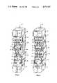
- FIG. 7is an exploded fragmentary perspective view illustrating dual spherical pivot members, a mounting block, adjusting rods, and fastener assembly of the apparatus in FIG. 1;
- FIG. 8is an exploded fragmentary perspective view illustrating a single spherical pivot member, mounting block, adjusting rod, and fastener assembly of the apparatus in FIG. 1;
- FIG. 9is a partially exploded fragmentary perspective view illustrating a single cylindrical pivot member, adjusting rod, and fastener assembly.
- FIG. 1A pair of assemblies 20 for moving a vertebra 22a to a desired relationship with other vertebrae 22b, 22c and for maintaining the desired relationship are illustrated in FIG. 1 connected with a human spinal column 24.
- Each of the assemblies 20includes adjusting rods 32 connected with mounting blocks 34, 36 which are attached to individual vertebrae 22 by fastener assemblies 42.
- the adjusting rods 32are connected with the spinal column 24 to move a vertebra 22a to a desired relationship with other vetebrae 22b, 22c and to maintain the vertebrae 22 in a desired relationship.
- two adjacent vertebrae 22b, 22c on each side of vertebra 22ahave the mounting blocks 34, 36 attached. This serves as an anchor from which to position vertebra 22a relative to.
- the vertebra 22ais moved relative to vetebrae 22b, 22c by rotating the adjusting rods 32 which interconnect the vertebra 22a with vertebrae 22b.
- a vertebra 22a(FIG. 2) is displaced relative to adjacent vertebrae 22b, 22c which are in a desired relationship in the spinal column 24.
- the vertebra 22ais illustrated displaced in the dorsal and sagittal directions. It will be obvious that the vertebra 22a could be displaced in just the dorsal direction or just the sagital direction.
- FIG. 2illustrates the spinous processes removed from the vertebrae 22a, 22b, and 22c which will have the assemblies attached.
- Two openings 46are formed in each of the vertebrae 22a, 22b, 22c for receiving force transmitting members.
- the openingsare formed so that they will be in approximate vertical alignment when the vertebrae 22a, 22b, 22c are in the desired relationship.
- Force transmitting members 52(FIG. 7) are then threaded into the openings 46 so that part of each force transmitting member extends from the vertebra 22.
- a first half 53a, 53b (FIGS. 7 and 8) of the mounting blocks 34, 36 for connecting pivot members 54 to the vertebrae 22is received on the force transmitting member 52 which extends from the vertebra.
- Pivot members 54are threaded onto the end portions of the adjusting rods 32.
- Each adjusting rod 32(FIG. 6) has an end portion with a righthand thread 55a and an end portion with a lefthand thread 55b.
- the pivot members 54(FIGS. 7 and 8) are received in chambers 58.
- a second half 62a, 62b of the mounting blocks 34, 36is received on the force transmitting member 52.
- a nut 64is sufficiently tightened onto the force transmitting member 52 to allow pivotal movement of the pivot members 54, but to restrict their rotational movement, relative the mounting blocks 34, 36.
- Each adjusting rod 32is rotated to move the vertebrae 22 to a desired relationship. The direction of rotation of the adjusting rod 32 depends upon whether the distance between the pivot members 54 threaded onto the rod is to increase or decrease.
- the nut 64is then further tightened to prevent any pivotal movement of the pivot joint 54 to maintain the vertebrae 22 in the desired relationship.
- FIG. 5An alternative application of the present invention is illustrated in FIG. 5.
- a single assembly 20is attached to the spinal column 24 to maintain the vertebrae 22 in a desired relationship.
- the structure of the single assembly 20 in FIG. 5is the same as that for either of the assemblies in FIG. 4.
- the fastener assembly 42(FIG. 4) connects a mounting block 34 or 36 with a vertebra 22 and presses the mounting block against the pivot members 54 (FIGS. 7 and 8).
- the fastener assembly 42includes a force transmitting member 52 having a first threaded portion 72 and a second threaded portion 74.
- the first threaded portion 72has a relatively large diameter helix for threading into an opening 46 formed in a vertebra 22.
- the first threaded portion 72has a substantially larger crest diameter than the inside diameter of the opening 46.
- the helixcuts into the cylindrical side surface of the opening to firmly attach the force transmitting member 52 to the vertebra 22.
- the force transmitting member 52is threaded into the vertebra 22 by placing a tool (not shown) on the hex head portion 78. The tool and force transmitting member 52 are then rotated until the desired depth of engagement with the vertebra 22 is obtained.
- the force transmitting member 52is made from a surgical grade stainless steel or titanium.
- the second threaded portion 74 of the force transmitting member 52has a standard external screw thread for engaging standard internal threads of the nut 64.
- the nut 64has a standard hexagonal external configuration for a suitable tool to engage for rotating the nut relative to the second threaded portion 74.
- the nut 64is rotated until it abuttingly engages a side of the second half 62a, 62b of a mounting block 34, 36. Initally, the nut 64 is rotated until the mounting block 34, 36 is pressed against the vertebra 22 with sufficient force to prevent the pivot member 54 from rotating but allowing pivotal movement.
- the adjusting rods 32are then rotated about their longitudinal axes to position the vertebrae 22 in a desired relationship.
- Force transmitting member 52has the same general construction disclosed in U.S. Pat. No. 4,611,581 for "Apparatus for Straightening Spinal Cclumns", by Arthur D. Steffee.
- the adjusting rod 32(FIGS. 3 and 4) interconnects, varies, and maintains the position of two vertebrae 22.
- the adjusting rod 32is made from a surgical grade stainless steel or titanium.
- each adjusting rod 32(FIG. 6) is installed to connect two vertebrae 22, it has a pair of pivot members 54 (FIG. 7) threaded onto end portions.
- One end portion 55ahas righthand threads and the other end portion 55b has lefthand threads. This forces the pivot members 54 to move in opposite directions along the rod 32 upon rotation of the rod about its longitudinal axis to effect relative movement between two vertebrae 22.
- the pivot members 54are threaded so that the axis of the threaded portion passes approximately through the center of the pivot member.
- the adjusting rod 32 having pivot members 54 threaded onto end portionsessentially creates a rigid link of adjustable length which can pivot at its two end portions.
- the linkcould have just one pivot member 54 threaded onto one end portion, while the other end portion has a pivot member rigidly connected or integrally formed thereon.
- the adjusting rod 32is rotated to change the distance between two vertebrae 22.
- the rodis rotated in a first direction, because of the righthand and lefthand threaded end portions, the distance between the pivot members 54 will increase. If the adjusting rod 32 is rotated in a second direction, the distance between the pivot members 54 will decrease.
- the interaction of the adjusting rod 32 and pivot members 54is similar to that of a turnbuckle.
- the adjusting rod 32is rotated by gripping the hex head portion 84 (FIG. 6) with a suitable tool (not shown) and rotating the tool.
- the hex head portion 84is integrally formed on the adjusting rod 32.
- Alternative means for rotating the adjusting rod 32can be provided.
- the adjusting rod 32could have an intermediate portion of the shaft itself formed with a hexagonal or square configuration and be about the same diameter as the threaded end portions 55a, 55b.
- the mounting blocks 34, 36(FIGS. 7 and 8) connect the pivot members 54 with the vertebrae 22 and prevent movement of the pivot members relative to the vertebrae.
- the mounting blocks 34, 36are designed to accept a pair of pivot members 54, as illustrated in FIG. 7, or a single pivot member, as illustrated in FIG. 8.
- the mounting blocks 34, 36are made from a material which is compatible with human tissue, generally a surgical grade stainless steel or titanium.
- FIG. 7illustrates the mounting block 36 used on intermediate vertebrae 22a, 22b (FIG. 4) for connecting a pair of spherical pivot members 54 with the vertebrae.
- the mounting block 36has a first half 53a and a second half 62a.
- Each half 53a, 62ahas a pair of surfaces which define generally spherical chambers 58 for receiving the pivot members 54.
- the size of the spherical chamber 58is such that it will prevent the pivot member 54 from pivotal movement relative to the mounting block 36 when the nut 64 is tightened against the mounting block. That is, the diameter of the spherical chamber 58 is equal to or slightly smaller than the diameter of the spherical pivot member 54. This permits the spherical chamber 58 to grip the member 54 for preventing pivotal movement when the nut is tightened to its final position against the mounting block.
- the mounting block 36has a first opening 88 through first side 92 and second side 94 of the mounting block 36 for receiving the force transmitting member 52 therethrough.
- the first side 92engages a vertebra 22.
- the second side 94engages the nut 64 for pressing the mounting block 36 to the vertebra 22 and around the pivot members 54.
- a pair of protrusions 98extend from the mounting block 36 around the opening 88 to add strength to the mounting block 36 and surface area for the vertebra 22 and nut 64 to engage.
- the size and configuration of the protrusions 98depends upon the overall dimensions of the mounting block 36 and opening 88. It will be obvious, for example, that the protrusions 98 can have a squared or rounded configuration.
- the mounting block 36has second and third openings 102, 104 respectively, which extend through third and fourth sides 106, 108 respectively, of the mounting block.
- the openings 102, 104are transverse to the first opening 88.
- the openings 102, 104have their longitudinal axes pass approximately through the center of spherical chambers 58 to allow the adjusting rods 32 to pass through for connection with the pivot members 54 and to pivot.
- the openings 102, 104are illustrated as countersunk but can be of a cylindrical configuration.
- the diameter of the openings 102, 104is smaller than that of the spherical chamber 58 and larger than the diameter of the adjusting rod 32. It will be obvious that it is not necessary for the openings 102, 104 to extend completely through the mounting block 36. For example, opening 102 could extend just through side 106, while opening 104 could extend just through side 108.
- FIG. 8illustrates a mounting block 34 used on the extreme ends of the assembly 20 (FIGS. 1, 4 and 5) for connecting a single spherical pivot member 54 with a vertebra 22.
- the design and function of the mounting block 34(FIG. 8) is similar to that described above for mounting block 36. That is, the mounting block 34 has a first half 53b and a second half 62b. A first opening 112 for receiving the force transmitting member 52 extends through both halves 53b, 62b.
- the mounting block 34has a single spherical chamber 58a for receiving the spherical pivot member 54.
- a second opening 114extends through the top 122 and bottom 124 of the mounting block 34 for allowing the adjusting rod 32 to pass through and pivot relative to the mounting block. The second opening 114 is transverse to the first opening 112.
- FIG. 9illustrates a cylindrical pivot joint 132 which allows pivotal movement only in the dorsal plane when the mounting block 128 is connected with a vertebra 22.
- the mounting block 128has a first half 53c and a second half 62c.
- the mounting block 128has a cylindrical chamber 134 for receiving the cylindrical pivot member 132.
- the mounting block 128has a first opening 136 extending through a first side 142 and a second side 144 of the mounting block 128.
- the cylindrical configuration of the pivot member 132prevents the pivot member from rotating relative to the mounting block when the adjusting rod 32 is rotated. Therefore, the force exerted by the nut 64 on the second side 144 of the mounting block 128 is not as critical as it would be for the spherical pivot member 54 arrangement to prevent rotation of the pivot member 54.
- a second opening 152is transverse to the first opening 136 and extends through a third side 154 and a fourth side 156 for allowing the adjusting rod 32 to engage the pivot member 132.
- the second opening 152is illustrated as being rectangular. It will be obvious that the second opening 152 can also be cylindrical as described above for mounting blocks 34 and 36 or tapered outwardly. It will also be obvious that a mounting block can be designed that will accept a pair of cylindrical pivot members 132 so that it can be used as an intermediate connector in the assembly 20 illustrated in FIG. 1.
- an improved apparatus and methodfor moving a vertebra 22a relative to other vertebrae 22b, 22c to a desired relationship and for maintaining the desired relationship.
- Mounting blocks 34, 36are attached to individual vertebrae 22 and interconnected by a plurality of adjusting rods 32.
- Pivot members 54are threaded onto threaded portions 55a, 55b of the adjusting rods 32 and received in the mounting blocks 34, 36. The relationship among vertebrae 22 is changed when the adjusting rods 32 are rotated thereby moving one vertebra relative to the other vertebrae.
Landscapes
- Health & Medical Sciences (AREA)
- Orthopedic Medicine & Surgery (AREA)
- Life Sciences & Earth Sciences (AREA)
- Neurology (AREA)
- Surgery (AREA)
- Heart & Thoracic Surgery (AREA)
- Engineering & Computer Science (AREA)
- Biomedical Technology (AREA)
- Nuclear Medicine, Radiotherapy & Molecular Imaging (AREA)
- Medical Informatics (AREA)
- Molecular Biology (AREA)
- Animal Behavior & Ethology (AREA)
- General Health & Medical Sciences (AREA)
- Public Health (AREA)
- Veterinary Medicine (AREA)
- Surgical Instruments (AREA)
- Prostheses (AREA)
Abstract
Description
The present invention relates to the correction of spinal deformities. Specifically, it relates to moving a vertebra to a desired relationship with other vertebrae and maintaining the desired relationship.
Devices for correcting spinal column deformities are known. U.S. Pat. No. 3,997,138 discloses a device which has a pair of flexible rods or cables to maintain adjacent vertebrae in a desired relationship. The rods or cables are secured to fasteners connected with the vertebrae.
Devices which include rigid plates are also known for securing vertebrae in a desired relationship. The plates are relatively heavy. Each plate has longitudinal slots formed therein which do not permit flexibility in locating fasteners laterally in the vertebrae.
Another known device for correcting spinal deformities is a ratchet system. The ratchet system includes a rod and ratchet blocks which engage the rod. The rod spans several vertebrae. The ratchet blocks have hooks. The hooks grab around pedicles on the vertebrae. The hooks are then drawn together by the rod to apply a desired correction to the spinal column. The ratchet system can only compress the spinal column.
In another device, the corrective forces are applied by two steel rods which are wired around the spine. The rods are not directly attached to all the vertebrae that the rods span. Maintaining a desired spatial relationship among the vertebrae spanned by the rods is difficult.
Another known spinal corrective device is disclosed in U.S. Pat. No. 4,041,939. The device includes fasteners which are threaded into the vertebrae. A cable is threaded through openings in the head of each fastener. Tension is applied to the cable to move the vertebrae to a desired relationship. The fasteners are crimped around the cable to maintain the desired relationship. This device can only compress the spinal column. Once the cable is crimped into place, no further adjustment is possible.
The present invention provides a series of adjustable length links to move a vertebra to a desired relationship with other vertebrae and to maintain the vertebrae in the desired relationship. The links can be subjected to either compressive or tensile forces.
Each link interconnects two adjacent vertebrae. Each link is adjustable independent of the other links. Thus, the spacing between a pair of vertebrae can be adjusted while the spacing between other vertebrae is maintained constant.
Each link includes a rod having pivot members threaded on each end portion of the rod. The pivot members are connected with adjacent vertebrae by mounting blocks fastened to individual vertebra. To vary the spacing between the adjacent vertebrae, the rod is rotated in order to change the spacing between two pivot members. Thus, since the pivot members are connected with adjacent vertebrae, the space between the adjacent vertebrae is also varied.
Further features of the present invention will become apparent to those skilled in the art to which the invention relates from a reading of the following specification made with reference to the accompanying drawings, in which:
FIG. 1 is a dorsal view of a portion of a spinal column with an apparatus constructed in accordance with the present invention installed to maintain a desired relationship of the vertebrae;
FIG. 2 is an enlarged schematic illustration of a spinal column having a displaced vertebra;
FIG. 3 is an enlarged schematic view, similar to FIG. 2, illustrating the apparatus installed on a spinal column before moving the displaced vertebra to a desired relationship;
FIG. 4 is an enlarged schematic view, similar to FIG. 3, illustrating the present invention installed on a spinal column after moving the displaced vertebra to the desired relationship;
FIG. 5 is an enlarged schematic view, similar to FIG. 4, illustrating another application of the present invention installed on a spinal column;
FIG. 6 is a perspective view illustrating an adjusting rod;
FIG. 7 is an exploded fragmentary perspective view illustrating dual spherical pivot members, a mounting block, adjusting rods, and fastener assembly of the apparatus in FIG. 1;
FIG. 8 is an exploded fragmentary perspective view illustrating a single spherical pivot member, mounting block, adjusting rod, and fastener assembly of the apparatus in FIG. 1; and
FIG. 9 is a partially exploded fragmentary perspective view illustrating a single cylindrical pivot member, adjusting rod, and fastener assembly.
A pair ofassemblies 20 for moving a vertebra 22a to a desired relationship withother vertebrae spinal column 24. Each of theassemblies 20 includes adjustingrods 32 connected withmounting blocks individual vertebrae 22 byfastener assemblies 42.
The adjustingrods 32 are connected with thespinal column 24 to move a vertebra 22a to a desired relationship withother vetebrae vertebrae 22 in a desired relationship. In order to maintain vertebra 22a in the desired relationship, as illustrated in FIG. 1, twoadjacent vertebrae mounting blocks vetebrae rods 32 which interconnect the vertebra 22a withvertebrae 22b.
Before installing theassemblies 20, a vertebra 22a (FIG. 2) is displaced relative toadjacent vertebrae spinal column 24. The vertebra 22a is illustrated displaced in the dorsal and sagittal directions. It will be obvious that the vertebra 22a could be displaced in just the dorsal direction or just the sagital direction.
To install theassemblies 20, the spinous processes 44 (FIG. 2) must be removed from thevertebrae 22 which will have theassemblies 20 attached. Thespinous processes 44 must be removed so that they will not interfere with the attachment and adjustment of theassemblies 20. FIG. 2 illustrates the spinous processes removed from thevertebrae
Twoopenings 46 are formed in each of thevertebrae vertebrae openings 46 so that part of each force transmitting member extends from thevertebra 22.
Afirst half 53a, 53b (FIGS. 7 and 8) of the mounting blocks 34, 36 for connectingpivot members 54 to thevertebrae 22 is received on theforce transmitting member 52 which extends from the vertebra.Pivot members 54 are threaded onto the end portions of the adjustingrods 32. Each adjusting rod 32 (FIG. 6) has an end portion with a righthand thread 55a and an end portion with alefthand thread 55b. The pivot members 54 (FIGS. 7 and 8) are received inchambers 58. Asecond half 62a, 62b of the mounting blocks 34, 36 is received on theforce transmitting member 52. Anut 64 is sufficiently tightened onto theforce transmitting member 52 to allow pivotal movement of thepivot members 54, but to restrict their rotational movement, relative the mounting blocks 34, 36. Each adjustingrod 32 is rotated to move thevertebrae 22 to a desired relationship. The direction of rotation of the adjustingrod 32 depends upon whether the distance between thepivot members 54 threaded onto the rod is to increase or decrease. Thenut 64 is then further tightened to prevent any pivotal movement of the pivot joint 54 to maintain thevertebrae 22 in the desired relationship.
An alternative application of the present invention is illustrated in FIG. 5. Asingle assembly 20 is attached to thespinal column 24 to maintain thevertebrae 22 in a desired relationship. The structure of thesingle assembly 20 in FIG. 5 is the same as that for either of the assemblies in FIG. 4.
The fastener assembly 42 (FIG. 4) connects a mountingblock vertebra 22 and presses the mounting block against the pivot members 54 (FIGS. 7 and 8). Thefastener assembly 42 includes aforce transmitting member 52 having a first threadedportion 72 and a second threadedportion 74. The first threadedportion 72 has a relatively large diameter helix for threading into anopening 46 formed in avertebra 22. The first threadedportion 72 has a substantially larger crest diameter than the inside diameter of theopening 46.
As the first threadedportion 72 is threaded into theopening 46, the helix cuts into the cylindrical side surface of the opening to firmly attach theforce transmitting member 52 to thevertebra 22. Theforce transmitting member 52 is threaded into thevertebra 22 by placing a tool (not shown) on thehex head portion 78. The tool andforce transmitting member 52 are then rotated until the desired depth of engagement with thevertebra 22 is obtained. Theforce transmitting member 52 is made from a surgical grade stainless steel or titanium.
The second threadedportion 74 of theforce transmitting member 52 has a standard external screw thread for engaging standard internal threads of thenut 64. Thenut 64 has a standard hexagonal external configuration for a suitable tool to engage for rotating the nut relative to the second threadedportion 74. Thenut 64 is rotated until it abuttingly engages a side of thesecond half 62a, 62b of a mountingblock nut 64 is rotated until the mountingblock vertebra 22 with sufficient force to prevent thepivot member 54 from rotating but allowing pivotal movement. The adjustingrods 32 are then rotated about their longitudinal axes to position thevertebrae 22 in a desired relationship. Thenut 64 is then rotated to a final position where thepivot member 54 is prevented from further pivotal movement, in order to maintain thevertebrae 22 in the desired relationship. The threadedportion 74 which extends beyond thenut 64 is then trimmed off adjacent to the nut.Force transmitting member 52 has the same general construction disclosed in U.S. Pat. No. 4,611,581 for "Apparatus for Straightening Spinal Cclumns", by Arthur D. Steffee.
The adjusting rod 32 (FIGS. 3 and 4) interconnects, varies, and maintains the position of twovertebrae 22. The adjustingrod 32 is made from a surgical grade stainless steel or titanium. Before each adjusting rod 32 (FIG. 6) is installed to connect twovertebrae 22, it has a pair of pivot members 54 (FIG. 7) threaded onto end portions. One end portion 55a has righthand threads and theother end portion 55b has lefthand threads. This forces thepivot members 54 to move in opposite directions along therod 32 upon rotation of the rod about its longitudinal axis to effect relative movement between twovertebrae 22. Thepivot members 54 are threaded so that the axis of the threaded portion passes approximately through the center of the pivot member.
The adjustingrod 32 havingpivot members 54 threaded onto end portions essentially creates a rigid link of adjustable length which can pivot at its two end portions. The link could have just onepivot member 54 threaded onto one end portion, while the other end portion has a pivot member rigidly connected or integrally formed thereon.
After thepivot members 54 are clamped by the mountingblock rod 32 is rotated to change the distance between twovertebrae 22. When the rod is rotated in a first direction, because of the righthand and lefthand threaded end portions, the distance between thepivot members 54 will increase. If the adjustingrod 32 is rotated in a second direction, the distance between thepivot members 54 will decrease. The interaction of the adjustingrod 32 andpivot members 54 is similar to that of a turnbuckle. Thus, since thepivot members 54 are connected with thevertebrae 22 by the mountingblocks rod 32 effects a change in the relative position of the two vertebrae.
The adjustingrod 32 is rotated by gripping the hex head portion 84 (FIG. 6) with a suitable tool (not shown) and rotating the tool. Thehex head portion 84 is integrally formed on the adjustingrod 32. Alternative means for rotating the adjustingrod 32 can be provided. For example, the adjustingrod 32 could have an intermediate portion of the shaft itself formed with a hexagonal or square configuration and be about the same diameter as the threadedend portions 55a, 55b.
The mounting blocks 34, 36 (FIGS. 7 and 8) connect thepivot members 54 with thevertebrae 22 and prevent movement of the pivot members relative to the vertebrae. The mounting blocks 34, 36 are designed to accept a pair ofpivot members 54, as illustrated in FIG. 7, or a single pivot member, as illustrated in FIG. 8. The mounting blocks 34, 36 are made from a material which is compatible with human tissue, generally a surgical grade stainless steel or titanium.
FIG. 7 illustrates the mountingblock 36 used onintermediate vertebrae 22a, 22b (FIG. 4) for connecting a pair ofspherical pivot members 54 with the vertebrae. The mountingblock 36 has a first half 53a and a second half 62a. Each half 53a, 62a has a pair of surfaces which define generallyspherical chambers 58 for receiving thepivot members 54. The size of thespherical chamber 58 is such that it will prevent thepivot member 54 from pivotal movement relative to the mountingblock 36 when thenut 64 is tightened against the mounting block. That is, the diameter of thespherical chamber 58 is equal to or slightly smaller than the diameter of thespherical pivot member 54. This permits thespherical chamber 58 to grip themember 54 for preventing pivotal movement when the nut is tightened to its final position against the mounting block.
The mountingblock 36 has afirst opening 88 throughfirst side 92 andsecond side 94 of the mountingblock 36 for receiving theforce transmitting member 52 therethrough. Thefirst side 92 engages avertebra 22. Thesecond side 94 engages thenut 64 for pressing the mountingblock 36 to thevertebra 22 and around thepivot members 54. A pair ofprotrusions 98 extend from the mountingblock 36 around theopening 88 to add strength to the mountingblock 36 and surface area for thevertebra 22 andnut 64 to engage. The size and configuration of theprotrusions 98 depends upon the overall dimensions of the mountingblock 36 andopening 88. It will be obvious, for example, that theprotrusions 98 can have a squared or rounded configuration.
The mountingblock 36 has second andthird openings fourth sides openings first opening 88. Theopenings spherical chambers 58 to allow the adjustingrods 32 to pass through for connection with thepivot members 54 and to pivot. Theopenings openings spherical chamber 58 and larger than the diameter of the adjustingrod 32. It will be obvious that it is not necessary for theopenings block 36. For example, opening 102 could extend just throughside 106, while opening 104 could extend just throughside 108.
FIG. 8 illustrates a mountingblock 34 used on the extreme ends of the assembly 20 (FIGS. 1, 4 and 5) for connecting a singlespherical pivot member 54 with avertebra 22. The design and function of the mounting block 34 (FIG. 8) is similar to that described above for mountingblock 36. That is, the mountingblock 34 has afirst half 53b and asecond half 62b. Afirst opening 112 for receiving theforce transmitting member 52 extends through bothhalves block 34 has a single spherical chamber 58a for receiving thespherical pivot member 54. Asecond opening 114 extends through the top 122 andbottom 124 of the mountingblock 34 for allowing the adjustingrod 32 to pass through and pivot relative to the mounting block. Thesecond opening 114 is transverse to thefirst opening 112.
FIG. 9 illustrates a cylindrical pivot joint 132 which allows pivotal movement only in the dorsal plane when the mountingblock 128 is connected with avertebra 22. The mountingblock 128 has afirst half 53c and asecond half 62c. The mountingblock 128 has acylindrical chamber 134 for receiving thecylindrical pivot member 132. The mountingblock 128 has afirst opening 136 extending through afirst side 142 and asecond side 144 of the mountingblock 128.
The cylindrical configuration of thepivot member 132 prevents the pivot member from rotating relative to the mounting block when the adjustingrod 32 is rotated. Therefore, the force exerted by thenut 64 on thesecond side 144 of the mountingblock 128 is not as critical as it would be for thespherical pivot member 54 arrangement to prevent rotation of thepivot member 54.
Asecond opening 152 is transverse to thefirst opening 136 and extends through athird side 154 and afourth side 156 for allowing the adjustingrod 32 to engage thepivot member 132. Thesecond opening 152 is illustrated as being rectangular. It will be obvious that thesecond opening 152 can also be cylindrical as described above for mountingblocks cylindrical pivot members 132 so that it can be used as an intermediate connector in theassembly 20 illustrated in FIG. 1.
In summary, an improved apparatus and method is provided for moving a vertebra 22a relative toother vertebrae individual vertebrae 22 and interconnected by a plurality of adjustingrods 32.Pivot members 54 are threaded onto threadedportions 55a, 55b of the adjustingrods 32 and received in the mounting blocks 34, 36. The relationship amongvertebrae 22 is changed when the adjustingrods 32 are rotated thereby moving one vertebra relative to the other vertebrae.
Claims (5)
1. A method for moving a first vertebra to a desired relationship with a second vertebra and for maintaining the first and second vertebrae in a desired relationship, said method comprising:
forming an opening in a first vertebra;
forming an opening in a second vertebra;
threading fasteners into the openings in the first and second vertebrae;
providing mounting blocks for attachment with the first and second vertebrae, each of the mounting blocks having first and second halves which cooperate to form a chamber for receiving a pivot member;
placing a first half of one mounting block onto the fastener in the first vertebra and a first half of another mounting block onto the fastener in the second vertebra;
providing a first pivot member having a righthand internally threaded portion and a second pivot member having a lefthand internally threaded portion;
providing a rod having a first end portion with a righthand thread and a second end portion with a lefthand thread;
threading the first pivot member onto the first end portion of the rod;
threading the second pivot member onto the second end portion of the rod;
placing the first pivot member into the portion of the chamber formed in the first half of the one mounting block on the first vertebra with the rod extending from the one mounting block towards the second vertebra;
placing the second pivot member into the chamber in the other mounting block on the second vertebra;
placing a second half of the one mounting block onto the fastener in the first vertebra;
placing a second half of the other mounting block onto the fastener in the second vertebra;
tightening nuts on respective fasteners with sufficient force to clamp the mounting blocks around the respective pivot members allowing pivotal movement of the pivot members relative to the mounting blocks and preventing rotational movement of the pivot members about the longitudinal central axis of the rod;
rotating the rod relative to the first and second pivot members to move the first vertebra relative to the second vertebra to a desired relationship; and
thereafter, tightening the nuts against the mounting blocks preventing pivotal and rotational movement of the pivot members relative to the mounting blocks thereby maintaining the desired relationship.
2. An apparatus comprising:
a first mounting block connectible with a first vertebra;
a second mounting block connectible with a second vertebra;
first fastening means for extending through an opening in said first mounting block to connect said first mounting block with a first vertebra;
second fastening means for extending through an opening in said second mounting block to connect said second mounting block with the second vertebra;
rod means rotatable about its longitudinal central axis extending between said first and second mounting blocks; and
means for pivotally connecting a first end portion of said rod means with said first mounting block and a second end portion of said rod means with said second mounting block and for supporting said rod means for rotation relative to said first and second mounting blocks, said means for pivotally connecting having a threaded portion cooperating with a threaded end portion of said rod means to effect relative movement of the first and second vertebrae upon rotation of said rod means;
each of said first and second mounting blocks including a pair of halves, each of said pair of halves having a surface defining a portion of a chamber for receiving said means for pivotally connected when said halves are pressed together by tightening said respective fastening means against said mounting block, said mounting block also having a surface defining another opening for receiving said rod means therein and extending through said mounting block to said chamber in a direction transversely to said opening for said fastening means.
3. An apparatus as set forth in claim 2 wherein said means for pivotally connecting includes pivot members of a generally spherical configuration, each of said pivot members having an internally threaded portion passing approximately through the center of said pivot member for receiving said externally threaded end portion of said rod means, said chamber in each of said first and second mounting blocks being of a generally spherical configuration for receiving a respective one of said pivot members.
4. An apparatus as set forth in claim 2 wherein said means for pivotally connecting includes pivot members of a generally cylindrical configuration, each of said pivot members having an internally threaded portion transversely intersecting the longitudinal axis of said pivot member for receiving said externally threaded end portion of said rod means, said chamber in each of said first and second mounting blocks being of a generally cylindrical configuration for receiving a respective one of said pivot members.
5. An apparatus comprising:
a first mounting block connectible with a first vertebra;
a second mounting block connectible with a second vertebra;
first fastening means for connecting said first mounting block with the first vertebra;
second fastening means for connecting said second mounting block with the second vertebra;
rod means rotatable about its longitudinal central axis extending between said first and second mounting blocks; and
means for pivotally connecting a first end portion of said rod means with said first mounting block and for pivotally connecting a second end portion of said rod means with said second mounting block and for supporting said rod means for rotation relative to said first and second mounting blocks, said means for pivotally connecting having a threaded portion cooperating with a threaded end portion of said rod means to effect relative movement of the first and second vertebrae upon rotation of said rod means;
each of said first and second mounting blocks including a pair of halves, each of said pair of halves having a surface defining a portion of a chamber for receiving said means for pivotally connecting when said halves are pressed together, each of said pair of halves also having a surface defining a first opening in each of said first and second mounting blocks and which first opening extends through said mounting block to said chamber for receiving said rod means, each of said first and second mounting blocks including a surface defining a second opening therethrough and extending in a direction transverse to said first opening, said first and second fastening means extending through the respective second opening in each respective mounting block to press said halves of said mounting blocks together.
Priority Applications (1)
| Application Number | Priority Date | Filing Date | Title |
|---|---|---|---|
| US06/825,251US4771767A (en) | 1986-02-03 | 1986-02-03 | Apparatus and method for maintaining vertebrae in a desired relationship |
Applications Claiming Priority (1)
| Application Number | Priority Date | Filing Date | Title |
|---|---|---|---|
| US06/825,251US4771767A (en) | 1986-02-03 | 1986-02-03 | Apparatus and method for maintaining vertebrae in a desired relationship |
Publications (1)
| Publication Number | Publication Date |
|---|---|
| US4771767Atrue US4771767A (en) | 1988-09-20 |
Family
ID=25243515
Family Applications (1)
| Application Number | Title | Priority Date | Filing Date |
|---|---|---|---|
| US06/825,251Expired - Fee RelatedUS4771767A (en) | 1986-02-03 | 1986-02-03 | Apparatus and method for maintaining vertebrae in a desired relationship |
Country Status (1)
| Country | Link |
|---|---|
| US (1) | US4771767A (en) |
Cited By (108)
| Publication number | Priority date | Publication date | Assignee | Title |
|---|---|---|---|---|
| DE3841008A1 (en)* | 1988-12-06 | 1990-06-07 | Heinrich Ulrich | Implant for correction of the spine |
| EP0425783A1 (en)* | 1989-10-30 | 1991-05-08 | Synthes AG, Chur | Pedicle screw clamp |
| US5034011A (en)* | 1990-08-09 | 1991-07-23 | Advanced Spine Fixation Systems Incorporated | Segmental instrumentation of the posterior spine |
| US5057109A (en)* | 1989-10-16 | 1991-10-15 | Sven Olerud | Fixing instruments for spinal surgery |
| US5133717A (en)* | 1990-02-08 | 1992-07-28 | Societe De Fabrication De Material Orthopedique Sofamor | Sacral support saddle for a spinal osteosynthesis device |
| US5176679A (en)* | 1991-09-23 | 1993-01-05 | Lin Chih I | Vertebral locking and retrieving system |
| US5207678A (en)* | 1989-07-20 | 1993-05-04 | Prufer | Pedicle screw and receiver member therefore |
| US5209752A (en)* | 1991-12-04 | 1993-05-11 | Danek Medical, Inc. | Lateral offset connector for spinal implant system |
| US5222954A (en)* | 1991-06-21 | 1993-06-29 | Artifex, Ltd. | Spinal implant system and method for installing the implant |
| EP0556548A1 (en)* | 1992-02-19 | 1993-08-25 | Acromed Corporation | Apparatus for maintaining spinal elements in a desired spatial relationship |
| US5254118A (en)* | 1991-12-04 | 1993-10-19 | Srdjian Mirkovic | Three dimensional spine fixation system |
| EP0570929A1 (en)* | 1992-05-18 | 1993-11-24 | Pina Vertriebs Ag | Implant for the spine |
| EP0537598A3 (en)* | 1991-10-18 | 1993-12-22 | Pina Vertriebs Ag | Compressive margical implant |
| US5282862A (en)* | 1991-12-03 | 1994-02-01 | Artifex Ltd. | Spinal implant system and a method for installing the implant onto a vertebral column |
| US5334203A (en)* | 1992-09-30 | 1994-08-02 | Amei Technologies Inc. | Spinal fixation system and methods |
| US5344421A (en)* | 1993-07-16 | 1994-09-06 | Amei Technologies Inc. | Apparatus and method for adjusting a bone plate |
| WO1995010238A1 (en)* | 1993-10-08 | 1995-04-20 | Chaim Rogozinski | Spinal treatment apparatus and method including multi-directional attachment member |
| WO1995010239A1 (en)* | 1993-10-08 | 1995-04-20 | Chaim Rogozinski | Spinal treatment and long bone fixation apparatus and method |
| US5437669A (en)* | 1993-08-12 | 1995-08-01 | Amei Technologies Inc. | Spinal fixation systems with bifurcated connectors |
| US5466237A (en)* | 1993-11-19 | 1995-11-14 | Cross Medical Products, Inc. | Variable locking stabilizer anchor seat and screw |
| US5474551A (en)* | 1994-11-18 | 1995-12-12 | Smith & Nephew Richards, Inc. | Universal coupler for spinal fixation |
| US5474555A (en)* | 1990-04-26 | 1995-12-12 | Cross Medical Products | Spinal implant system |
| US5496321A (en)* | 1993-11-19 | 1996-03-05 | Cross Medical Products, Inc. | Rod anchor seat having a sliding interlocking rod connector |
| WO1996027340A1 (en)* | 1995-03-06 | 1996-09-12 | Stryker France S.A. | Spinal instruments, particularly for a rod |
| US5569248A (en)* | 1992-03-17 | 1996-10-29 | Danek Medical, Inc. | Apparatus for subcutaneous suprafascial pedicular internal fixation |
| US5571102A (en)* | 1992-09-15 | 1996-11-05 | Cavagna; Remi | System for spinal osteosynthesis |
| US5645544A (en)* | 1995-09-13 | 1997-07-08 | Danek Medical, Inc. | Variable angle extension rod |
| US5984925A (en)* | 1997-07-30 | 1999-11-16 | Cross Medical Products, Inc. | Longitudinally adjustable bone plates and method for use thereof |
| US6099528A (en)* | 1997-05-29 | 2000-08-08 | Sofamor S.N.C. | Vertebral rod for spinal osteosynthesis instrumentation and osteosynthesis instrumentation, including said rod |
| US6432108B1 (en) | 2000-01-24 | 2002-08-13 | Depuy Orthopaedics, Inc. | Transverse connector |
| US20020138077A1 (en)* | 2001-03-26 | 2002-09-26 | Ferree Bret A. | Spinal alignment apparatus and methods |
| US6458131B1 (en) | 2000-08-07 | 2002-10-01 | Salut, Ltd. | Apparatus and method for reducing spinal deformity |
| US6478798B1 (en) | 2001-05-17 | 2002-11-12 | Robert S. Howland | Spinal fixation apparatus and methods for use |
| US20030045878A1 (en)* | 1999-12-03 | 2003-03-06 | Dominique Petit | Connecting assembly for spinal osteosynthesis |
| US20030065329A1 (en)* | 2001-10-03 | 2003-04-03 | Vaughan Paul A. | Vertebral stabilization assembly and method |
| US20040087949A1 (en)* | 2002-10-31 | 2004-05-06 | Bono Frank S. | Snap-in washers and assemblies thereof |
| US6736817B2 (en) | 1999-12-17 | 2004-05-18 | Thomas N. Troxell | Transconnector for coupling spinal rods |
| US20040111088A1 (en)* | 2002-12-06 | 2004-06-10 | Picetti George D. | Multi-rod bone attachment member |
| US6770075B2 (en) | 2001-05-17 | 2004-08-03 | Robert S. Howland | Spinal fixation apparatus with enhanced axial support and methods for use |
| US20040215190A1 (en)* | 2003-04-25 | 2004-10-28 | Nguyen Thanh V. | System and method for minimally invasive posterior fixation |
| US20040220570A1 (en)* | 1998-05-19 | 2004-11-04 | Synthes (Usa) | Osteosynthetic implant with an embedded hinge joint |
| US20050177161A1 (en)* | 2004-02-10 | 2005-08-11 | Baynham Bret O. | Static anterior cervical plate |
| US20050240181A1 (en)* | 2004-04-23 | 2005-10-27 | Boomer Mark C | Spinal implant connectors |
| US20050240185A1 (en)* | 2004-04-23 | 2005-10-27 | Depuy Spine Sarl | Spinal fixation plates and plate extensions |
| US20050277932A1 (en)* | 2004-06-15 | 2005-12-15 | Sdgi Holdings, Inc. | Spinal rod system |
| US7066938B2 (en) | 2002-09-09 | 2006-06-27 | Depuy Spine, Inc. | Snap-on spinal rod connector |
| US20060189999A1 (en)* | 2005-02-24 | 2006-08-24 | Paul Zwirkoski | Linked slideable and interlockable rotatable components |
| US20060247627A1 (en)* | 2005-04-29 | 2006-11-02 | Sdgi Holdings, Inc. | Spinal construct system |
| US7141051B2 (en) | 2003-02-05 | 2006-11-28 | Pioneer Laboratories, Inc. | Low profile spinal fixation system |
| US20070005063A1 (en)* | 2005-06-20 | 2007-01-04 | Sdgi Holdings, Inc. | Multi-level multi-functional spinal stabilization systems and methods |
| US20070043357A1 (en)* | 2005-07-29 | 2007-02-22 | X-Spine Systems, Inc. | Capless multiaxial screw and spinal fixation assembly and method |
| US20070225708A1 (en)* | 2005-12-23 | 2007-09-27 | Lutz Biedermann | Dynamic stabilization device for bones or vertebrae |
| US20070233068A1 (en)* | 2006-02-22 | 2007-10-04 | Sdgi Holdings, Inc. | Intervertebral prosthetic assembly for spinal stabilization and method of implanting same |
| US20070233070A1 (en)* | 2006-03-01 | 2007-10-04 | Sdgi Holdings, Inc. | Low profile spinal rod connector system |
| US20070270838A1 (en)* | 2006-05-08 | 2007-11-22 | Sdgi Holdings, Inc. | Dynamic spinal stabilization device with dampener |
| US20070270837A1 (en)* | 2006-05-08 | 2007-11-22 | Sdgi Holdings, Inc. | Load bearing flexible spinal connecting element |
| US20070270836A1 (en)* | 2006-05-08 | 2007-11-22 | Sdgi Holdings, Inc. | Dynamic spinal stabilization members and methods |
| US20070270805A1 (en)* | 2006-04-07 | 2007-11-22 | Sdgi Holdings, Inc. | Spinal rod connector system and method for a bone anchor |
| US7314467B2 (en) | 2002-04-24 | 2008-01-01 | Medical Device Advisory Development Group, Llc. | Multi selective axis spinal fixation system |
| US20080086126A1 (en)* | 2006-08-31 | 2008-04-10 | Warsaw Orthopedic, Inc. | Spinal Rod Extenders and Methods of Use |
| US20080177318A1 (en)* | 2007-01-18 | 2008-07-24 | Warsaw Orthopedic, Inc. | Vertebral Stabilizer |
| US20080195100A1 (en)* | 2007-02-08 | 2008-08-14 | Warsaw Orthopedic, Inc. | Adjustable coupling systems for spinal stabilization members |
| US20080269805A1 (en)* | 2007-04-25 | 2008-10-30 | Warsaw Orthopedic, Inc. | Methods for correcting spinal deformities |
| US20080312655A1 (en)* | 2007-06-14 | 2008-12-18 | X-Spine Systems, Inc. | Polyaxial screw system and method having a hinged receiver |
| JP2009513306A (en)* | 2005-10-31 | 2009-04-02 | ストライカー・スピン | System and method for dynamic vertebra stabilization |
| US20090105763A1 (en)* | 2007-10-17 | 2009-04-23 | X-Spine Systems, Inc. | Cross connector apparatus for spinal fixation rods |
| US20090163961A1 (en)* | 2007-12-19 | 2009-06-25 | X-Spine Systems, Inc. | Offset multiaxial or polyaxial screw, system and assembly |
| US7588588B2 (en) | 2003-10-21 | 2009-09-15 | Innovative Spinal Technologies | System and method for stabilizing of internal structures |
| US7604655B2 (en) | 2004-10-25 | 2009-10-20 | X-Spine Systems, Inc. | Bone fixation system and method for using the same |
| US7618442B2 (en) | 2003-10-21 | 2009-11-17 | Theken Spine, Llc | Implant assembly and method for use in an internal structure stabilization system |
| US7645294B2 (en) | 2004-03-31 | 2010-01-12 | Depuy Spine, Inc. | Head-to-head connector spinal fixation system |
| US20100010544A1 (en)* | 2005-02-22 | 2010-01-14 | Stryker Spine | Apparatus and method for dynamic vertebral stabilization |
| US7662172B2 (en) | 2004-10-25 | 2010-02-16 | X-Spine Systems, Inc. | Pedicle screw systems and methods of assembling/installing the same |
| US20100049252A1 (en)* | 2008-08-21 | 2010-02-25 | Southern Spine, Llc | Transverse Connector Device for Extending an Existing Spinal Fixation System |
| US7686835B2 (en) | 2005-10-04 | 2010-03-30 | X-Spine Systems, Inc. | Pedicle screw system with provisional locking aspects |
| US7717939B2 (en) | 2004-03-31 | 2010-05-18 | Depuy Spine, Inc. | Rod attachment for head to head cross connector |
| US7717938B2 (en) | 2004-08-27 | 2010-05-18 | Depuy Spine, Inc. | Dual rod cross connectors and inserter tools |
| US7833251B1 (en) | 2004-01-06 | 2010-11-16 | Nuvasive, Inc. | System and method for performing spinal fixation |
| US7879074B2 (en) | 2005-09-27 | 2011-02-01 | Depuy Spine, Inc. | Posterior dynamic stabilization systems and methods |
| US7967826B2 (en) | 2003-10-21 | 2011-06-28 | Theken Spine, Llc | Connector transfer tool for internal structure stabilization systems |
| US20110245883A1 (en)* | 2008-11-05 | 2011-10-06 | Vagn Erik Dall | Bone Fixation Device |
| US20110301646A1 (en)* | 2010-01-05 | 2011-12-08 | The Johns Hopkins University | Compression-distraction spinal fixation system |
| US8097025B2 (en) | 2005-10-25 | 2012-01-17 | X-Spine Systems, Inc. | Pedicle screw system configured to receive a straight or curved rod |
| US8172885B2 (en) | 2003-02-05 | 2012-05-08 | Pioneer Surgical Technology, Inc. | Bone plate system |
| US20120283781A1 (en)* | 2009-11-25 | 2012-11-08 | Uri Arnin | Spinal rod having a post-operative adjustable dimension |
| US8357181B2 (en) | 2005-10-27 | 2013-01-22 | Warsaw Orthopedic, Inc. | Intervertebral prosthetic device for spinal stabilization and method of implanting same |
| US8361126B2 (en) | 2007-07-03 | 2013-01-29 | Pioneer Surgical Technology, Inc. | Bone plate system |
| US8361117B2 (en) | 2006-11-08 | 2013-01-29 | Depuy Spine, Inc. | Spinal cross connectors |
| US8623019B2 (en) | 2007-07-03 | 2014-01-07 | Pioneer Surgical Technology, Inc. | Bone plate system |
| US8821546B2 (en) | 2007-11-06 | 2014-09-02 | Stanus Investments, Inc. | Vertebral screw arrangement with locking pin |
| US20140305982A1 (en)* | 2013-10-22 | 2014-10-16 | Department Of The Navy, U.S. Marine Corps | Central osteoarticular relief and performance structured load distribution system device and modular scalable vest system |
| US8968367B2 (en) | 2010-01-05 | 2015-03-03 | The Johns Hopkins University | Compression-distraction spinal fixation system and kit |
| US9060813B1 (en) | 2008-02-29 | 2015-06-23 | Nuvasive, Inc. | Surgical fixation system and related methods |
| US20150173804A1 (en)* | 2012-07-24 | 2015-06-25 | CARBOFIX IN ORTHOPEDICS LLC a corporation | Spine system and kit |
| GB2524883A (en)* | 2014-02-28 | 2015-10-07 | Fitzbionics Ltd | Connector for spinal implant system |
| US20150305779A1 (en)* | 2012-08-21 | 2015-10-29 | Pierre M. Montavon | Spring and device for stabilizing human or animal bone |
| US9198696B1 (en) | 2010-05-27 | 2015-12-01 | Nuvasive, Inc. | Cross-connector and related methods |
| US9247964B1 (en) | 2011-03-01 | 2016-02-02 | Nuasive, Inc. | Spinal Cross-connector |
| US9387013B1 (en) | 2011-03-01 | 2016-07-12 | Nuvasive, Inc. | Posterior cervical fixation system |
| US9439679B2 (en) | 2008-11-05 | 2016-09-13 | Dalmatic Lystrup A/S | Bone fixation system |
| US9504307B1 (en)* | 2014-09-29 | 2016-11-29 | The United States Of America As Represented By The Secretary Of The Air Force | Articulating resistive conformable spine |
| US9717531B2 (en) | 2013-10-18 | 2017-08-01 | Warsaw Orthopedic, Inc. | Spinal correction method and system |
| US11123214B2 (en)* | 2017-09-11 | 2021-09-21 | Peter Wilson | Back-brace assistive device |
| US11224462B2 (en)* | 2018-12-05 | 2022-01-18 | Biedermann Technologies Gmbh & Co. Kg | Coupling device, in particular for use in orthopedic surgery |
| US11331125B1 (en) | 2021-10-07 | 2022-05-17 | Ortho Inventions, Llc | Low profile rod-to-rod coupler |
| US20230018799A1 (en)* | 2021-07-16 | 2023-01-19 | Joon Hyeok Choi | Upper garment with customized spine support device |
| EP4285848A1 (en)* | 2022-05-16 | 2023-12-06 | Warsaw Orthopedic, Inc. | Spinal implant system |
| US11877779B2 (en) | 2020-03-26 | 2024-01-23 | Xtant Medical Holdings, Inc. | Bone plate system |
Citations (9)
| Publication number | Priority date | Publication date | Assignee | Title |
|---|---|---|---|---|
| US3242922A (en)* | 1963-06-25 | 1966-03-29 | Charles B Thomas | Internal spinal fixation means |
| US3426364A (en)* | 1966-08-25 | 1969-02-11 | Colorado State Univ Research F | Prosthetic appliance for replacing one or more natural vertebrae |
| DE2821678A1 (en)* | 1978-05-12 | 1979-11-22 | Sulzer Ag | IMPLANT THAT CAN BE INSERTED BETWEEN NEIGHBORING Vertebrae |
| SU839515A1 (en)* | 1979-09-12 | 1981-06-23 | Костно-Туберкулезный Санаторий"Урал" Свердловского Областногоотдела Здравоохранения | B.i.byzov's and ja.b.byzov's device for treating spinal curvature |
| DE3132520A1 (en)* | 1980-11-18 | 1982-06-16 | Gebrüder Sulzer AG, 8401 Winterthur | Spondylodesis stabiliser |
| US4401112A (en)* | 1980-09-15 | 1983-08-30 | Rezaian Seyed M | Spinal fixator |
| US4553273A (en)* | 1983-11-23 | 1985-11-19 | Henry Ford Hospital | Vertebral body prosthesis and spine stabilizing method |
| US4611581A (en)* | 1983-12-16 | 1986-09-16 | Acromed Corporation | Apparatus for straightening spinal columns |
| US4611580A (en)* | 1983-11-23 | 1986-09-16 | Henry Ford Hospital | Intervertebral body stabilization |
- 1986
- 1986-02-03USUS06/825,251patent/US4771767A/ennot_activeExpired - Fee Related
Patent Citations (9)
| Publication number | Priority date | Publication date | Assignee | Title |
|---|---|---|---|---|
| US3242922A (en)* | 1963-06-25 | 1966-03-29 | Charles B Thomas | Internal spinal fixation means |
| US3426364A (en)* | 1966-08-25 | 1969-02-11 | Colorado State Univ Research F | Prosthetic appliance for replacing one or more natural vertebrae |
| DE2821678A1 (en)* | 1978-05-12 | 1979-11-22 | Sulzer Ag | IMPLANT THAT CAN BE INSERTED BETWEEN NEIGHBORING Vertebrae |
| SU839515A1 (en)* | 1979-09-12 | 1981-06-23 | Костно-Туберкулезный Санаторий"Урал" Свердловского Областногоотдела Здравоохранения | B.i.byzov's and ja.b.byzov's device for treating spinal curvature |
| US4401112A (en)* | 1980-09-15 | 1983-08-30 | Rezaian Seyed M | Spinal fixator |
| DE3132520A1 (en)* | 1980-11-18 | 1982-06-16 | Gebrüder Sulzer AG, 8401 Winterthur | Spondylodesis stabiliser |
| US4553273A (en)* | 1983-11-23 | 1985-11-19 | Henry Ford Hospital | Vertebral body prosthesis and spine stabilizing method |
| US4611580A (en)* | 1983-11-23 | 1986-09-16 | Henry Ford Hospital | Intervertebral body stabilization |
| US4611581A (en)* | 1983-12-16 | 1986-09-16 | Acromed Corporation | Apparatus for straightening spinal columns |
Cited By (220)
| Publication number | Priority date | Publication date | Assignee | Title |
|---|---|---|---|---|
| DE3841008A1 (en)* | 1988-12-06 | 1990-06-07 | Heinrich Ulrich | Implant for correction of the spine |
| US5207678A (en)* | 1989-07-20 | 1993-05-04 | Prufer | Pedicle screw and receiver member therefore |
| US5057109A (en)* | 1989-10-16 | 1991-10-15 | Sven Olerud | Fixing instruments for spinal surgery |
| EP0425783A1 (en)* | 1989-10-30 | 1991-05-08 | Synthes AG, Chur | Pedicle screw clamp |
| US5133717A (en)* | 1990-02-08 | 1992-07-28 | Societe De Fabrication De Material Orthopedique Sofamor | Sacral support saddle for a spinal osteosynthesis device |
| US5624442A (en)* | 1990-04-26 | 1997-04-29 | Cross Medical Products, Inc. | Transverse link for use with a spinal implant system |
| US5474555A (en)* | 1990-04-26 | 1995-12-12 | Cross Medical Products | Spinal implant system |
| US5034011A (en)* | 1990-08-09 | 1991-07-23 | Advanced Spine Fixation Systems Incorporated | Segmental instrumentation of the posterior spine |
| US5222954A (en)* | 1991-06-21 | 1993-06-29 | Artifex, Ltd. | Spinal implant system and method for installing the implant |
| US5176679A (en)* | 1991-09-23 | 1993-01-05 | Lin Chih I | Vertebral locking and retrieving system |
| EP0534053A3 (en)* | 1991-09-23 | 1993-07-21 | Chih-I Lin | Vertebral locking and retrieving system |
| EP0537598A3 (en)* | 1991-10-18 | 1993-12-22 | Pina Vertriebs Ag | Compressive margical implant |
| US5282862A (en)* | 1991-12-03 | 1994-02-01 | Artifex Ltd. | Spinal implant system and a method for installing the implant onto a vertebral column |
| US5209752A (en)* | 1991-12-04 | 1993-05-11 | Danek Medical, Inc. | Lateral offset connector for spinal implant system |
| US5254118A (en)* | 1991-12-04 | 1993-10-19 | Srdjian Mirkovic | Three dimensional spine fixation system |
| EP0556548A1 (en)* | 1992-02-19 | 1993-08-25 | Acromed Corporation | Apparatus for maintaining spinal elements in a desired spatial relationship |
| US6793656B1 (en) | 1992-03-17 | 2004-09-21 | Sdgi Holdings, Inc. | Systems and methods for fixation of adjacent vertebrae |
| US5569248A (en)* | 1992-03-17 | 1996-10-29 | Danek Medical, Inc. | Apparatus for subcutaneous suprafascial pedicular internal fixation |
| US5728097A (en)* | 1992-03-17 | 1998-03-17 | Sdgi Holding, Inc. | Method for subcutaneous suprafascial internal fixation |
| US20050038434A1 (en)* | 1992-03-17 | 2005-02-17 | Mathews Hallett H. | Systems and methods for fixation of adjacent vertebrae |
| US5380324A (en)* | 1992-05-18 | 1995-01-10 | Pina Vertriebs Ag | Implantable device for straightening and fixing vertebrae |
| EP0570929A1 (en)* | 1992-05-18 | 1993-11-24 | Pina Vertriebs Ag | Implant for the spine |
| US5571102A (en)* | 1992-09-15 | 1996-11-05 | Cavagna; Remi | System for spinal osteosynthesis |
| US5334203A (en)* | 1992-09-30 | 1994-08-02 | Amei Technologies Inc. | Spinal fixation system and methods |
| US5344421A (en)* | 1993-07-16 | 1994-09-06 | Amei Technologies Inc. | Apparatus and method for adjusting a bone plate |
| US5437669A (en)* | 1993-08-12 | 1995-08-01 | Amei Technologies Inc. | Spinal fixation systems with bifurcated connectors |
| WO1995010239A1 (en)* | 1993-10-08 | 1995-04-20 | Chaim Rogozinski | Spinal treatment and long bone fixation apparatus and method |
| WO1995010238A1 (en)* | 1993-10-08 | 1995-04-20 | Chaim Rogozinski | Spinal treatment apparatus and method including multi-directional attachment member |
| US5607425A (en)* | 1993-10-08 | 1997-03-04 | Rogozinski; Chaim | Apparatus, method and system for the treatment of spinal conditions |
| US5496321A (en)* | 1993-11-19 | 1996-03-05 | Cross Medical Products, Inc. | Rod anchor seat having a sliding interlocking rod connector |
| US5466237A (en)* | 1993-11-19 | 1995-11-14 | Cross Medical Products, Inc. | Variable locking stabilizer anchor seat and screw |
| USRE39035E1 (en)* | 1994-11-18 | 2006-03-21 | Howmedica Osteonics Corp. | Universal coupler for spinal fixation |
| US5474551A (en)* | 1994-11-18 | 1995-12-12 | Smith & Nephew Richards, Inc. | Universal coupler for spinal fixation |
| WO1996027340A1 (en)* | 1995-03-06 | 1996-09-12 | Stryker France S.A. | Spinal instruments, particularly for a rod |
| AU697705B2 (en)* | 1995-03-06 | 1998-10-15 | Stryker France | Spinal instruments, particularly for rods |
| US5938663A (en)* | 1995-03-06 | 1999-08-17 | Stryker France, S.A. | Spinal instruments, particularly for a rod |
| FR2731344A1 (en)* | 1995-03-06 | 1996-09-13 | Dimso Sa | SPINAL INSTRUMENTATION ESPECIALLY FOR A ROD |
| JP3418939B2 (en) | 1995-03-06 | 2003-06-23 | ストライカー フランス ソシエテ アノニム | Spinal mounts, especially for rods |
| US5645544A (en)* | 1995-09-13 | 1997-07-08 | Danek Medical, Inc. | Variable angle extension rod |
| US6099528A (en)* | 1997-05-29 | 2000-08-08 | Sofamor S.N.C. | Vertebral rod for spinal osteosynthesis instrumentation and osteosynthesis instrumentation, including said rod |
| US6102912A (en)* | 1997-05-29 | 2000-08-15 | Sofamor S.N.C. | Vertebral rod of constant section for spinal osteosynthesis instrumentations |
| US6364881B1 (en)* | 1997-07-30 | 2002-04-02 | Interpore Cross International | Longitudinally adjustable bone plates and method for use thereof |
| US5984925A (en)* | 1997-07-30 | 1999-11-16 | Cross Medical Products, Inc. | Longitudinally adjustable bone plates and method for use thereof |
| US7887569B2 (en)* | 1998-05-19 | 2011-02-15 | Synthes Usa, Llc | Osteosynthetic implant with an embedded hinge joint |
| US20040220570A1 (en)* | 1998-05-19 | 2004-11-04 | Synthes (Usa) | Osteosynthetic implant with an embedded hinge joint |
| US20030045878A1 (en)* | 1999-12-03 | 2003-03-06 | Dominique Petit | Connecting assembly for spinal osteosynthesis |
| US6736817B2 (en) | 1999-12-17 | 2004-05-18 | Thomas N. Troxell | Transconnector for coupling spinal rods |
| US6761721B2 (en) | 2000-01-24 | 2004-07-13 | Depuy Acromed, Inc. | Transverse connector |
| US6432108B1 (en) | 2000-01-24 | 2002-08-13 | Depuy Orthopaedics, Inc. | Transverse connector |
| US6458131B1 (en) | 2000-08-07 | 2002-10-01 | Salut, Ltd. | Apparatus and method for reducing spinal deformity |
| US20040260287A1 (en)* | 2001-03-26 | 2004-12-23 | Nuvasive, Inc. | Spinal alignment system and related methods |
| US20020138077A1 (en)* | 2001-03-26 | 2002-09-26 | Ferree Bret A. | Spinal alignment apparatus and methods |
| US20080071275A1 (en)* | 2001-03-26 | 2008-03-20 | Nu Vasive, Inc. | Spinal alignment system and related methods |
| US6802844B2 (en) | 2001-03-26 | 2004-10-12 | Nuvasive, Inc | Spinal alignment apparatus and methods |
| US6478798B1 (en) | 2001-05-17 | 2002-11-12 | Robert S. Howland | Spinal fixation apparatus and methods for use |
| US6770075B2 (en) | 2001-05-17 | 2004-08-03 | Robert S. Howland | Spinal fixation apparatus with enhanced axial support and methods for use |
| US7713291B2 (en) | 2001-10-03 | 2010-05-11 | Vaughan Medical Technologies, Inc. | Vertebral stabilization assembly and method |
| US20060149243A1 (en)* | 2001-10-03 | 2006-07-06 | Vaughan Paul A | Vertebral stabilization assembly and method |
| US20030065329A1 (en)* | 2001-10-03 | 2003-04-03 | Vaughan Paul A. | Vertebral stabilization assembly and method |
| US7087056B2 (en) | 2001-10-03 | 2006-08-08 | Vaughan Medical Technologies, Inc. | Vertebral stabilization assembly and method |
| US7645280B2 (en) | 2001-10-03 | 2010-01-12 | Vaughan Medical Technologies, Inc. | Vertebral stabilization assembly and method |
| US7713290B2 (en) | 2001-10-03 | 2010-05-11 | Vaughan Medical Technologies, Inc. | Vertebral stabilization assembly and method |
| US20040254578A1 (en)* | 2001-10-03 | 2004-12-16 | Vaughan Paul A. | Vertebral stabilization assembly and method |
| US20050240183A1 (en)* | 2001-10-03 | 2005-10-27 | Vaughan Medical Technologies, Inc. | Vertebral stabilization assembly and method |
| US20050267473A1 (en)* | 2001-10-03 | 2005-12-01 | Vaughan Paul A | Vertebral stabilization assembly and method with rigid and semi-rigid members |
| US20040193161A1 (en)* | 2001-10-03 | 2004-09-30 | Vaughan Paul A. | Vertebral stabilization assembly and method |
| US7314467B2 (en) | 2002-04-24 | 2008-01-01 | Medical Device Advisory Development Group, Llc. | Multi selective axis spinal fixation system |
| US7066938B2 (en) | 2002-09-09 | 2006-06-27 | Depuy Spine, Inc. | Snap-on spinal rod connector |
| US7306602B2 (en) | 2002-10-31 | 2007-12-11 | Depuy Actomed, Inc. | Snap-in washers and assemblies thereof |
| US20040087949A1 (en)* | 2002-10-31 | 2004-05-06 | Bono Frank S. | Snap-in washers and assemblies thereof |
| US20040111088A1 (en)* | 2002-12-06 | 2004-06-10 | Picetti George D. | Multi-rod bone attachment member |
| US8172885B2 (en) | 2003-02-05 | 2012-05-08 | Pioneer Surgical Technology, Inc. | Bone plate system |
| US7141051B2 (en) | 2003-02-05 | 2006-11-28 | Pioneer Laboratories, Inc. | Low profile spinal fixation system |
| US20050038432A1 (en)* | 2003-04-25 | 2005-02-17 | Shaolian Samuel M. | Articulating spinal fixation rod and system |
| US7083621B2 (en)* | 2003-04-25 | 2006-08-01 | Sdgi Holdings, Inc. | Articulating spinal fixation rod and system |
| US20070016194A1 (en)* | 2003-04-25 | 2007-01-18 | Shaolian Samuel M | Articulating spinal fixation rod and system |
| US20090082809A1 (en)* | 2003-04-25 | 2009-03-26 | Warsaw Orthopedic, Inc. | System and Method for Minimally Invasive Posterior Fixation |
| US7473267B2 (en) | 2003-04-25 | 2009-01-06 | Warsaw Orthopedic, Inc. | System and method for minimally invasive posterior fixation |
| US8211153B2 (en) | 2003-04-25 | 2012-07-03 | Warsaw Orthopedic, Inc. | Articulating spinal fixation rod and system |
| US20040215190A1 (en)* | 2003-04-25 | 2004-10-28 | Nguyen Thanh V. | System and method for minimally invasive posterior fixation |
| US8317838B2 (en) | 2003-04-25 | 2012-11-27 | Warsaw Orthopedic | System and method for minimally invasive posterior fixation |
| US7618442B2 (en) | 2003-10-21 | 2009-11-17 | Theken Spine, Llc | Implant assembly and method for use in an internal structure stabilization system |
| US7588588B2 (en) | 2003-10-21 | 2009-09-15 | Innovative Spinal Technologies | System and method for stabilizing of internal structures |
| US7967826B2 (en) | 2003-10-21 | 2011-06-28 | Theken Spine, Llc | Connector transfer tool for internal structure stabilization systems |
| US7905907B2 (en) | 2003-10-21 | 2011-03-15 | Theken Spine, Llc | Internal structure stabilization system for spanning three or more structures |
| US7833251B1 (en) | 2004-01-06 | 2010-11-16 | Nuvasive, Inc. | System and method for performing spinal fixation |
| US20050177161A1 (en)* | 2004-02-10 | 2005-08-11 | Baynham Bret O. | Static anterior cervical plate |
| US7468069B2 (en)* | 2004-02-10 | 2008-12-23 | Atlas Spine, Inc. | Static anterior cervical plate |
| US9629663B2 (en) | 2004-03-31 | 2017-04-25 | DePuy Synthes Products, Inc. | Rod attachment for head to head cross connector |
| US8920469B2 (en) | 2004-03-31 | 2014-12-30 | Depuy Synthes Products Llc | Rod attachment for head to head cross connector |
| US8591550B2 (en) | 2004-03-31 | 2013-11-26 | Depuy Spine, Inc. | Rod attachement for head to head connector |
| US8192471B2 (en) | 2004-03-31 | 2012-06-05 | Depuy Spine, Inc. | Rod attachment for head to head cross connector |
| US7645294B2 (en) | 2004-03-31 | 2010-01-12 | Depuy Spine, Inc. | Head-to-head connector spinal fixation system |
| US9486247B2 (en) | 2004-03-31 | 2016-11-08 | DePuy Synthes Products, Inc. | Rod attachment for head to head cross connector |
| US7717939B2 (en) | 2004-03-31 | 2010-05-18 | Depuy Spine, Inc. | Rod attachment for head to head cross connector |
| US8920470B2 (en) | 2004-03-31 | 2014-12-30 | Depuy Synthes Products Llc | Rod attachment for head to head cross connector |
| US8556937B2 (en) | 2004-03-31 | 2013-10-15 | DePuy Synthes Products, LLC | Rod attachment for head to head cross connector |
| US9387014B2 (en) | 2004-03-31 | 2016-07-12 | DePuy Synthes Products, Inc. | Systems and methods for decompressing a spinal canal |
| US7967845B2 (en) | 2004-03-31 | 2011-06-28 | Depuy Spine, Inc. | Head-to-head connector spinal fixation system |
| US20100010541A1 (en)* | 2004-04-23 | 2010-01-14 | Depuy Spine Sarl | Spinal fixation plates and plate extensions |
| US20050240185A1 (en)* | 2004-04-23 | 2005-10-27 | Depuy Spine Sarl | Spinal fixation plates and plate extensions |
| US20050240181A1 (en)* | 2004-04-23 | 2005-10-27 | Boomer Mark C | Spinal implant connectors |
| US7572282B2 (en) | 2004-04-23 | 2009-08-11 | Depuy Spine Sarl | Spinal fixation plates and plate extensions |
| US8728080B2 (en) | 2004-04-23 | 2014-05-20 | Depuy Spine Sarl | Spinal fixation plates and plate extensions |
| US20050277926A1 (en)* | 2004-06-15 | 2005-12-15 | Farris Robert A | Spinal rod system |
| US20050277932A1 (en)* | 2004-06-15 | 2005-12-15 | Sdgi Holdings, Inc. | Spinal rod system |
| US7175622B2 (en)* | 2004-06-15 | 2007-02-13 | Warsaw Orthopedic, Inc. | Spinal rod system |
| US7744634B2 (en) | 2004-06-15 | 2010-06-29 | Warsaw Orthopedic, Inc. | Spinal rod system |
| JP2008502423A (en)* | 2004-06-15 | 2008-01-31 | ウォーソー・オーソペディック・インコーポレーテッド | Spinal rod system |
| US8961572B2 (en) | 2004-08-27 | 2015-02-24 | Depuy Synthes Products Llc | Dual rod cross connectors and inserter tools |
| US7717938B2 (en) | 2004-08-27 | 2010-05-18 | Depuy Spine, Inc. | Dual rod cross connectors and inserter tools |
| US8372119B2 (en) | 2004-08-27 | 2013-02-12 | Depuy Spine, Inc. | Dual rod cross connectors and inserter tools |
| US8012185B2 (en) | 2004-10-25 | 2011-09-06 | X-Spine Systems, Inc. | Pedicle screw systems and methods of assembling/installing the same |
| US20100063553A1 (en)* | 2004-10-25 | 2010-03-11 | X-Spine Systems, Inc. | Bone fixation method |
| US8142481B2 (en) | 2004-10-25 | 2012-03-27 | X-Spine Systems, Inc. | Pedicle screw systems and methods of assembling/installing the same |
| US20100179603A1 (en)* | 2004-10-25 | 2010-07-15 | X-Spine Systems, Inc. | Pedicle screw systems and methods of assembling/installing the same |
| US8147522B2 (en) | 2004-10-25 | 2012-04-03 | X-Spine Systems, Inc. | Bone fixation method |
| US7662172B2 (en) | 2004-10-25 | 2010-02-16 | X-Spine Systems, Inc. | Pedicle screw systems and methods of assembling/installing the same |
| US8092504B2 (en) | 2004-10-25 | 2012-01-10 | X-Spine Systems, Inc. | Pedicle screw systems and methods of assembling/installing the same |
| US7604655B2 (en) | 2004-10-25 | 2009-10-20 | X-Spine Systems, Inc. | Bone fixation system and method for using the same |
| US20100010544A1 (en)* | 2005-02-22 | 2010-01-14 | Stryker Spine | Apparatus and method for dynamic vertebral stabilization |
| US20100042153A1 (en)* | 2005-02-22 | 2010-02-18 | Fallin T Wade | Apparatus And Method For Dynamic Vertebral Stabilization |
| US8226687B2 (en) | 2005-02-22 | 2012-07-24 | Stryker Spine | Apparatus and method for dynamic vertebral stabilization |
| US8974499B2 (en) | 2005-02-22 | 2015-03-10 | Stryker Spine | Apparatus and method for dynamic vertebral stabilization |
| US9486244B2 (en) | 2005-02-22 | 2016-11-08 | Stryker European Holdings I, Llc | Apparatus and method for dynamic vertebral stabilization |
| US9949762B2 (en) | 2005-02-22 | 2018-04-24 | Stryker European Holdings I, Llc | Apparatus and method for dynamic vertebral stabilization |
| US8034109B2 (en) | 2005-02-24 | 2011-10-11 | Morphogeny, Llc | Linked slideable and interlockable rotatable components |
| US20060189999A1 (en)* | 2005-02-24 | 2006-08-24 | Paul Zwirkoski | Linked slideable and interlockable rotatable components |
| US7993371B2 (en) | 2005-04-29 | 2011-08-09 | Warsaw Orthopedic, Inc. | Spinal construct system |
| US20060247627A1 (en)* | 2005-04-29 | 2006-11-02 | Sdgi Holdings, Inc. | Spinal construct system |
| US20070005063A1 (en)* | 2005-06-20 | 2007-01-04 | Sdgi Holdings, Inc. | Multi-level multi-functional spinal stabilization systems and methods |
| US7828825B2 (en) | 2005-06-20 | 2010-11-09 | Warsaw Orthopedic, Inc. | Multi-level multi-functional spinal stabilization systems and methods |
| US20070043357A1 (en)* | 2005-07-29 | 2007-02-22 | X-Spine Systems, Inc. | Capless multiaxial screw and spinal fixation assembly and method |
| US8382806B2 (en) | 2005-07-29 | 2013-02-26 | X-Spine Systems, Inc. | Capless multiaxial screw and spinal fixation assembly and method |
| US7717943B2 (en) | 2005-07-29 | 2010-05-18 | X-Spine Systems, Inc. | Capless multiaxial screw and spinal fixation assembly and method |
| US20070123867A1 (en)* | 2005-07-29 | 2007-05-31 | X-Spine Systems, Inc. | Capless multiaxial screw and spinal fixation assembly and method |
| US8066745B2 (en) | 2005-07-29 | 2011-11-29 | X-Spine Systems, Inc. | Capless multiaxial screw and spinal fixation assembly and method |
| US20100204738A1 (en)* | 2005-07-29 | 2010-08-12 | X-Spine Systems, Inc. | Capless multiaxial screw and spinal fixation assembly and method |
| US7879074B2 (en) | 2005-09-27 | 2011-02-01 | Depuy Spine, Inc. | Posterior dynamic stabilization systems and methods |
| US20100152788A1 (en)* | 2005-10-04 | 2010-06-17 | X-Spine Systems, Inc. | Pedicle screw system with provisional locking aspects |
| US7686835B2 (en) | 2005-10-04 | 2010-03-30 | X-Spine Systems, Inc. | Pedicle screw system with provisional locking aspects |
| US8016866B2 (en) | 2005-10-04 | 2011-09-13 | X-Spine Systems, Inc. | Pedicle screw system with provisional locking aspects |
| US8097025B2 (en) | 2005-10-25 | 2012-01-17 | X-Spine Systems, Inc. | Pedicle screw system configured to receive a straight or curved rod |
| US8357181B2 (en) | 2005-10-27 | 2013-01-22 | Warsaw Orthopedic, Inc. | Intervertebral prosthetic device for spinal stabilization and method of implanting same |
| JP2009513306A (en)* | 2005-10-31 | 2009-04-02 | ストライカー・スピン | System and method for dynamic vertebra stabilization |
| US8979902B2 (en) | 2005-12-23 | 2015-03-17 | Biedermann Technologies Gmbh & Co. Kg | Dynamic stabilization device for bones or vertebrae |
| US20070225708A1 (en)* | 2005-12-23 | 2007-09-27 | Lutz Biedermann | Dynamic stabilization device for bones or vertebrae |
| US8192468B2 (en)* | 2005-12-23 | 2012-06-05 | Biedermann Technologies Gmbh & Co. Kg | Dynamic stabilization device for bones or vertebrae |
| US20070233068A1 (en)* | 2006-02-22 | 2007-10-04 | Sdgi Holdings, Inc. | Intervertebral prosthetic assembly for spinal stabilization and method of implanting same |
| US7699874B2 (en) | 2006-03-01 | 2010-04-20 | Warsaw Orthopedic, Inc. | Low profile spinal rod connector system |
| US20070233070A1 (en)* | 2006-03-01 | 2007-10-04 | Sdgi Holdings, Inc. | Low profile spinal rod connector system |
| US20070270805A1 (en)* | 2006-04-07 | 2007-11-22 | Sdgi Holdings, Inc. | Spinal rod connector system and method for a bone anchor |
| US7867255B2 (en) | 2006-04-07 | 2011-01-11 | Warsaw Orthopedic, Inc. | Spinal rod connector system and method for a bone anchor |
| US7785350B2 (en) | 2006-05-08 | 2010-08-31 | Warsaw Orthopedic, Inc. | Load bearing flexible spinal connecting element |
| US20070270837A1 (en)* | 2006-05-08 | 2007-11-22 | Sdgi Holdings, Inc. | Load bearing flexible spinal connecting element |
| US20100298883A1 (en)* | 2006-05-08 | 2010-11-25 | Warsaw Orthopedic, Inc. | Load Bearing Flexible Spinal Connecting Element |
| US8231657B2 (en) | 2006-05-08 | 2012-07-31 | Warsaw Orthopedic | Load bearing flexible spinal connecting element |
| US20070270838A1 (en)* | 2006-05-08 | 2007-11-22 | Sdgi Holdings, Inc. | Dynamic spinal stabilization device with dampener |
| US20070270836A1 (en)* | 2006-05-08 | 2007-11-22 | Sdgi Holdings, Inc. | Dynamic spinal stabilization members and methods |
| US8012179B2 (en) | 2006-05-08 | 2011-09-06 | Warsaw Orthopedic, Inc. | Dynamic spinal stabilization members and methods |
| US20080086126A1 (en)* | 2006-08-31 | 2008-04-10 | Warsaw Orthopedic, Inc. | Spinal Rod Extenders and Methods of Use |
| US7922746B2 (en)* | 2006-08-31 | 2011-04-12 | Warsaw Orthopedic, Inc. | Spinal rod extenders and methods of use |
| US8361117B2 (en) | 2006-11-08 | 2013-01-29 | Depuy Spine, Inc. | Spinal cross connectors |
| US8870921B2 (en) | 2006-11-08 | 2014-10-28 | DePuy Synthes Products, LLC | Spinal cross connectors |
| US20080177318A1 (en)* | 2007-01-18 | 2008-07-24 | Warsaw Orthopedic, Inc. | Vertebral Stabilizer |
| US7931676B2 (en) | 2007-01-18 | 2011-04-26 | Warsaw Orthopedic, Inc. | Vertebral stabilizer |
| US8372121B2 (en) | 2007-02-08 | 2013-02-12 | Warsaw Orthopedic, Inc. | Adjustable coupling systems for spinal stabilization members |
| US20080195100A1 (en)* | 2007-02-08 | 2008-08-14 | Warsaw Orthopedic, Inc. | Adjustable coupling systems for spinal stabilization members |
| US20080269805A1 (en)* | 2007-04-25 | 2008-10-30 | Warsaw Orthopedic, Inc. | Methods for correcting spinal deformities |
| US20080312655A1 (en)* | 2007-06-14 | 2008-12-18 | X-Spine Systems, Inc. | Polyaxial screw system and method having a hinged receiver |
| US8623019B2 (en) | 2007-07-03 | 2014-01-07 | Pioneer Surgical Technology, Inc. | Bone plate system |
| US9655665B2 (en) | 2007-07-03 | 2017-05-23 | Pioneer Surgical Technology, Inc. | Bone plate systems |
| US10898247B2 (en) | 2007-07-03 | 2021-01-26 | Pioneer Surgical Technology, Inc. | Bone plate system |
| US10226291B2 (en) | 2007-07-03 | 2019-03-12 | Pioneer Surgical Technology, Inc. | Bone plate system |
| US9381046B2 (en) | 2007-07-03 | 2016-07-05 | Pioneer Surgical Technology, Inc. | Bone plate system |
| US8361126B2 (en) | 2007-07-03 | 2013-01-29 | Pioneer Surgical Technology, Inc. | Bone plate system |
| US20090105763A1 (en)* | 2007-10-17 | 2009-04-23 | X-Spine Systems, Inc. | Cross connector apparatus for spinal fixation rods |
| US7922747B2 (en) | 2007-10-17 | 2011-04-12 | X-Spine Systems, Inc. | Cross connector apparatus for spinal fixation rods |
| US8821546B2 (en) | 2007-11-06 | 2014-09-02 | Stanus Investments, Inc. | Vertebral screw arrangement with locking pin |
| US20090163961A1 (en)* | 2007-12-19 | 2009-06-25 | X-Spine Systems, Inc. | Offset multiaxial or polyaxial screw, system and assembly |
| US8480714B2 (en) | 2007-12-19 | 2013-07-09 | X-Spine Systems, Inc. | Offset multiaxial or polyaxial screw, system and assembly |
| US8029539B2 (en) | 2007-12-19 | 2011-10-04 | X-Spine Systems, Inc. | Offset multiaxial or polyaxial screw, system and assembly |
| US9198691B2 (en) | 2007-12-19 | 2015-12-01 | X-Spine Systems, Inc. | Offset multiaxial or polyaxial screw, system and assembly |
| US9060813B1 (en) | 2008-02-29 | 2015-06-23 | Nuvasive, Inc. | Surgical fixation system and related methods |
| US20100049252A1 (en)* | 2008-08-21 | 2010-02-25 | Southern Spine, Llc | Transverse Connector Device for Extending an Existing Spinal Fixation System |
| US20110245883A1 (en)* | 2008-11-05 | 2011-10-06 | Vagn Erik Dall | Bone Fixation Device |
| US8657857B2 (en)* | 2008-11-05 | 2014-02-25 | Dalmatic Lystrup A/S | Bone fixation device |
| US9439679B2 (en) | 2008-11-05 | 2016-09-13 | Dalmatic Lystrup A/S | Bone fixation system |
| US9078703B2 (en)* | 2009-11-25 | 2015-07-14 | Spine21 Ltd. | Spinal rod having a post-operative adjustable dimension |
| US20120283781A1 (en)* | 2009-11-25 | 2012-11-08 | Uri Arnin | Spinal rod having a post-operative adjustable dimension |
| US20110301646A1 (en)* | 2010-01-05 | 2011-12-08 | The Johns Hopkins University | Compression-distraction spinal fixation system |
| US8864800B2 (en)* | 2010-01-05 | 2014-10-21 | The Johns Hopkins University | Compression-distraction spinal fixation system |
| US8968367B2 (en) | 2010-01-05 | 2015-03-03 | The Johns Hopkins University | Compression-distraction spinal fixation system and kit |
| US9198696B1 (en) | 2010-05-27 | 2015-12-01 | Nuvasive, Inc. | Cross-connector and related methods |
| US9770269B1 (en) | 2011-03-01 | 2017-09-26 | Nuvasive, Inc. | Spinal Cross-connector |
| US9247964B1 (en) | 2011-03-01 | 2016-02-02 | Nuasive, Inc. | Spinal Cross-connector |
| US11123110B2 (en) | 2011-03-01 | 2021-09-21 | Nuvasive, Inc. | Posterior cervical fixation system |
| US10779865B2 (en) | 2011-03-01 | 2020-09-22 | Nuvasive, Inc. | Spinal cross connector |
| US11478282B2 (en) | 2011-03-01 | 2022-10-25 | Nuvasive, Inc. | Spinal cross connector |
| US9387013B1 (en) | 2011-03-01 | 2016-07-12 | Nuvasive, Inc. | Posterior cervical fixation system |
| US9956009B1 (en) | 2011-03-01 | 2018-05-01 | Nuvasive, Inc. | Posterior cervical fixation system |
| US10368918B2 (en) | 2011-03-01 | 2019-08-06 | Nuvasive, Inc. | Posterior cervical fixation system |
| US10136925B2 (en) | 2011-03-01 | 2018-11-27 | Nuvasive, Inc. | Spinal cross-connector |
| US20150173804A1 (en)* | 2012-07-24 | 2015-06-25 | CARBOFIX IN ORTHOPEDICS LLC a corporation | Spine system and kit |
| US20150305779A1 (en)* | 2012-08-21 | 2015-10-29 | Pierre M. Montavon | Spring and device for stabilizing human or animal bone |
| US9717531B2 (en) | 2013-10-18 | 2017-08-01 | Warsaw Orthopedic, Inc. | Spinal correction method and system |
| US20140305982A1 (en)* | 2013-10-22 | 2014-10-16 | Department Of The Navy, U.S. Marine Corps | Central osteoarticular relief and performance structured load distribution system device and modular scalable vest system |
| US10383377B1 (en) | 2013-10-22 | 2019-08-20 | U.S. Government As Represented By The Secretary Of The Army | Articulating load distribution system |
| US9700122B2 (en)* | 2013-10-22 | 2017-07-11 | Dept. Of The Navy, A U.S. Government Agency, By The U.S. Marine Corps | Central osteoarticular relief and performance structured load distribution system device and modular scalable vest system |
| GB2524883B (en)* | 2014-02-28 | 2016-07-20 | Fitzbionics Ltd | Connector for spinal implant system |
| GB2524883A (en)* | 2014-02-28 | 2015-10-07 | Fitzbionics Ltd | Connector for spinal implant system |
| US10058357B2 (en) | 2014-02-28 | 2018-08-28 | Fitzbionics Limited | Connector for spinal implant system |
| US9504307B1 (en)* | 2014-09-29 | 2016-11-29 | The United States Of America As Represented By The Secretary Of The Air Force | Articulating resistive conformable spine |
| US11123214B2 (en)* | 2017-09-11 | 2021-09-21 | Peter Wilson | Back-brace assistive device |
| US11224462B2 (en)* | 2018-12-05 | 2022-01-18 | Biedermann Technologies Gmbh & Co. Kg | Coupling device, in particular for use in orthopedic surgery |
| US11877779B2 (en) | 2020-03-26 | 2024-01-23 | Xtant Medical Holdings, Inc. | Bone plate system |
| US20230018799A1 (en)* | 2021-07-16 | 2023-01-19 | Joon Hyeok Choi | Upper garment with customized spine support device |
| US11596188B2 (en)* | 2021-07-16 | 2023-03-07 | Joon Hyeok Choi | Upper garment with customized spine support device |
| US11331125B1 (en) | 2021-10-07 | 2022-05-17 | Ortho Inventions, Llc | Low profile rod-to-rod coupler |
| EP4285848A1 (en)* | 2022-05-16 | 2023-12-06 | Warsaw Orthopedic, Inc. | Spinal implant system |
Similar Documents
| Publication | Publication Date | Title |
|---|---|---|
| US4771767A (en) | Apparatus and method for maintaining vertebrae in a desired relationship | |
| EP0220736B1 (en) | Apparatus for maintaining vertebrae in a desired relationship | |
| US4719905A (en) | Apparatus and method for maintaining vertebrae in a desired relationship | |
| US5084049A (en) | Transverse connector for spinal column corrective devices | |
| KR960004979B1 (en) | Vertebrae retention device | |
| US5360429A (en) | Device for straightening, fixing, compressing, and elongating cervical vertebrae | |
| US5403316A (en) | Triangular construct for spinal fixation | |
| US5344422A (en) | Pedicular screw clamp | |
| US6641583B2 (en) | Apparatus for retaining bone portions in a desired spatial relationship | |
| US5468241A (en) | Support device for the human vertebral column | |
| US5741255A (en) | Spinal column retaining apparatus | |
| US5728127A (en) | Apparatus for maintaining vertebrae of a spinal column in a desired spatial relationship | |
| US7175622B2 (en) | Spinal rod system | |
| US6183473B1 (en) | Variable angle connection assembly for a spinal implant system | |
| KR100493994B1 (en) | Multi-axial bone screw assembly | |
| US5667506A (en) | Spinal rod transverse connector for supporting vertebral fixation elements | |
| EP0425783B1 (en) | Pedicle screw clamp | |
| US5545163A (en) | Spinal fixation system | |
| JP3776456B2 (en) | Bone fixation device to fix the upper part | |
| US6146382A (en) | Occipito-cervical stabilization system and method | |
| EP0506420B1 (en) | Bone fixation apparatus | |
| US7722645B2 (en) | Pedicle screw spinal fixation device | |
| US20060064092A1 (en) | Selective axis serrated rod low profile spinal fixation system | |
| US20020143327A1 (en) | Transverse connector for use in spinal corrective surgery | |
| EP0468264A1 (en) | Spinal column retaining method and apparatus |
Legal Events
| Date | Code | Title | Description |
|---|---|---|---|
| AS | Assignment | Owner name:ACROMED CORPORATION, CLEVELAND, CUYAHOGA, OHIO, A Free format text:ASSIGNMENT OF ASSIGNORS INTEREST.;ASSIGNOR:STEFFEE, ARTHUR D.;REEL/FRAME:004513/0203 Effective date:19860131 | |
| FEPP | Fee payment procedure | Free format text:PAYOR NUMBER ASSIGNED (ORIGINAL EVENT CODE: ASPN); ENTITY STATUS OF PATENT OWNER: SMALL ENTITY | |
| FPAY | Fee payment | Year of fee payment:4 | |
| AS | Assignment | Owner name:SOCIETY NATIONAL BANK, OHIO Free format text:SECURITY INTEREST;ASSIGNOR:ACROMED CORPORATION, AN OH CORPORATION;REEL/FRAME:006002/0106 Effective date:19910702 | |
| REMI | Maintenance fee reminder mailed | ||
| LAPS | Lapse for failure to pay maintenance fees | ||
| FP | Lapsed due to failure to pay maintenance fee | Effective date:19960925 | |
| STCH | Information on status: patent discontinuation | Free format text:PATENT EXPIRED DUE TO NONPAYMENT OF MAINTENANCE FEES UNDER 37 CFR 1.362 |